Introduction
In order to maintain the stability of overdentures, protective copings need to be placed over the coronal part of the teeth. This component plays a vital role in supporting the alveolar ridge and providing adequate axially distributed loads maintaing the level of the alveolar ridge. This improves denture stability. [
1,
2] Various types of protective copings have been presented to the public. [
1,
2,
3,
4,
5,
6,
7,
8] Although they can be beneficial for the use of overdentures, they can be very costly and can be hard to implement due to the intricate technique involved. Furthermore, the different types of interfaces between the denture base and copings might alter the strain and stress pattern around the abutment teeth.[
4,
5,
6]
This study investigated a particular, simpler shape of the copings on the residual tooth structure in the lower jaw. These copings functioned as both bone preservers in the surrounding alveolar regions and as retainers for the overdenture. Because they are occlusally designed to have at least indications of the occlusal relief of the tooth that will support the lower jaw overdenture, and because they are circumferentially milled along the gingival surface, these copings are unique from all others previously described in the dental literature. This research was established on the basic assumption and preliminary findings that patients in clinical practice were satisfied with these forms of specific-purpose copings, claiming that they contributed towards improved retention of their overdenture. [
1] It is still unclear if the pressure on the copings significantly redistributes occlusal forces in accordance with morphologically shaped surfaces that correspond to the occlusal topography and whether it significantly contributes to the stabilization of the prosthesis on the supporting tissues.[
1,
5,
6,
7]
The aim of this study was to examine the effect of differential stress distributions on the occlusal surfaces of the control and experimental copings on artificial casts of partially edentulous jaws.
Materials and Methods
The experiment was accomplished at the Faculty of Mechanical Engineering, University of Belgrade, Serbia.
This study included two master casts of a lower jaw, with bilateral terminal edentulous seats. Their topography was the same, including missing lower molars, the left lower second premolar, and the right canine and incisors representing the situation of a partially-edentulous lower jaw according to the B3 (and C2) classification of Eichner (i.e. Kennedy class 1).
The control cast was designed with conventional oval forms of copings which are most often used in clinical practice to preserve the remaining dental substance in the crown and for receiving the base surface of the overdenture.
The experimental cast was almost the same as the control cast, with the exception of the surfaces simulating three specific milled copings covering the remaining tooth substance. Specific copings were shaped so that in the occlusal third they had elements of morphological characteristics of teeth; they discretely indicated rounded prominences which are partly similar to the tips of the cusps of natural teeth. In the gingival third the copings were milled so that the circumference of each coping achieved a step shape (i.e. chamfer, or shoulder) for the retention and stabilization of the base of the correspondent denture surface.
Master casts were fabricated in a 3D printer using specific polymethyl resin material (Formlabs Photopolymer Resin, Formlabs Inc., Somerville, MA, USA). Resin material was presumed to be linear elastic, homogenous, and isotropic. The corresponding elastic properties, including the Young’s modulus and Poisson ratio, were determined according to the values obtained from the previously published literature. [
9]
The surfaces of the casts were sprayed with a thin coat of white layer paint, followed by a thin layer of high contrast black paint placed on top of the white layer to allow for the correct performance of the digital image correlation (DIC) method. Points of the spray occupied distances that were changed under loading and were registered by cameras.
Precise and controlled loading was measured using a gnathodynamometer (SiemensAG, Erlangen, Germany) with horizontal extension. Axial occlusal loads were applied centrally and vertically to the distal abutment tooth (the first lower premolar), intermediate abutment tooth (canine), and the mesial abutment tooth (the second lower incisor). The direction of loadings to the second experimental cast was the same. The loading stages were at 400, 800, and 1000 N.
Measurements of the strain and displacement were provided by the Digital Image Correlation Method (GOM-Optical Measuring Techniques, Braunschweig, Germany). This system consists of two digital cameras and the associated software ARAMIS (Version 6.2.0; GOM-Optical Measuring Techniques). ARAMIS software, based on the principle of an objective fine-ground procedure, registered 3D changes in the shape and distribution of the strain on the surface of statically- or dynamically-loaded objects. Moreover, ARAMIS also determined the shape of the photographed object with high accuracy, its dimensions, its field of 3D movements, the vector of the distorted field, and features of the biomaterial.
Mobile cameras at specific time intervals photographed the distance between reference points before loading, in the calibration phase, and during the action force. Before measuring the strains of the control and the experimental copings, a calibration procedure was performed. To measure 3D strains, two cameras were positioned manually and adjusted in accordance with the measuring volume of the calibration object. Strains within the selected area could be measured over a range from 0.01% up to several hundred percent, and strain accuracy was as high as 0.01%. [
10,
11]
Small and large objects, from 1- 2.000 mm, could be measured with the same sensor.
The software processing of the data measured enabled recording of the results and 3D presentation.
Statistical analysis
Descriptive statistics were used to present the findings regarding the deformation and displacements of the tooth copings obtained in this experiment. The MEANS procedure from the statistical package SAS (SAS Institute 2010) was used for analysis. ‘Wilcoxon Lambda’ tests based on the simple linear rank statistics were used for the analyses of numerical values of distortions and displacements of copings. The mean value was shown as a measure of central tendency. Nonparametric statistical methods based on the scores of a response variable (percent of deformation and displacement) were used to determine the differences between the mean vales in the experimental and control copings.
Results
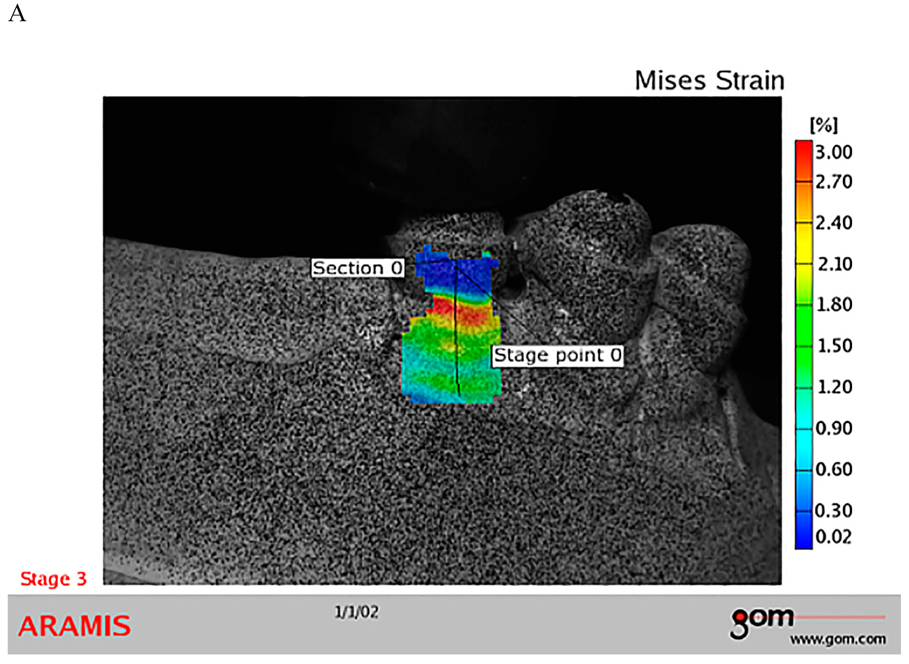
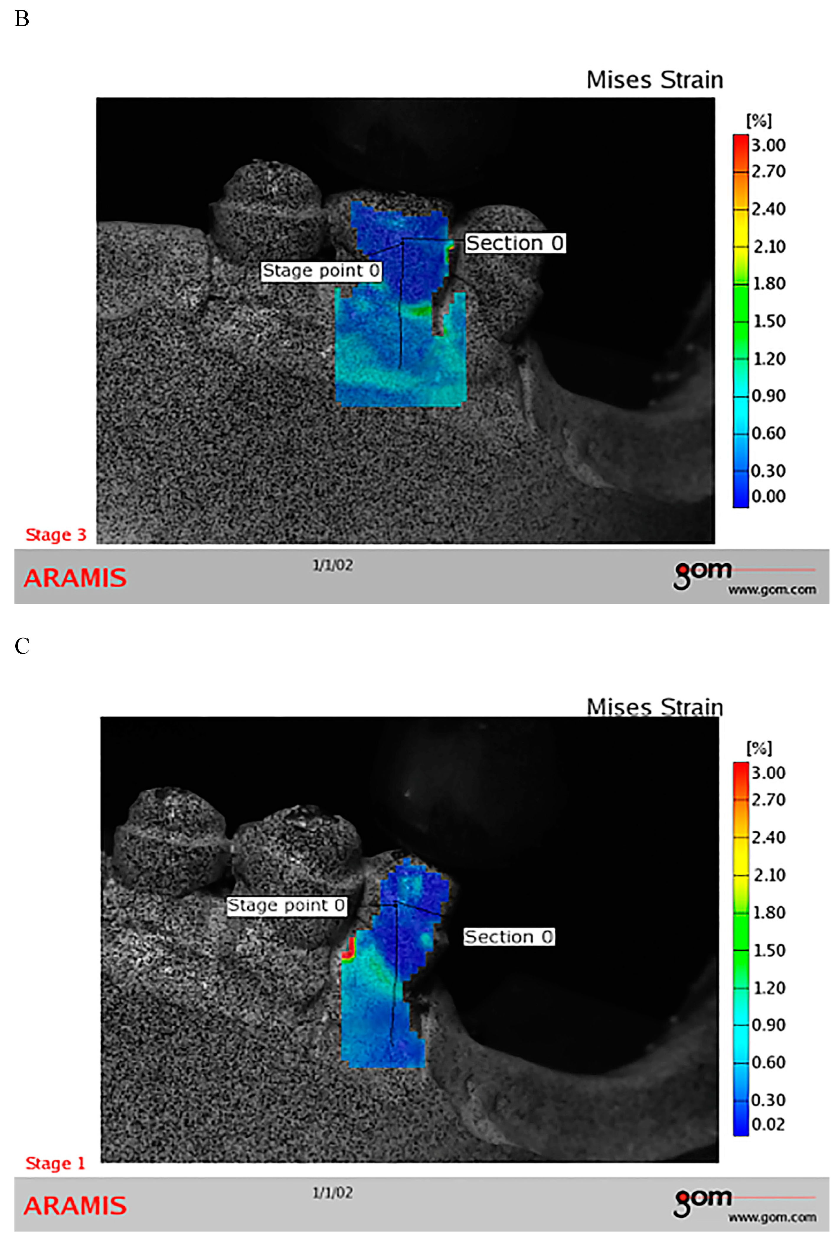
Stress and deformations of the cast copings investigated in the present study were differently distributed. We found that the most intensive deformations occurred under actual force transmitted towards the border of the coping and the immediate area of remaining tooth substance.
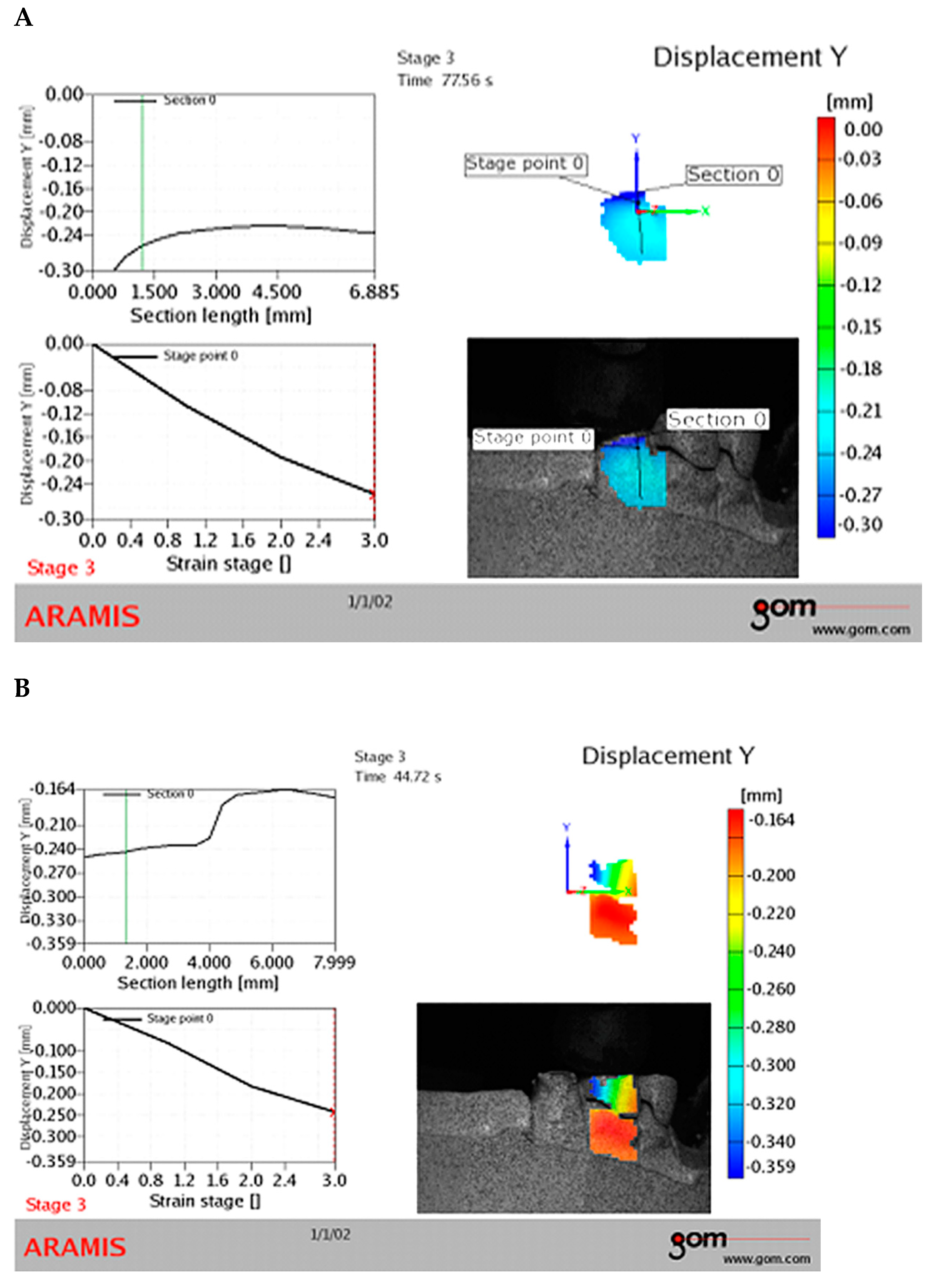
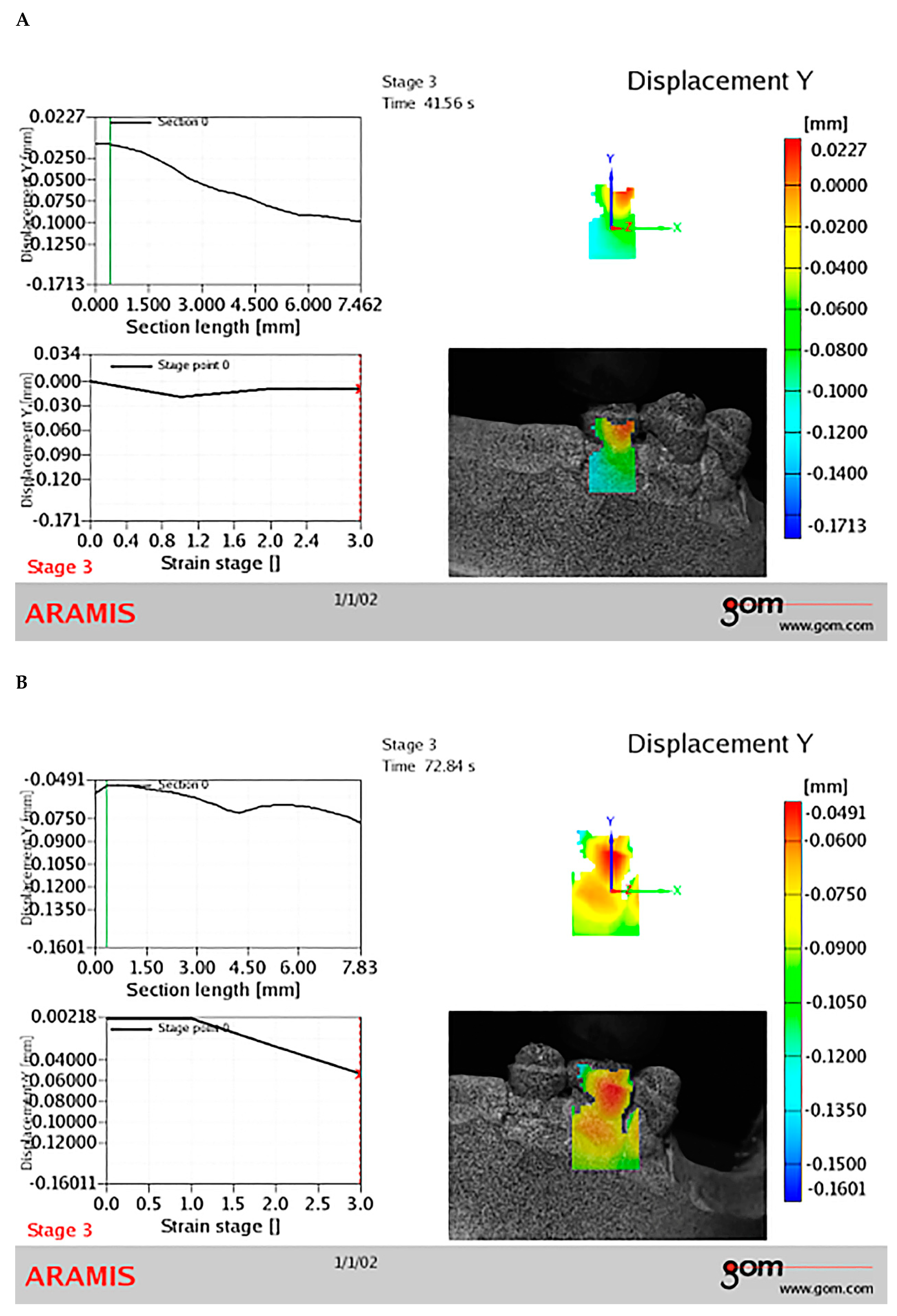
Significantly lower displacements were recorded in the group of teeth with experimental milled copings compared to the control group with rounded copings (
Figure 1 and
Figure 2). These results were consistent across all three loading stages and regardless of the tooth type investigated.
The deformation measures were smaller for the milled copings when compared to the control copings (
Table 1 and
Table 2).
There was a direct link between the percent of coping deformation and the type of coping (p=0.0364) (
Table 3).
The type of the coping was a significant determinant of the degree of displacement of tooth coping under the pressure in this experiment. There was a significant difference in displacement between the control rounded and experimental milled copings (
Table 3).
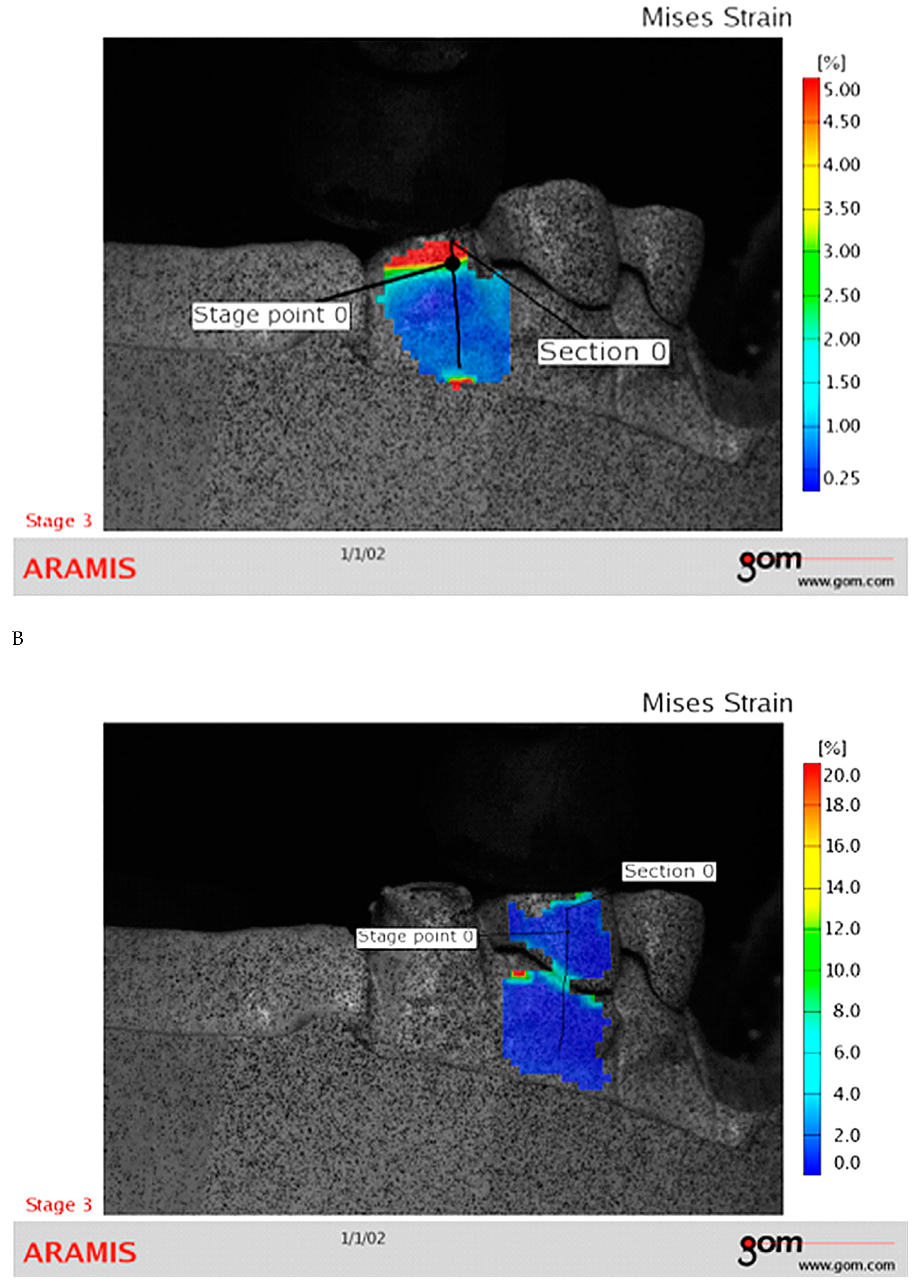
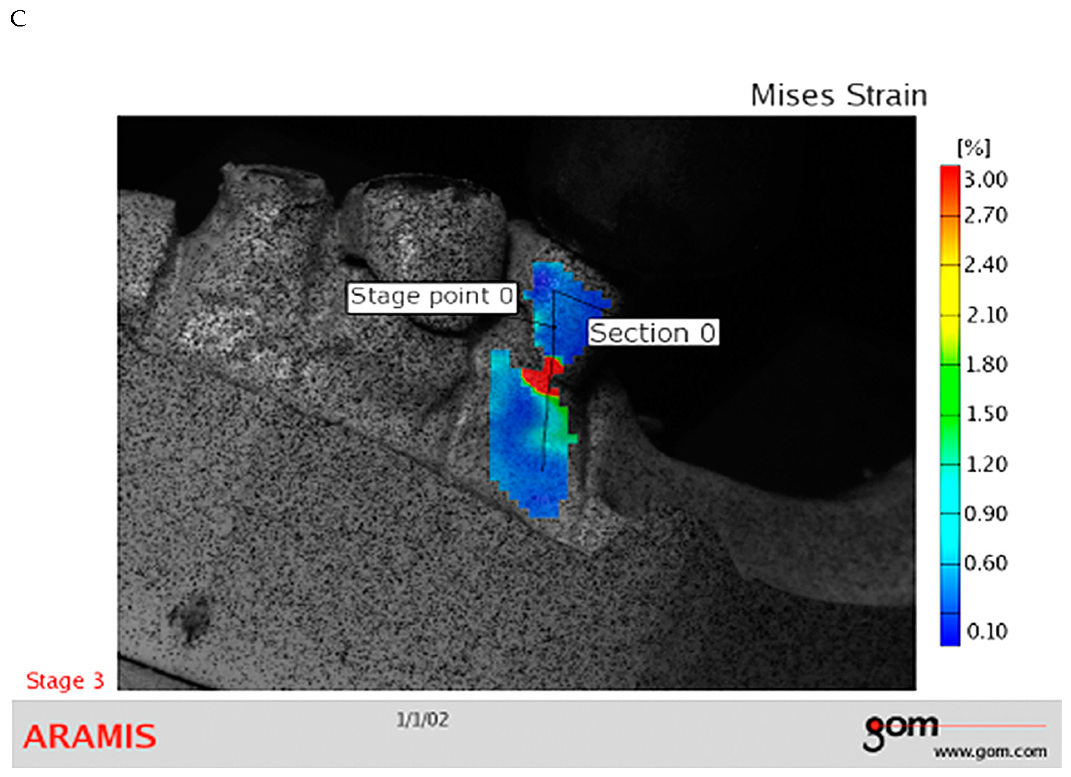
There was significantly greater deformation in the control rounded tooth coping when compared to the experimental milled tooth coping. These findings were provided at pressure stage of 1000 N regardless to the types of teeth evaluated (
Figure 3 and
Figure 4).
Discussion
Presently, overdentures are recommended in cases when a significant number of teeth are absent after multiple extractions from the alveolae.[
1,
2] Conserving alveolar bone and enabling denture stabilization can be achieved by covering remaining teeth with copings. [
2,
3] Moreover, it remains unknown as to why the remaining teeth in our study were present only on one side of the mandible, taking into consideration the well-known consequent problem that remaining tooth substance can undergo ‘additional loading’ as a consequence of the edentulous side of the mandible.
This experiment was performed on a Kennedy class 1 partially-edentulous mandible (i.e. B3 [and C2] classification of Eichner) because this type of partially-edentulous jaw is the most frequently presented in clinical practice. Likewise, this type of partial edentulous is relatively difficult to be therapeutically treated. [
1,
2]
This study exposed significantly higher values of deformation of control rounded copings when compared to the experimental milled ones. Higher values of deformation of rounded copings could be explained by its spherical surface. More precisely, the axial force acting on a spherical surface consists of two components: tangential and normal. The tangential component was the primary cause of distortion in the control rounded-oval copings. However, only axial forces were present in the case of milled copings, which accounted for their noticeably reduced distortion. In our study, displacement was significantly higher with milled copings compared to the control rounded copings. This result could be explained by the fact that all forces applied on milled copings have been distributed axially.
Researchers in prosthodontics have long debated the subject of stability. It is envisaged that the experiential’s morphologically developed occlusal sections dedicated only to milling copings will divert forces accurately towards the axial axis, resulting in a medically advantageous load.. Additionally, it was assumed that practically the occlusal plateau with the largest surface would almost completely accept all loads (both physiological and masticatory). In general all other loads existing within one oro-facial system), while the axial surfaces of dedicated milled copings, with the exception of the shoulder area, would be significantly or completely relieved of tensile stress, as found in a previous study. [
12] The findings from this study did not completely confirm these assumptions, but proved that there was a significantly smaller degree of deformation among the experimental milled copings. In addition to the above, preliminary studies of the findings evaluating therapy using overdentures noted that both patients and the therapist who evaluated the degree of success found that the dentures that rested on the milled dedicated copings of the roots of the remaining retained maxillary teeth were quite stable. Additionally, when compared to the conventional shape of the copings, there was better direct and indirect stabilization of the prosthesis. [
1] Thus, the milled shoulder of the coping may increase the likelihood of additional retention when accepting the basal surface of the overdenture. Based on these findings and the presented stress (
Figure 4 and
Figure 4), we cannot conclude that the milled surfaces accept and amortize (redirect in the axial and in-center directions) the forces acting on the milled copings to the greatest extent. These findings merely showed that the numerical amount of deformation was smaller in the cervical segments of the dedicated milled copings (
Table 1,
Table 2 and
Table 1), than in that of conventional control copings.
The results of this study raise the question of whether the forces, stresses, and deformations were greatest at the top of the coping, distributing the load and applying pressure vertically toward the tooth's root. The present study examined cast copings, and found that the distribution of stress and deformations varied among them. We found that the most intensive deformations occurred under actual force transmitted towards the border of the coping and the immediate area of remaining tooth substance. Considering that tension was highest in the area of the item with the largest diameter, the cause of the most severe deformations in the cervical border of the copings may be attributed to the maximum tension in that location.
Prior researches examining the difficulties in implementing the stereo-optical (stereometric) approach has demonstrated the method's usefulness in some dental specialties. [
13,
14,
15,
16,
17,
18,
19,
20,
21,
22,
23] Using this stereo optic-method, when two cameras are installed, they can provide that the points from two images can be matched and autostereograms can be created using information about corresponding points based on initial separated positions of two cameras. The information on the 3D position of objects can be determined. [
24,
25] Thus, the stereo-optical (stereometric) method seemed to be reliable for assessment of stress and deformations.
The resemblance between the experimental milling copings and constructs based on the ferrule effect concept lends credence to these arguments. It was already shown that fabrication of milled metal copings with the addition of the post emphasizes the beneficial effects of the prevention of the independent flexure tooth or core/post structures. [
5] Such structures are located within the supra-ferrule-margin volume of the tooth; if a force is applied to the tooth the entire supra-ferrule-margin tooth, core, and post complex work as one unit to resist the force. [
1,
26]
The results of our investigation have exposed that control oval copings were less resistant to loading when compared with experimental milled copings. Since this is the first paper to our knowledge in which a stereo-optic examination of the shape of committed copings was conducted, it is very difficult to compare the findings from this study to those from other studies. This is because there are no relevant data on the action of forces and deformations for these purposes.
The high values of the loads (400 N, 800 N, and 1000 N) utilized in this study are addressed in the limitations of this experimental investigation, keeping in mind that the mean occlusal loads on the premolars ranged from 39 to 66 N, and on the front teeth (apart from bruxists) from 11 to 33 N. [
17,
27,
28]
Conclusions
The study's findings will require the adoption of protective copings as extracoronal construction for the teeth that remain underneath overdentures in practice. Based on the results of this study there will be the implicit demand in clinical practice to position protective copings as extracoronal construction of remaining teeth under overdentures. Experimental milled copings are less susceptible to deformation compared to control rounded copings. These findings may have clinical significance in improvements of primary and secondary retention of overdentures on milled copings.
Declarations of interest
none.
Acknowledgments
Authors of the current study wish to expose the sincere gratitude to Professor Dr Taško Maneski, Docent Goran Mladenović , Professor Nenad R. Mitrović, employed in the Faculty of Mechanical Engineering of the University of Belgrade, Serbia, as well as to the dental labor Wisil M – Mila Simonović located in the area of New Beograd, Serbia for their help in the realization of this experiment.
References
- Poštić, S.D. Specially designed copings for stability of overdentures. JSM Dent 2016, 4, 1061–1065. [Google Scholar]
- Ilić, D.; Brković, S.; Poštić, S. Overdenture in terms of preparation and restoration of supporting teeth: Review report. VSP 2020, 77, 1086–1092. [Google Scholar]
- Brković-Popović, S.; Stanišić-Sinobad, D.; Poštić, S.D.; Djukanović, D. Radiographic changes in alveolar bone height on overdenture abutments: a longitudinal study. Gerodontology 2008, 25, 118–223. [Google Scholar] [PubMed]
- Preiskel, H.W. Overdentures made easy: A guide to implant and root supported prostheses; Quintessence Int. Co.: London, 1996; pp. 21–137. [Google Scholar]
- Chhabra, A.; Chhabra, N.; Jain, A.; Kabi, D. Overdenture prostheses with metal copings: A retrospective analysis of survival and prosthodontic complications. J Prosthodont 2019, 28, 876–882. [Google Scholar] [PubMed]
- Mercouriadis-Howald, A.; Rollier, N.; Tada, S.; McKenna, G.; Igarashi, K.; Schimmel, M. Loss of natural abutment teeth with cast copings retaining overdentures: a systematic review and meta-analysis. J Prosthodont Res 2018, 62, 407–415. [Google Scholar]
- The Glossary of Prosthodontic Terms: Ninth Edition. J Prosthet Dent 2017, 117, e1–105.
- Zarb, G.A.; Jacob, R.F.; Zarb, J.P. Overdentures. In Zarb GA, Bolender CL, Eckert ST, et al (eds): Prosthodontic Treatment for Edentulous Patients (ed 12); Mosby: St Louis, 2004; pp. 160–176. [Google Scholar]
- Gul, E.B.; Suca, G.Ç. Finite Element Stress Analysis of Overdentures Supported by Angled Implants. Merit Res J Med Med Sci 2014, 2, 196–206. [Google Scholar]
- Windisch, S.; Jung, R.; Sailer, I.; Studer, S.; Ender, A.; Hämmerle, C. A new optical method to evaluate three-dimensional volume changes of alveolar contours: a methodological in vitro study. Clin Oral Impl Res 2007, 18, 545–551. [Google Scholar]
- Poštić, S.D.; Milošević, M.; Maneski, T.; Mladenović, G.M.; Brković, S.; Trifković, B. Optical stereometric analysis of an experimental partially-edentulous mandible. Advances in Mechanical Engineering 2022, 14. [Google Scholar] [CrossRef]
- Ha, S.R.; Kim, S.H.; Lee, J.B.; Han, J.S.; Yeo, I.S.; Yoo, S.H. Effects of coping designs on stress distributions in zirconia crowns: Finite element analysis. Ceram Int 2016 42, 4932–4940.
- Shahar, R.; Weiner, S. Insights into whole bone and tooth function using optical metrology. J Mat Sci 2007, 42, 8919–8933. [Google Scholar]
- Ahn, B.; Kim, J. Measurement and characterization of soft tissue behavior with surface deformation and force response under large deformations. Med Image Anal 2010, 14, 138–148. [Google Scholar] [PubMed]
- Kulchin, Y.; Vitrick, O.; Lantsov, A.; Vorobyev, A.; Moskvin, Y. Measuring the deformity of dentofacial bone tissues using a speckle correlation method. Optoelectr Instrum Data Process 2008, 44, 264–268. [Google Scholar]
- Durbin, D.M.; Durbin, D.A. Patent US 6364660B1. 6364. Available online: https://patents.google.com/patent/US6364660B1/en.
- Kahn-Jetter, Z.; Chu, T. Three-dimensional displacement measurements using digital image correlation and photogrammic analysis. Exp Mech 1990, 30, 10–16. [Google Scholar]
- Windisch, S.; Jung, R.; Sailer, I.; Studer, S.; Ender, A.; Hämmerle, C. A new optical method to evaluate three dimensional volume changes of alveolar contours: a methodological in vitro study. Clin Oral Impl Res 2007, 18, 545–551. [Google Scholar]
- Tanasić I, Milić-Lemić A, Tihaček-Šojić Lj, Stančić I, Mitrović N. Analysis of the compressive strain below the removable and fixed prosthesis in the posterior mandible using a digital image correlation method. Biomech Model Mechanobiol 2012, 11, 751–758.
- Gubeljak, N.; Kocak, M.; Huther, M.; Valh, T. Fitness-for-service Fracture Module SOFTWARE. FME Transactions 2008, 36, 39–44. [Google Scholar]
- Lovald, S.T.; Wagner, J.D.; Baack, B. Biomechanical optimization of bone plates used in rigid fixation of mandibular fractures. J Oral Maxillofac Surg 2009, 67, 973–985. [Google Scholar]
- Sedmak, A.; Milošević, M.; Mitrović, N.; Petrović, A.; Maneski, T. Digital image correlation in experimental mechanical analysis. Struct Integr Life 2012, 12, 39–42. [Google Scholar]
- Tihaček Šojić Lj, Milić-Lemić A, Tanasić I, Mitrović N, Milošević M, Petrović A. Compressive strains and displacement in a partially dentate lower jaw rehabilitated with two different treatment modalities. Gerodontology 2012, 29, e851-7.
- Yang, H.S.; Park, J.M.; Han, J.S.; Lee, J.B.; Kim, S.H.; Yeo, I.S. Measuring abutment convergence angles using stereovision dental image processing system. J Adv Prosthodont 2014, 6, 259–265. [Google Scholar] [PubMed]
- Bradski, G.R.; Kaehler, A. Learning open CV: computer vision with the open CV library; O’Reilly: Farnham, 2008; p. 555. [Google Scholar]
- Mamoun, J.S. On the ferrule effect and the biomechanical stability of teeth restored with cores, posts and crowns. Eur J Dent 2014, 8, 281–286. [Google Scholar] [PubMed]
- Ye, Y.; Di, P.; Jia, S.; Lin, Y. Occlusal force and its distribution in the position of maximum intercuspation in individual normal occlusion: a cross-sectional study. Zhonghua Kou Qiang Yi Xue Za Zhi. 2015, 50, 536–539. [Google Scholar] [PubMed]
- Hidaka O, Iwasaki M, Saito M, Morimoto T. Influence of clenching intensity on bite force balance, occlusal contact area, and average bite pressure. J Dent Res 1999, 78, 1336–1344.
|
Disclaimer/Publisher’s Note: The statements, opinions and data contained in all publications are solely those of the individual author(s) and contributor(s) and not of MDPI and/or the editor(s). MDPI and/or the editor(s) disclaim responsibility for any injury to people or property resulting from any ideas, methods, instructions or products referred to in the content. |
© 2024 by the authors. Licensee MDPI, Basel, Switzerland. This article is an open access article distributed under the terms and conditions of the Creative Commons Attribution (CC BY) license (http://creativecommons.org/licenses/by/4.0/).
