Preprint
Article

Joint Sensing and Communications in UAV-Assisted Systems

Altmetrics

Downloads

74

Views

37

Comments

0

A peer-reviewed article of this preprint also exists.

Submitted:

30 September 2024

Posted:

30 September 2024

You are already at the latest version

Alerts
Abstract
The application of joint sensing and communications (JSACs) technology in air-ground networks, which include unmanned aerial vehicles (UAVs), offers unique opportunities for improving both sensing and communication performances. However, this type of networks are also sensitive to the peculiar characteristics of the aerial communications environment, which include shadowing and scattering caused by man-made structures. This paper investigates an aerial JSAC network and proposes a UAV-selection strategy that is shown to improve the communication performance. We first derive analytical expressions for the received signal-to-interference ratio for both communication and sensing functions. These expressions are then used to analyze the outage and coverage probability of the communication part, as well as the ergodic radar estimation information rate and the detection probability of the sensing part. Moreover, a performance trade-off is investigated under the assumption of a total bandwidth constraint. The presented results reveal the impact of shadowing severity and interference on the system’s performance.
Keywords: 
Subject: Engineering  -   Telecommunications

1. Introduction

Joint sensing and communication (JSAC) technology has been proposed as an efficient solution that allows wireless communication and radar sensing coexistence in the same system. The research for JSAC technology has recently gained an increased interest in an effort to effectively exploit the same radio and hardware resources for both sensing and communication functions [2,3]. However, the competition for resources (such as limited power, spectrum, antennas, or other hardware components) between the sensing and communication functions presents a significant challenge that needs to be addressed. It is crucial to identify the key performance boundaries and trade-offs between these functions in JSAC systems subject to resource competition.
In the last few years, various contributions exist that investigate the performance of JSAC systems, e.g., [4,5,6,7]. In [4], an integrated sensing and communication (ISAC) system was proposed, in which a micro base station (BS) that can simultaneously conduct target sensing and cooperative communication is assumed, under a non-orthogonal downlink transmission scenario. In this context, various performance metrics such as outage probability (OP), communication rate, and sensing detection probability (DP) were analyzed. In [5], a comparison between sensing-communication coexistence (SCC) and JSAC designs utilizing non-orthogonal downlink transmission and transmit antenna selection was performed. Under the assumption of residual hardware impairments and imperfect successive interference cancellation, the performance of the schemes under consideration was evaluated based on the criteria of exact and asymptotic OPs and the probability of successful target detection. In [6], the performance tradeoff within distributed ISAC networks was analytically evaluated based on the tools of stochastic analysis and stochastic geometry. Through these analytical findings, a detailed presentation of the performance boundaries and trade-offs between sensing and communication within a distributed ISAC network was given. In [7], a collaborative ISAC network was investigated that exploits coordinated beamforming techniques. In this framework, the signal-to-interference ratio (SIR) statistics were investigated in order to evaluate the spectral efficiency of the proposed scheme.
Unmanned aerial vehicles (UAVs) have been adopted as an efficient approach for improving coverage probability, in various application scenarios, especially when fast deployment is required [8]. Their undoubtedly benefits is the main reason why UAVs have been also adopted in JSAC scenarios in order to exploit the synergy between these two technologies for more efficient use of onboard resources, resulting in improved overall performance [9]. To this aim, recently a numerous of contributions have been presented, which investigate JSAC in UAV-assisted communication scenarios, e.g., [10,11,12,13]. In [10], a collaborative JSAC and UAV assisted network is proposed, in which beam sharing opportunities are adopted. In this context, a novel upper-bound average cooperative sensing area performance metric is also proposed, which illustrated the performance improvement of the investigated strategy. In [11], cellular UAV assisted network is considered, in which communication operations are performed jointly with sensing. In this context, the collision probability is analytically investigated taking into account the radar cross section (RCS) characteristics. In [12], an air-ground JSAC network was examined, which involves unmanned aerial vehicles (UAVs) and ground terrestrial networks. For this important communication scenario, the system architecture and protocol design were explored for four potential use cases, followed by an analysis of Air-Ground JSAC (AG-JSAC) network characteristics and advantages. In [13], the network layer delay violation is analyzed in an ISAC and UAV assisted communication scenario. Among other investigations the successful sensing probability was analytically studied. A common characteristic of the previously presented results is that the shadowing effects have not been taken into account, despite the fact that, in aerial communication networks, the effect of large scale fading is dominant.
Motivated by this observation, in this paper, we consider an aerial-JSAC communication network operating over a generic channel model, in which the impact of large scale fading is also taken into account. In this type of networks, the radio signals transmitted by a UAV-BS, after having traveled through free space, encounter in an urban environment, arrive at the destination. In this urban setting, the signals experience shadowing and scattering due to man-made structures, resulting in extra loss for the air-to-ground link. Therefore, we consider a UAV-selection strategy that offers improved performance with reduced complexity, as compared to benchmarks. For this scheme, we derive exact expressions for the statistics of the received SIR, which are then used to investigate the OP, the coverage probability (CP), the DP and the ergodic radar estimation information rate (EREIR). Moreover, the DP and CP performance trade-off with the respect to the bandwidth that is used for these operations is also investigated. The numerical results presented depict the impact of the shadowing parameter values and the number of interfering signals on the system’s performance.
The remainder of this paper is organized as follows. In Section II, the system model of the JSAC aerial network and the corresponding channel model are provided. In Section III, the analytical framework for obtaining the performance measures for both JSAC operations is presented. In Section IV, the simulation settings are given and based on them various numerical evaluated results are discussed. Finally, this paper’s conclusions are drawn in Section V.

2. System and Channel Models

We consider a JSAC UAV-assisted communication network, in which one out of L UAVs, which operate as aerial BSs, is selected to communicate with the destination receiver, as depicted in Figure 1. Moreover, UAVs are also responsible for sensing the surrounding environment in order to identify specific targets. Here, the investigation focuses on the downlink for the communication operation. However, similar results are expected to be available for the uplink performance. A bandwidth division principle between sensing and communication operations is assumed. It is noted that the basic outcomes of the paper are also valid for the scenario, where time division approach is employed. During the sensing phase, each of the available UAVs transmits a sensing signal in order to identify the target. On the other hand, at the communication phase, the selected UAV communicates with the target receiver. However, in both the destination and the UAV radars, interfering signals are also received due to transmissions and echoes from surrounding UAVs.

2.1. Channel Model

For the aerial channel model both the effects of small scale fading and large scale fading (shadowing) are taken into account. More specifically, Nakagami-m distribution is considered, which has been found to provide an excellent fit to the fading conditions observed in UAV-to-ground scenarios [14]. The probability density function (PDF) of the random variable g, that models the Nakagami-m distributed channel gain, is given by [15, eq. (2.20)]
f g ( x ) = m m x m 1 Ω m Γ ( m ) exp m x Ω ,
where m is distribution’s shaping parameter, related to the severity of the fading, Ω denotes the mean square value, and Γ ( · ) is the gamma function [16, eq. (8.310/1)]. The corresponding CDF expression is given by
F g ( x ) = γ ( m , m x Ω ) Γ ( m ) ,
where γ ( · , · ) denotes the lower incomplete gamma function [16, eq. (8.350/1)]. It is noted that is type of shadowing modeling is directly related to the probability of obtaining line of sight propagation conditions between the two ends of communication [17].
As far as the shadowing effects are concerned, they appear due to the presence of large scale obstacles between the UAVs and the receiver. These shadowing random fluctuations are modeled by the inverse gamma (IG) distribution with PDF given by [14]
f s j ( y ) = γ ¯ j α j Γ ( α j ) y α j + 1 exp γ ¯ j y ,
where α j > 1 is the shaping parameter of the distribution, related to the severity of the shadowing, i.e., lower values of α j result in lighter shadowing conditions, and γ ¯ j denotes the scaling parameter. Moreover, the CDF of s j is given by
F s j ( y ) = Γ ( α j , γ ¯ j y ) Γ ( α j ) ,
where Γ ( · , · ) denotes the upper incomplete gamma function [16, eq. (8.350/2)].
As far as the sensing operation is concerned, the received echo signal at a UAV is given by [18]
P e c h = p s G t G r λ 2 σ ( 4 π ) 3 d 2 ν ,
where p s denotes the transmitting power of the sensing signal, G t and G r denote the transmitting and receiving antenna gains, respectively, λ is the wavelength of the sensing signal, d denotes the distance between the sensing target and the UAV, ν is the path loss factor, and σ is the cross-section of the target. The latter one is a random variable, since it fluctuates from scan to scan, and it follows the Swerling type-1 model, whose PDF is given by [19]
f σ ( σ ) = 1 σ ¯ exp σ σ ¯ , σ 0 ,
where σ ¯ is the average cross section over all target fluctuations.

2.2. Communication Model

As far as the communication part is concerned, it is assumed that the UE is connected to the UAV that is less exposed to the shadowing effects. Moreover, assuming that the noise level is relatively small as compared to the aggregate interference, we focus on the interference limited scenario. Under this UAV-selection policy and based on the approach initially proposed in [20], the received SIR can be expressed as
γ c = p c G t G r g s max d ν I c ,
where p c denotes the transmit power at the communication phase and s max = max { s 1 , s 2 , , s L } denotes the maximum shadowing coefficient from the L available UAV-receiver links. Moreover, I c = i = 1 M p c G t G r h 1 , i 2 d i ν denotes the aggregate interference term, with h 1 , i being the channel gains for the downlink and d i is the distance between the i-th, i = 1 , . . . , M interfering UAV and the receiver.

2.3. Sensing Model

During the sensing phase, the detection decisions are conducted by using the target echo power P e c h . Based on this approach the received SIR at the UAV that senses the target is given by [6]
γ s = P e c h I s ,
where I s = i = 1 M A e S h 1 , i 2 h 2 , i 2 d i ν denotes the aggregate interference term, h 1 , i and h 2 , i , i = 1 , . . . , M , denote channel gains that follow Nakagami-m fading, A e = G r λ w 2 4 π denotes the effective receiving antenna aperture and S = p s G t 4 π denotes the power density from an interfering UAV.

3. Performance Analysis

For the communication part, the performance of the system under investigation will be investigated using the criteria of the OP and the CP, while for the sensing part, the performance metrics that will be employed are the EREIR and the DP. The CP is defined as the probability that the achievable transmission capacity is above a predefined threshold γ th , i.e.,
P C = P ( γ c > 2 γ th B c 1 ) ,
where B c denotes the bandwidth allocated for communication purposes. Based on the CP criterion, the OP is defined as P out = 1 P C . Moreover, the EREIR is defined as [6]
R B = δ 2 T log 2 1 + 2 T B s γ s ,
where T denotes the pulse duration, B s denotes the bandwidth allocated for sensing purposes, and δ denotes the radar duty cycle. Based on the EREIR, the criterion of DP is defined as follows
P D = Pr [ R B > γ th ] = Pr γ s > 2 2 T γ th δ 1 2 T B s ,
where γ th denotes the detection threshold.

3.1. Communication Operation

For evaluating the performance of the scheme under consideration, the behavior of the received SIR is statistically evaluated. To this aim, let us define the random variable Y = g I c . The PDF and CDF of Y are, respectively, given by
f Y ( y ) = 0 x f g ( y x ) f I c ( x ) d x
F Y ( y ) = 0 F g ( y x ) f I c ( x ) d x .
The statistics of I c are provided in Appendix A. Substituting (1) and (A3) in (12) and using the definition of the gamma function [16, eq. (8.310)], yields the following analytical expression for the PDF of Y
f Y ( y ) = C k = 0 δ k Γ ( ρ + k ) β 1 ρ + k m m Ω m Γ ( m ) y m 1 1 β 1 + y Ω k m ρ .
As far as the CDF of Y is concerned, substituting (2) and (A3) in (13), using [16, eq. (6.455)] and after some mathematical manipulations, yields the following expression
F Y ( y ) = C k = 0 δ k Γ ( ρ + k ) β 1 ρ + k y Ω m Γ ( ρ + k + m ) m Γ ( m ) × 2 F 1 1 , ρ + k + m ; m + 1 ; y / Ω y / Ω + 1 / β 1 1 β 1 + y Ω k m ρ ,
where 2 F 1 ( · ) denotes the Gauss hypergeometric function [16, eq. (9.100)].
For evaluating the final CDF of γ c , the statistics of s max are required, which are provided in Appendix B. Therefore, using (14) and (A8) in (13), results to the following type of integral
I = 0 y x m 1 1 β 1 + y x Ω k m ρ exp γ ¯ M x γ ¯ x ξ d x ,
where ξ = i = 0 α 1 i n i + 1 , with n i s denoting integers related to the multiple sums presented below. In order to evaluate this integral, the Meijer G-function representations of the constitute functions are employed, using [21], as follows
1 β 1 + y x Ω k m ρ = 1 β 1 k m ρ 1 Γ ( k + m + ρ ) G 1 , 1 1 , 1 β 1 y x Ω | 1 k m ρ 0 , exp γ ¯ M x = G 1 , 0 0 , 1 γ ¯ M x | 0 ,
where G m , n p , q · | · denotes the Meijer G-function. Based on these expressions, using [21, eq. (21)] and after some analysis, results to
F γ c ( x ) = C k = 0 n 1 = 0 M n 2 = 0 M n α = 0 M n 1 + n 2 + + n α = M γ ¯ c x ξ M ! n 1 ! n 2 ! n α ! δ k Γ ( m + k + ρ ) i = 0 α 1 1 i ! n i + 1 × Γ ( m + ξ ) Γ ( k ξ + ρ ) Γ ( m + k + ρ ) β 1 Ω m ξ 1 F 1 m + ξ , 1 k + ξ ρ , M γ ¯ c Ω β 1 x Γ ( k + ξ ρ ) M γ ¯ c x k ξ + ρ β 1 Ω 1 m k ρ F 1 m + k + ρ , 1 + k ξ + ρ , M γ ¯ c Ω β 1 x ,
where 1 F 1 ( · ) denotes the confluent hypergeometric function [16, eq. (9.210/1)], while γ ¯ c = γ ¯ p c G t G r d ν .

3.2. Sensing Operation

For evaluating the sensing performance, the statistical behavior of the corresponding received SIR is evaluated. To this aim, let us define the random variable W = σ I s . For evaluating the PDF of W, a similar procedure to the one used in the derivation of (14) is adopted, resulting to
f W ( y ) = C k = 0 δ k σ ¯ Γ ( ρ + k ) β 1 ρ + k 1 β 1 + y σ ¯ k 1 ρ .
The corresponding CDF can be derived as
F W ( y ) = C k = 0 δ k Γ ( ρ + k + 1 ) 1 1 + β 1 y σ ¯ k 1 ρ .
Based on (19), the PDF of γ s can be directly evaluated using a change of variables of the form W = γ s ( 4 π ) 3 d 2 ν p s G t G r λ 2 , which results to a similar expression to (19), where σ ¯ is substituted with γ ¯ σ = σ ¯ p s G t G r λ 2 ( 4 π ) 3 d 2 ν . For evaluating the expression for the EREIR, (19) should be substituted in (10). Following such an approach, integrals of the following form need to be solved
I 2 = 0 1 β 1 + x γ ¯ σ k 1 ρ log 2 1 + 2 T B s x d x .
Using again the Meijer-G function representations for the functions in (21), i.e., using [21]
ln ( 1 + x ) = G 1 , 2 2 , 2 x | 1 , 1 1 , 0 ,
as well as [21], yields the following exact expression
R B = δ 2 T C k = 0 δ k / ln ( 2 ) Γ ( ρ + k ) Γ ( 1 + k + ρ ) G 2 , 3 3 , 3 2 B s T γ ¯ σ β 1 | 1 , 1 , 0 1 , k + ρ , 0 .
It is noted that with a small number of terms, i.e., < 20 , a satisfactory accuracy is observed, i.e., which guarantees accuracy better than ± 0.5 % , in all infinite series expressions derived in this paper.

3.3. Performance Trade-Off

In the system under consideration, the performance trade-off between the sensing and communication functions can be analyzed. One of the key factors that influences this trade-off is to allocate different portions of the frequency spectrum to the sensing and communication functions. In this frequency-division approach, part of the total bandwidth is dedicated to transmitting the sensing waveform, while the remaining portion is used for transmitting the communication signal. This leads to a bandwidth allocation trade-off, which can be expressed as follows [22]
B s + B c = B .
In the numerical results section, we investigate the performance trade-off between communication and sensing functions when we allocate different portions of the total available bandwidth B to B c and B s .

4. Numerical Results

In this section, based on the analytical results derived previously, several numerical evaluated results are presented and discussed. If not otherwise stated, in the simulation results, the parameter values depicted in Table 1 are assumed.
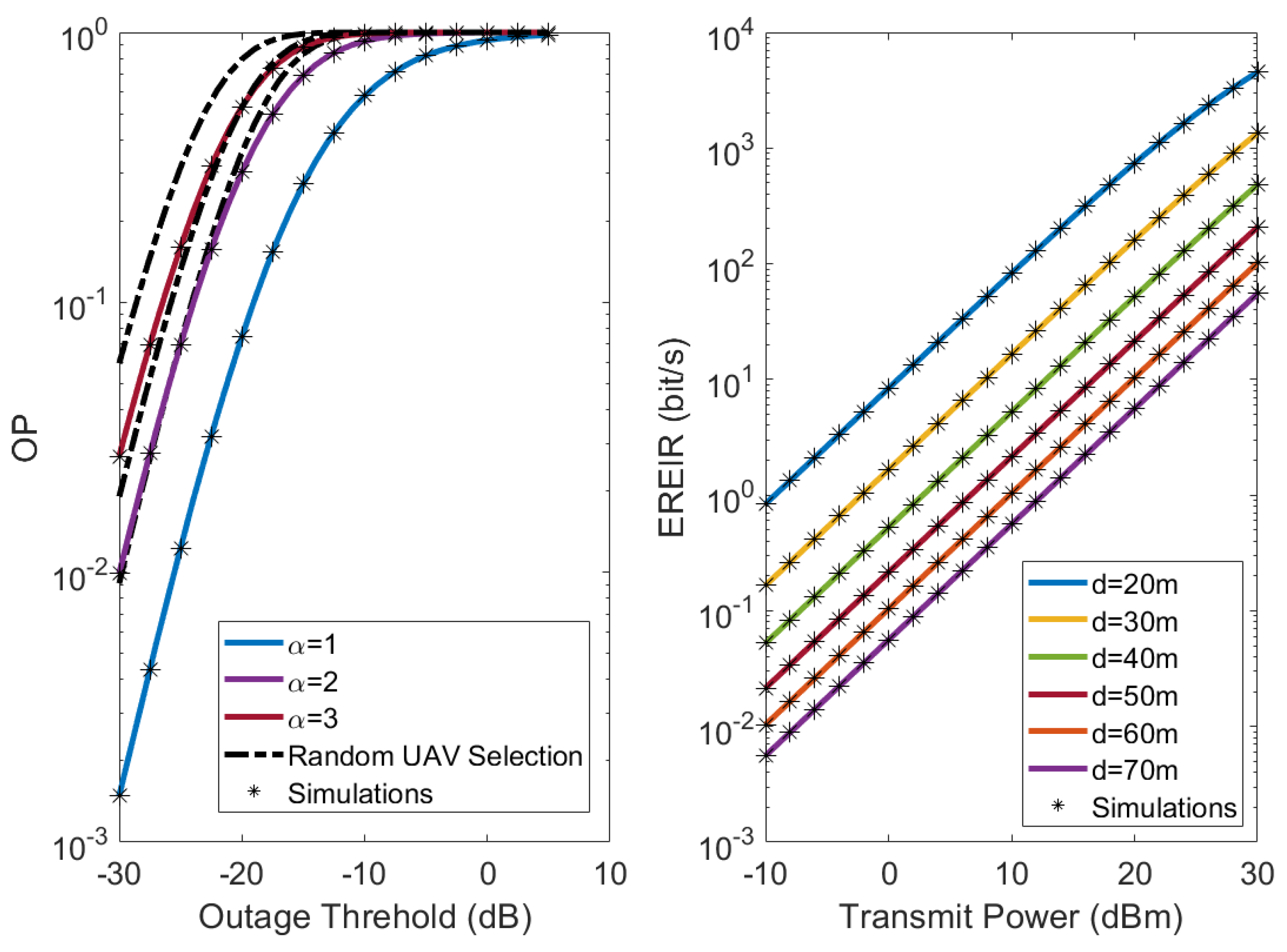
In Figure 2, the OP and DP performances have been evaluated. More specifically, in the left subplot, the OP using UAV selection is plotted as a function of the outage threshold γ th , for various values of the shadowing coefficients α = α j , j = 1 , . . . , L . It is shown that for the same γ th , almost ten times less OP is observed when light shadowing conditions are assumed, i.e., α = 1 , compared to moderate shadowing, α = 3 . In the same figure, for comparison purposes, the performance of a scheme without UAV-selection is also presented. It is shown that the performance of the UAV-selection scheme is considerably improved, especially in the case of severe shadowing conditions. In the right subplot of Figure 2, the EREIR is plotted as a function of the transmit power for different distances of the radar target. The plot shows the performance degradation of the sensing operation as the distance increases.
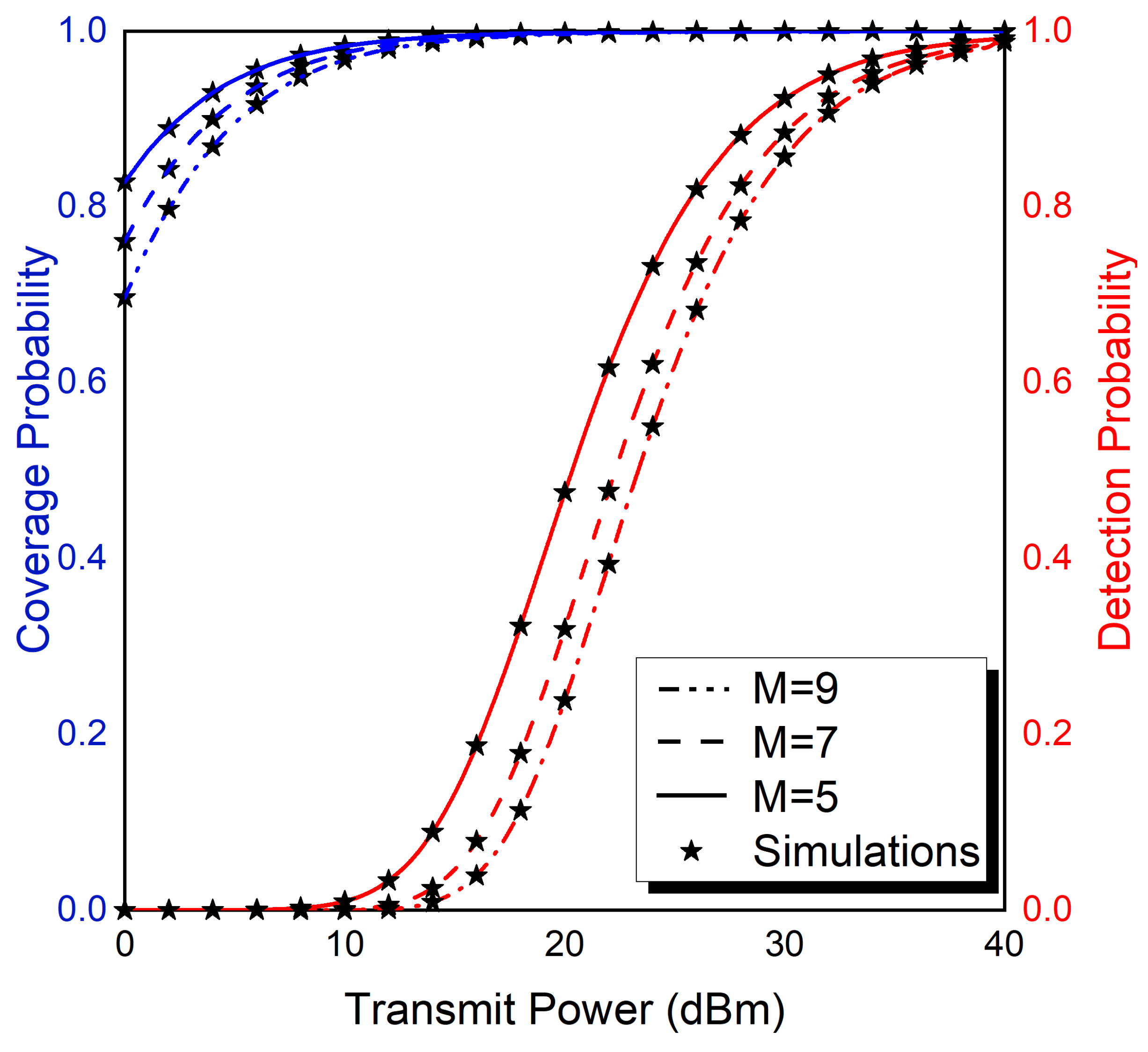
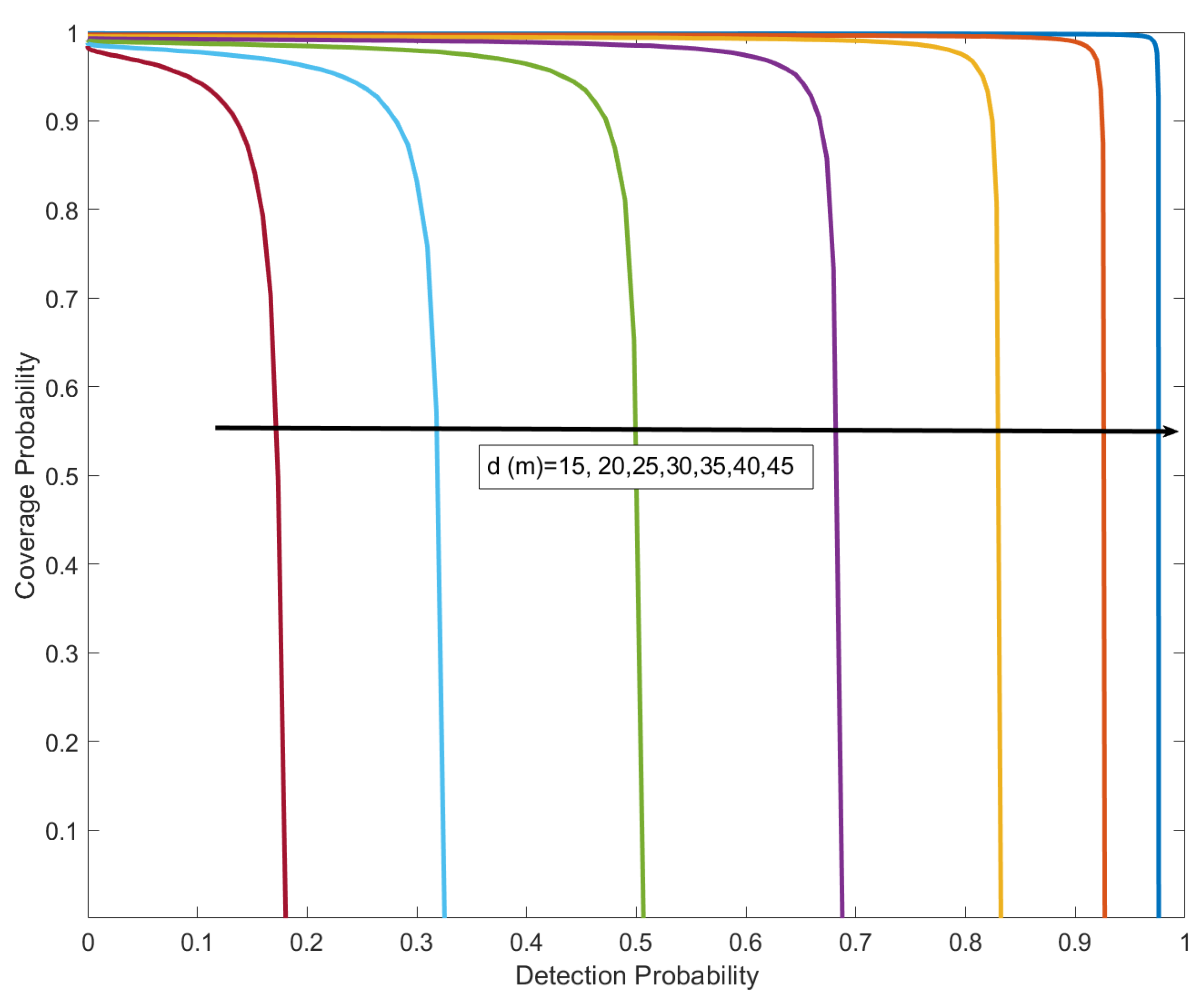
In Figure 3, we investigate the effect of aggregate interference by plotting the coverage probability (with γ th = 0 d B ) and the DP of the sensing operation as a function of the transmit power, for different values of the number of interfering signals. It is shown that the number of interfering signals has an important influence on the performance of both operations, which reduces as M increases. One of the main results of this paper is illustrated in Figure 4, in which the fundamental performance trade-off between communication and sensing functions under specific bandwidth constraint, i.e., B = 20 MHz, is presented. It is noted that the sum of the bandwidths B c and B s is limited by the total available one B and thus it is impossible to simultaneously obtain optimal performance for both these functions. However, a useful balance can be achieved as it will be depicted in Figure 4. In this figure, it is shown that as the communication bandwidth B c increases, the CP also increase, but DP decreases, since a reduction on B s is required in order to satisfy the fixed total bandwidth. The results also show that the variations in the bandwidth have a greater impact on the communication performance than on sensing. For example, as B c reduces from 20 MHz to 0, which results in an increase of B s from 0 to 20 MHz), the CP drops from 1 to 0, while DP increases from 0 to 0.2, as shown by the yellow curve. In the same figure, it is also illustrated that as the distance between the UAV and the destination/target d increases, the impact of the modification of the B s at the DP increases. Finally, it is noted that in all figures presented, simulations results have been also included, verifying the validity of the presented analytical framework.

5. Conclusions

In this paper, a new UAV selection strategy is proposed for an aerial JSAC network operating in a composite fading environment. To this aim, we presented an analytical framework used to evaluate the coverage probability of the scheme under consideration and the EREIR of each UAV. The presented results revealed the impact of shadowing and interference on the system’s performance. It was shown that a performance trade off exist in frequency division JSAC scenarios. Moreover, the numerical results presented revealed that the performance of the communication function can be considerably improved using a shadowing based UAV selection policy. Our next steps include an analytical investigation in a more general scenario in which the impact of the noise and the antenna patterns will be also taken into account.

Author Contributions

Conceptualization, P.B. and A.K.; methodology, P.B.; software, P.B. and K. M.; investigation, P.B. and G. E.; writing—original draft preparation, P.B.; writing—review and editing, K. M., G.E. and A. K.; All authors have read and agreed to the published version of the manuscript.

Funding

This work was co-funded by University of Piraeus Research Centre and the EU HORIZON programme under iSEE-6G GA No. 101139291.

Conflicts of Interest

The authors declare no conflicts of interest.

Abbreviations

The following abbreviations are used in this manuscript:
CDF Cumulative distribution function
CP Coverage probability
DP Detection probability
EREIR Ergodic radar estimation information rate
ISAC Integrate sensing and communication
JSAC Joint sensing and communication
OP Outage probability
PDF Probability density function
SIR Signal to interference ratio
SNR Signal to noise ratio
UAV Unammned aerial vehicle

Appendix A. Statistics of the Sum of Gamma RVs

In this appendix, a convenient exact expression for the PDF of the aggregate interference terms for the communication function is presented. Let us assume that RV I i is defined as follows
I i = p c G t G r h 1 , i 2 d i ν .
Here, RV I i is approximated by a gamma RV G i , whose shaping and scaling parameters can be evaluated using the moment matching method, e.g., [23]. Based on this assumption, I i is now represented by a sum of M gamma RVs given as follows
I q = G 1 + G 2 + + G M ,
where q { s , c } . Based on the results presented in [24], the PDF of I q can be expressed as follows
f I q ( x ) = C k = 0 δ k x ρ + k 1 Γ ( ρ + k ) β 1 ρ + k exp x β 1 ,
where β i = Ω i m i , β 1 = m i n ( β i ) , while
C = i = 1 M β 1 β i m i , ρ = i = 1 M m i , γ k = i = 1 M m i k 1 β 1 β i k
δ k + 1 = 1 k + 1 i = 1 k + 1 i γ i δ k + 1 i , k = 0 , 1 , 2 ,
with δ 0 = 1 . It is noted that the same analytical steps have been followed for approximating the aggregate interference term of the sensing function.

Appendix B. Statistics of the Maximum of Inverse Gamma RVs

In this appendix, a simplified expression for the CDF of s max is presented. Assuming independent and identically distributed shadowing conditions, i.e., α j = α and γ ¯ j = γ ¯ , and based on probability laws, the CDF of s max is given by
F s max ( y ) = [ F s ( y ) ] M = Γ ( α , γ ¯ y ) Γ ( α ) M .
Assuming integer values for the shaping parameter α and using [16, eq. (8.352/2)], (A6) can be written as
F s max ( y ) = exp γ ¯ M y i = 0 α 1 γ ¯ y i 1 i ! M .
Finally, using the multinomial identity [25, eq. (24.1.2)] and after some mathematical simplifications yields
F s max ( y ) = exp γ ¯ M y n 1 = 0 M n 2 = 0 M n α = 0 M n 1 + n 2 + + n α = M M ! n 1 ! n 2 ! n α ! i = 0 α 1 1 i ! n i + 1 γ ¯ y i = 0 α 1 i n i + 1 .

References

  1. Bithas, P.S.; Efthymoglou, G.P.; Kanatas, A.G.; Maliatsos, K. UAV Selection in Aerial Integrated Sensing and Communication Networks. In Proceedings of the IEEE 100th Vehicular Technology Conference (VTCFall); 2024. [Google Scholar]
  2. Wild, T.; Braun, V.; Viswanathan, H. Joint design of communication and sensing for beyond 5G and 6G systems. IEEE Access 2021, 9, 30845–30857. [Google Scholar] [CrossRef]
  3. Xiao, Z.; Zeng, Y. Waveform Design and Performance Analysis for Full-Duplex Integrated Sensing and Communication. IEEE J. Sel. Areas Commun. 2022, 40, 1823–1837. [Google Scholar] [CrossRef]
  4. Liu, M.; Yang, M.; Li, H.; Zeng, K.; Zhang, Z.; Nallanathan, A.; Wang, G.; Hanzo, L. Performance analysis and power allocation for cooperative ISAC networks. IEEE Internet Things J. 2022, 10, 6336–6351. [Google Scholar] [CrossRef]
  5. Liu, M.; Yang, M.; Zhang, Z.; Li, H.; Liu, F.; Nallanathan, A.; Hanzo, L. Sensing-Communication Coexistence vs. Integration. IEEE Trans. Veh. Technol. 2023, 72, 8158–8163. [Google Scholar] [CrossRef]
  6. Li, X.; Guo, S.; Li, T.; Zou, X.; Li, D. On the Performance Trade-Off of Distributed Integrated Sensing and Communication Networks. IEEE Wirel. Commun. Lett. 2023, 12, 2033–2037. [Google Scholar] [CrossRef]
  7. Meng, K.; Masouros, C.; Chen, G.; Liu, F. BS Coordination Optimization in Integrated Sensing and Communication: A Stochastic Geometric View. arXiv preprint arXiv:2401.04918, arXiv:2401.04918 2024.
  8. Wu, Q.; Xu, J.; Zeng, Y.; Ng, D.W.K.; Al-Dhahir, N.; Schober, R.; Swindlehurst, A.L. A comprehensive overview on 5G-and-beyond networks with UAVs: From communications to sensing and intelligence. IEEE Journal on Selected Areas in Communications 2021, 39, 2912–2945. [Google Scholar] [CrossRef]
  9. Zhang, Y.; Shan, H.; Chen, H.; Mi, D.; Shi, Z. Perceptive mobile networks for unmanned aerial vehicle surveillance: From the perspective of cooperative sensing. IEEE Vehicular Technology Magazine 2024. [Google Scholar] [CrossRef]
  10. Chen, X.; Feng, Z.; Wei, Z.; Gao, F.; Yuan, X. Performance of joint sensing-communication cooperative sensing UAV network. IEEE Transactions on Vehicular Technology 2020, 69, 15545–15556. [Google Scholar] [CrossRef]
  11. Tropkina, I.; Sun, B.; Moltchanov, D.; Pyattaev, A.; Tan, B.; Dinis, R.; Andreev, S. Distributed communication and sensing system co-design for improved UAV network resilience. IEEE Transactions on Vehicular Technology 2022, 72, 924–939. [Google Scholar] [CrossRef]
  12. Fei, Z.; Wang, X.; Wu, N.; Huang, J.; Zhang, J.A. Air-ground integrated sensing and communications: Opportunities and challenges. IEEE Communications Magazine 2023, 61, 55–61. [Google Scholar] [CrossRef]
  13. Mei, M.; Yao, M.; Yang, Q.; Wang, J.; Jing, Z.; Quek, T.Q. Network-layer Delay Provisioning for Integrated Sensing and Communication UAV Networks under Transient Antenna Misalignment. IEEE Transactions on Wireless Communications 2024. [Google Scholar] [CrossRef]
  14. Bithas, P.S.; Nikolaidis, V.; Kanatas, A.G.; Karagiannidis, G.K. UAV-to-Ground communications: Channel modeling and UAV selection. IEEE Trans. Commun. 2020, 68, 5135–5144. [Google Scholar] [CrossRef]
  15. Simon, M.K.; Alouini, M.S. Digital Communication over Fading Channels, 2 ed.; Wiley: New York, 2005. [Google Scholar]
  16. Gradshteyn, I.S.; Ryzhik, I.M. Table of Integrals, Series, and Products, 6 ed.; Academic Press: New York, 2000. [Google Scholar]
  17. Al-Hourani, A.; Kandeepan, S.; Lardner, S. Optimal LAP altitude for maximum coverage. IEEE Wireless Commun. Lett. 2014, 3, 569–572. [Google Scholar] [CrossRef]
  18. Ren, P.; Munari, A.; Petrova, M. Performance tradeoffs of joint radar-communication networks. IEEE Wirel. Commun. Lett. 2018, 8, 165–168. [Google Scholar] [CrossRef]
  19. Fang, Z.; Wei, Z.; Chen, X.; Wu, H.; Feng, Z. Stochastic geometry for automotive radar interference with RCS characteristics. IEEE Wirel. Commun. Lett. 2020, 9, 1817–1820. [Google Scholar] [CrossRef]
  20. Bithas, P.S.; Kanatas, A.G.; Matolak, D.W. Exploiting shadowing stationarity for antenna selection in V2V communications. IEEE Trans. Veh. Technol. 2018, 68, 1607–1615. [Google Scholar] [CrossRef]
  21. Adamchik, V.S.; Marichev, O.I. The algorithm for calculating integrals of hypergeometric type functions and its realization in REDUCE system. In Proceedings of the Proc. Int. Conf. on Symbolic and Algebraic Computation, Tokyo, Japan; 1990; pp. 212–224. [Google Scholar]
  22. Li, X.; Feng, G.; Sun, Y.; Qin, S.; Liu, Y. A Unified Framework for Joint Sensing and Communication in Resource Constrained Mobile Edge Networks. IEEE Transactions on Mobile Computing 2023, 22, 5643–5656. [Google Scholar] [CrossRef]
  23. Bithas, P.S.; Ropokis, G.A.; Karagiannidis, G.K.; Nistazakis, H.E. UAV-Assisted Communications With RIS: A Shadowing-Based Stochastic Analysis. IEEE Trans. Veh. Technol. 2024. [Google Scholar] [CrossRef]
  24. Moschopoulos, P.G. The distribution of the sum of independent gamma random variables. Annals of the Institute of Statistical Mathematics 1985, 37, 541–544. [Google Scholar] [CrossRef]
  25. Abramowitz, M.; Stegun, I.A. Handbook of mathematical functions: with formulas, graphs, and mathematical tables; Vol. 55, Courier Corporation, 1964.
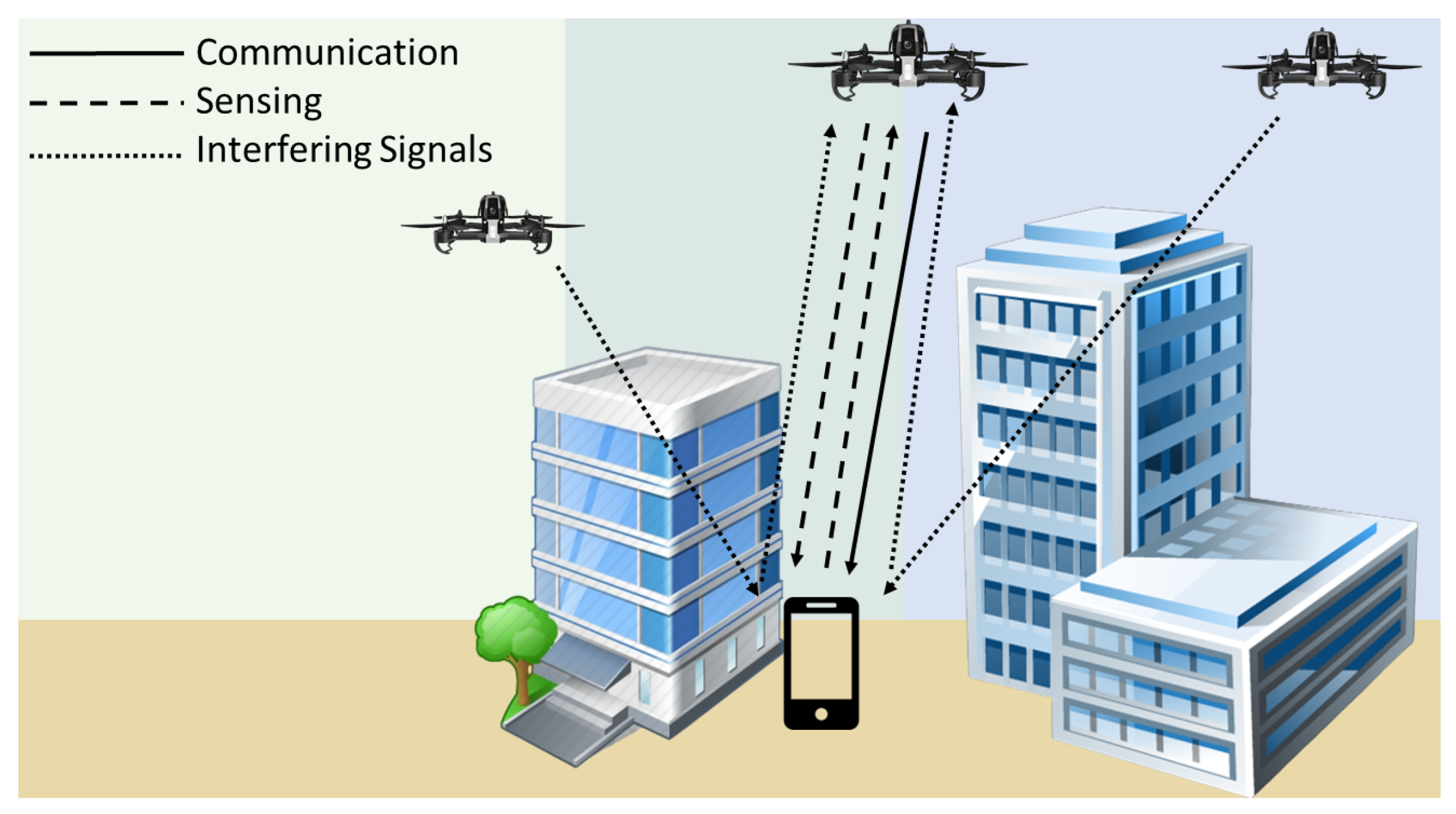
Figure 1. System model of the considered JSAC scheme.
Preprints 119803 g001
Figure 2. Communication Function: OP vs the outage threshold. Sensing Function: EREIR vs transmit power.
Preprints 119803 g002
Figure 3. Coverage Probability and Detection Probability vs transmit power for different number of interfering sources.
Preprints 119803 g003
Figure 4. Coverage Probability and Detection Probability trade-off under bandwidth allocation for different distances.
Preprints 119803 g004
Table 1. Simulation Parameters Values.
Communication Parameters Values
Wavelength ( λ ) 0.0833 m
Transmit Power ( P c ) 15dBm
Tx Antenna Gain ( G t ) 10dB
Rx Antenna Gain ( G r ) 10dB
Tx-Rx Distance (d) 80m
Path Loss Factor ( ν ) 2
Number of Interfering Signals (M) 9
Nakagami Parameter (m) for all links 2
Number of UAVs (L) 4
Bandwidth ( B c ) 20MHz
Sensing Parameters Values
Bandwidth ( B s ) 20MHz
Pulse Duration (T) 1 μ sec
Radar Duty Cycle ( δ ) 0.01
Disclaimer/Publisher’s Note: The statements, opinions and data contained in all publications are solely those of the individual author(s) and contributor(s) and not of MDPI and/or the editor(s). MDPI and/or the editor(s) disclaim responsibility for any injury to people or property resulting from any ideas, methods, instructions or products referred to in the content.
Copyright: This open access article is published under a Creative Commons CC BY 4.0 license, which permit the free download, distribution, and reuse, provided that the author and preprint are cited in any reuse.
Prerpints.org logo

Preprints.org is a free preprint server supported by MDPI in Basel, Switzerland.

Subscribe

© 2024 MDPI (Basel, Switzerland) unless otherwise stated