2.1. Premise of Analysis: The Maximum Anisotropy of the Speed of Light is Not Strictly Equal to Zero
Our analysis is grounded on the premise that the maximum anisotropy of the speed of light, measured as
in the Michelson-Morley experiment[
9], is indeed small, but not strictly equal to zero. We hypothesize that the true factor may be concealed under the assumption that this small but non-zero value of the maximum anisotropy of the speed of light reflects the underlying physical reality.
Based on the Pythagorean Theorem, the relationship between
t and
can be expressed by the following equation:
According to Equation (
1), for
, the following relational equation is satisfied:
Figure 1.
The red dotted lines depict the dimensions of the object as observed in the moving frame M, where h represents the dimension perpendicular to the direction of motion and w represents the dimension along the direction of motion. The blue solid lines illustrate the shape of the object as observed in the rest frame R under the scaling effects of special relativity. Here, is the dimensional scaling factor in the direction of motion, and is the scaling factor perpendicular to the direction of motion, with and under the Lorentz factor. The angle is between the light ray observed by observer M and the velocity of motion, ranging from , and it is not affected by velocity-induced scaling, as the object’s size remains constant to the observer in the moving frame. Points and D represent the same location on the moving object. Point is where the light ray reaches as observed by observer M in the moving frame along the , and point D is where the light ray reaches as observed by observer R in the rest frame under the scaling effect. The variable t denotes the time for light to travel from O to D as recorded by the clock R in the rest frame, and is the time for light to travel from to as recorded by the clock M in the moving frame.
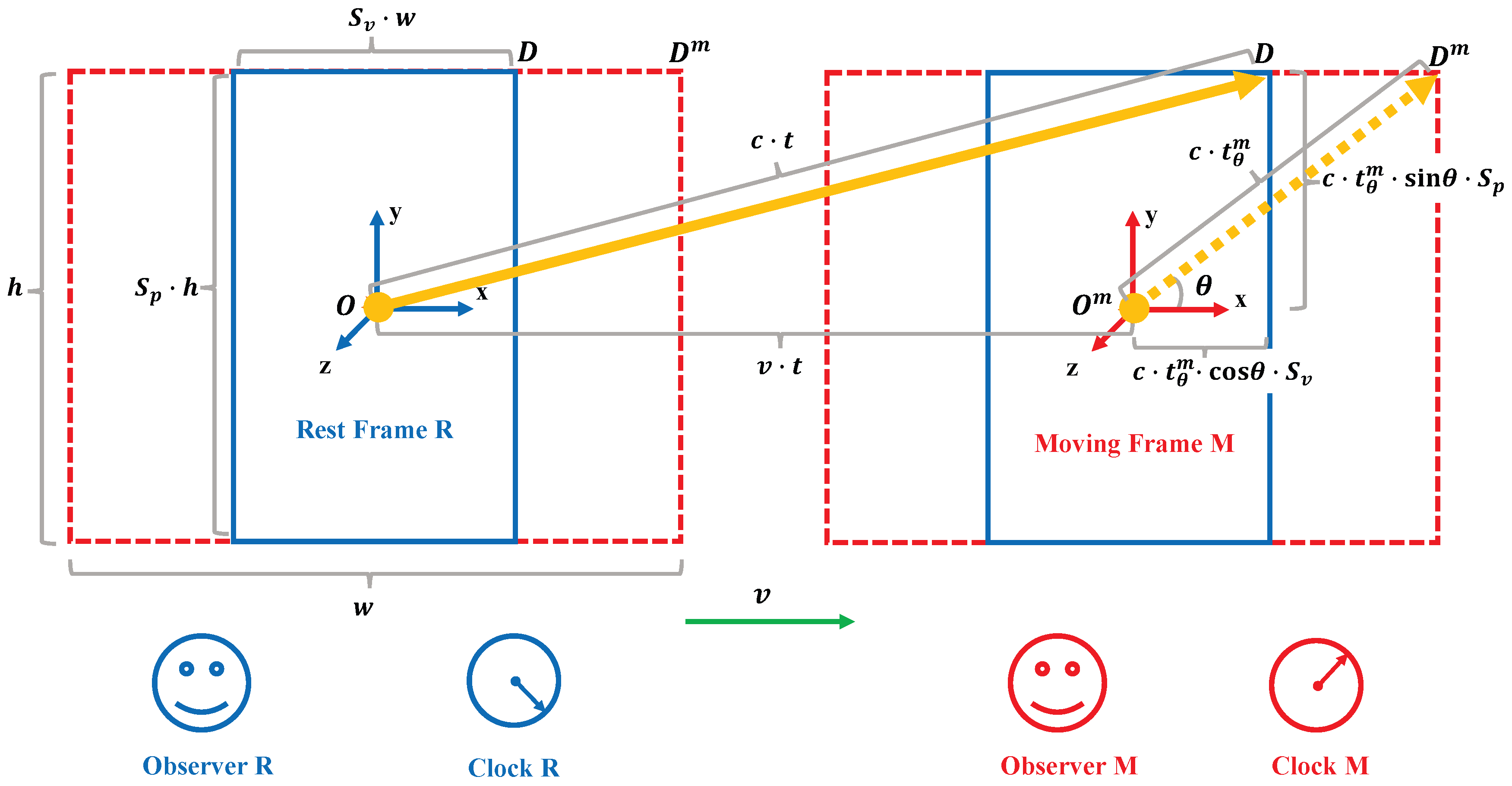
where the angle is defined as the angle between the direction of light propagation as observed by the observer M within the moving frame and the velocity of the object. This angle ranges from 0 to and is not affected by the scaling effect due to changes in the object’s speed, as the object’s size remains constant to the observer M in the moving frame. When , the direction of light propagation is the same as the direction of the object’s motion. Conversely, when , the direction of light propagation is entirely opposite to the direction of the object’s motion. It is important to note that the angles and represent the same physical situation, both corresponding to the angle .
We define the unidirectional time scaling factor between
and
t as
, where:
The unidirectional time scaling factor characterizes the relative passage of time for different directions within a moving object. Notably, signifies complete stasis of time in the direction characterized by angle . Values of correspond to a slowdown in the passage of time, while indicates no relative change. Conversely, suggests an acceleration of time in that specific direction.
To understand the time dilation effect, it is essential to define a clock as a timekeeping instrument based on periodic reciprocating motion. This principle underlies all clocks, whether mechanical, electronic, or atomic. In a mechanical clock, the periodic motion is provided by a pendulum or balance wheel, which drives the clock’s gears and hands. An electronic clock relies on the oscillation of a quartz crystal, which vibrates at a precise frequency when an electric current is applied, converting these vibrations into electrical impulses for timekeeping. In an atomic clock[
10,
11], vibrations of atoms like cesium or rubidium, when exposed to an electromagnetic field, oscillate at a highly stable frequency, making atomic clocks the most accurate.
Applying this principle to the analysis of time dilation, we introduce the Einstein Light Clock[
2,
4], which is a theoretical apparatus for measuring time intervals based on the behavior of light. It consists of two mirrors separated by a fixed distance
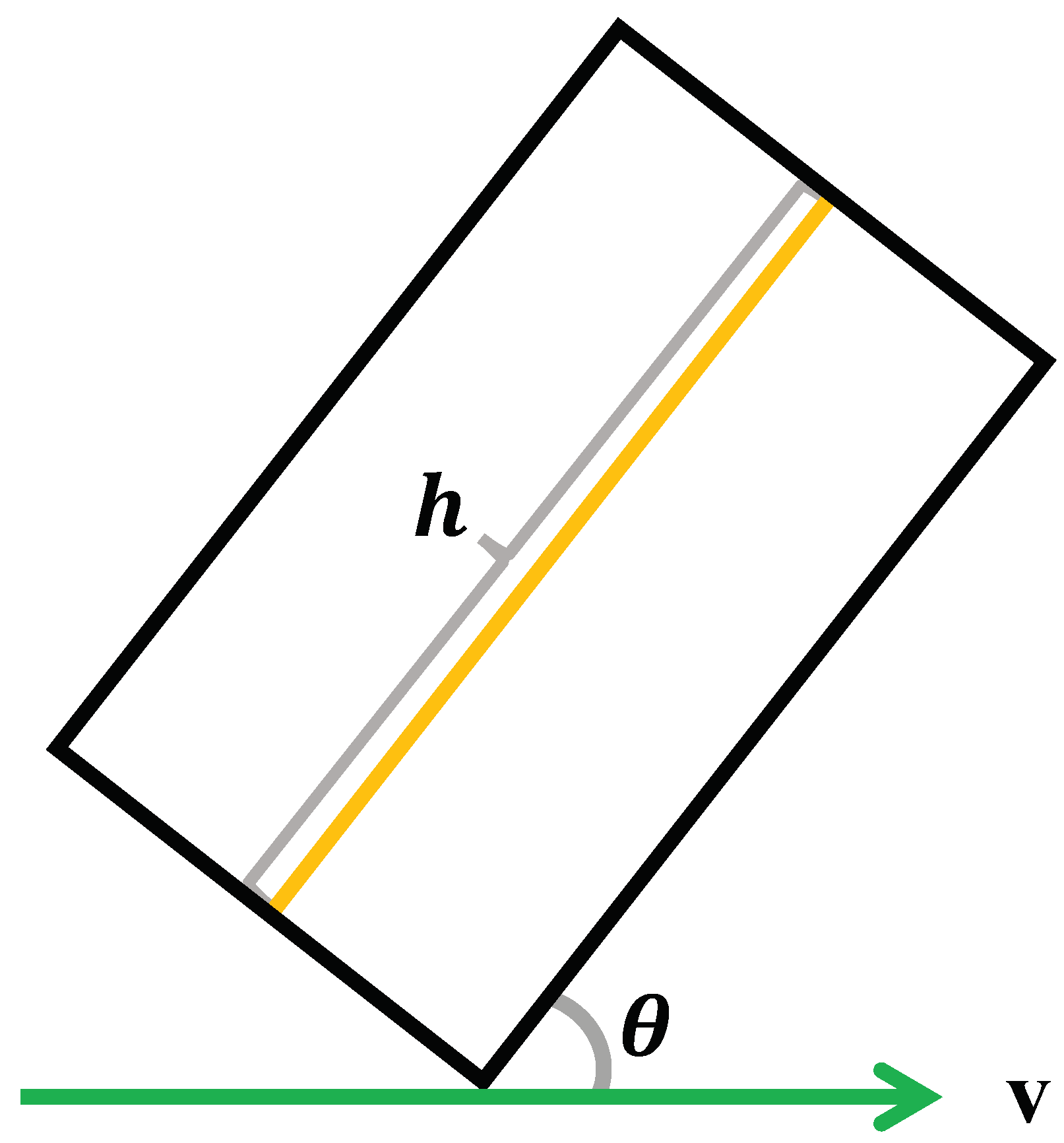
h, which is the distance light travels from one mirror to the other in a light clock. A beam of light travels from one mirror to the other and back again, completing a round trip. Each round trip constitutes one "tick" of the clock. This setup allows time to be measured based on the number of ticks the light completes between the mirrors. To analyze the relationship between the time dilation effect and the
angle, we consider placing the light clock at a
angle to the direction of motion, as shown in Fig.
Figure 2. Here,
ranges from 0 to
. When light propagates from one mirror to the other at an angle
, it returns from the other mirror to the starting mirror at an angle
. This placement allows for examining how the effect of time dilation on the light clocks varies with
.
When the light clock in the moving frame is positioned at an angle
to its direction of velocity, the time interval for each tick of the light clock in the moving frame can be measured in two different frames of reference. The time interval measured in the rest frame is denoted as
, and the time interval measured in the moving frame is denoted as
. These intervals can be expressed respectively as follows:
The time scaling factor of the light clock
, which represents the ratio of the time intervals measured by the clocks in the moving frame and the rest frame, is defined as follows:
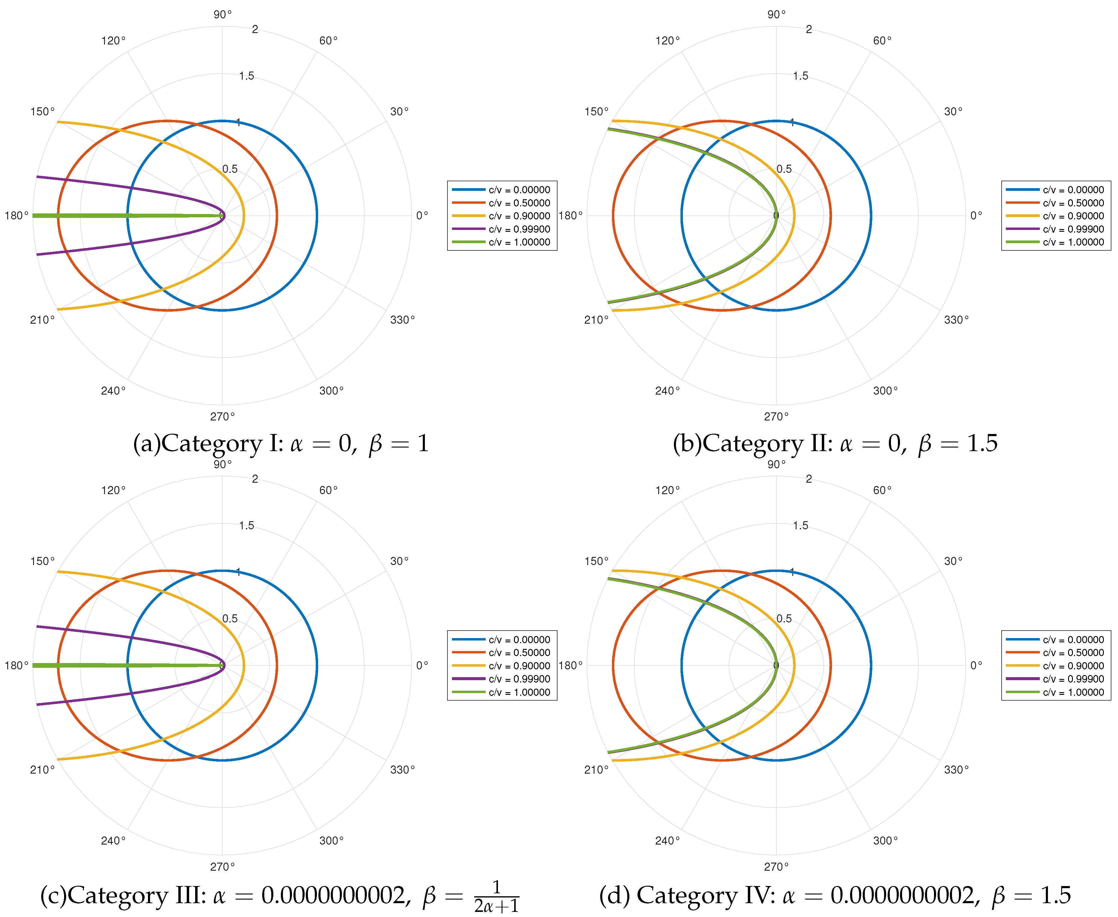
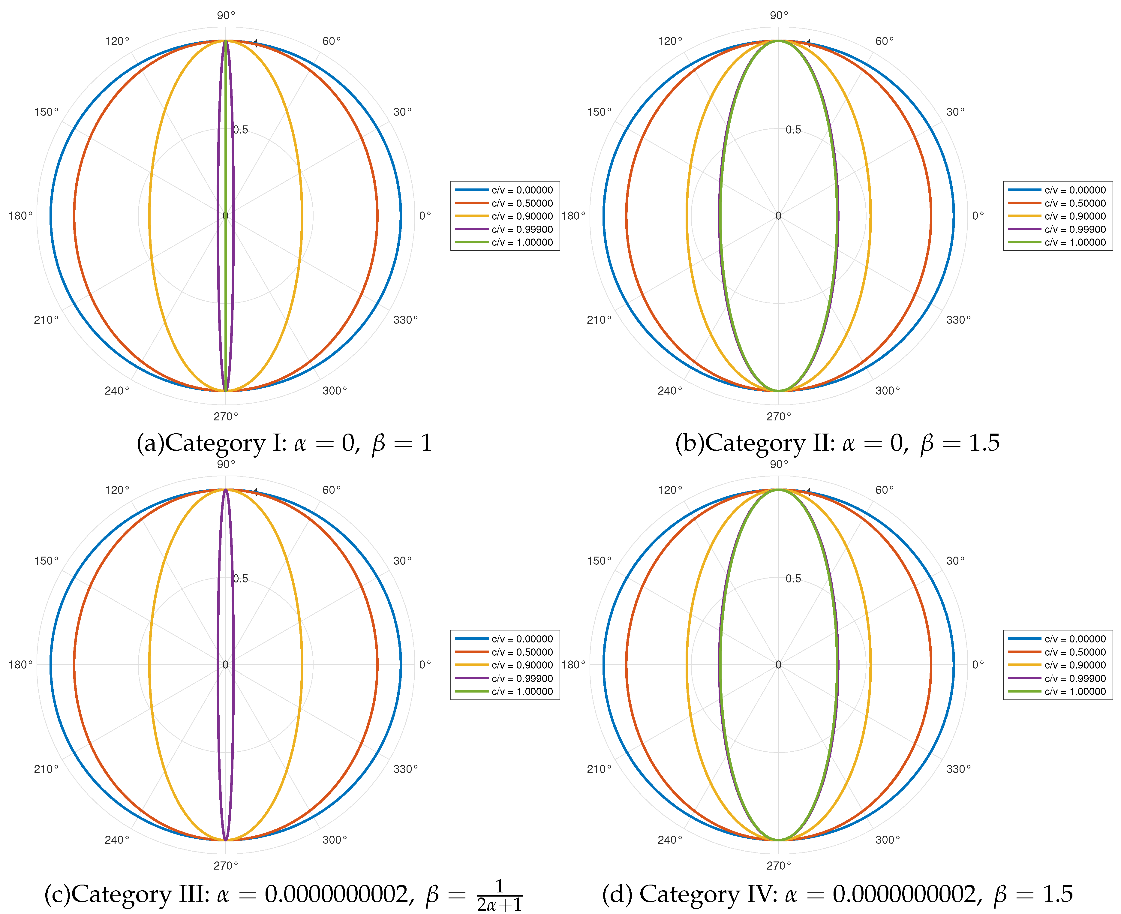
The time scaling factor of the light clock is related to both the velocity v of the moving object and the angle . The correlation with the velocity v reflects the time dilation effect on moving objects as described by special relativity. Specifically, the time dilation’s effect on a light clock depends on the angle , demonstrating how the effect of time dilation on the light clock is distributed in three dimensions within a moving frame.
When the time scaling factor of the light clock , the time of the light clock in that direction is completely stationary. When , the time of the light clock in that direction slows down. When , the time of the light clock in that direction is no relative change in time compared to the rest frame.
A noteworthy aspect of the light clock’s operation arises when and . In this scenario, light traveling along direction within the clock can propagate from one mirror to the other. However, the return path along becomes impossible. This effectively traps the light, preventing it from completing a full round trip (tick) within the clock. Consequently, the displayed time freezes, appearing to the rest frame observer as a completely static clock ().
It’s crucial to emphasize that this time stasis on the light clock does not contradict the ability of photons to propagate along when within the moving frame. The halted clock reading signifies a standstill in the timekeeping mechanism, not the cessation of light propagation in all directions. Notably, in directions corresponding to , light propagation can be remains feasible.
According to Equation (
6), the time dilation’s effect varies when the light clock is placed at different angles
along the direction of motion within the moving frame. To eliminate the variation in time dilation’s effect caused by different
angles in three-dimensional space inside the moving frame, and to ensure a comprehensive consideration of the time scaling factor of the light clock
, we introduce a consensus time scaling factor of the light clock. This factor is determined by placing a light clock in each direction indicated by the uniformly distributed arrows from the origin to the external three-dimensional space, as illustrated in
Figure 3. The mean value of the time scaling factors from all these light clocks is then taken to establish the consensus time scaling factor of the light clock, denoted as
. This consensus time scaling factor of the light clock satisfies the following expression:
By substituting formula (
6) into formula (
7), we obtain the expression for the consensus time scaling factor of the light clock
as follows:
where
The consensus time scaling factor of the light clock aligns with the principles of atomic clocks [
10,
11], which depend on the isotropic absorption and emission of photons during atomic vibrations. These vibrations occur uniformly in three dimensions, ensuring consistent and reliable timekeeping. Thus, applying a similar comprehensive consideration to the time scaling factor of the light clock in the three-dimensional space of a moving frame ensures more accurate and uniform time measurement, as supported by the three-dimensional isotropic properties fundamental to atomic clocks.
2.2. Compatibility of New Kinetic energy Formulae with Newtonian Mechanics at Low Velocities
Given that Newton’s kinetic energy equation[
1] has been extensively validated at velocities much less than the speed of light and serves as a crucial foundation for analyzing the motion of objects at such velocities, any accurate and comprehensive kinetic energy equation proposed to replace Newton’s kinetic energy equation must fulfil the condition that their approximate solutions at low velocities align with Newton’s kinetic energy equation[
12]. This ensures continuity and consistency in the understanding of motion laws across different velocity regimes.
According to Einstein’s derivation based on the Lorentz factor in special relativity [
4], the time scaling factor between the running time of the light clock within the moving frame and that of the light clock within the rest frame, denoted by
, satisfies the following expression:
where
is the Lorentz factor.
In special relativity, the total energy (
E) of an object with mass
m moving with velocity
v is given by:
The rest energy (
) of the object (the energy when it is at rest) is:
The relativistic kinetic energy (
) is the total energy minus the rest energy:
Newton’s classical kinetic energy formula (
) is:
This formula is derived under the assumption that velocities are much smaller than the speed of light (
c), which means:
The formula (
15) confirms that the relativistic kinetic energy reduces to the Newtonian form at low velocities, thereby ensuring consistency between the two theories. Consequently, any valid consensus time scaling factor of the light clock must satisfy this precondition to uphold Newton’s kinetic energy equation at low velocities, as stated in the flowing equation (
16). The formula (
15) must still hold after replacing
with
:
The formula (
8) can be solved by substituting it into Equation (
16). After substituting formula (
8) into formula (
16), the expressions for
and
can be derived as follows:
where
and
are real numbers that satisfy the flowing conditions:
All possible combinations of
and
that satisfy the constraints outlined in equations (
17)–(
20) can be categorized as follows:
and
2.3. Compatibility to the Maximum Anisotropy in the Speed of Light Measured in the Michelson-Morley Experiment
We further refine the potential range of valid factors by requiring that the maximum anisotropy of the speed of light, as derived from these factors, be consistent with current experimental results. According to the Michelson-Morley experiment, with the Earth revolving around the Sun at a velocity
v of 30 kilometers per second, the minimum measured value of the maximum anisotropy of the speed of light
on Earth is approximately
, which means
. Under these conditions, we know that
satisfies the following expression:
In the scenario where
, the value of
can be determined using the following expression:
Considering that the Earth orbits the Sun at a velocity of
kilometers per second and taking
, it is possible, according to equation (
22), to determine that
.
By substituting
and
kilometers per second into equation (
21), the numerical solution for
, denoted as
, is obtained. Specifically, when
, the solution yields
.
Upon further analysis, considering that the maximum anisotropy of the speed of light predicted by this factor aligns with current experimental measurements, the previously identified range of
and
values has been refined. The updated range is given by
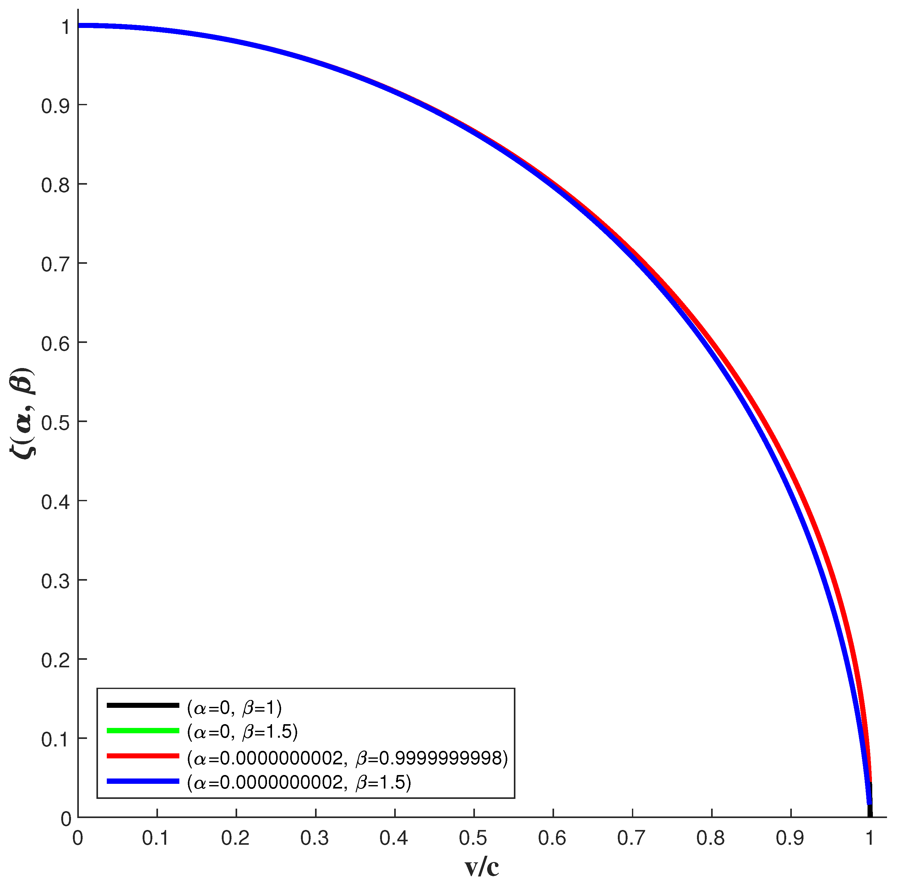
. Based on the distinct scaling effects, the combinations of
and
are categorized into the four primary groups presented in
Table 1.

