1. Introduction
Fully hydrogen-fueled internal combustion engines (ICE) are an essential part of the world’s race to decarbonize our future. Hydrogen, as an easily electrical-produced, completely carbon-free fuel, is a smart way to store the energy needed for remote power consumption, like in marine applications. Hydrogen combustion in internal combustion engine is a technology strongly awaited, but still with major challenges to takle. There are plenty of combustion anomalies like preignition, backfire, knock and lube oil ignition that come along with the technology, hence not yet controllable. Those combustion anomalies were investigated in detail in experiments of [
3,
4] at NMA. To gain more knowledge about their origin, optical engines are a well established method to investigate and develop knew combustion processes. Nowadays CFD simulations are another approach to gain deep insights into those proceedings. Simulation works well at standard thermodynamic engines, but what about simulating an oil-free optical engine. The usually used simulation approaches don’t fit exactly to this engine type. It’s often said, that optical engines suffer from a major mass loss through blow-by [
1,
5,
6]. But how do we quantify this to get the mass balanced for the CFD calculations? This article gives an overview about some approaches [
1,
5,
7] and the differences in optical engine design that might be important for proper modeling. Not only the mass loss is addressed, but also the thermodynamic differences of optic materials compared to standardly used ones [
2,
8,
9,
10]. In the Institute of Sustainable Mobile Powertrains [
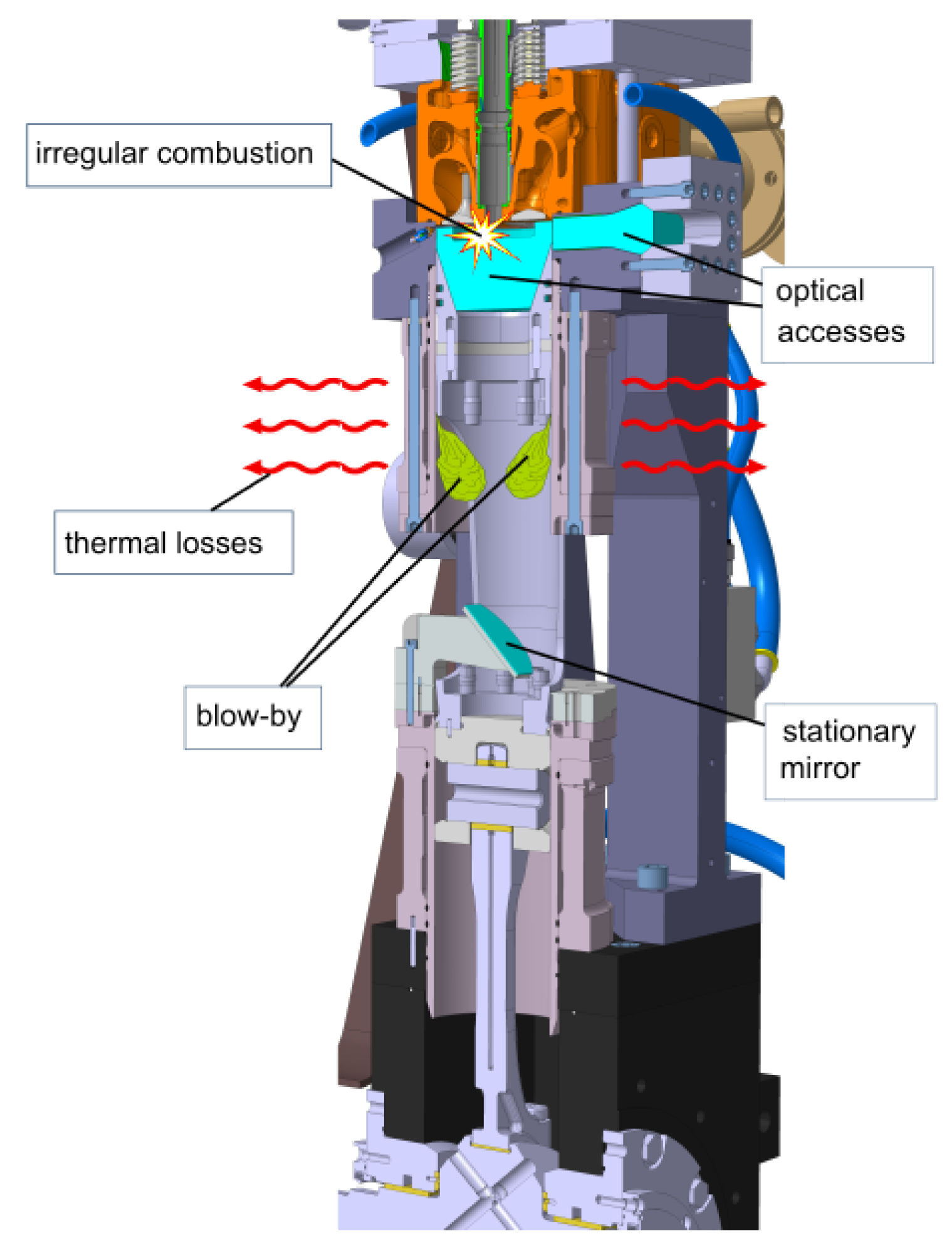
2] describes the losses in gap volumes that are much larger in optical engines, as shown in
Figure 1. A third point is the differing properties of the fuel hydrogen itself, addressed by [
11,
12,
13,
14,
15]. An exciting approach to address these challenges is taken by [
16,
17] by reducing the wall heat loss through load stratification. This works well in this specific test environment. Still, for engine use, more developments must be made in optical engines and CFD simulation of hydrogen combustion to access this urgently needed technology for carbon neutrality.
2. Materials and Methods
During this work, appropriate simulation techniques for the fully optical research engine of the Institute of Sustainable Mobile Powertrains (NMA) were systematically studied. The research was concluded in online databases like ScienceDirect, IEEE Xplore, JSTOR, MDPI, Google Scholar, and the library of Technical University of Munich (TUM). The research goal was to get a good idea of how to deal with engine phenomena such as blow-by, and thermodynamical losses in simulations of the own optical research engine. The knowledge of the engine and combustion anomalies frequently occurring at hydrogen combustion should be deepened. The Engine (170 mm /210 mm) has a displacement volume of 4,8 l as shown in
Table 1. It is driven with full optical access in Bowditch design or a thermodynamic setup [
18,
19]. The literature used in this article has a review process to ensure quality and is not older than 20 years to show technical relevance. For organization and documentation, Citavi was used as a database to get a good overview of the results and conclusions.
3. Results
3.1. Evaluation of Blow-By at Optical Engines
Blow-by describes the mass losses of the in-cylinder gas fraction that passes by the moving piston. Because the loss of mass comes with a non-neglectable energy loss, we need accurate knowledge of these losses to know how to deal with them in our simulation. In thermodynamic engines, the cylinder volume is sealed using metal piston rings and engine oil, whereas, in optical engines, dry seals are used because the oil disturbs vision. It’s frequently assumed that blow-by in optical engines is more significant than in thermodynamic ones [
1,
7]. But a closer look at the literature shows that the topic isn’t as evident as assumed. Kashdan et al. compares a thermodynamic engine with an optical one at the IFP Energies Nouvelles [
7]. They characterize the differences and evaluate the use of optical engines for developing new combustion strategies. One significant outcome for the characterization of blow-by is that the pressure maxima of both engines are identical. This means that the losses are not relevant to the overall result. For the optical engine, the piston compression due to high-pressure loads is determined to be 0.23 mm at 85 bar static pressure. This decreases 0.6 points of the compression ratio and doesn’t include any inertial effects yet. The way to deal with their [
7] losses in the optical engine were to adjust the compression ratio because the direct measurement of blow-by would need specific engine modifications. This is due to the open crankcase of optical engines required for optical access. An optical engine with a large blow-by up to 25% at the top dead center is described at [
5]. This engine has sliced piston rings made of synthetic Vespel. [
5] builds up a 0-D crevice flow model that was developed by [
6] and incorporates it into his 3-D CFD code. The model is validated against experimental motoring data and shows a result of 5-6% mass losses due to blow-by effects. [
1] chose a similar approach at the Universita di Bologna. They implemented a detailed multizone blow-by model to characterize engine losses. To validate the model, the engine was compared to an engine without any blow-by losses. Therefore, the flows around the valves in the engine were simulated in detail in steady conditions in 3-D CFD to get the gas load of the engine as precise as possible. The result was an excellent agreement of measurement data and simulation data. However, there was still a dependence on the chosen cylinder temperatures. They found blow-by rates between 9 to 18% for their engine, which has sliced synthetic piston rings as in [
5]. The transfer of this model to the optical engine of NMA is restricted because the model is adapted very close to the engine geometry of [
1]. This engine has a diameter of 78.4 mm, which is only half size, and the detailed valve geometry will surely be different. Before this work, [
20,
21] focused on the dependence of compression ratio and blow-by and the effect of convective heat transfer on blow-by. But this multizone blow-by model was what they finally got to. Similar to [
7], the deformation of the optical piston is characterized by [
22]. Additionally, they measured the blow-by with an AVL 442 blow-by-meter. The results were below the measuring threshold, so they set blow-by to zero at their model.
3.2. Conclusion of Blow-By at Optical Engines
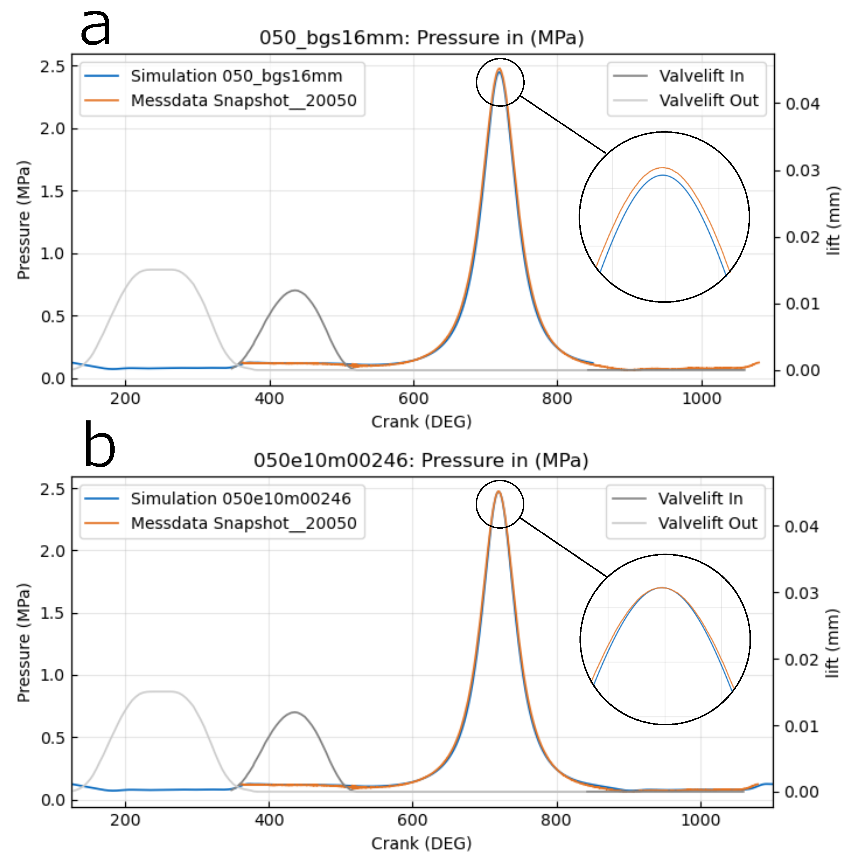
In conclusion, it can be said that some optical engines have a non-neglectable blow-by, and this has to be accounted for in the modeling. For the engine of the Institute of Sustainable Mobile Powertrains the blow-by is assumed to be near zero because of the different sealing concept. We use non-sliced piston rings made of PTFE. They need special equipment for mounting and have to be changed after approximately 3 hours of engine operation. This is a huge amount of maintenance but is rewarded with a very well-sealed combustion chamber and well-fitting pressure curves, as seen in
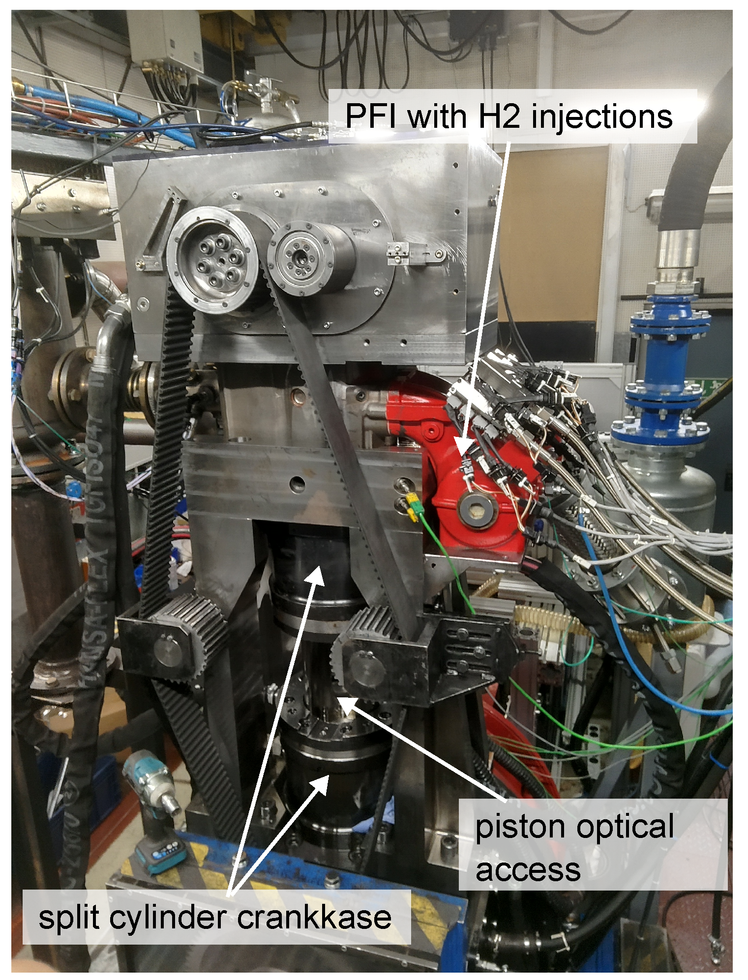
Figure 3. In this state of the simulation, we applied a correction of the intake pressure curve of +0.0246 MPa. This is necessary because the inflow boundary is not yet located at the plane of the pressure sensor, which is located at the entry of the plenum (see red PFI in
Figure 2). For the last delta in maximum pressure, we suggest a compression ratio fitting (variation of epsilon) to account for the elastic piston deformation.
3.3. Heat Losses of Optical Engines
Especially when it comes to hydrogen combustion, the heat distribution in the combustion area is crucial. This is especially important for gaining insights into controlling frequently occurring combustion anomalies like pre-ignition, knock, lube oil ignition, and backfire. In optical engines, the piston materials strongly differ from those of thermodynamic engines. Also, the cooling system is not the same due to adaptions needed for optical access. Knowing about those differences is fundamental to investigating hydrogen combustion and its irregularities. A detailed investigation was made by [
8]. They compared five different engine concepts and their heat transfer characteristics. This included an optical engine in Bowditch-design, as used at NMA but in much smaller scale. The engine of [
8] has two different piston crevices and a metal piston instead of glass ones. The heat transfer and heat release for those experiments were calculated after [
23]. Their findings were described as follows:
duration of combustion elongates with an enhancement of optical access;
delay of combustion process is dependent on heat losses of cylindric wall and is shortest with a piston made of quartz;
optical engines are quite independent at the start of injection SOI.
A different approach was taken by [
2] at NMA for the fully-accessible large-bore optical engine. In an experimental approach [
2] describes the heat losses in this optical engine coming from the piston’s fire land as major. [
2] shows in calculations that at a compression ratio of 17, about 10% of the gas fraction is in all crevice volumes of the engine. When one considers the colder wall temperatures and follows the colder gas temperature in those crevice volumes, it comes up to 20% of the gaseous mass fraction within those crevices. The gap between the expected and observed pressure maximum in the experiment was measured. The peak pressure occurred earlier at the optical engine than at standard thermodynamic ones with smaller gap volumes. [
9] describes the same effects. His clearance volume is more prominent because of lower-placed piston rings and an in-cylinder pressure sensor instead of a spark plug. The wall heat losses are described as minor due to the use of optical materials. But it follows no quantification and closer specification of those phenomena. [
10] addresses the larger gap volumes through a special simulation approach. His Large Eddy Simulation (LES) shows that combustion reaches inside the piston crevice but doesn’t burn the fuel completely there. In LES, the Navier Stokes Equations are filtered, and large eddies are directly calculated. This reduces the modeling affords compared to Reynolds Averaged Navier Stokes Equations (RANS) [
24]. Due to the incomplete combustion in piston fire land, fuel slip, heat transfer, and cylinder pressure are affected. In conclusion, those losses in crevices should always be accounted for in optical engine simulation.
3.4. Special Heat Transfer Phenomena of Hydrogen
Additionally to the engine geometry, the strongly different characteristics of hydrogen have to be considered to describe the heat transfer mechanisms sufficiently. The best way is to use the heat flux coefficient of the media. [
14] and [
15] proposed well proven methods. [
11,
12] measured the heat flux coefficient of hydrogen and determined a value larger than the one described by [
14] previously. Hydrogen combustion is often compared to methane combustion, but the heat transport capability is larger than that of methane due to its smaller quenching distance [
13] as shown in
Table 2 . For stoichiometric or near stoichiometric mixtures, the flame speeds are very high, which leads to fast density changes and results in higher convection. With respect to the thermal properties of hydrogen, the resulting thermal conductivity of the mixture is much higher compared to hydrocarbon mixtures (see
Table 2). [
12] proposes an alternative equation for heat transport that agrees well with its own measurements. It depends on the time of ignition and fuel-air-ratio and gives the rate of heat release as a result. [
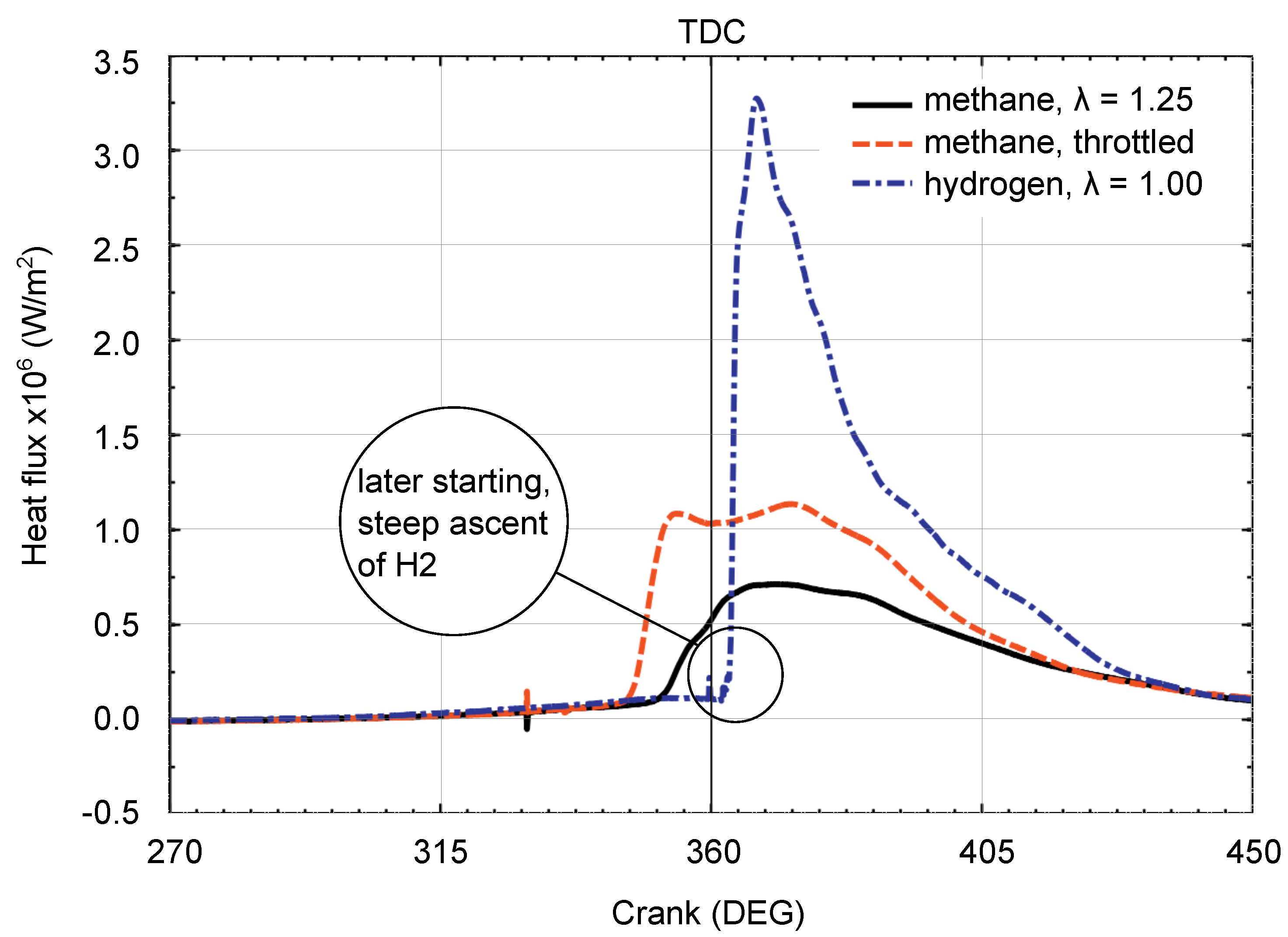
25] shows those described effects in a graph of the local heat flux
Figure 4. Hydrogen shows the steepest increase in heat flux compared to the one measured by methane. They also show that the maximum gas and wall temperatures are higher at hydrogen combustion. With the steep increase of heat flux comes the observation that the time between ignition and heat flux maximum is very short at hydrogen combustion. Following those findings, not only does the engine design affect the combustion mode, but one should also avoid the simplification of using methane instead of hydrogen combustion mechanisms.
3.5. Consequences and Design Optimizations for Hydrogen Combustion
One promising step towards design optimization of hydrogen combustion was made by [
16,
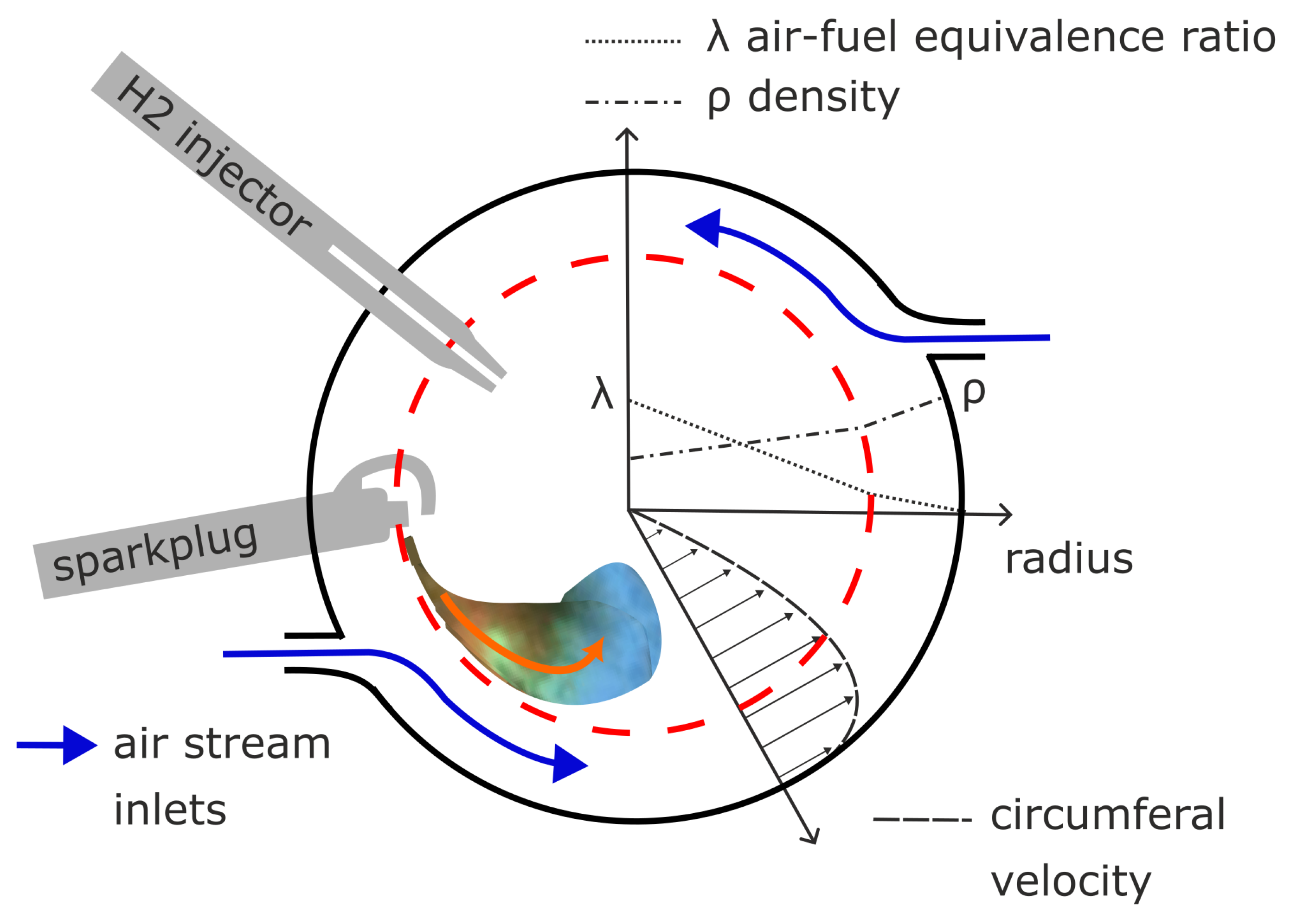
17] in an optical engine with a large pre-chamber. They reduce the heat flux by about 50% by forming eddies to separate fresh air from the fuel-air mixture in the center of the combustion area. This happens by using the Coandă Effect [
28] in the large cylindric pre-chamber, where two separate areas of flow are created by two tangentially oriented inflows. In the outer wall-near area, the flow of pure air is rotating, and in the more central area is the lighter fuel-air mixture, as seen in
Figure 5. The flow accelerates with the compression stroke proceeding so that the directly injected fuel and air are rapidly mixed. Due to gravity effects and the centripetal forces, the lighter hydrogen and its combustion products with lower density move further inward. The differences in density between the outer and inner areas get higher with the proceeding heat release of the hydrogen combustion. In the borderline case of the rotating fuel speed being too high, this leads to too early extinction of the flame in the central area. Then the air-fuel equivalence ratio (
) is too low in this central area. The results shown in the experiments and the CFD simulations of [
17] are promising, but for a practical engine concept, some major changes are needed in the pre-chamber design. Because in a more practical setup, the heat losses of the hot gas passing from the pre-chamber to the engine cylinder to do the mechanical work there are too significant. The conclusions we draw from this for combustion development at NMA is to focus on those centripetal speeds in our engine cylinder. The question is how we may create similar benefits by using swirl and tumble effects in our large-bore engine.
3.6. Conclusion Thermal Losses on Hydrogen Combustion
Thermal losses through the cylindric walls seem to be of no significant interest at conventional fuels. But when it comes to hydrogen combustion, this is changing. Hydrogen burns closer to the cylindric walls and has a higher heat flux coefficient with its high combustion temperature. In optical engines, thermal losses are minor compared to standard thermodynamic engines, and due to the enlarged crevice volume, the amount of unburnt fuel increases. These circumstances have to be taken into consideration when it comes to designing hydrogen combustion processes.
4. Discussion
All those different findings and approaches show that there isn’t one solution for all optical engines. Furthermore, one has to consider carefully which modeling is appropriate and necessary for the addressed problem. For blow-by, it’s obvious, that the general statement "it’s widely known that optical engines suffer from large blow-by compared to thermodynamic engines" isn’t true for every optical engine. At NMA, we consider the modeling of blow-by not necessary in our CFD simulations due to the tight sealing concept developed at NMA, especially for those full-scale large-bore optical engines [
18]. The PTFE sealings, usually used in air compressors, work very well in this environment. However, due to their reduced thermal resistance, the maintenance is high for the optical test site (change of sealings every three hours of test site operation time). Important knowledge for the simulation about the quality of the engine’s sealing can be gained by properly validating the cold flow simulation. If the peak pressure and the pressure curve of the in-cylinder pressure in measurement and simulation are well-fitting, like shown in
Figure 3, this is a good sign for the following combustion simulation. Despite neglecting the effects of blow-by, the thermodynamic losses of NMA’s optical engine due to increased gap volumes have to be considered. This happens in accurate modeling and meshing of those gap volumes, namely the elongated piston crevice and the gap around the lateral optical access. Another point that was considered in the simulation was the structural integrity of the elongated crank itself. The whole piston and crank construction is much more elastic than the ones of standard thermodynamic engines. To this point, we can say that this effect is not as significant as the thermodynamic influence of the gap volumes. Then there are further thermodynamic differences that have to be considered as well. On the one hand, there are different engine materials that might influence combustion and, therefore, have to be adequately modeled in the CFD simulation. On the other hand there is the differing behaviour of the fuel hydrogen itself. Because hydrogen burns close to the walls, it might be crucial to model the heat characteristics near the cylinder wall. Especially when it comes to combustion anomalies, hot spots at the cylindric liner or the exhaust valves have to be taken a closer look at. The aim is to understand the combustion process completely, so that those hot locations can be avoided, and following hydrogen combustion can be controlled and anomalies prevented. The result will be highly efficient, GHG-neutral hydrogen combustion engines, reliable and long-range, that bring marine applications to their goal of carbon-free transport at around or before 2050, at least.
(2050 is the IMO’s goal for carbon-free marine transport [
29]).
Author Contributions
Conceptualization, methodology, validation, E. Flesch; writing, original—draft preparation, E. Flesch, E. Glocker; writing—review and editing, E. Flesch; visualization, E. Flesch, E. Glocker; supervision, M. Jaensch, M. Prager; project administration, M. Prager; funding acquisition, M. Prager. All authors have read and agreed to the published version of the manuscript.
Funding
The investigations on optical engines, CFD-simulations, and for approaching new hydrogen combustion concepts were part of the HydroPoLEn project, funded by the German Federal Ministry for Economic Affairs and Climate Action based on a decision by the German Bundestag (project no. 03SX570B), which is gratefully acknowledged.
Acknowledgments
The authors like to thank for the prosperous cooperation within the HydroPoLEn project, especially in CFD exchange with our partners MAN Energy Solutions SE and Tenneco. The authors also want to acknowledge CONVERGE CFD for providing the software, licenses, and technical support for conducting the simulations. Many inspiring discussions at the chair of sustainable mobile powertrains led to this work and are gratefully acknowledged, with special thanks to Andreas Zepf.
Abbreviations
The following abbreviations are used in this manuscript:
| CH4 |
Methane |
| CFD |
Computational Fluid Dynamics |
| DOAJ |
Directory of open access journals |
| GHG |
Greenhouse gas |
| H2 |
Hydrogen |
| IMO |
International Maritime Organization |
| LD |
Linear Dichroism |
| LES |
Large Eddy Simulation |
| MDPI |
Multidisciplinary Digital Publishing Institute |
| NMA |
Institute of Sustainable Mobile Powertraings, TUM |
| PTFE |
Polytetrafluoroethylene |
| RANS |
Reynolds-Averaged Navier–Stokes Equations |
| STP |
Standard Temperature and Pressure |
| TLA |
Three letter acronym |
|
Air-fuel equivalence ratio |
References
- de Renzis, E.; Mariani, V.; Bianchi, G.M.; Cazzoli, G.; Falfari, S.; Antetomaso, C.; Irimescu, A. Implementation of a Multi-Zone Numerical Blow-by Model and Its Integration with CFD Simulations for Estimating Collateral Mass and Heat Fluxes in Optical Engines. Energies 2021, 14, 8566. doi:10.3390/en14248566. [CrossRef]
- Gleis, S. Optische Untersuchung eines diffusiven Dual-Fuel Brennverfahrens für Erdgas sowie alternative Kraftstoffe mit niedriger Zündwilligkeit. Dissertation, Technische Universität München, München, 2023.
- Eicheldinger, S.; Waligorski, D.; Wachtmeister, G.; Jaensch, M. Leistungspotenzial von Wasserstoffverbrennungsmotoren für Industrieanwendungen. MTZ - Motortechnische Zeitschrift 2022, 83, 58–62. doi:10.1007/s35146-022-0859-x. [CrossRef]
- Eicheldinger, S.; Karmann, S.; Prager, M.; Wachtmeister, G. Optical screening investigations of backfire in a large bore medium speed hydrogen engine. International Journal of Engine Research 2022, 23, 893–906. doi:10.1177/14680874211053171. [CrossRef]
- Zhao, J.X.; Lee, C.f.F. Modeling of Blow-by in a Small-Bore High-Speed Direct-Injection Optically Accessible Diesel Engine. SAE 2006 World Congress & Exhibition. SAE International, 2006. doi:10.4271/2006-01-0649. [CrossRef]
- Namazian, M.; Heywood, J.B. Flow in the Piston-Cylinder-Ring Crevices of a Spark-Ignition Engine: Effect on Hydrocarbon Emissions, Efficiency and Power. SAE Transactions 1982, 91, 261–288.
- Kashdan, J.; Thirouard, B. Optical Engines as Representative Tools in the Development of New Combustion Engine Concepts. Oil & Gas Science and Technology – Revue d’IFP Energies nouvelles 2011, 66, 759–777. doi:10.2516/ogst/2011134. [CrossRef]
- Aronsson, U.; Chartier, C.; Horn, U.; Andersson, Ö.; Johansson, B.; Egnell, R. Heat Release Comparison Between Optical and All-Metal HSDI Diesel Engines. SAE Technical Paper Series. SAE International400 Commonwealth Drive, Warrendale, PA, United States, 2008, SAE Technical Paper Series. doi:10.4271/2008-01-1062. [CrossRef]
- Ohrnberger, T.D. Einspritzdüsenauslegungen und Brennraum- geometrien für ein direkteinspritzendes 2-Ventil-Dieselbrennverfahren. PhD thesis, Technische Universität München, München, 2010.
- Janas, P.; Ribeiro, M.D.; Kempf, A.; Schild, M.; Kaiser, S.A. Penetration of the Flame Into the Top-Land Crevice - Large-Eddy Simulation and Experimental High-Speed Visualization. SAE Technical Paper Series. SAE International400 Commonwealth Drive, Warrendale, PA, United States, 2015, SAE Technical Paper Series. doi:10.4271/2015-01-1907. [CrossRef]
- Shudo, T.; Nabetani, S. Analysis of Degree of Constant Volume and Cooling Loss in a Hydrogen Fuelled SI Engine. SAE Technical Paper Series. SAE International400 Commonwealth Drive, Warrendale, PA, United States, 2001, SAE Technical Paper Series. doi:10.4271/2001-01-3561. [CrossRef]
- Shudo, T.; Suzuki, H. New Heat Transfer Equation Applicable to Hydrogen-Fuelled Engines. Design, Application, Performance and Emissions of Modern Internal Combustion Engine Systems and Components. ASMEDC, 09082002, pp. 335–341. doi:10.1115/ICEF2002-515. [CrossRef]
- Verhelst, S.; Wallner, T. Hydrogen-fueled internal combustion engines. Progress in Energy and Combustion Science 2009, 35, 490–527. doi:10.1016/j.pecs.2009.08.001. [CrossRef]
- Woschni, G. A Universally Applicable Equation for the Instantaneous Heat Transfer Coefficient in the Internal Combustion Engine. SAE Technical Paper Series. SAE International400 Commonwealth Drive, Warrendale, PA, United States, 1967, SAE Technical Paper Series. doi:10.4271/670931. [CrossRef]
- Annand, W.J.D. Heat Transfer in the Cylinders of Reciprocating Internal Combustion Engines. Proceedings of the Institution of Mechanical Engineers 1963, 177, 973–996. doi:10.1243/PIME_PROC_1963_177_069_02. [CrossRef]
- Oh, D.; Brouillette, M.; Plante, J.S. Reduced Convective Combustion Chamber Wall Heat Transfer Losses of Hydrogen-Fueled Engines by Vortex-Stratified Combustion - Part 2: Numerical Analyses. SAE International Journal of Engines 2017, 10, 2259–2274. doi:10.4271/2017-01-9287. [CrossRef]
- Oh, D.; Brouillette, M.; Plante, J.S. Reduced Convective Combustion Chamber Wall Heat Transfer Losses of Hydrogen-Fueled Engines by Vortex-Stratified Combustion - Part 1: Background and Optical Engine Observations. SAE International Journal of Engines 2017, 10, 2248–2258.
- Stephan Gleis.; Stephanie Frankl.; Dominik Waligorski.; Dr.-Ing. Maximilian Prager.; Prof. Dr.-Ing. Georg Wachtmeister. Investigation of the High-Pressure-Dual-Fuel (HPDF) combustion process of natural gas on a fully optically accessible research engine. SAE Technical Paper 2019-01-2172 2019, 2019. doi:10.4271/2019-01-2172. [CrossRef]
- Stephan Bernhard Karmann. Entwicklung eines kompakten volloptischen Zugangs für Großmotoren und Anwendung für die Verbrennungsdiagnostik erneuerbarer Kraftstoffe. PhD thesis, Technische Universität München, München, 2023.
- Irimescu, A.; Tornatore, C.; Marchitto, L.; Merola, S.S. Compression ratio and blow-by rates estimation based on motored pressure trace analysis for an optical spark ignition engine. Applied Thermal Engineering 2013, 61, 101–109. doi:10.1016/j.applthermaleng.2013.07.036. [CrossRef]
- Irimescu, A.; Merola, S.S.; Tornatore, C.; Valentino, G. Development of a semi-empirical convective heat transfer correlation based on thermodynamic and optical measurements in a spark ignition engine. Applied Energy 2015, 157, 777–788. doi:10.1016/j.apenergy.2015.02.050. [CrossRef]
- Pastor, J.; Olmeda, P.; Martín, J.; Lewiski, F. Methodology for Optical Engine Characterization by Means of the Combination of Experimental and Modeling Techniques. Applied Sciences 2018, 8, 2571. doi:10.3390/app8122571. [CrossRef]
- Heywood, J.B. Internal Combustion Engine Fundamentals, 2nd edition ed.; McGraw-Hill Education: New York, 2018.
- Fröhlich, J. Large Eddy Simulation turbulenter Strömungen: mit 14 Tabellen, 1. ed.; Teubner: Wiesbaden, 2006. doi:10.1007/978-3-8351-9051-1. [CrossRef]
- Demuynck, J.; Raes, N.; Zuliani, M.; de Paepe, M.; Sierens, R.; Verhelst, S. Local heat flux measurements in a hydrogen and methane spark ignition engine with a thermopile sensor. International Journal of Hydrogen Energy 2009, 34, 9857–9868. doi:10.1016/j.ijhydene.2009.10.035. [CrossRef]
- Armbruster, F.; Kraus, C.; Prager, M.; Härtl, M.; Jaensch, M. Optimized Emission Analysis in Hydrogen Internal Combustion Engines: Fourier Transform Infrared Spectroscopy Innovations and Exhaust Humidity Analysis. SAE International Journal of Engines 2024, 17. doi:10.4271/03-17-07-0052. [CrossRef]
- van Basshuysen, R.; Schäfer, F. Handbuch Verbrennungsmotor; Springer Fachmedien Wiesbaden: Wiesbaden, 2017. doi:10.1007/978-3-658-10902-8. [CrossRef]
- Dumitrache, A.; Frunzulica, F.; Ionescu, T.C. Mathematical Modelling and Numerical Investigations on the Coanda Effect. In Nonlinearity, Bifurcation and Chaos; Awrejcewicz, J.; Hagedorn, P., Eds.; IntechOpen: Erscheinungsort nicht ermittelbar, 2012. doi:10.5772/50403. [CrossRef]
- IMO. 2023 IMO Strategy on Reduction of GHG Emissions from Ships: RESOLUTION MEPC.377(80).
|
Disclaimer/Publisher’s Note: The statements, opinions and data contained in all publications are solely those of the individual author(s) and contributor(s) and not of MDPI and/or the editor(s). MDPI and/or the editor(s) disclaim responsibility for any injury to people or property resulting from any ideas, methods, instructions or products referred to in the content. |
© 2024 by the authors. Licensee MDPI, Basel, Switzerland. This article is an open access article distributed under the terms and conditions of the Creative Commons Attribution (CC BY) license (http://creativecommons.org/licenses/by/4.0/).
