Introduction
Variable Reluctance Resolvers (VRRs) have emerged as critical components in precision control systems, particularly in advanced fields such as electric vehicles (EVs) and aerospace applications [
1,
2,
3,
4,
5,
6,
7,
8,
9,
10,
11,
12,
13,
14]. With the increasing demand for high-efficiency and high-precision motor control, VRRs have become indispensable for detecting angular positions and enhancing system performance in harsh environments [
15,
16,
17,
18,
19]. Their robustness and reliability in providing absolute position information make them essential for the accurate control of Permanent Magnet Synchronous Motors (PMSMs) and other electric drive systems in electric and hybrid vehicles [
6,
20].
Despite their advantages, conventional VRR designs face several limitations. One of the primary issues lies in the asymmetry of the stator winding structure, which results in non-orthogonal signal output and contributes to harmonic distortions [
4,
6,
7,
12,
14,
15,
16,
17,
18,
21,
22,
23]. Inductance harmonics caused by imperfections in the resolver’s construction can lead to significant position errors [
18,
19]. Additionally, fluctuations in slot leakage flux further degrade the accuracy of the resolver, negatively affecting motor control precision [
3,
4,
5,
6,
8,
11,
24,
25]. Mechanical imperfections such as rotor eccentricity and uneven magnetic fields can also introduce significant position errors [
2,
3,
7,
8,
10,
20,
23,
26]. These challenges are exacerbated by manufacturing inaccuracies and mechanical misalignments, leading to position errors that are detrimental in high-performance applications. Consequently, there is a pressing need for innovative solutions that can address both structural and electromagnetic inefficiencies in conventional VRRs.
Previous studies have attempted to address these challenges through various approaches. Structural modifications, such as optimizing rotor contour design to inject auxiliary air-gap permeance harmonics, have been proposed to reduce harmonic distortions and improve detection accuracy [
27]. The adoption of non-overlapping tooth-coil windings with uniform coils has been suggested to simplify manufacturing and reduce winding asymmetry [
1,
16]. Rotor pole shape optimization using genetic algorithms has also been explored to minimize harmonics in the air-gap permeance [
15,
28].
Advanced electromagnetic modeling techniques have been employed to analyze and predict the behavior of VRRs under various conditions. Finite Element Analysis (FEA) simulations have been widely used to validate design improvements and analyze the effects of eccentricity, short circuits, and material defects on resolver performance [
2,
3,
4,
5,
19,
22,
26,
29]. Analytical models have been developed to calculate air-gap inductance and leakage fluxes more accurately, enhancing the understanding of electromagnetic interactions within the resolver [
24,
25,
29]. Precise modeling of air-gap and zigzag leakage fluxes in permanent magnet machines has been shown to significantly improve torque predictions and machine optimization [
24,
25]. While these methods have shown promise, they often rely heavily on computationally intensive simulations and may not fully address the complexities of stator design flaws.
Signal processing techniques have also been proposed to minimize position errors caused by non-ideal resolver signals, including errors due to amplitude imbalance, imperfect quadrature, and inductance harmonics [
17,
18]. These methods address issues such as amplitude imbalance and quadrature errors, which can introduce significant position errors if not properly managed. However, while effective, these approaches often involve complex design adjustments or elaborate calibration processes, which can be impractical for widespread industrial adoption.
The advent of artificial intelligence (AI) and machine learning (ML) techniques offers new avenues for optimizing electromagnetic devices [
30,
31,
32,
33]. AI techniques have been integrated with computational electromagnetics to enhance the efficiency, accuracy, and speed of electromagnetic simulations, focusing on applications like electrical machine design, topology optimization, and fault diagnosis [
30]. Machine learning models, such as neural networks and support vector machines, have been used to model electromagnetic fields, predict system performance, and optimize designs with less computational effort compared to conventional methods [
30,
34,
35].
In the context of electric machines, ML techniques have been applied to optimize parameters and improve performance. For example, neural networks have been used for model order reduction in PMSMs, enabling accurate and computationally efficient surrogate models [
31]. ML-based optimization methods have been employed to enhance the design of PMSMs, achieving better performance with reduced computational costs [
32,
33,
36,
37]. Hybrid approaches combining machine learning algorithms with optimization algorithms like genetic algorithms and NSGA-II have shown significant improvements in motor design efficiency and performance [
36,
37]. However, the application of advanced ML techniques such as Extreme Gradient Boosting (XGBoost) and Multi-Layer Perceptron (MLP) to VRR optimization remains relatively unexplored.
Recently, machine learning techniques have shown promise in addressing complex nonlinearities in electromagnetic systems. Hybrid machine learning models, such as those combining Random Forest Regressor with K-Nearest Neighbors or Support Vector Machines, have been effective in predicting and optimizing performance parameters in electrical machines [
38,
39]. Reinforcement learning and neural network architectures have been applied to minimize torque ripples in variable reluctance motors, improving control precision [
40,
41]. Furthermore, fuzzy-based multiple instance learning has been employed for transparent and accurate classification in biomedical signal processing, demonstrating the versatility of machine learning approaches [
42].
These advancements underscore the potential of integrating machine learning techniques into VRR design optimization. By leveraging machine learning models to analyze and predict electromagnetic parameters, it is possible to systematically reduce harmonic distortions and flux leakage caused by design flaws. Moreover, integrating ML with model-based approaches has shown promise in other areas of electric machine design and fault diagnosis, suggesting potential benefits for VRR optimization [
43,
44].
To overcome the challenges associated with conventional VRR designs, this study aims to optimize the stator structure of the VRR by leveraging advanced machine learning techniques, namely XGBoost and Multi-Layer Perceptron (MLP). By analyzing and predicting electromagnetic parameters using these models, we seek to reduce the harmonic distortions and flux leakage caused by stator design imperfections. This approach enables us to systematically improve the accuracy of the resolver without necessitating complex structural modifications or extensive calibration, leading to more precise motor control in applications such as electric vehicles and robotics.
1. Model Design and Methods
This study focuses on enhancing the accuracy of a Segmented Sinusoidal Parameter Winding with Magnetic Wedge (SSPWMW) Variable Reluctance Resolver (VRR) by simulating and optimizing its stator structure. The key components under analysis include the segmented sinusoidal windings, magnetic slot wedges, and the rotor-stator configuration. Through a combination of Particle Swarm Optimization (PSO) for winding design, Magnetic Equivalent Circuit (MEC) analysis for slot leakage flux, and machine learning for stator slot shape optimization, aim to improve resolver accuracy by addressing both structural and electromagnetic inefficiencies.
1.1. SSPWMW-VRR Structure and Components
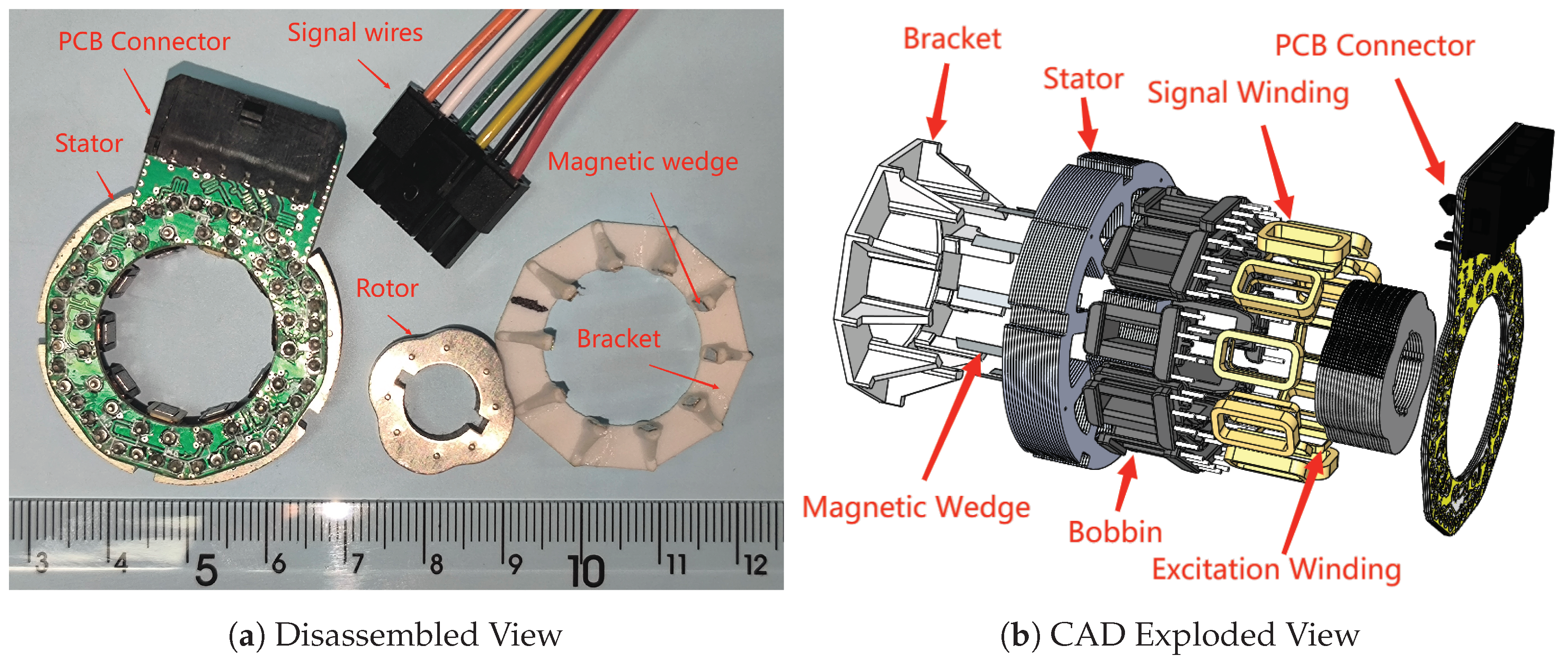
The Segmented Sinusoidal Parameter Winding with Magnetic Wedge (SSPWMW-VRR) is designed to minimize harmonic distortion and improve signal integrity through a specialized winding configuration. As shown in
Figure 1, the prototype consists of key components including the stator, a printed circuit board (PCB) connection board, a salient pole rotor, and a magnetic slot wedge with its supporting structure.
A crucial feature of the SSPWMW-VRR design is the use of a PCB connection to create a more uniform and reliable electrical connection between the stator windings. This method streamlines the manufacturing process and enhances the spatial symmetry of the two-phase windings. By enabling interleaved winding phases, the design significantly improves winding symmetry and orthogonality, which are essential for accurate signal generation.
Another important component is the magnetic slot wedge, which plays a vital role in directing the magnetic field within the stator slots. Comprising a thin magnetic strip fixed to a supporting structure, it is strategically positioned to enhance the magnetic interaction between the rotor and stator. The presence of the magnetic slot wedge effectively diminishes the air gap between these components, leading to improved signal quality and reduced position error.
1.2. Optimization of Winding Turns Using Particle Swarm Optimization
In the design of the resolver, the sine and cosine windings should ideally follow a continuous sinusoidal distribution to achieve perfect orthogonality and minimize harmonic distortion. However, in practical implementations, the number of turns in each slot must be an integer, necessitating the rounding of the continuous winding functions into discrete values. This rounding process introduces challenges in maintaining the orthogonality and symmetry of the windings, both of which are crucial for accurate signal generation.
To ensure that the rounding process maintains these critical properties, the following conditions must be met:
The inner product between the sine and cosine windings must be zero to ensure orthogonality.
The sum of the winding turns over a complete cycle must be zero for both windings to preserve symmetry.
The number of positive and negative turns must be balanced to maintain the symmetry of the induced signal.
Achieving these conditions becomes particularly challenging in resolver design due to the discrete nature of winding turns and the limited number of slots available on the stator. These constraints reduce the flexibility in distributing winding turns evenly, making it difficult to achieve perfect orthogonality and symmetry. To address this, the continuous winding functions are scaled by a winding distribution coefficient, , which adjusts the amplitude before rounding. Finding suitable values of that satisfy the above conditions after rounding requires a robust global search algorithm.
Particle Swarm Optimization (PSO) is employed to tackle this optimization challenge. As an evolutionary computation technique inspired by the collective behavior of bird flocking and fish schooling, PSO excels at solving complex, multidimensional problems. In this context, PSO is used to systematically explore the parameter space, searching for values of that satisfy the orthogonality and symmetry requirements after rounding.
The optimization objective is formally defined to ensure that the rounded winding turns meet the following conditions:
where
and
represent the rounded integer turns for the sine and cosine windings at slot
j, respectively. The inner product
ensures orthogonality, while the sums
and
enforce symmetry.
Through iterative exploration, the PSO algorithm efficiently identifies optimal values of , ensuring that the discrete winding turns maintain orthogonality and symmetry across various pole pairs and slot configurations. This minimizes harmonic distortion and enhances resolver accuracy.As the first optimization step, PSO provides a robust winding configuration, forming the basis for subsequent analyses, such as Magnetic Equivalent Circuit (MEC) modeling and machine learning-driven stator shape optimization.By optimizing the winding design using PSO, the resolver achieves reduced harmonic distortion and improved signal quality, contributing to higher overall accuracy.
1.3. Analysis of Slot Leakage Flux Using Magnetic Equivalent Circuit
To accurately analyze the impact of slot leakage flux on the resolver’s performance, the Magnetic Equivalent Circuit (MEC) method is employed. MEC provides a detailed representation of the magnetic flux distribution, allowing for precise simulation of magnetic behavior within the stator slots. The key factor contributing to accuracy degradation in the resolver is the periodic fluctuation of slot leakage inductance as the rotor rotates, which distorts the magnetic field and negatively affects signal accuracy.
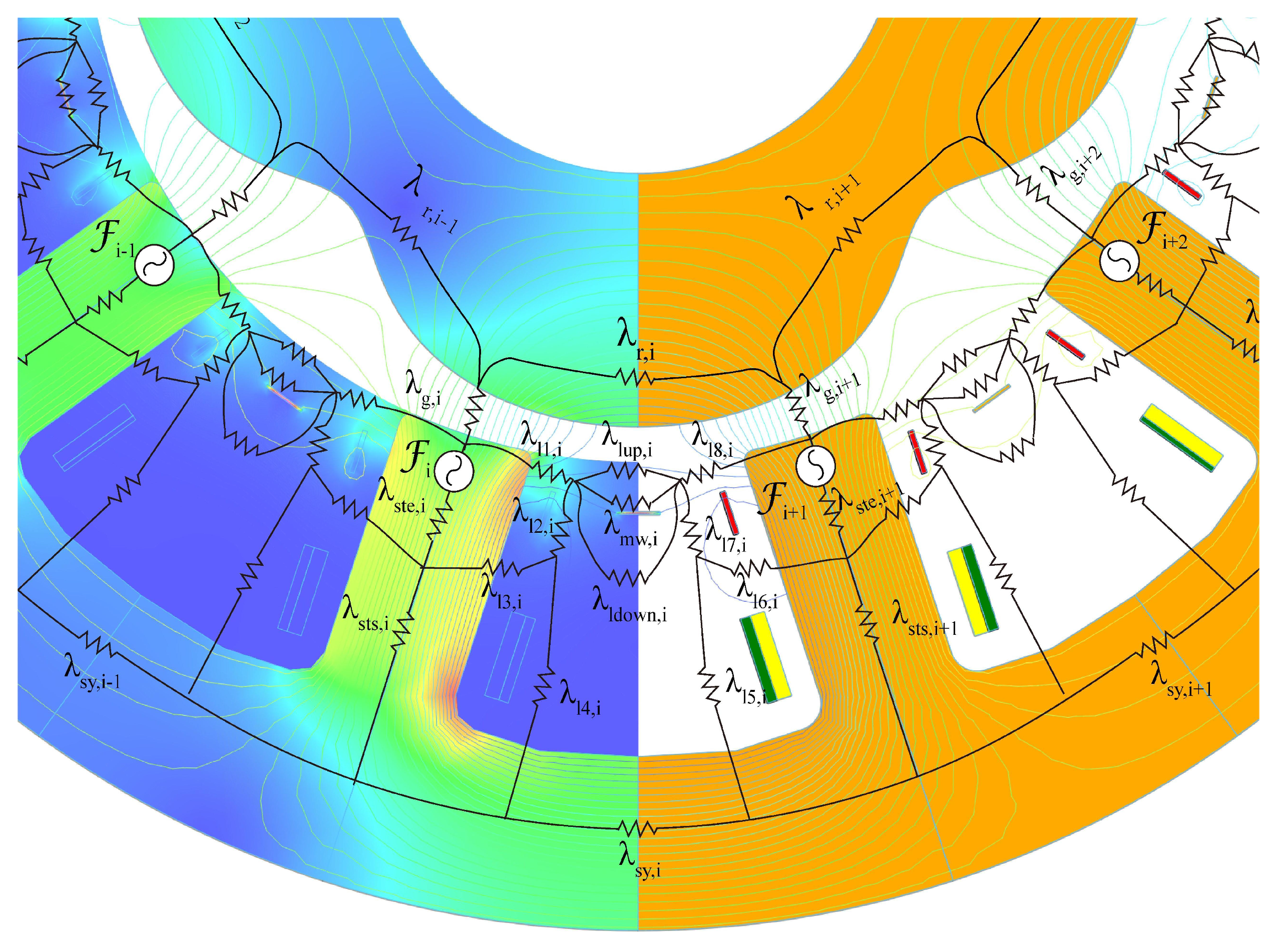
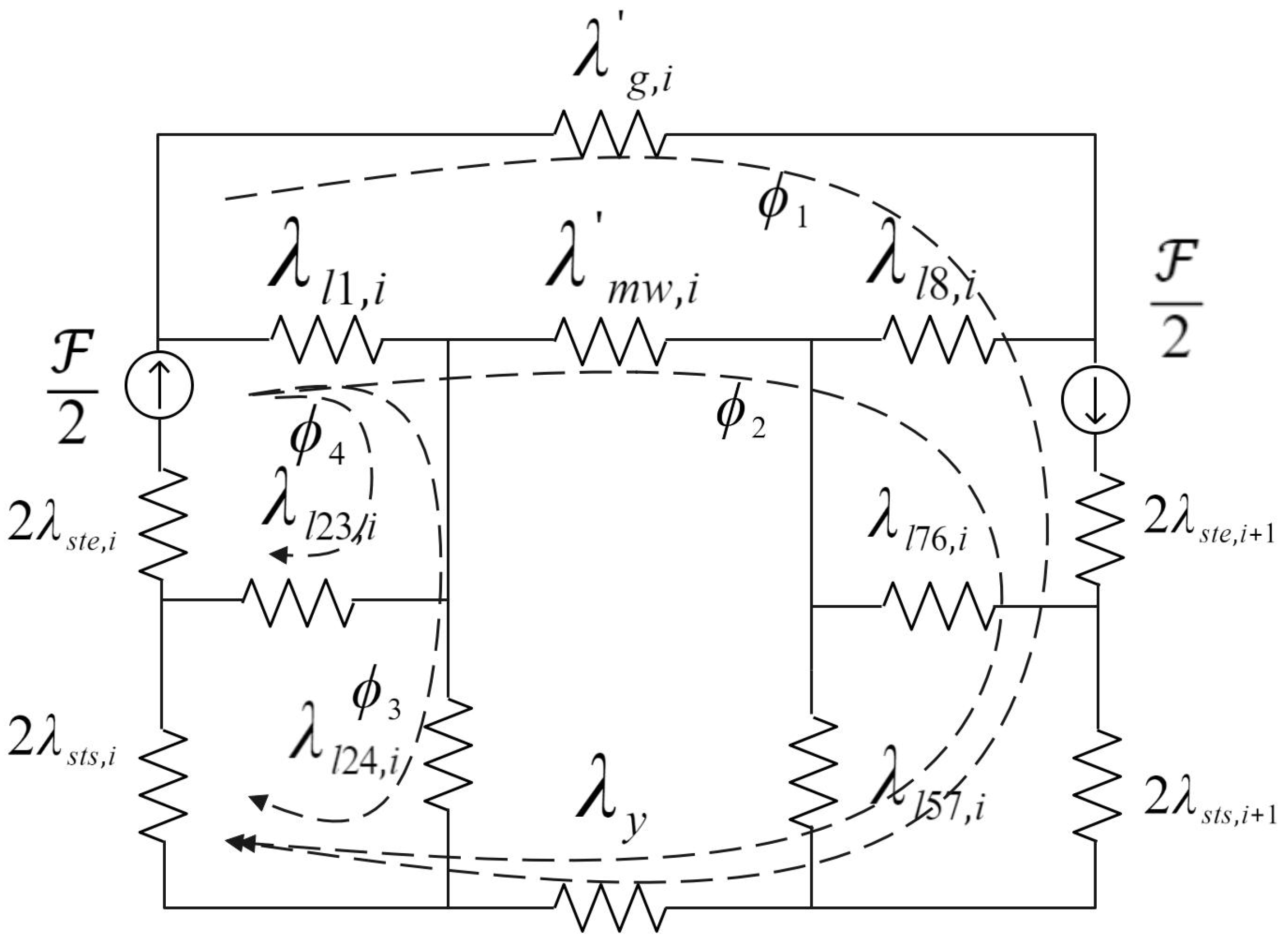
The MEC model, depicted in
Figure 2, is constructed based on the SSPWMW-VRR stator design, including the segmented sinusoidal windings and magnetic slot wedges. By applying Ohm’s law to the magnetic circuit, the model divides the magnetic path into the main magnetic circuit and three leakage magnetic circuits: (1) leakage between adjacent stator teeth, (2) leakage between excitation and signal windings, and (3) leakage from the tooth top to the stator yoke.
The role of the magnetic slot wedge is critical in regulating the distribution of slot leakage flux. By adjusting the wedge’s thickness and its positioning relative to the slot, the leakage flux can be controlled to minimize distortion in the resolver’s magnetic field. This fine-tuning reduces the variability of the slot leakage inductance, helping to stabilize the resolver’s output signal.
MEC analysis offers several advantages:
Accurate Simulation: It provides a precise simulation of the magnetic behavior, capturing complex interactions between the stator, rotor, and magnetic slot wedge.
Key Input for Machine Learning: The insights gained from MEC analysis, including flux densities and inductance variations, serve as critical features for machine learning models that will be used in later stages to optimize the stator slot design.
Complementary to PSO: The optimized winding configuration obtained from PSO is further refined through MEC, which identifies how the magnetic circuit behaves with these optimized windings. This sequential approach ensures that both winding and magnetic circuit optimizations are aligned.
By modeling the intricate magnetic properties using MEC, this analysis plays a crucial role in the integrated optimization framework. It not only enhances the accuracy of the resolver by mitigating the adverse effects of slot leakage flux but also serves as a foundational step in generating high-quality data for machine learning-driven stator slot shape optimization. Thus, MEC analysis bridges the gap between winding optimization and machine learning, ensuring that the entire system is fine-tuned for optimal resolver performance.
1.4. Stator Slot Shape Optimization Using Machine Learning
The final step in optimizing the SSPWMW-VRR involves the use of machine learning models to fine-tune the stator slot shape based on the results obtained from previous stages, including the Particle Swarm Optimization (PSO) for winding design and the Magnetic Equivalent Circuit (MEC) analysis of slot leakage flux. Machine learning enables more precise predictions and optimizations, minimizing the need for exhaustive physical simulations.
By employing advanced models such as XGBoost and Multi-Layer Perceptron (MLP), the optimization framework utilizes data from both finite element analysis (FEA) and MEC simulations. These models are trained on datasets constructed from key electromagnetic features, including flux density, inductance variations, and other critical parameters. This allows the models to predict how different stator slot configurations impact the resolver’s accuracy, performance, and overall signal quality.
1.4.1. Simulation System Framework
The machine learning-driven optimization process is structured into three distinct layers (as illustrated in
Figure 3:
Inner Layer (Simulation Layer): This layer is powered by CST Studio Suite and Opera FEA software, where detailed electromagnetic simulations of the VRR are performed. These simulations provide foundational data regarding key parameters such as magnetic flux density distribution, field lines, and other electromagnetic characteristics, which serve as critical inputs for the machine learning models. The data collected at this stage is crucial for the training and validation of machine learning algorithms.
Middle Layer (Data Processing and Feature Extraction): In this layer, data generated from FEA and MEC simulations are processed and decoded using Python scripts. This step is responsible for extracting relevant electromagnetic features, such as flux density values and slot leakage flux behavior, which are then transformed into a format suitable for machine learning models. The processed data is essential for creating the input features and target variables for the predictive models.
Outer Layer (Machine Learning and Optimization): This layer is where machine learning models, specifically XGBoost and MLP, are trained on the data extracted from the previous layers. The models are used to predict the impact of various stator slot shapes on resolver accuracy, allowing for rapid evaluation and optimization of slot parameters. Machine learning provides insights into the optimal slot configurations, enhancing resolver performance without requiring extensive trial-and-error physical tests.
1.4.2. Machine Learning Models: XGBoost and Multi-Layer Perceptron (MLP)
Two machine learning models, XGBoost and Multi-Layer Perceptron (MLP), are employed to optimize the stator slot shape. These models are designed to capture complex relationships between slot parameters and resolver performance. The optimization process is described as follows:
Data Preparation: Electromagnetic data from FEA and MEC simulations are compiled into a comprehensive dataset. This dataset includes key features such as stator slot width, jaw width, and slot wedge thickness, as well as target variables like magnetic flux densities, torque ripple values, and induced voltage errors. The dataset is then divided into training and testing sets to facilitate model training and evaluation.
XGBoost Model Training: XGBoost is employed to model the non-linear relationships between stator slot parameters and resolver performance. The model is trained using the dataset, with hyperparameters such as learning rate and tree depth optimized via Grid Search. XGBoost is particularly useful for quickly assessing the impact of individual slot parameters on performance, providing feature importance rankings that guide further optimizations.
Multi-Layer Perceptron Model Training: For more complex parameter interactions, a Multi-Layer Perceptron (MLP) is employed. The MLP is trained using backpropagation and the Adam optimizer, with multiple hidden layers to capture intricate relationships between slot shape and resolver accuracy. Neural networks are particularly effective in cases where the data exhibits high-dimensional, non-linear dependencies, making them a powerful tool for refining stator slot designs.
Model Validation and Comparison: After training, both models are evaluated on the test dataset. Metrics such as Mean Absolute Error (MAE) and Root Mean Square Error (RMSE) are used to compare their performance. While XGBoost offers faster training times and immediate insights into parameter importance, MLP provides deeper insights into more complex patterns, yielding higher accuracy in certain cases. The results from both models are then validated against the FEA simulations to ensure their reliability.
Through these steps, XGBoost and Neural Network models were able to quickly and accurately evaluate the effect of stator slot shape on the performance of the VRR. The combination of machine learning-based optimization results and finite element simulations not only improved design efficiency but also allowed for the stator slot shape optimization without requiring extensive physical experiments.
1.5. Integrated Optimization Framework
The optimization framework for the SSPWMW-VRR combines several advanced techniques into a cohesive process to improve both accuracy and overall performance. The core components of this framework include Particle Swarm Optimization (PSO) for winding configuration, Magnetic Equivalent Circuit (MEC) analysis for detailed magnetic behavior assessment, and machine learning models for refining the stator slot shape. Together, these methods ensure that the resolver’s electromagnetic properties are optimized through a multi-stage, integrated process.
1. Particle Swarm Optimization (PSO): The first step in the integrated framework is the optimization of the sine and cosine windings using PSO. This step focuses on minimizing the inner product between the two windings, thereby ensuring their orthogonality, which is crucial for reducing harmonic distortion. By achieving an optimal winding configuration, PSO provides a solid foundation for the resolver’s performance, laying the groundwork for further refinements in the magnetic circuit and slot design. This initial optimization not only minimizes harmonic distortion but also enhances the signal quality, improving the overall resolver accuracy.
2. Magnetic Equivalent Circuit (MEC) Analysis: Following PSO, the MEC method is employed to provide a detailed analysis of the stator slot leakage flux. MEC models the magnetic behavior of the stator and rotor, taking into account the fluctuations in leakage inductance caused by rotor movement. This step refines the understanding of the resolver’s magnetic circuit, enabling the accurate modeling of magnetic flux distributions and interactions. The MEC analysis outputs critical data on magnetic characteristics, which are subsequently fed into the machine learning models. The insights gained from MEC ensure that the magnetic properties of the stator are robust, preparing the system for precise shape optimization.
3. Machine Learning-Based Stator Slot Shape Optimization: The final step in the integrated framework is the fine-tuning of the stator slot shape using machine learning. Based on the optimized winding configuration from PSO and the detailed magnetic data from MEC, machine learning models—specifically XGBoost and Multi-Layer Perceptron (MLP)—are trained to predict the resolver’s performance under various slot shape configurations. These models analyze the impact of slot dimensions such as width, jaw size, and slot wedge thickness on the resolver’s accuracy. By leveraging FEA-generated datasets, the machine learning models enable a rapid exploration of the design space, providing precise recommendations for slot shape optimizations.
XGBoost excels in handling non-linear relationships between stator slot parameters and resolver performance. Its feature importance analysis identifies which slot parameters most significantly affect the resolver’s accuracy, making it particularly effective for rapid, iterative design adjustments.
Multi-Layer Perceptron (MLP) are used to capture more complex, deep interactions between the slot parameters. By training the MLP model on the same dataset, it uncovers intricate patterns that may not be apparent in simpler models, providing a more nuanced optimization of the resolver design.
Both models are integral to predicting the optimal stator slot dimensions and are trained on data generated from FEA simulations of various stator configurations. The machine learning models take advantage of the data insights provided by the earlier stages—PSO and MEC—allowing for precise and efficient stator slot shape optimization. By integrating these models, the framework ensures that the final design exhibits minimal harmonic distortion and enhanced signal quality, all while minimizing the need for time-consuming physical simulations.
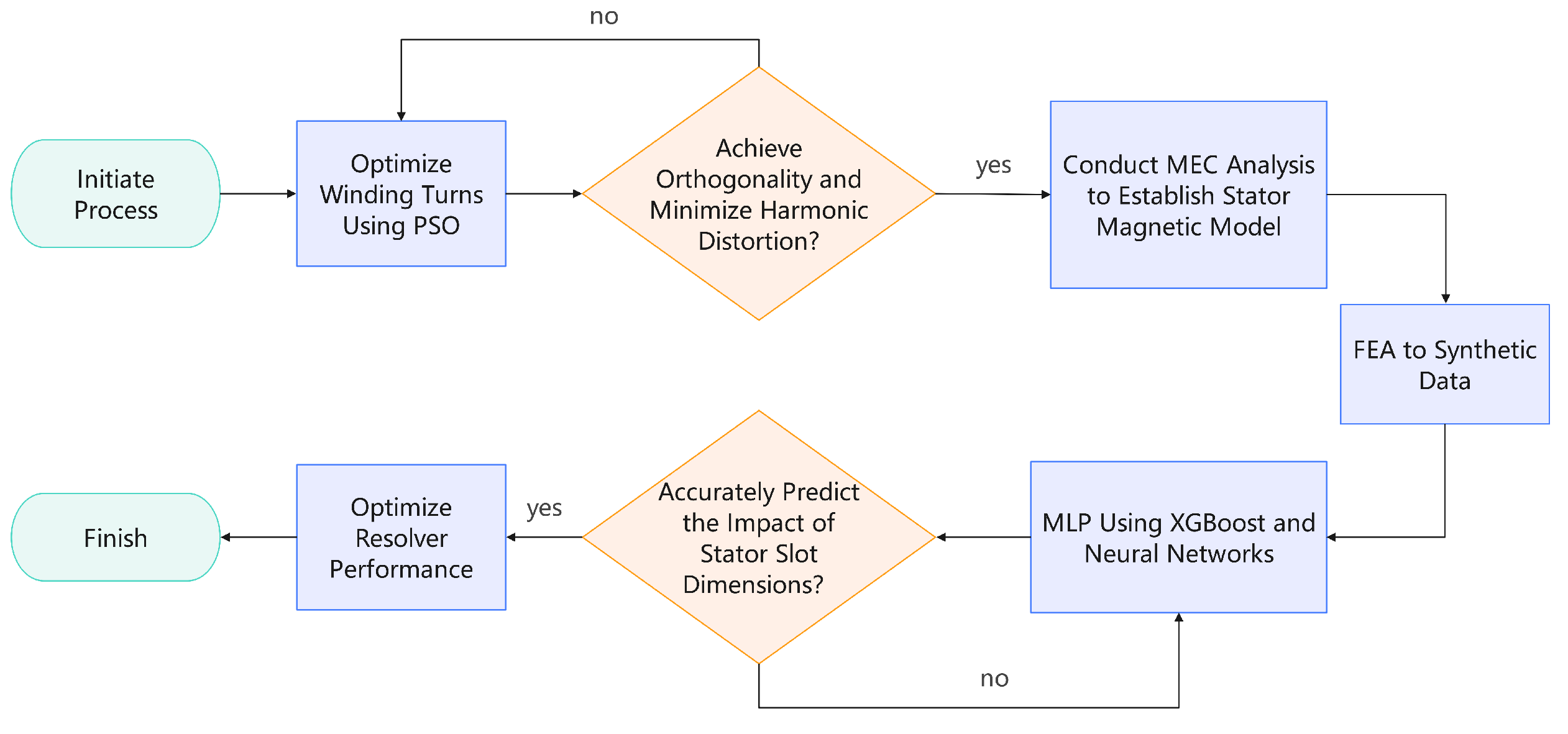
4. Benefits of the Integrated Approach: The integrated optimization framework, as shown in
Figure 5, demonstrates the synergy between each step in the process. PSO provides an optimized winding configuration that minimizes harmonic distortion. MEC offers a detailed understanding of the magnetic circuit and slot leakage flux, and machine learning allows for the precise optimization of the stator slot shape. Together, these techniques create a comprehensive, data-driven process that significantly improves resolver accuracy while reducing harmonic content. This leads to superior performance in applications requiring high-precision motor control.
By combining global search algorithms like PSO with detailed magnetic analysis and advanced predictive modeling, this framework provides an efficient pathway to optimizing the SSPWMW-VRR design. The resulting system is both robust and adaptable, capable of achieving high accuracy without the need for extensive physical testing or iterative design adjustments.
2. Experimental Design and Results Analysis
This section provides an in-depth analysis of the results obtained from the PSO, MEC, and machine learning optimizations discussed in the previous section.
2.1. PSO Results and Winding Turn Optimization
After running PSO for winding optimization, a significant reduction in harmonic distortion and improved orthogonality were achieved. The optimized winding configurations were validated through analytical calculations and simulation data, demonstrating marked improvements in resolver accuracy.
By varying the winding distribution coefficient
within a range of 20 to 500 using PSO, the algorithm seeks values that minimize the inner product of the sine and cosine windings and ensure the balance of positive and negative turns. As the winding configurations are discrete, only specific
values satisfy both these conditions.
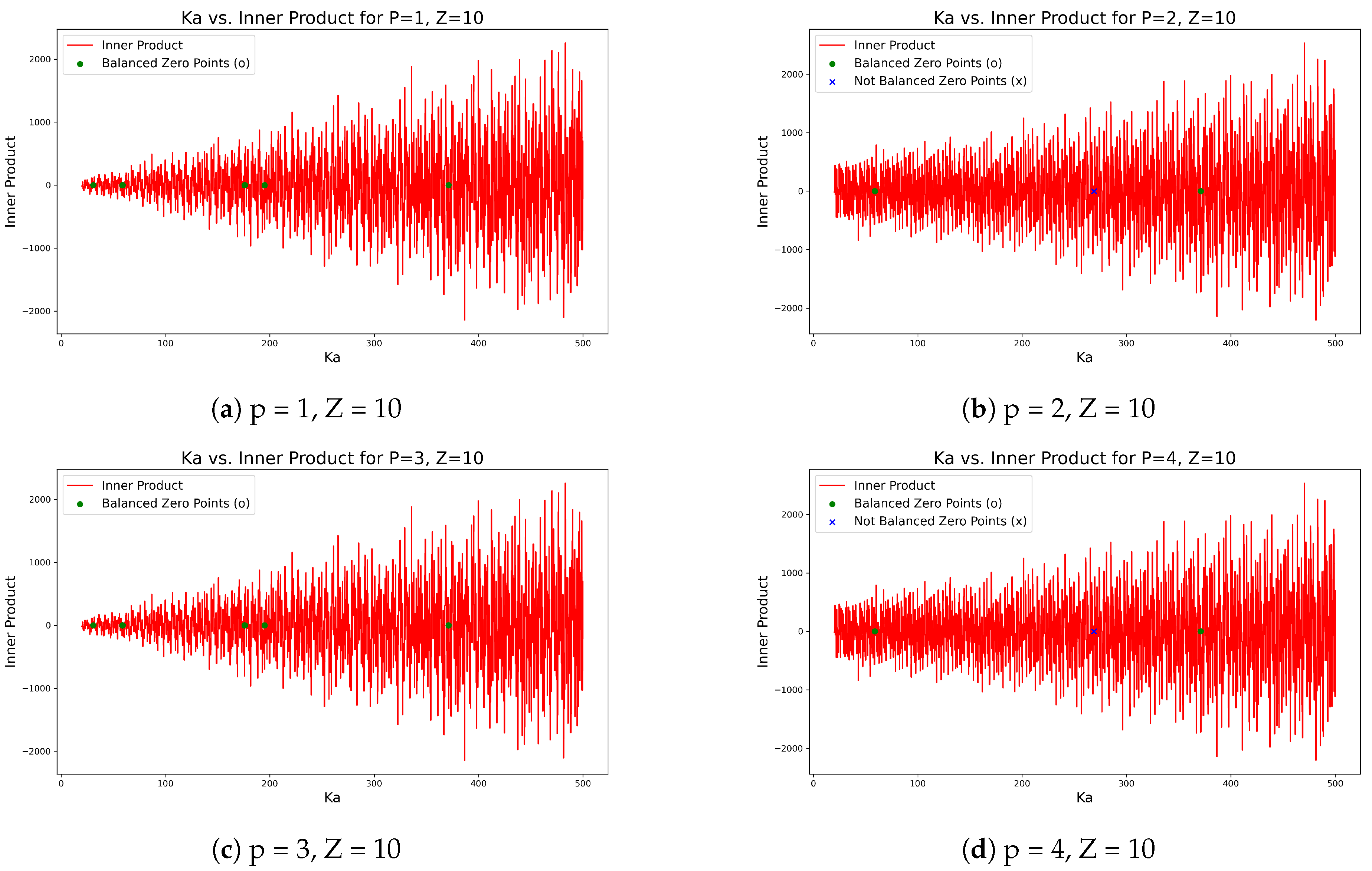
Figure 6 illustrates the distribution of
values for multiple pole-pair configurations in a 10-slot stator, highlighting the instances where the inner product is zero and the sum of positive and negative turns is balanced, thus achieving orthogonality and symmetry.
The PSO optimization was performed for 1-pole, 2-pole, 3-pole, and 4-pole configurations with a 10-slot stator. The results reveal significant differences between odd and even pole-pair configurations in terms of achieving optimal values that satisfy both the inner product and winding turn balance conditions.
1-Pole, 10-Slot Configuration: The PSO results for the 1-pole, 10-slot configuration identified five values where the inner product equals zero and the sum of positive and negative turns is perfectly balanced (i.e., the sum is zero). This suggests that achieving orthogonality and symmetry is more straightforward in odd-pole configurations like the 1-pole setup.
2-Pole, 10-Slot Configuration: For the 2-pole, 10-slot configuration, two values resulted in zero inner product and balanced positive and negative winding turns. However, there was also one case where the inner product was zero, but the positive and negative turns were not balanced, indicating an imbalance in the winding distribution. This suggests that while even-pole configurations can achieve orthogonality, they are more prone to winding turn imbalances.
3-Pole, 10-Slot Configuration: In the 3-pole, 10-slot configuration, similar to the 1-pole case, five values were found where both the inner product was zero and the positive and negative turns were balanced. The results reinforce the observation that odd-pole configurations have a higher likelihood of achieving both orthogonality and symmetry.
4-Pole, 10-Slot Configuration: For the 4-pole, 10-slot configuration, two values resulted in both zero inner product and balanced winding turns, while one case exhibited zero inner product but an imbalance between the positive and negative turns. This pattern is consistent with the 2-pole configuration, where even-pole configurations tend to face more challenges in achieving winding symmetry.
The analysis reveals that odd pole-pair configurations (1-pole and 3-pole) have more instances of values that satisfy both orthogonality (zero inner product) and symmetry (balanced positive and negative turns), making them more favorable for achieving optimal winding design. In contrast, even pole-pair configurations (2-pole and 4-pole) tend to show fewer instances of balanced turns, despite achieving orthogonality, which makes them less optimal in simultaneously fulfilling both conditions. These insights provide valuable guidance for optimizing resolver winding designs, especially when selecting the appropriate pole-pair and slot combinations.
2.2. MEC Analysis and Slot Leakage Flux Optimization
Following the PSO optimizations, the MEC method was applied to reduce slot leakage flux. The first leakage circuit passes from tooth top i to tooth top i+1. The second leakage circuit passes through the gap between the excitation and signal windings, entering tooth i. The third leakage circuit starts from tooth top i, passes through the slot and slot bottom and enters the stator yoke. The transmission and distribution of leakage flux can be affected by adjusting the size of the magnetic slot wedge and the gap between it and the slot bottom, thereby influencing SSPWMW-VRR performance and output. If we consider exciting current
as
=
, where I is amplitude, and
is the angular frequency, the total magneto motive force F can be expressed as:
Here,
represents the total magnetic flux, and
denotes the total magnetic conductance.
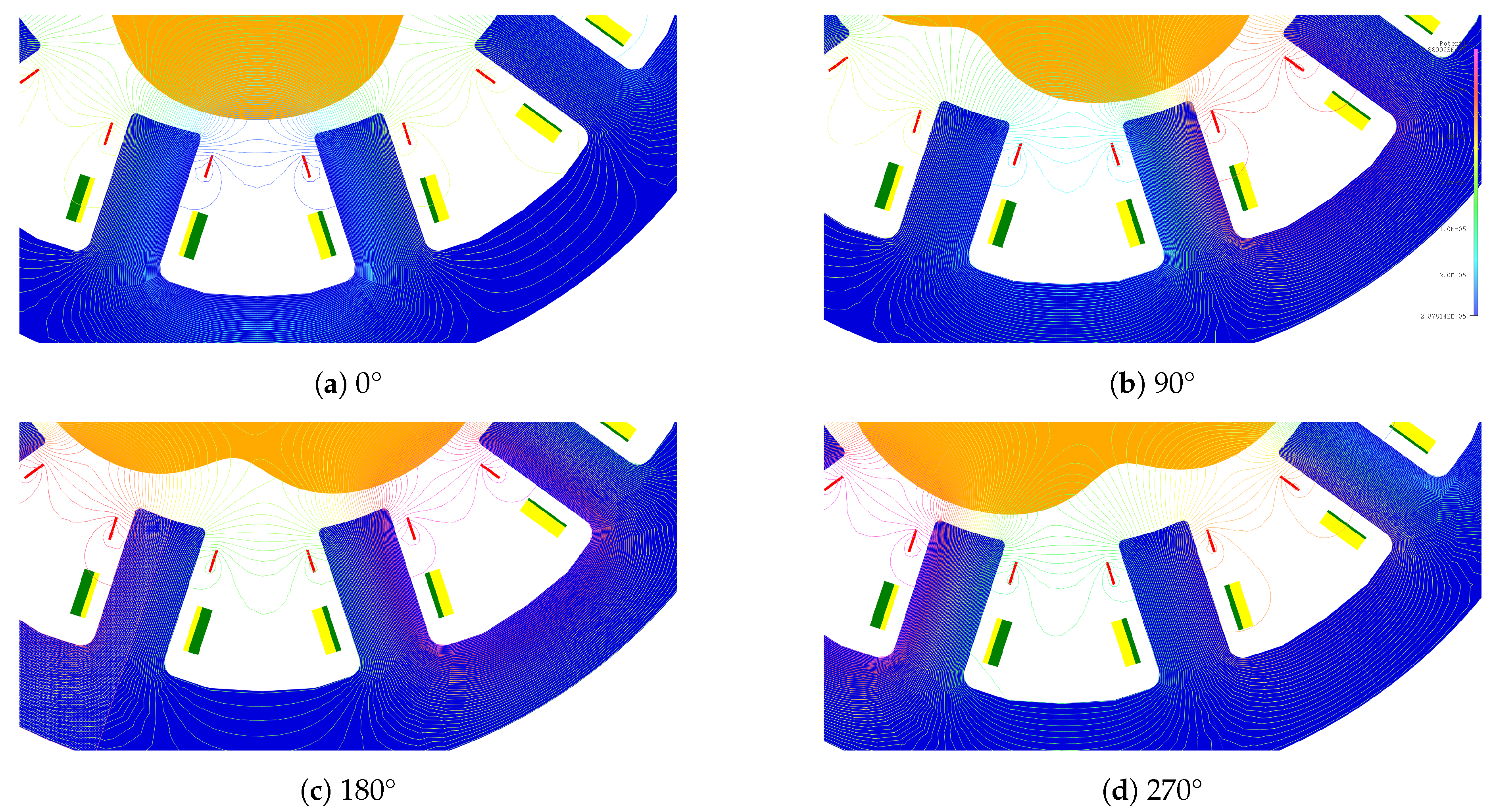
Figure 7 shows the air gap magnetic field distribution when the rotor salient pole’s centerline corresponds to the slot centerline at 0°, 90°, 180°, and 270° positions, allowing for a detailed observation of how the slot leakage flux fluctuates with the rotation of the salient pole rotor. To accurately analyze this phenomenon, an equivalent magnetic circuit model based on the variations in the slot leakage flux was established. As shown in
Figure 2, this study introduces
, and
within the slot to comprehensively describe the influence of the slot leakage flux on the output signal. Unlike conventional motor slot leakage inductance, the asymmetrical positions of
and
at opposite sides of the slot opening are due to the salient pole effect. Assuming a minimal influence of the salient pole on the slot leakage flux, it can be approximated that
is equivalent and
can also be treated as approximately similar. To simplify the analysis, a star-to-delta
transformation is applied to certain sections of some components.
Figure 8 shows the resultant simplified equivalent magnetic circuit. Observation reveals that the induced voltage on the secondary winding considering
,
, and
linked with turns can be expressed as follows:
Here,
can be expressed as:
can be expressed as:
and
can be expressed as:
In the expressions,
Here,
,and
represent the magnetic conductance of the tooth signal winding section, tooth magnetizing winding section, rotor, and stator core yoke , respectively;
,and
represent the corresponding core magnetic path lengths at their positions. A denotes the cross-sectional area of the iron core.
denotes the magnetic permeance of the magnetic slot wedge expressed as follows:
Here,
represents the relative magnetic permeability of the magnetic slot wedge;
denotes the cross-sectional area of the slot wedge;
denotes the width of the slot wedge. Given that
and
are connected in parallel, a composite magnetic permeance
can be derived accordingly as (12).
Due to the convex pole effect, assuming that the leakage flux path of the slot can be approximated as a Witch of Agnesi curve ,
can be expressed as follows:
The a value in the Cartesian equation
changes with the convex pole effect and can be expressed as (14):
Similarly,
and
can be expressed as follows:
Additionally, the magnetic fluxes
and
at both ends of the magnetic slot wedge display periodic changes similar to
due to variations in the salient pole rotor position. The model comprises essential elements, such as segmented winding, sinusoidal and cosine distribution winding, and magnetic slot wedges that limit fluctuations in slot leakage flux while accounting for the influence of the salient pole rotor position on magnetic fluxes and conductance.
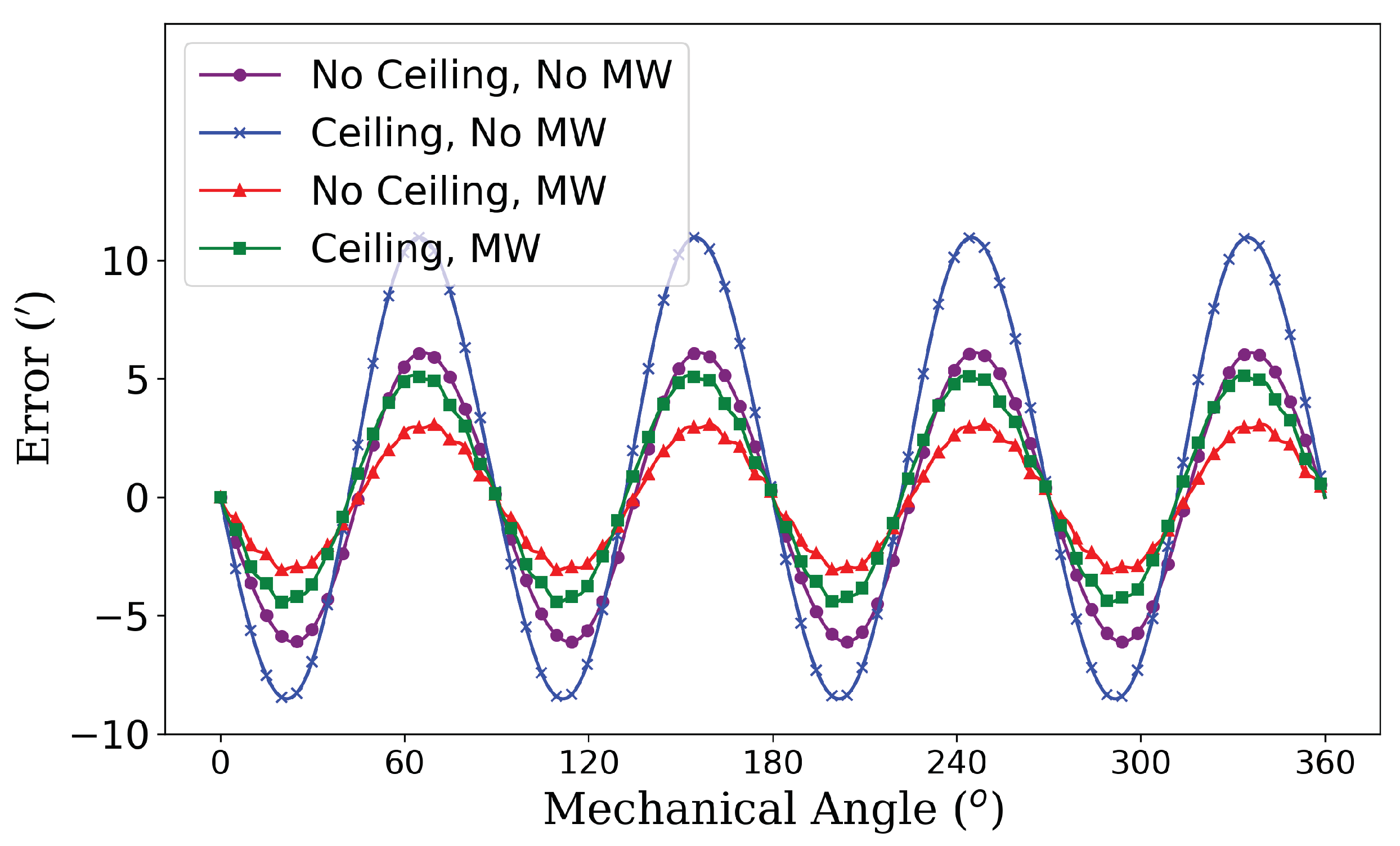
Figure 9 depicts errors obtained using the values from Table II to compute an analytical model.
Table 1.
Geometrical parameters of the studied resolver.
Table 1.
Geometrical parameters of the studied resolver.
| Parameter |
Definition |
Value |
Unit |
| L |
Core stack length |
7.0 |
mm |
|
Stator outer diameter |
37.0 |
mm |
|
Stator inner diameter |
10 |
mm |
|
Air-gap length factor |
1.5 |
mm |
|
Air-gap shape factor |
0.65 |
mm |
|
Number of Pole Pairs |
4 |
|
|
Number of Slots |
10 |
|
|
Iron relative permeability |
5000 |
|
|
Permalloy relative permeability |
20000 |
|
|
Excitation winding parameter |
15 |
|
|
Signal winding sine distribution parameter |
58.7 |
|
|
Ex Winding length |
2.0 |
mm |
|
Signal Winding length |
3.0 |
mm |
|
Magnetic slot wedge thickness |
0.05 |
mm |
|
Magnetic slot wedge width |
1.4 |
mm |
|
Magnetic slot wedge distance from slot opening |
0 |
mm |
Despite challenging calculations involving numerous variables, the MEC model offers valuable insights into the impact of various design parameters on SSPWMW-VRR performance through its magnetism attributes.
Figure 9 shows that rounding off turns in the winding decreases output signal accuracy, similar to that observed with conventional VRR; however, incorporating magnetic slot wedges at slot openings helps mitigate this effect by enhancing signal precision. Utilizing optimization studies along with performance evaluation using MEC models combined with FEA allows a more precise examination of the electric circuit properties.
2.3. Electromagnetic Field Simulation and Dataset Construction
In advancing the resolver optimization process, we constructed an artificial dataset by systematically varying key stator slot parameters using Finite Element Analysis (FEA) simulations. The dimensions of the stator slots—including slot width (), jaw width (), slot wedge thickness (), and the spacing between windings—are crucial in determining the resolver’s performance. These parameters influence magnetic flux distribution, leakage flux, and the electromagnetic coupling between the stator and rotor.
2.3.1. Simulation Process and Parameter Selection
The simulation process was structured into the following stages:
Input Parameter Variations: We systematically varied key stator slot dimensions to generate multiple resolver designs. The parameters were adjusted based on the ranges and step sizes outlined in
Table 2.
FEA Simulation: Each design configuration was evaluated using FEA simulations, providing detailed analyses of electromagnetic behavior, including magnetic flux distribution and performance metrics such as torque ripple and induced voltage.
Data Collection: The simulation results were compiled into a dataset containing both the input parameters (stator slot dimensions) and the output performance metrics (e.g., magnetic flux densities, torque ripple, induced voltage waveforms, and position errors).
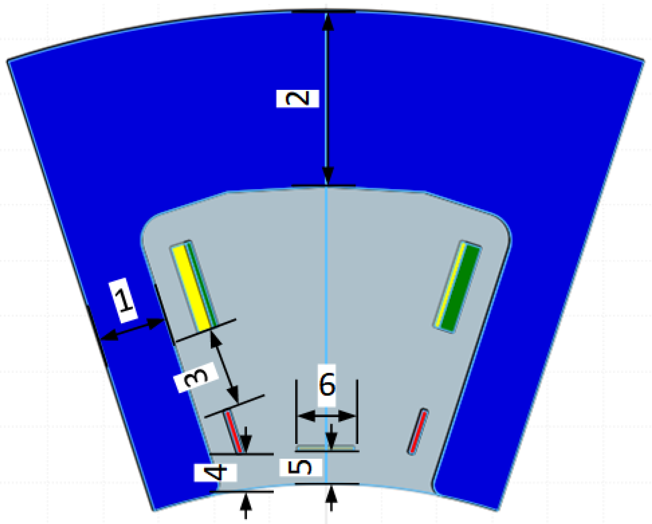
The key parameters selected for optimization are summarized in
Table 2, and their physical representations are illustrated in
Figure 10.
2.3.2. Dataset Construction and Analysis
The dataset generated from Finite Element Analysis (FEA) simulations captures the intricate relationships between stator slot design and resolver performance metrics. These metrics serve as output features for machine learning models used to optimize resolver design. To better understand the initial performance characteristics before optimization, the dataset was analyzed using statistical visualizations.
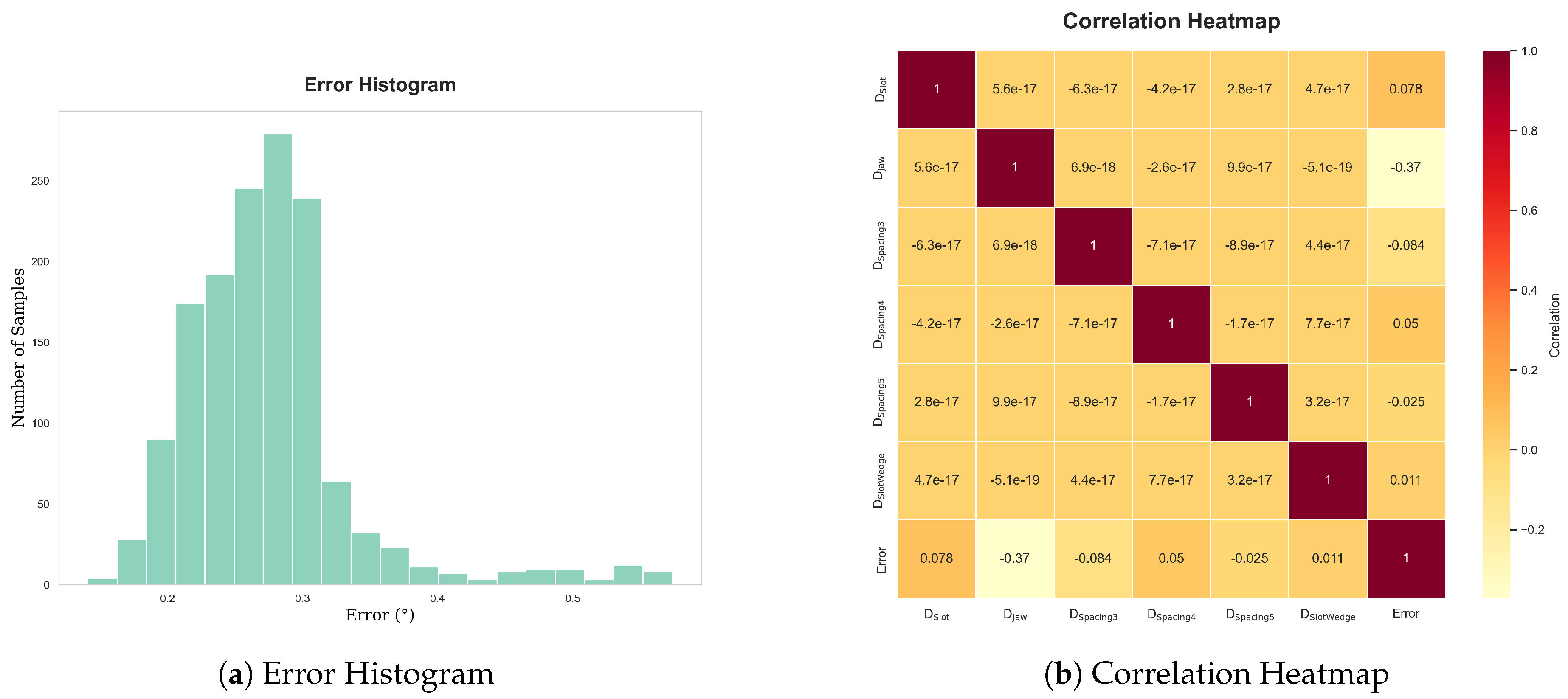
Error Distribution: The error distribution, shown in
Figure 11, provides insight into the spread and frequency of different error magnitudes. By identifying prevalent error ranges, this analysis helps highlight areas that require further optimization.
Parameter Correlations: The correlation heatmap (
Figure 11) highlights relationships between key stator slot parameters and resolver errors. Understanding these correlations enables efficient prediction of how changes in one parameter affect others, influencing overall resolver accuracy.
-
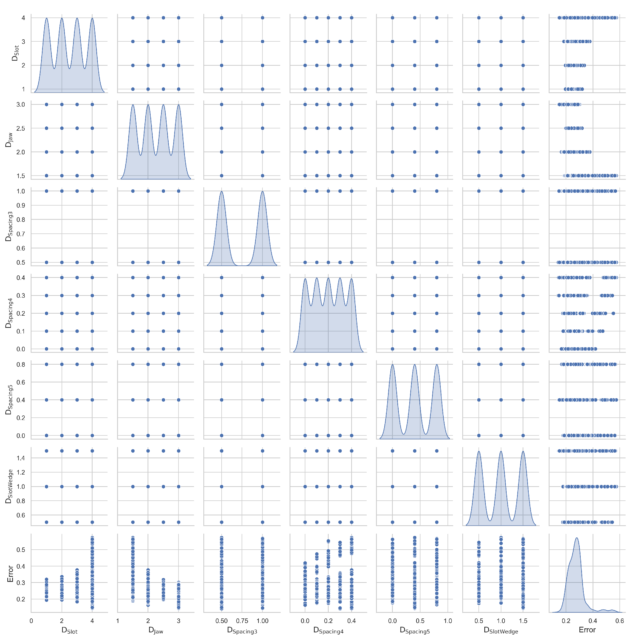
Parameter Relationships: The scatter plot matrix (
Figure 12) illustrates pairwise relationships between the stator slot parameters. This analysis helps identify patterns and interactions that may significantly influence resolver performance.
These insights formed the basis for the machine learning model development, revealing key parameters that influence resolver performance. By leveraging this dataset, the optimization of stator slot designs is guided by both empirical data and machine learning predictions to enhance resolver accuracy.
2.4. Machine Learning-Based Stator Slot Shape Optimization
These insights formed the basis for the machine learning model development, revealing key parameters that influence resolver performance. By leveraging this dataset, the optimization of stator slot designs is guided by both empirical data and machine learning predictions to enhance resolver accuracy.
2.4.1. XGBoost Model for Error Prediction
XGBoost is an ensemble algorithm known for its efficiency in handling large datasets with complex features. In this study, XGBoost was employed to model the relationship between stator slot parameters and the position error of the VRR.The input features for the model included:
Stator Slot Dimensions: Slot width (), jaw width (), and slot wedge thickness ().
Winding Spacings: Spacing between signal and excitation windings (), spacing between excitation winding and stator inner diameter (), and spacing between slot wedge and stator inner diameter ().
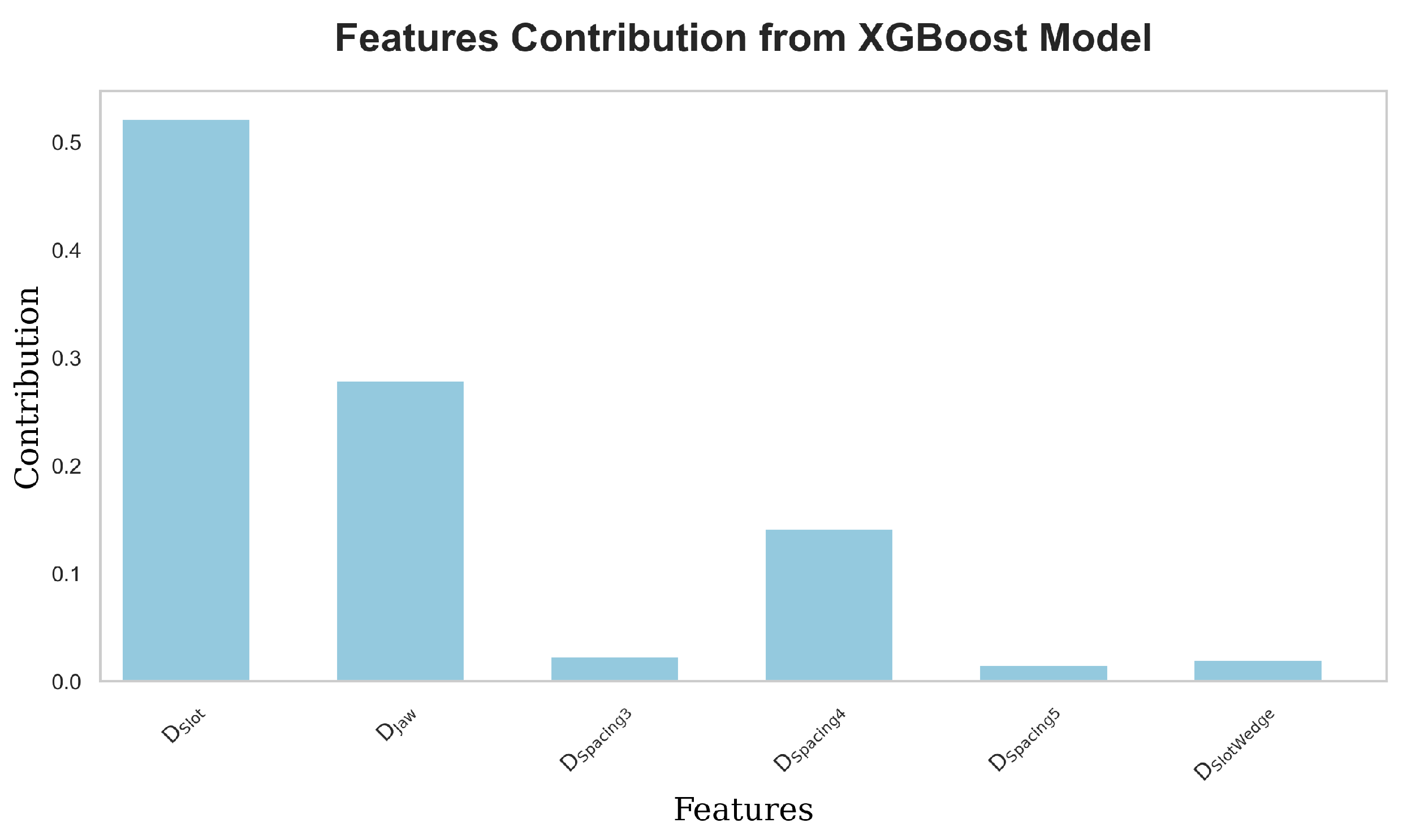
The model’s target variable was the position error obtained from FEA simulations. After training, the XGBoost model was capable of predicting position errors quickly, eliminating the need for repeated, time-consuming FEA simulations. The feature contribution analysis (
Figure 13) identified the most influential parameters for resolver accuracy, offering critical insights for further optimization.
2.4.2. Multi-Layer Perceptron for Complex Parameter Optimization
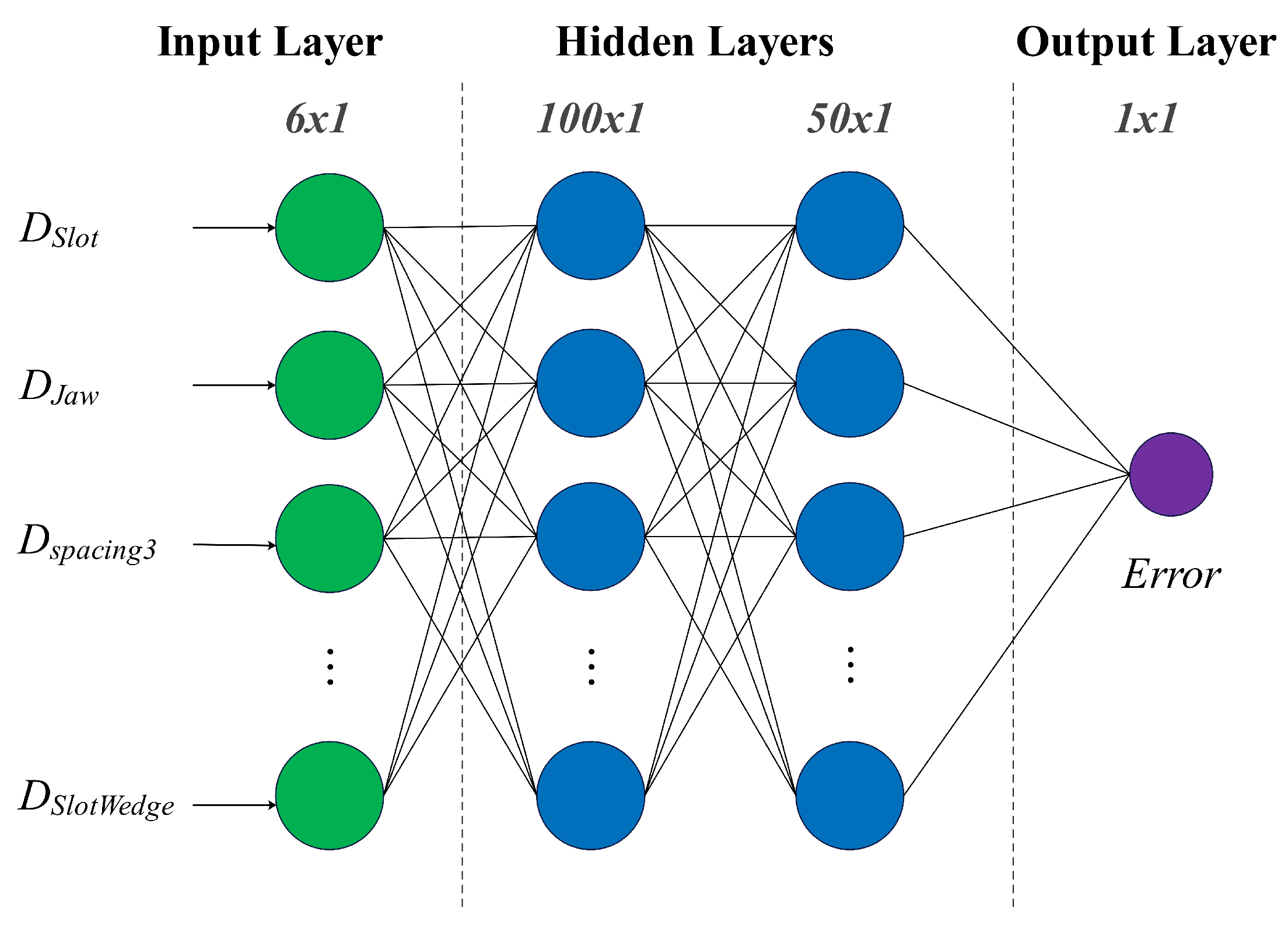
To capture complex nonlinear relationships between the stator slot parameters and position error, a Multi-Layer Perceptron (MLP) model was employed. The MLP model, with its multi-layer architecture, is well-suited for learning intricate patterns from the dataset.The MLP model structure consists of:
Input Layer: Six neurons corresponding to the six slot design parameters (, , , , , and ).
Hidden Layers: The number of neurons and layers was optimized using GridSearchCV.
Output Layer: A single neuron representing the position error.
The MLP used ReLU activation functions for nonlinearity and the Adam optimizer to minimize the mean squared error (MSE) loss function, improving model convergence and prediction accuracy (
Figure 14).
2.4.3. Model Performance Comparison and FEA Validation
Both models were evaluated based on predictive accuracy, convergence speed, and computational efficiency. The key performance metrics used for comparison were Mean Absolute Error (MAE) and Root Mean Squared Error (RMSE).
XGBoost Model: Demonstrated faster training and prediction times, efficiently handling the dataset and providing clear feature contribution insights. It is especially effective for capturing simple relationships between parameters and outputs.
MLP Model: Exhibited superior performance in modeling more complex nonlinear interactions among parameters. However, it required longer training times and greater computational resources.
To validate the optimized designs from the machine learning models, FEA simulations were conducted. Key performance indicators assessed included a comparison between the model predictions and the FEA results. The results from the simulations revealed substantial improvements in the optimized designs:
Reduction in position errors.
Enhanced signal orthogonality.
Lower harmonic distortion in induced voltages.
The effectiveness of the machine learning-driven optimization is demonstrated in
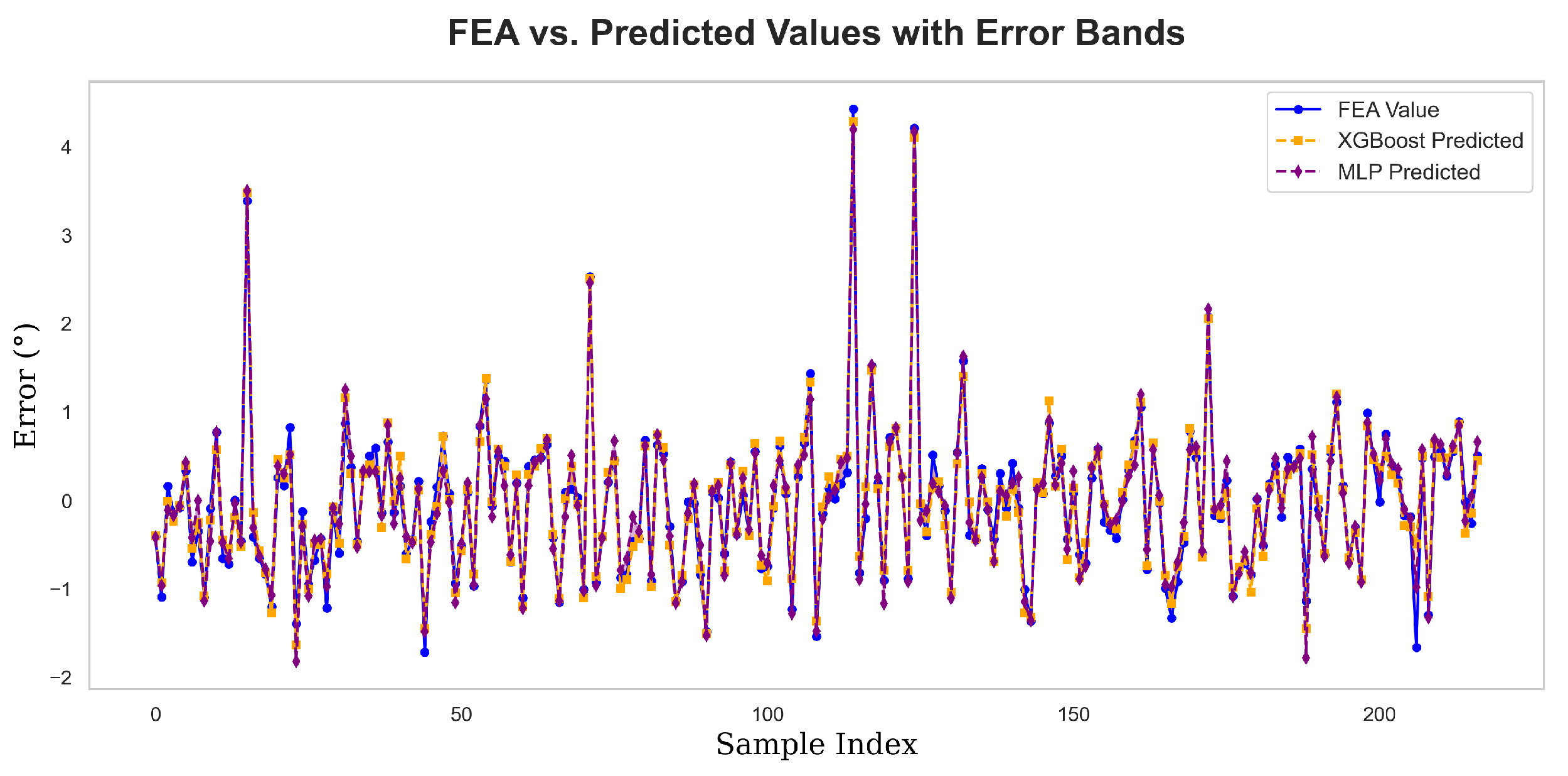
Figure 15, which compares the predicted values from both the XGBoost and MLP models with the actual results from the FEA simulations. Both models exhibit a high degree of trend consistency with the FEA values, with only minimal differences. This strong alignment and low discrepancy between the predicted values and the FEA results highlight the success of both models in achieving accurate predictions.
The analysis of
Figure 16 and
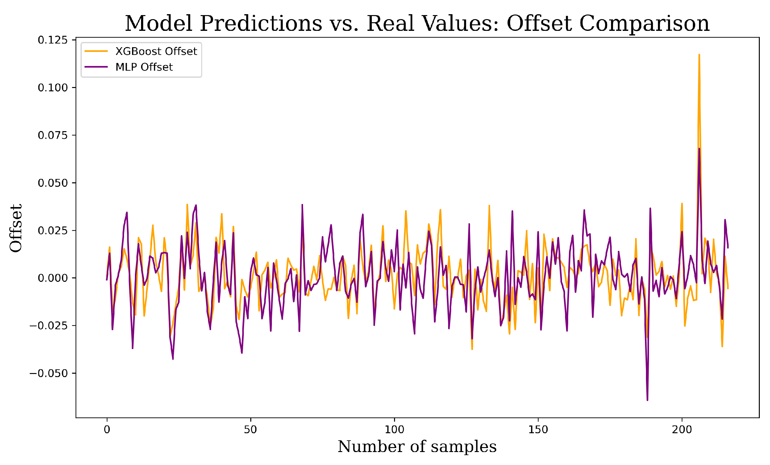
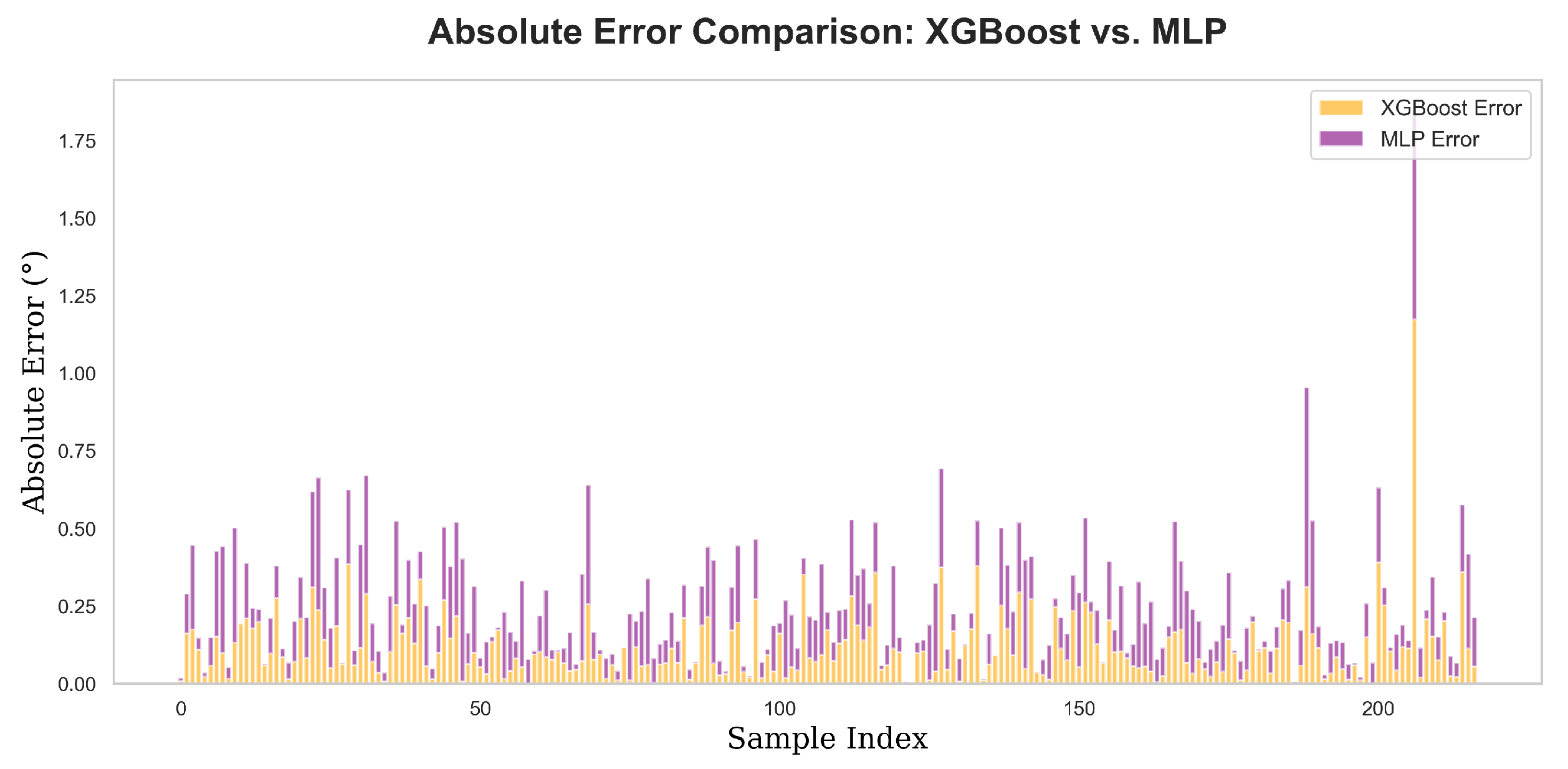
Figure 17 provides a detailed comparison of the offset and absolute error between the XGBoost and MLP model predictions with the actual FEA values.
In
Figure 16, the offset comparison illustrates how the predictions from both models deviate from the FEA values. The plot shows that while both models follow the overall trend of the FEA results, the XGBoost model consistently exhibits smaller offsets. This suggests that XGBoost is more effective at minimizing prediction errors and maintaining a closer alignment with the true FEA values.
Figure 17 further supports this conclusion by comparing the absolute errors between the two models. The graph highlights the differences in prediction accuracy, with the XGBoost model demonstrating a lower absolute error across most data points. This suggests that XGBoost provides more reliable predictions compared to the MLP model when applied to the optimization of stator slot parameters.
Moreover, when examining the overall prediction performance through the Mean Absolute Error (MAE), the XGBoost model achieved an MAE of 0.1172, whereas the MLP model had a slightly higher MAE of 0.1258. This small but significant difference in MAE values indicates that while both models perform well, the XGBoost model outperforms the MLP model in terms of prediction accuracy, making it a more effective choice for this particular optimization task.
In summary, both visual and numerical analyses show that the XGBoost model provides better optimization results, reducing errors more effectively and aligning more closely with FEA simulation values.
2.4.4. Experimental Results and Discussion
Following the optimization of the stator slot design using the machine learning models, prototypes of the SSPWMW-VRR were manufactured based on the optimized parameters. These prototypes were then tested to validate the effectiveness of the optimization process in comparison with a conventional VRR.
Figure 18 shows the experimental setup for testing the SSPWMW-VRR prototype on a high-precision rotary table. To reduce the influence of eccentricity on the output signal, fine adjustments were made to the center position of the resolver using a two-axis horizontal slide table. Any static installation eccentricity was minimized by precisely aligning the stator and shaft.
Figure 18 displays the dynamic test system for evaluating the prototype.
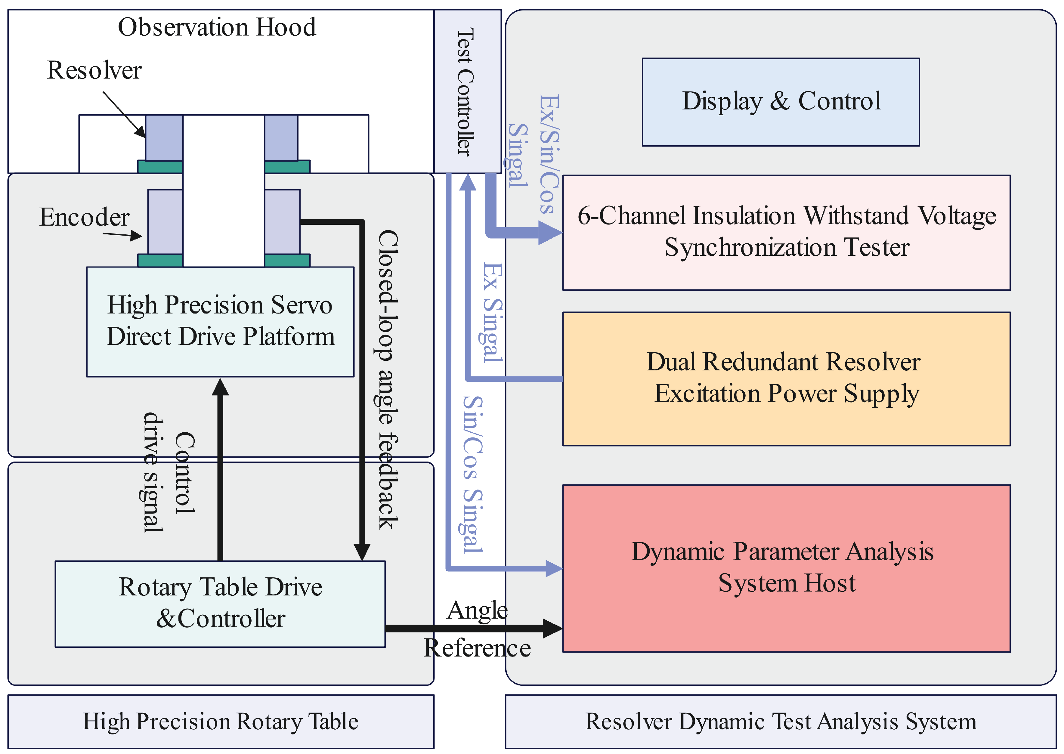
The structure of the dynamic test system is shown in
Figure 19. The setup includes a High-Precision Rotary Table that synchronously drives both the resolver and an encoder. The system is designed to generate stable excitation signals, sample resolver output synchronously, and decode the resolver’s position using a high-precision 32-bit encoder to calculate error deviations.
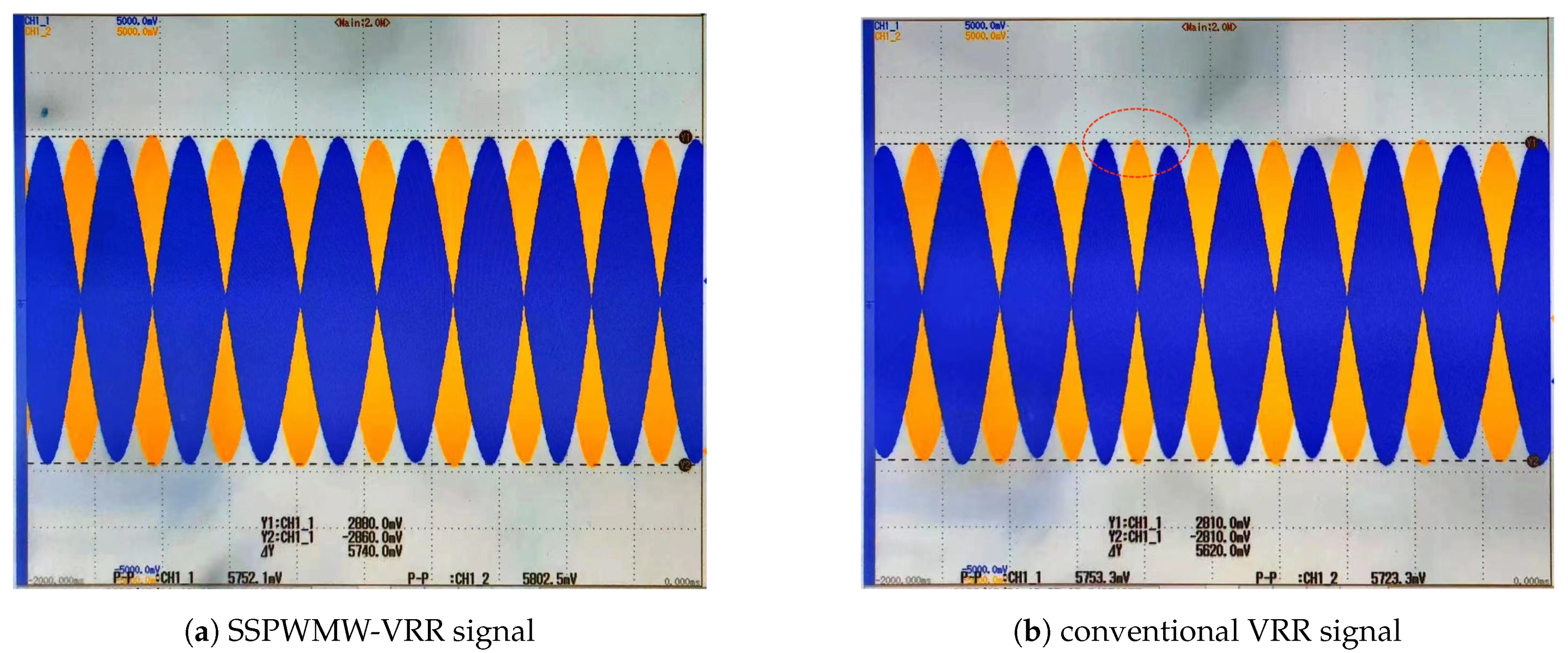
As shown in
Figure 20, the oscilloscope captures the waveform from the SSPWMW-VRR prototype, demonstrating significant improvements in signal stability when compared to the conventional VRR output (
Figure 20). The optimized design effectively reduces amplitude and phase variations, highlighting the success of the machine learning-driven optimization process. Comparative experiments were conducted on resolvers with a 37-mm outer diameter to evaluate the accuracy of the optimized design, with prototypes of the conventional VRR and SSPWMW-VRR being tested.
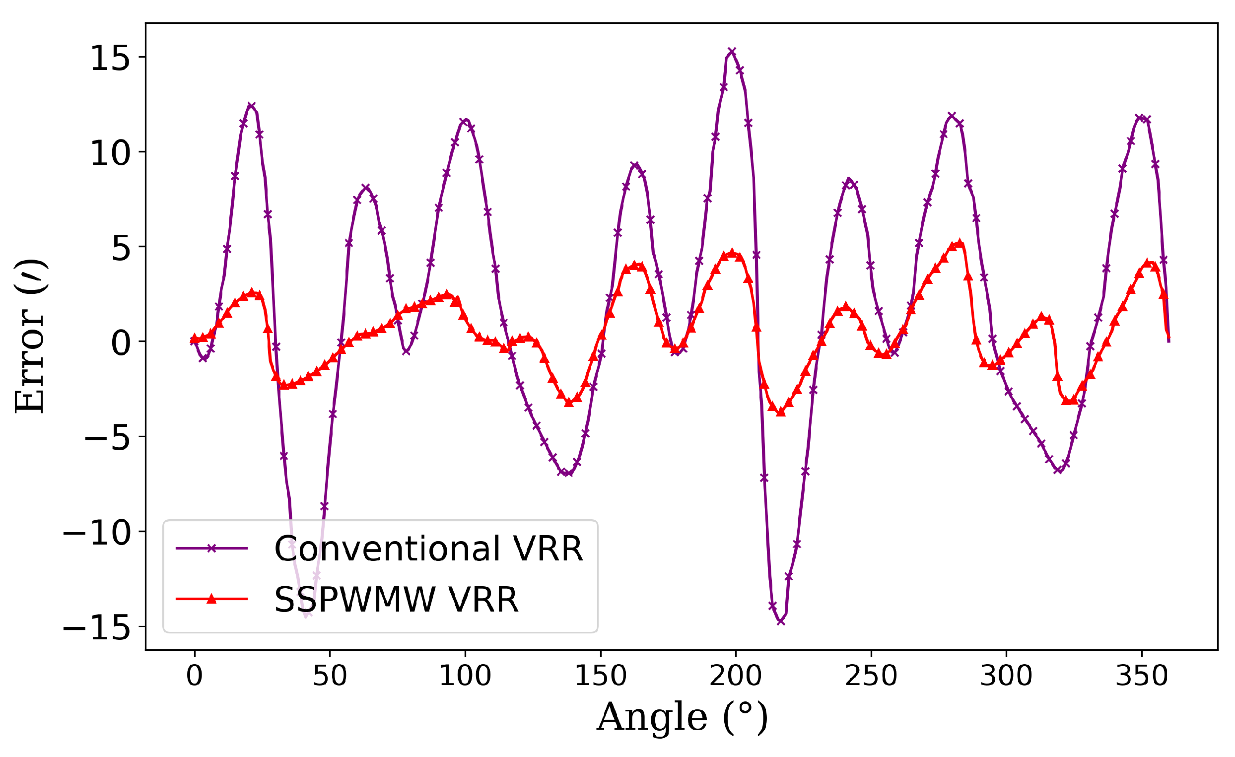
The error evaluation in
Figure 21 indicates that the maximum error in the output signal is not confined to zero position or fixed angle positions, as was often assumed in traditional methods. The use of RDC (Resolver-to-Digital Converter) calculations allows for a more accurate understanding of continuous signal variations and their associated errors. While the conventional VRR demonstrated an error of ±30’, the SSPWMW-VRR prototype significantly reduced this to ±5’, further validating the effectiveness of the optimized design.
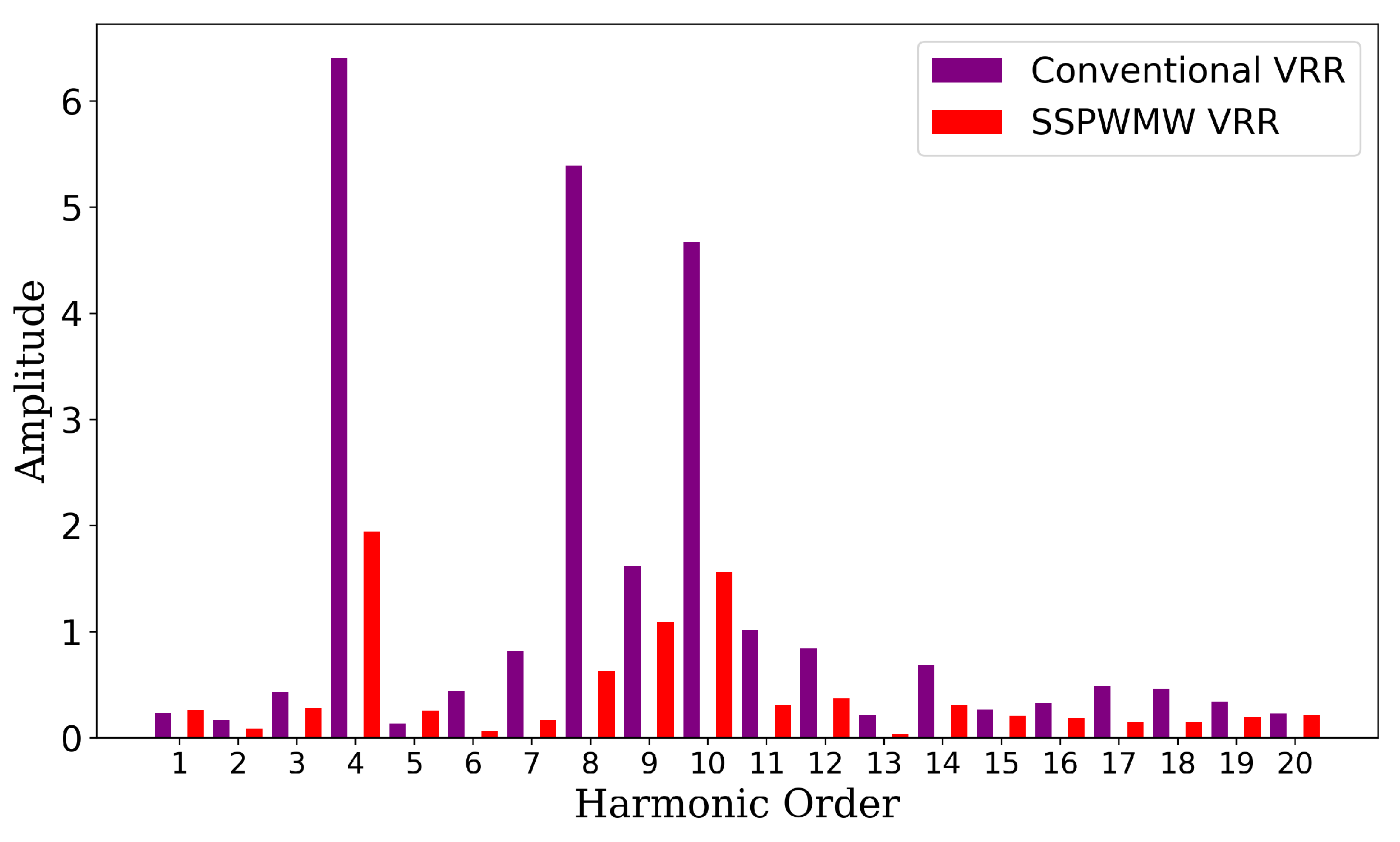
Harmonic analysis, shown in
Figure 22, further supports these findings. The fourth harmonic, primarily attributed to slot leakage flux, was present in all VRR prototypes. The conventional VRR exhibited the highest harmonic amplitude of 6.40, with multiple significant harmonic components. In contrast, the SSPWMW-VRR prototype reduced the harmonic amplitude to 1.94 and showed fewer significant harmonics. These results underscore the improvement in signal quality and reduction in error magnitudes achieved through the optimization process.
In summary, the experimental results demonstrate the effectiveness of the machine learning-driven optimization algorithm. By comparing the optimized SSPWMW-VRR prototype to a conventional VRR, it is clear that the SSPWMW-VRR offers superior accuracy and signal stability, with significantly lower errors and reduced harmonic distortion. These findings validate the practical application of the optimization techniques developed in this study.
3. Conclusions
In this study, the performance of a Segmented Sinusoidal Parameter Winding with Magnetic Wedge Variable Reluctance Resolver (SSPWMW-VRR) was optimized through a multi-layered approach, integrating Particle Swarm Optimization (PSO), Magnetic Equivalent Circuit (MEC) analysis, and advanced machine learning techniques such as XGBoost and Multi-Layer Perceptron (MLP). The goal was to address the design limitations of conventional VRRs, particularly issues related to winding asymmetry, signal orthogonality, and harmonic distortions.
The Particle Swarm Optimization (PSO) algorithm was instrumental in optimizing the winding distribution to achieve sinusoidal orthogonality and minimize harmonic distortion. MEC analysis further provided detailed insights into the magnetic behavior within the stator slots, enabling the fine-tuning of slot leakage flux, thereby improving the overall electromagnetic performance. The application of machine learning techniques, particularly XGBoost and MLP, was a key innovation in this research. These models allowed for precise optimization of the stator slot shape, reducing the reliance on traditional trial-and-error methods and extensive physical simulations.
The optimized designs were validated through Finite Element Analysis (FEA) simulations and real-world experimental tests. The machine learning models demonstrated a high degree of accuracy, with XGBoost exhibiting a Mean Absolute Error (MAE) of 0.1172, compared to 0.1258 for MLP, thus confirming that XGBoost provided superior performance in this context. Experimental results further validated the efficacy of the optimized design, as the SSPWMW-VRR prototype achieved a significant reduction in position errors (from ±30’ to ±5’) and harmonic distortion compared to a conventional VRR.
Overall, this study demonstrates the potential of combining optimization algorithms, detailed electromagnetic modeling, and machine learning techniques to improve the design and performance of VRRs. The proposed SSPWMW-VRR exhibits enhanced accuracy, signal stability, and reduced harmonic content, making it a promising solution for high-precision applications such as electric vehicles and aerospace systems.
Future work could focus on expanding this optimization framework to other types of electrical machines and exploring hybrid machine learning models for even more refined design improvements. Additionally, further investigation into reducing computational overhead and speeding up the optimization process could enhance the applicability of this methodology in industrial design processes.
Author Contributions
All authors contributed equally to the concept of the paper and investigation of methodologies, writing, and drawing of figures; original draft preparation and editing, conceptualization, investigation, and methodology W.L.; supervision, project administration, funding acquisition, writing—review, S.H.; machine learning algorithm development, synthetic data generation, and validation, S.Y.; implementation of Particle Swarm Optimization (PSO) algorithms and parametric modeling using Finite Element Analysis (FEA), Q.L. All authors have read and agreed to the published version of the manuscript.
Funding
This research was funded by National Natural Science Foundation of China grant number 52107112.
Institutional Review Board Statement
Not applicable.
Informed Consent Statement
Not applicable.
Data Availability Statement
Not applicable..
Conflicts of Interest
The authors declare no conflicts of interest.
Abbreviations
The following abbreviations are used in this manuscript:
| VRRs |
Variable Reluctance Resolvers |
| EVs |
Electric Vehicles |
| PMSMs |
Permanent Magnet Synchronous Motors |
| FEA |
Finite Element Analysis |
| AI |
Artificial Intelligence |
| ML |
Machine Learning |
| NSGA-II |
Non-dominated Sorting Genetic Algorithm II |
| XGBoost |
Extreme Gradient Boosting |
| SSPWMW |
Segmented Sinusoidal Parameter Winding with Magnetic Wedge |
| PSO |
Particle Swarm Optimization |
| MEC |
Magnetic Equivalent Circuit |
| PCB |
Printed Circuit Board |
| NN |
Neural Networks |
| MLP |
Multi-Layer Perceptron |
| DNN |
Deep Neural Network |
| MAE |
Mean Absolute Error |
| RMSE |
Root Mean Square Error |
| MSE |
Mean Squared Error |
| SGD |
Stochastic Gradient Descent |
References
- Ge, X.; Zhu, Z.Q.; Ren, R.; Chen, J.T. A Novel Variable Reluctance Resolver for HEV/EV Applications. IEEE Transactions on Industry Applications 2016, 52, 2872–2880. [Google Scholar] [CrossRef]
- Kim, K.C.; Hwang, S.J.; Sung, K.Y.; Kim, Y. A study on the fault diagnosis analysis of variable reluctance resolver for electric vehicle. SENSORS, 2010 IEEE, 2010, pp. 290–295. [CrossRef]
- Kim, K.C. Analysis on the Charateristics of Variable Reluctance Resolver Considering Uneven Magnetic Fields. IEEE Transactions on Magnetics 2013, 49, 3858–3861. [Google Scholar] [CrossRef]
- Kim, J.; Lee, C. Angular position error detection of variable reluctance resolver using simulation-based approach. International Journal of Automotive Technology 2013, 14, 651–658. [Google Scholar] [CrossRef]
- Tootoonchian, F. Design and Optimization of a Multi-Turn Variable Reluctance Resolver. IEEE Sensors Journal 2019, 19, 7275–7282. [Google Scholar] [CrossRef]
- Neidig, N.; Wanke, A.; Werner, Q.; Doppelbauer, M. Influence of a variable reluctance resolver on an E-motor-system. 2016 18th European Conference on Power Electronics and Applications (EPE’16 ECCE Europe), 2016, pp. 1–10. [CrossRef]
- Xiao, L.; Li, Z.; Bi, C. Optimization of a Reluctance Resolver. 2018 Asia-Pacific Magnetic Recording Conference (APMRC), 2018, pp. 1–2. [CrossRef]
- Nasiri-Gheidari, Z.; Alipour-Sarabi, R.; Tootoonchian, F.; Zare, F. Performance Evaluation of Disk Type Variable Reluctance Resolvers. IEEE Sensors Journal 2017, 17, 4037–4045. [Google Scholar] [CrossRef]
- Tootoonchian, F. Proposal of new windings for 5-X variable reluctance resolvers. IET Science, Measurement & Technology 2018. [Google Scholar] [CrossRef]
- Tolstykh, O.A.; Balkovoi, A.P.; Tiapkin, M.G.; Markov, A.S. Research and development of the 4X-variable reluctance resolver. 2016 IEEE NW Russia Young Researchers in Electrical and Electronic Engineering Conference (EIConRusNW), 2016, pp. 704–709. [CrossRef]
- Sun, L.; Lu, Y. Rotor-position Sensing System based on one type of Variable-reluctance Resolver. IECON 2006 - 32nd Annual Conference on IEEE Industrial Electronics, 2006, pp. 1162–1165. [CrossRef]
- Mao, F.; Du, L.; Gu, J.; Jin, L.; Xu, Z. Study on Structure Parameters Optimization of Reluctance Resolver. 2018 21st International Conference on Electrical Machines and Systems (ICEMS), 2018, pp. 2829–2833. [CrossRef]
- Shang, J.; Liu, C.; Zou, J. The analysis for new axial variable reluctance resolver with air-gap complementary structure. 2009 International Conference on Electrical Machines and Systems, 2009, pp. 1–6. [CrossRef]
- Hanselman, D.; Thibodeau, R.; Smith, D. Variable-reluctance resolver design guidelines. 15th Annual Conference of IEEE Industrial Electronics Society, 1989, pp. 203–208 vol.1. [CrossRef]
- Sun, L. Analysis and Improvement on the Structure of Variable Reluctance Resolvers. IEEE Transactions on Magnetics 2008, 44, 2002–2008. [Google Scholar] [CrossRef]
- Ge, X.; Zhu, Z.Q.; Ren, R.; Chen, J.T. Analysis of Windings in Variable Reluctance Resolver. IEEE Transactions on Magnetics 2015, 51, 1–10. [Google Scholar] [CrossRef]
- Hanselman, D. Resolver signal requirements for high accuracy resolver-to-digital conversion. IEEE Transactions on Industrial Electronics 1990, 37, 556–561. [Google Scholar] [CrossRef]
- Hanselman, D. Signal processing techniques for improved resolver-to-digital conversion accuracy. [Proceedings] IECON ’90: 16th Annual Conference of IEEE Industrial Electronics Society, 1990, pp. 6–10 vol.1. [CrossRef]
- Li, W.T.; Huang, S.R. Variable-reluctance resolver rotor design based on FEA and Matlab co-simulation. 2015 IEEE International Conference on Applied Superconductivity and Electromagnetic Devices (ASEMD), 2015, pp. 238–239. [CrossRef]
- Qian, Z.; Qi, L.; Li, G.; Deng, W.; Sun, Z.; Chen, Q. Analysis of Vibration and Noise in Electric Drive System Under Resolver and Motor Rotor Coupling Eccentricity. IEEE Transactions on Transportation Electrification 2024, 10, 1827–1836. [Google Scholar] [CrossRef]
- Saneie, H.; Nasiri-Gheidari, Z.; Tootoonchian, F. Accuracy Improvement in Variable Reluctance Resolvers. IEEE Transactions on Energy Conversion 2019, 34, 1563–1571. [Google Scholar] [CrossRef]
- Li, Z.; Xiao, L.; Bi, C. Frequency Domain Finite-Element Analysis of Variable Reluctance Resolver. 2018 Asia-Pacific Magnetic Recording Conference (APMRC), 2018, pp. 1–2. [CrossRef]
- Tootoonchian, F. Proposal of new windings for 5-X variable reluctance resolvers. IET Science, Measurement & Technology 2018, 12, 651–656. [Google Scholar] [CrossRef]
- Qu, R.; Lipo, T. Analysis and modeling of airgap & zigzag leakage fluxes in a surface-mounted-PM machine. Conference Record of the 2002 IEEE Industry Applications Conference. 37th IAS Annual Meeting (Cat. No.02CH37344), 2002, Vol. 4, pp. 2507–2513. [CrossRef]
- Saed, N.; Asgari, S.; Mirsalim, M. Zigzag leakage flux modeling in permanent magnet machines with cylindrical magnets. 2018 9th Annual Power Electronics, Drives Systems and Technologies Conference (PEDSTC), 2018, pp. 95–98. [CrossRef]
- JAWAD FAIZ, I.T.; SHARIFI-GHAZVINI, E. A Precise Electromagnetic Modeling and Performance Analysis of a Three-Phase Squirrel-Cage Induction Motor under Mixed Eccentricity Condition. Electromagnetics 2004, 24, 471–489. [Google Scholar] [CrossRef]
- Ge, X.; Zhu, Z.Q. A Novel Design of Rotor Contour for Variable Reluctance Resolver by Injecting Auxiliary Air-Gap Permeance Harmonics. IEEE Transactions on Energy Conversion 2016, 31, 345–353. [Google Scholar] [CrossRef]
- Ismail, M.M.; Xu, W.; Wang, X.; Junejo, A.K.; Liu, Y.; Dong, M. Analysis and Optimization of Torque Ripple Reduction Strategy of Surface-Mounted Permanent-Magnet Motors in Flux-Weakening Region Based on Genetic Algorithm. IEEE Transactions on Industry Applications 2021, 57, 4091–4106. [Google Scholar] [CrossRef]
- Akbari, M.; Rezaei-Zare, A.; Cheema, M.A.M.; Kalicki, T. Air Gap Inductance Calculation for Transformer Transient Model. IEEE Transactions on Power Delivery 2021, 36, 492–494. [Google Scholar] [CrossRef]
- Maramba Gamage, D.; Ranasinghe, M.; Dinavahi, V. Application of Artificial Intelligence Techniques on Computational Electromagnetics for Power System Apparatus: An Overview. IEEE Open Access Journal of Power and Energy 2024, 11, 130–140. [Google Scholar] [CrossRef]
- Raia, M.R.; Ruba, M.; Nemes, R.O.; Martis, C. Artificial Neural Network and Data Dimensionality Reduction Based on Machine Learning Methods for PMSM Model Order Reduction. IEEE Access 2021, 9, 102345–102354. [Google Scholar] [CrossRef]
- Hsieh, M.F.; Lin, L.H.; Huynh, T.A.; Dorrell, D. Development of Machine Learning-Based Design Platform for Permanent Magnet Synchronous Motor Toward Simulation Free. IEEE Transactions on Magnetics 2023, 59, 1–5. [Google Scholar] [CrossRef]
- Liu, F.; Wang, X.; Wei, H. Electromagnetic Performance Analysis, Prediction, and Multiobjective Optimization for U-Type IPMSM. IEEE Trans. Ind. Electron. 2024, 71, 10322–10334. [Google Scholar] [CrossRef]
- Jastrzębski, M.; Kabziński, J. Approximation of Permanent Magnet Motor Flux Distribution by Partially Informed Neural Networks. Energies 2021, 14. [Google Scholar] [CrossRef]
- Buettner, M.A.; Monzen, N.; Hackl, C.M. Artificial Neural Network Based Optimal Feedforward Torque Control of Interior Permanent Magnet Synchronous Machines: A Feasibility Study and Comparison with the State-of-the-Art. Energies 2022, 15. [Google Scholar] [CrossRef]
- Bae, S.B.; Choi, D.S.; Min, S.G. Artificial Hunting Optimization: A Novel Method for Design Optimization of Permanent Magnet Machines. IEEE Transactions on Transportation Electrification 2024, 10, 3305–3319. [Google Scholar] [CrossRef]
- Pan, Z.; Fang, S. Combined Random Forest and NSGA-II for Optimal Design of Permanent Magnet Arc Motor. IEEE J. Emerg. Sel. Top. Power Electron. 2022, 10, 1800–1812. [Google Scholar] [CrossRef]
- Wang, X.; Wang, Y.; Wu, T. The Review of Electromagnetic Field Modeling Methods for Permanent-Magnet Linear Motors. Energies 2022, 15. [Google Scholar] [CrossRef]
- Jim Hassan, T.; Jangula, J.; Ramchandra, A.R.; Sugunaraj, N.; Chandar, B.S.; Rajagopalan, P.; Rahman, F.; Ranganathan, P.; Adams, R. UAS-Guided Analysis of Electric and Magnetic Field Distribution in High-Voltage Transmission Lines (Tx) and Multi-Stage Hybrid Machine Learning Models for Battery Drain Estimation. IEEE Access 2024, 12, 4911–4939. [Google Scholar] [CrossRef]
- Alharkan, H. Torque Ripple Minimization of Variable Reluctance Motor Using Reinforcement Dual NNs Learning Architecture. Energies 2023, 16. [Google Scholar] [CrossRef]
- Li, C.; Wang, G.; Zhang, G.; Zhao, N.; Gao, Y.; Xu, D. Torque Ripples Minimization of Sensorless SynRM Drives for Low-Speed Operation Using Bi-HFSI Scheme. IEEE Transactions on Industrial Electronics 2021, 68, 5559–5570. [Google Scholar] [CrossRef]
- Kamali, T.; Stashuk, D.W. Transparent Electrophysiological Muscle Classification From EMG Signals Using Fuzzy-Based Multiple Instance Learning. IEEE Transactions on Neural Systems and Rehabilitation Engineering 2020, 28, 842–849. [Google Scholar] [CrossRef]
- Benninger, M.; Liebschner, M.; Kreischer, C. Fault Detection of Induction Motors with Combined Modeling- and Machine-Learning-Based Framework. Energies 2023, 16. [Google Scholar] [CrossRef]
- Murphey, Y.L.; Masrur, M.; Chen, Z.; Zhang, B. Model-based fault diagnosis in electric drives using machine learning. IEEE/ASME Transactions on Mechatronics 2006, 11, 290–303. [Google Scholar] [CrossRef]
Figure 1.
SSPWMW-VRR prototype
Figure 1.
SSPWMW-VRR prototype
Figure 2.
SSPWMW-VRR slot leakage flux MEC model.
Figure 2.
SSPWMW-VRR slot leakage flux MEC model.
Figure 3.
Framework combining XGBoost with finite element analysis (FEA)
Figure 3.
Framework combining XGBoost with finite element analysis (FEA)
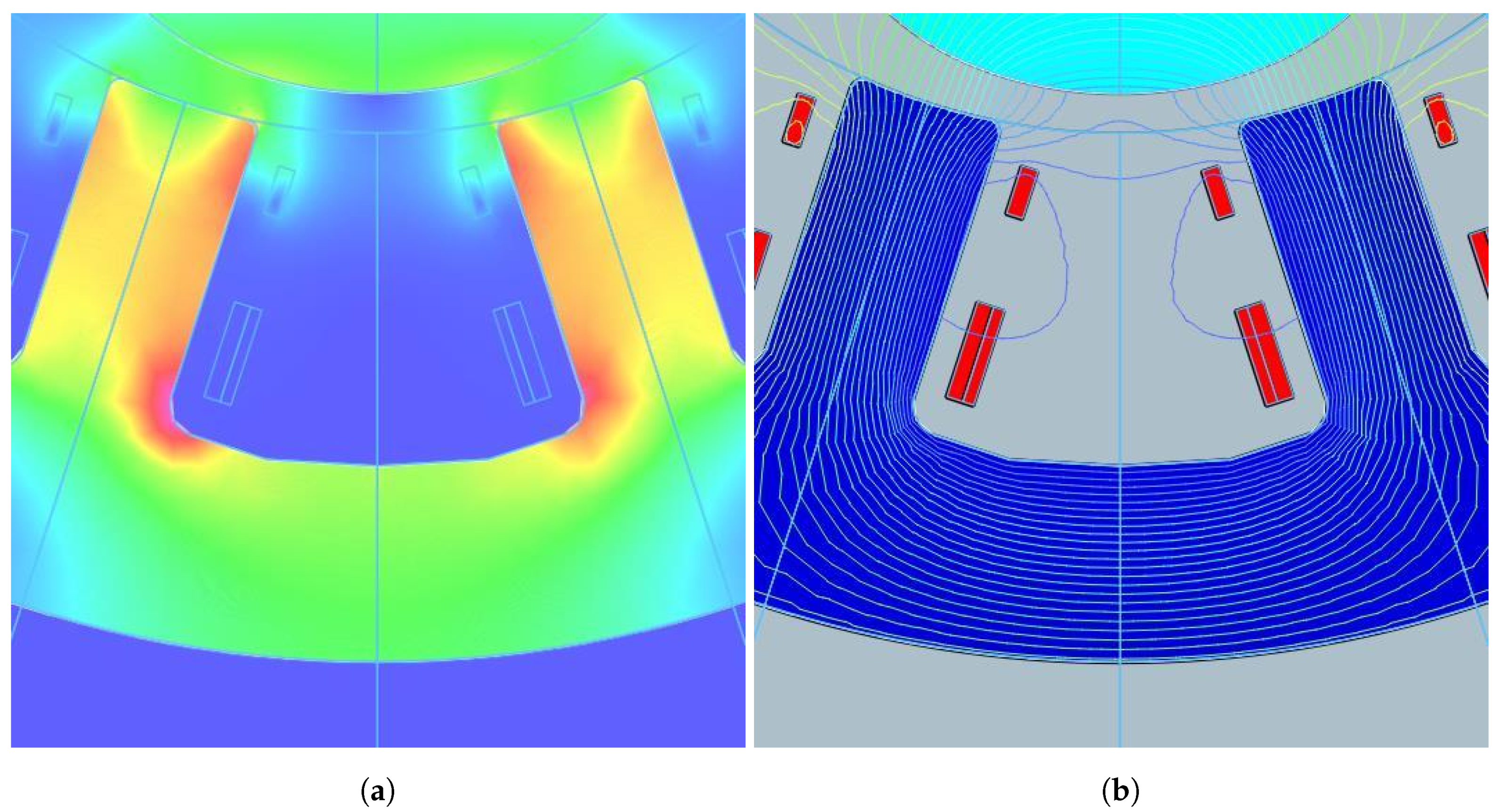
Figure 4.
Magnetic field distribution in SSPWMW-VRR. (a) Magnetic flux density distribution in the stator slots; (b) Magnetic field line distribution in the stator slots.
Figure 4.
Magnetic field distribution in SSPWMW-VRR. (a) Magnetic flux density distribution in the stator slots; (b) Magnetic field line distribution in the stator slots.
Figure 5.
Integrated Optimization Framework.
Figure 5.
Integrated Optimization Framework.
Figure 6.
Distribution of for different pole-pair and slot combinations.
Figure 6.
Distribution of for different pole-pair and slot combinations.
Figure 7.
Magnetic field distribution in the rotor at various positions.
Figure 7.
Magnetic field distribution in the rotor at various positions.
Figure 8.
SSPWMW-VRR simplified MEC
Figure 8.
SSPWMW-VRR simplified MEC
Figure 9.
SSPWMW-VRR magnetic equivalent circuit model inductive harmonic error.
Figure 9.
SSPWMW-VRR magnetic equivalent circuit model inductive harmonic error.
Figure 10.
Stator Slot Parameters: 1. , 2. , 3. , 4. , 5. , 6. .
Figure 10.
Stator Slot Parameters: 1. , 2. , 3. , 4. , 5. , 6. .
Figure 11.
Error distribution and parameter correlation analysis.
Figure 11.
Error distribution and parameter correlation analysis.
Figure 12.
Scatter plot matrix showing relationships between stator slot parameters.
Figure 12.
Scatter plot matrix showing relationships between stator slot parameters.
Figure 13.
Features Contribution from XGBoost Model.
Figure 13.
Features Contribution from XGBoost Model.
Figure 14.
Schematic diagram of the Multi-Layer Perceptron (MLP) architecture for stator slot shape optimization.
Figure 14.
Schematic diagram of the Multi-Layer Perceptron (MLP) architecture for stator slot shape optimization.
Figure 15.
FEA vs. Predicted Values with Error Bands.
Figure 15.
FEA vs. Predicted Values with Error Bands.
Figure 16.
Model Predictions vs. FEA Values: Offset Comparison.
Figure 16.
Model Predictions vs. FEA Values: Offset Comparison.
Figure 17.
Absolute Error Comparison: XGBoost vs. MLP.
Figure 17.
Absolute Error Comparison: XGBoost vs. MLP.
Figure 18.
High-precision low-speed dynamic test system for resolver.
Figure 18.
High-precision low-speed dynamic test system for resolver.
Figure 19.
Schematic of resolver test and analysis system
Figure 19.
Schematic of resolver test and analysis system
Figure 20.
Experimental output signal waveform.
Figure 20.
Experimental output signal waveform.
Figure 21.
Evaluation of VRRs: conventional vs. SSPWMW.
Figure 21.
Evaluation of VRRs: conventional vs. SSPWMW.
Figure 22.
Harmonic analysis of VRR prototypes.
Figure 22.
Harmonic analysis of VRR prototypes.
Table 2.
Stator Slot Parameter Ranges for Optimization
Table 2.
Stator Slot Parameter Ranges for Optimization
| Parameter |
Range (mm) |
Step Size (mm) |
| Slot width () |
1.0–5.0 |
0.5 |
| Jaw width () |
1.5–3.5 |
0.5 |
| Spacing between signal and excitation windings () |
0.5-1.5 |
0.5 |
| Spacing between excitation winding and stator ID () |
0.0-0.5 |
0.1 |
| Spacing between slot wedge and stator ID () |
0.0-1.2 |
0.4 |
| Slot wedge width () |
0.5–2.0 |
0.2 |
|
Disclaimer/Publisher’s Note: The statements, opinions and data contained in all publications are solely those of the individual author(s) and contributor(s) and not of MDPI and/or the editor(s). MDPI and/or the editor(s) disclaim responsibility for any injury to people or property resulting from any ideas, methods, instructions or products referred to in the content. |
© 2024 by the authors. Licensee MDPI, Basel, Switzerland. This article is an open access article distributed under the terms and conditions of the Creative Commons Attribution (CC BY) license (http://creativecommons.org/licenses/by/4.0/).
