1. Introduction
Recent technological evolution in metallurgy, in the design of concentrated solar panels associated with thermal energy storage and in nuclear engineering where molten salt reactors appear to be a promising issue [
1,
2,
3,
4,
5,
6], has increased the demand for efficient heat exchangers that can operate at very high temperatures. For high temperature operations, most of the fluids tend to evaporate or might need a huge amount of pressure to increase their boiling points. One method to overcome these challenges is the utilization of molten salts. Solid at room temperature, salts cannot transfer heat by convection and hence they need to be preheated above their melting point but kept under the boiling point in order to produce convective motion inside them. Due to their large thermal capacity and higher boiling points, molten salts are widely employed for thermal transfer at high temperature and in recent applications, they are used as electrolytes for energy storage systems such as liquid metal battery [
7,
8,
9,
10].
Salts are typically inorganic ionic mixture of fluorides, chlorides, carbonates,etc. Depending on the application, molten salts can be made of binary such as LiCl or ternary molecules such as NaCl-NaI. Due to their strong ionic bonds between the atoms a huge amount of heat is required to bring them to a liquid state. Hence, molten salts need to be maintained at high temperatures to keep them in a stable liquid state. Due to their low electrical and thermal conductivities, the application of an electrical current generates the Joule heating in the molten salts. This internal heating can trigger thermal convective motions in the molten salts and modify the heat transfer coefficient with their container.
Thermal convection induced by internal heating has been investigated by many authors [
11,
12,
13,
14,
15,
16,
17,
18,
19,
20] because this phenomenon is encountered in many engineering situations where internal heating can be induced by viscous heating or by dielectric heating or any other localized internal heat sources. It occurs also in Earth mantle where convective motions are sustained by radiogenic heating throughout the mantle itself and by the conduction from the underlying hot outer core due to internal radiation. In the upper atmosphere, thermal convection is driven by radiative cooling through and by heating from lower atmosphere and the Earth surface [
14]. In astrophysical context, nuclear burning processes occur in thin shells at some distance from the center of the star leading to compressible thermoconvective motions in the star [
17]. However, convection induced by internal heating has received much less attention than Rayleigh-Bénard convection induced by a constant temperature gradient imposed at the plates bounding the fluids [
21,
23].
The conduction state induced by internal heating has a parabolic temperature profile compared to the linear profile of the conduction state induced by fixed temperature difference. Linear stability analysis has been performed by different authors using different kinematic and thermal boundary conditions [
11,
12,
13,
17] to predict the threshold of thermal convection induced by internal heating. Numerical simulations have been performed to estimate the hydrodynamic field and the heat transfer coefficient associated with internal heating [
14,
15,
16]. Sparrow
et al.,
11] were the first to tackle the problem of thermal convection induced by an internal heating in a fluid between two parallel plates with different thermal boundary conditions, using semi-analytical method. They found that the threshold of thermal convection decreases with the magnitude of the internal heat source. The same problem was revisited by Kulaki
et al.,
12,
13] who performed a more exhaustive linear stability analysis and energetic analysis and obtained more accurate results on the critical parameters of thermal convection induced by internal heating. The implication of internal heating in astrophysical environment and in geophysics was developed by Strauss [
17] and by Goluskin
et al.,
14]. Another type of internal heating induced by a high-frequency electric field in dielectric liquids under microgravity conditions was investigated by Yoshikawa
et al.,
18] who showed also that the temperature of the conducting state has parabolic profile and determined the critical parameters for thermo-electro-convection induced by the dielectophoretic buoyancy force. Thermal convection induced by Joule-heating from magnetic fields has also been investigated in more complex flows systems such as generalized Couette flow of Jeffrey fluid [
19] or in a cylindrical annulus with different magnetic configurations [
20]. The estimate of convective flows and heat transfer induced by internal heating was performed in direct numerical simulations by Goluskin
et al.,
14,
16]. A recent work of Wang
et al. [
22] has developed unifying theory of scaling laws of turbulence in thermal convection induced by internal heating. All these studies have confirmed that, due to the parabolic temperature profile of the conduction state, thermal convection induced by internal heating appears for lower value of Rayleigh number compared to the threshold of Rayleigh-Bénard convection induced by an imposed constant temperature gradient.
In most of geophysical and astrophysical situations but also in technological applications, the magnetic field has a strong impact on the thermal convection in fluids. The effect of the magnetic field on Rayleigh-Bénard convection has been theoretically predicted by Chandrasekhar [
21] who showed the delay of the threshold of thermal convection in a liquid layer under magnetic field. This effect has been confirmed by further studies on higher regimes of thermoconvection [
24]. However, to our best knowledge, for internal heating induced convection in a horizontal liquid layer, the effect of the magnetic field has received less attention if any.
We have performed linear stability analysis to investigate the effect of magnetic field on the thermal convection induced by Joule heating in an electrolyte-type liquid crossed by a stationary homogeneous current for different kinematic and thermal boundary conditions. We have performed the energetic budget to identify the contribution of each force in the temporal evolution of the kinetic energy of perturbations close to the onset and we found that the Lorentz force acts as a dissipative force and delays the threshold ot thermal convection induced by internal heating. The paper is organized as follows. In
Section 2, we formulate the problem of thermal convection induced by Joule heating. The results of the linear stability are presented in
Section 3 and discussed in
Section 4. The last Section consists of the Conclusion.
2. Problem Formulation
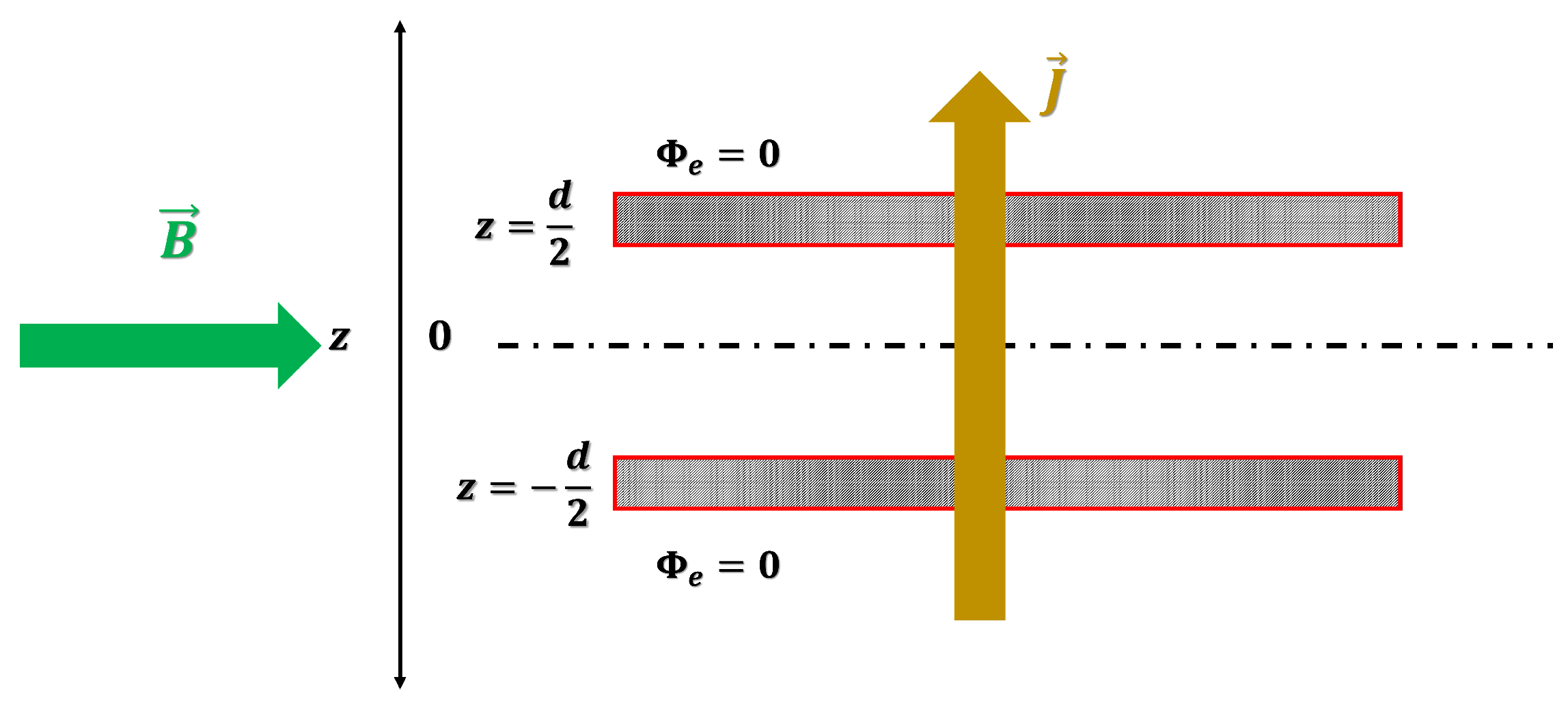
We consider a liquid layer of poor electrical and thermal conductivities, confined between two infinite horizontal plates located at
in cartesian coordinates system (
Figure 1). The liquid is considered as incompressible and Newtonian with the density
, the thermal expansion coefficient
, the kinematic viscosity
, the specific heat capacity
, the thermal conductivity
(where
is the thermal diffusivity) and the electrical conductivity
.
A uniform current
I of density
applied across the fluid layer (of cross-section area
S) generates a Joule heat in the liquid because of its weak electrical conductivity. The density
q of the Joule heat flux across the liquid layer is given by
2.1. Conduction State Induced by Internal Joule Heating
The stationary conduction state induced by Joule heating in a liquid layer confined between two horizontal infinite plates is characterized by the temperature profile
which satisfies the following heat equation
In order to allow the heat exchange with the environment, we impose the Robin boundary conditions which are hybrid thermal boundary conditions combining both the Neumann and the Dirichlet conditions at the plates:
where
h is the heat exchange coefficient which incorporates both the convective and radiative heat transfer and
is the temperature in the bulk of the environment away from the plates. Choosing
d and
as characteristic length and temperature respectively (i.e.
, the Joule heating yields the temperature scale
. The stationary heat equation and the Robin boundary conditions in dimensionless form become
where
is called Biot number. From now,
z is the dimensionless vertical coordinate. The conducting state induced by Joule heating in the liquid layer is thus described by a symmetric quadratic temperature profile
The maximum temperature
is reached at the mid-plane
of the liquid layer and it is very sensitive to the heat exchange coefficient i.e. to
[
13]. For isothermal boundary conditions (Neumann conditions) i.e. for
, we recover the temperature profile already obtained in previous studies [
13,
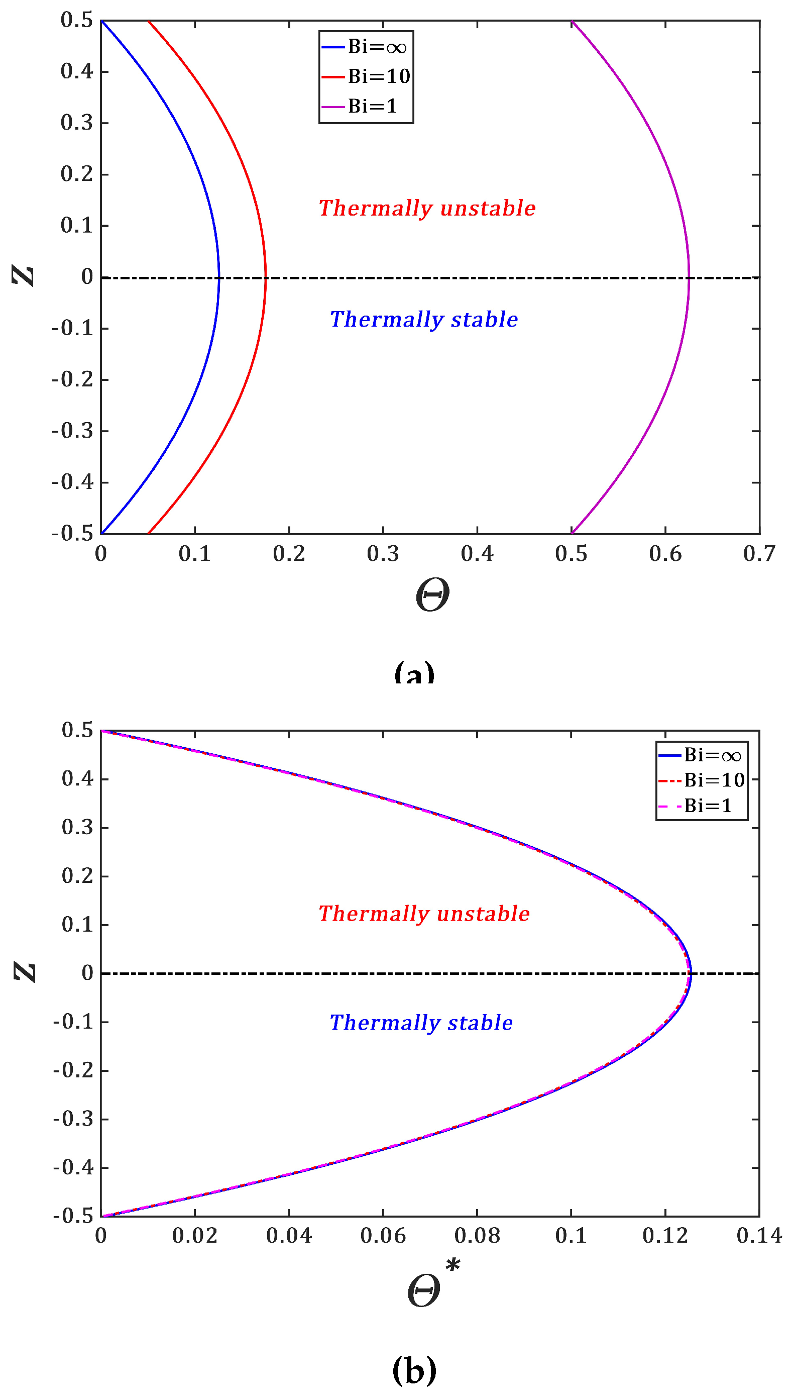
14]. The temperature profiles of the conducting state induced by the Joule heating are plotted in
Figure 2. They differ each other by the quantity
and they can be represented by a single curve
(
Figure 2b) defined as
The symmetry of the temperature profiles with respect to the mid-plane of the liquid layer is due to the symmetric boundary conditions where the heat exchange coefficients between the plates bounding the liquid with the bulk environment are assumed to be identical. If they are different, the symmetry of the conduction state is broken, and the temperature profiles are asymmetric with coefficients containing the Biot numbers
of each plate
l (
: lower plate,
: upper plate).
2.2. Driving Forces and Control Parameters
The internal Joule heating induces a temperature gradient and thus the Archimedean buoyancy
within the liquid layer where
is the liquid density at the reference temperature
. The lower layer of the liquid is thermally stable while the upper one is thermally unstable. We need to estimate the magnitude of the internal heating i.e. the magnitude of the applied current required to trigger thermal convection in the liquid layer. The Archimedean buoyancy will overcome the thermal diffusion and viscous dissipation if the Archimedean time scale
is much smaller than the combined visco-diffusive timescale
in the liquid. The Archimedean timescale for a buoyant liquid particle to rise the distance
is
. The timescales for viscous dissipation and thermal diffusion of the buoyant particle which rises the same distance
are
and
respectively. The temperature profile
in
Figure 2b yields
. Thus, the magnitude of the Archimedean buoyancy can be estimated by the Rayleigh number defined as follows
where
is the Prandtl number and
is the Grashof number sometimes called thermal Reynolds number if the characteristic thermal velocity of the buoyant particle under the action of Joule heating is introduced:
The second driving force in liquid layer crossed by an electric current density
and an applied horizontal magnetic field
is the Lorentz force density
. For weakly electrically conducting liquids
and for thermal convective velocities at laboratory scales
, the magnetic fields induced by the current density
and the drift Maxwell current
due to time variations of the electric field are so weak that they can be neglected in the so-called "quasi-static approximation" [
25]. Here
and
represent the magnetic permeability and the electrical permittivity of the liquid. The electric field
is thus stationary and it can be written as
where
is the electric potential chosen to vanish at the bounding plates at
(
Figure 1). The density current in the liquid is given by Ohm law
where
is the velocity induced in the liquid. The stationarity of the applied current density
leads to the Poisson equation relating the electric potential to the magnetic field :
In the quasi-stationary approximation [
25], the electric field in the conducting state is homogeneous and the electric potential satisfies the Laplace equation :
. This means that the electric field between the plates is homogeneous.
To estimate the magnitude of the Lorentz force acting in the liquid, we introduce the Hartmann number
which is the ratio of the magnitude
of applied magnetic field to the intrinsic magnetic field of the liquid
The Hartmann number is often defined as the ratio between the characteristic length of the flow
d and the Hartmann length
i.e.
The quantity
is called the Chandrasekhar number.
To make the governing equations dimensionless, we use the liquid layer thickness
d as the characteristic scale for space coordinates and the viscous diffusion velocity
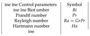
as a characterstic velocity. The dynamics of the liquid subject to Joule heating can be uniquely determined by four independent dimensionless control parameters given in
Table 1. The Biot number
characterizes the heat exchange between the liquid and its environment, the Prandtl number
determines the thermo-viscous diffusive nature of the liquid, the Rayleigh number
measures the magnitude of the Archimedean buoyancy compared to the viscous dissipation and thermal diffusion, the Hartmann number
is the ratio between the Lorentz force and the viscous dissipation. The Grashoff number
is not an independent control parameter, it is sometimes used instead of
.
2.3. Linearized Equations for Internal Heating-Driven Convection
We superimpose to the conduction state small perturbations of the temperature field
, of the electric potential
, of the generalized pressure
and the velocity
. We assume the validity of the Boussinesq approximation. Linearization of the momentum, energy and electric potential equations near the base state yields the following equations in non-dimensional form [
7,
25]:
The second term in Equation (14b) is due to the viscous dissipation, the third term is the Archimedean buoyancy and the last term represents the Lorentz force. The temperature field is coupled to the velocity field via Equations (14b) and (14c). In the quasi-stationary approximation, the pertubation
of the magnetic field is neglected [
25].
Two different kinematic boundary conditions are imposed on the fluid i.e. the no-slip boundary condition where the velocity perturbations vanish at the walls and free-slip boundary condition where the normal stress are vanishing at the walls. The free-slip boundary conditions read
The no-slip boundary conditions are
The thermal boundary conditions stem from boundary conditions (3):
2.4. Normal Mode Expansion and Numerical Method
In the present study, we choose the horizontal axes in such a way that the magnetic field is applied along the horizontal axis
and its non-dimensional form is
. The infinitesimal perturbations
are expanded as normal modes
where
is the structure function of the perturbations, the quantity
is complex temporal growth rate with
and
being the real growth rate and the frequency of the perturbations respectively. As the system is assumed infinite in the horizontal plane, the wave numbers
and
are real. Substitution into the linearized Equation (14) yields the following system of equations of the complex amplitudes
:
with the operators
. The boundary conditions develops into,
The system of equations (14) can be written in a matrix form as follows :
where the expressions of the matrices
and
can easily be derived from the system of Equation (19). The system of Equation (21) is an eigenvalue problem with the eigenvalue
s and the structure function of the perturbations
is the eigenvector. The eigenvalue
s is searched as function of the control parameters and of the wave numbers of the perturbations
We are interested in the determination of the threshold of thermal convection, so we look for marginal perturbations for which
. The marginal state are thus represented by the hypersurface
. We fix
and
and the hypersurface is reduced to a marginal stability curve
where
.
In order to determine the marginal stability curve, we use the following numerical scheeme. The system of equations of complex amplitudes (19) and the boundary conditions (20) are discretized using the Chebyshev spectral method. The Chebyshev variable
is related to the vertical coordinate
z as follows,
where
. Discretization is done along vertical direction
corresponding to collocation points
. The highest order of Chebyshev polynomials needed to ensure the convergence is set to
.
Marginal stability curves for which are plotted in the plane and their lowest minimum determines the critical parameters of thermal convection.
3. Results
In the absence of the magnetic field, the critical modes are invariant with respect to rotation of the wavenumber vector in the plane : the critical patterns can either be rolls , square patterns() or hexagonal patterns (). the Lorentz force due to magnetic field breaks this invariance. Here we have assumed that the perturbations are two-dimensional i.e. , so that we have . We first present results the threshold and critical wavenumber of thermal convection for different values of and the eigenfunctions in the absence of the magnetic field, and then we analyze the effect of the magnetic field (i.e. of ) on the critical parameters of the convection induced by Joule heating.
3.1. Threshold of Internal Heating-Induced Convection
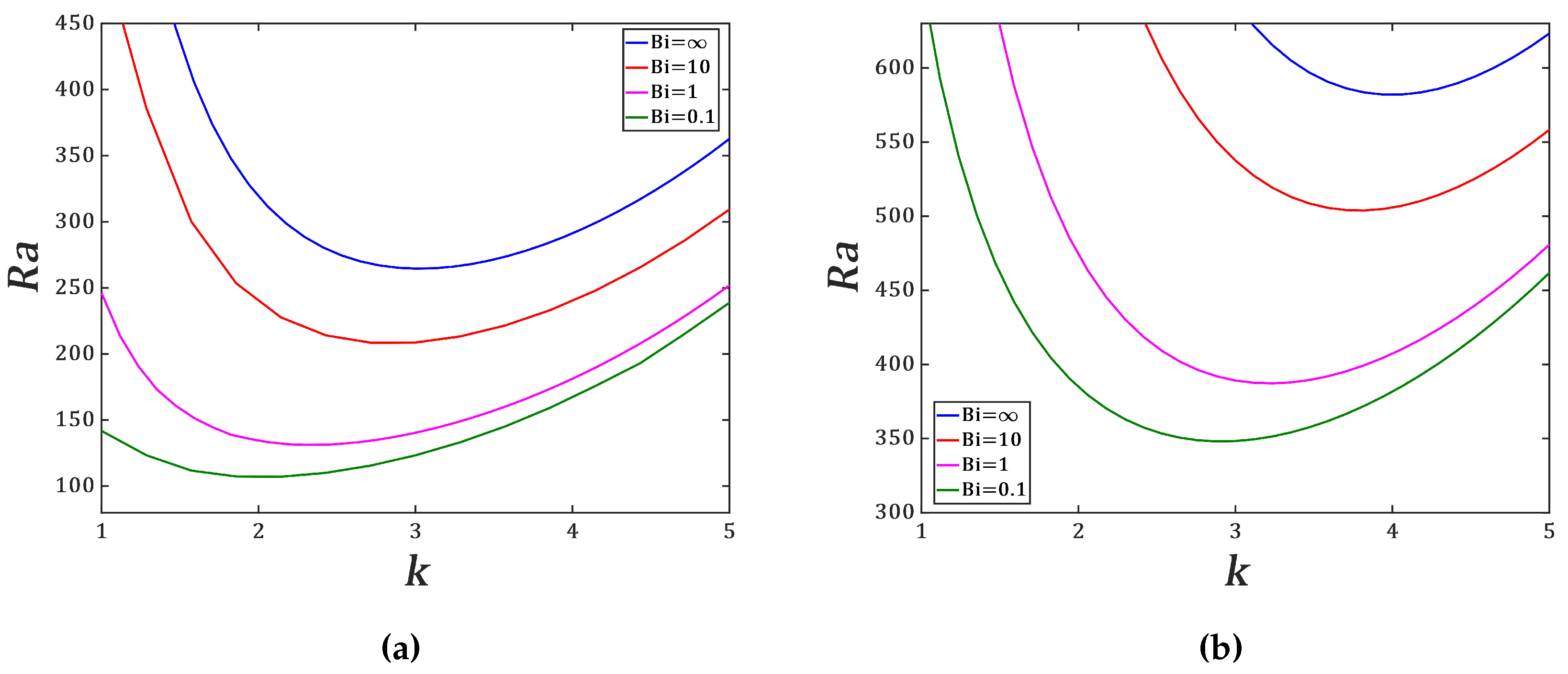
We have computed the marginal stability curves for free-slip and no-slip boundary conditions and for different values of Biot number
(
Figure 3). The critical modes are stationary i.e.
and they are independent of
. The threshold of Joule heating-induced convection between two horizontal plates is lower than the one of the classic Rayleigh-Bénard convection with a constant temperature gradient between the plates. This is due to the quadratic profile of the temperature field of the conduction state. We recover the results of previous studies [
11,
12,
13,
17].
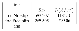
Table 2 presents the critical parameters
for chosen values of
. For
corresponding to isothermal boundary conditions, the threshold is the highest for both types of kinematic boundary conditions. This suggests that the heat exchange between the liquid layer and the environment favors the occurrence of Joule heating-induced convection. The effect of the Biot number on the size of thermoconvective cells induced by internal heating is significant : thermoconvective cells have small size for isothermal boundary conditions than in the presence of the heat exchange with the environment. For a fixed value of
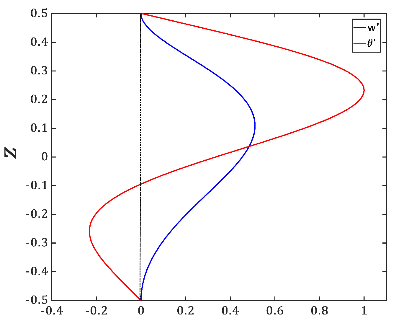
, we recover the result that the free-slip conditions favor the convection as in the case of the classic Rayleigh-Bénard convection. In
Figure 4, we have plotted the vertical profiles of the temperature perturbation
and of the vertical velocity component
.
The vertical profile of the temperature
and of the vertical velocity component
in
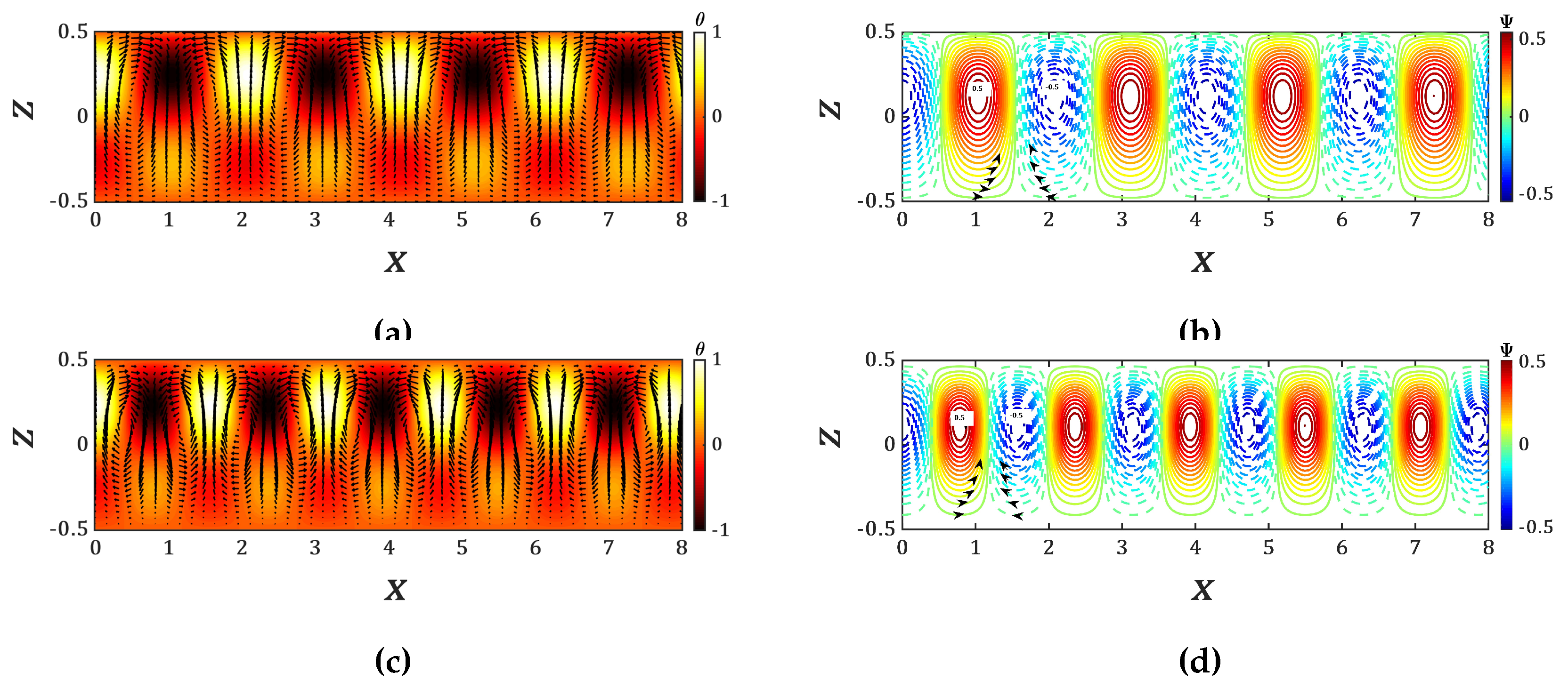
Figure 4 show that the temperature and velocity perturbations perturbations penetrate into the lower stable part of the liquid. However, the upper part of the liquid layer is more active than the lower part as the last one is thermally stable. The eigenfunctions of the temperature field to which we have superimposed the velocity vectors and the stream functions
of the critical states are plotted in
Figure 5. The core of the stream functions are also located in the thermally unstable zone of the liquid layer.
3.2. Effect of the Magnetic Field on Internal Heating Induced Convection
Different studies on thermal convection have shown that the vertical magnetic field delays the occurrence of the Rayleigh-Bénard convection with a decrease in cell size [
21]. In the present study, we analyze the effect of the horizontal dimensionless magnetic field
on the threshold of internal heating-driven convection. We have solved the eigenvalue problem for different values of the Hartmann number
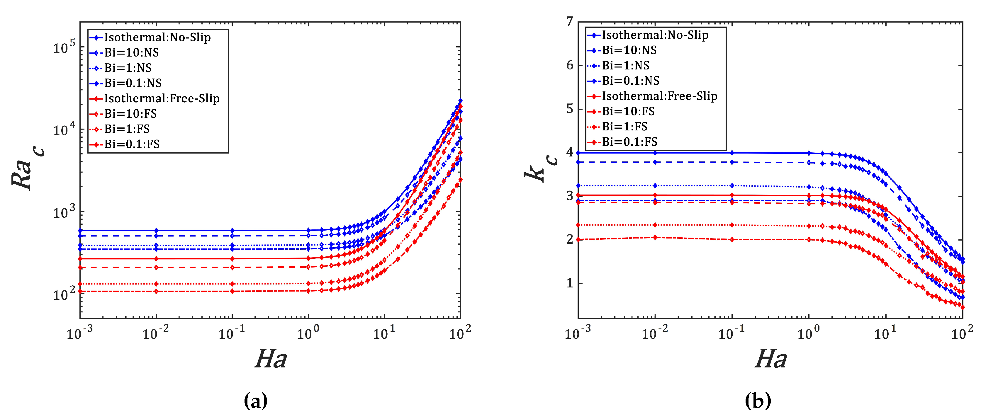
and plotted in
Figure 6 the critical parameters
as functions of
. The critical modes are stationary for all values of
and the threshold is independent of
. The effect of the magnetic field on the threshold of thermal convection induced by Joule heating becomes significant for
where the threshold
and the critical wavelength
start to increase for all values of Biot number
. For both types of kinematic boundary conditions with imposed isothermal boundaries, the variations
can be approximated by quadratic polynomials. For free-slip boundary conditions,
For no-slip boundary condition,
The stabilization effect of the magnetic field on thermal convection becomes significant when the applied field
becomes larger than the characteristic intrinsic magnetic field
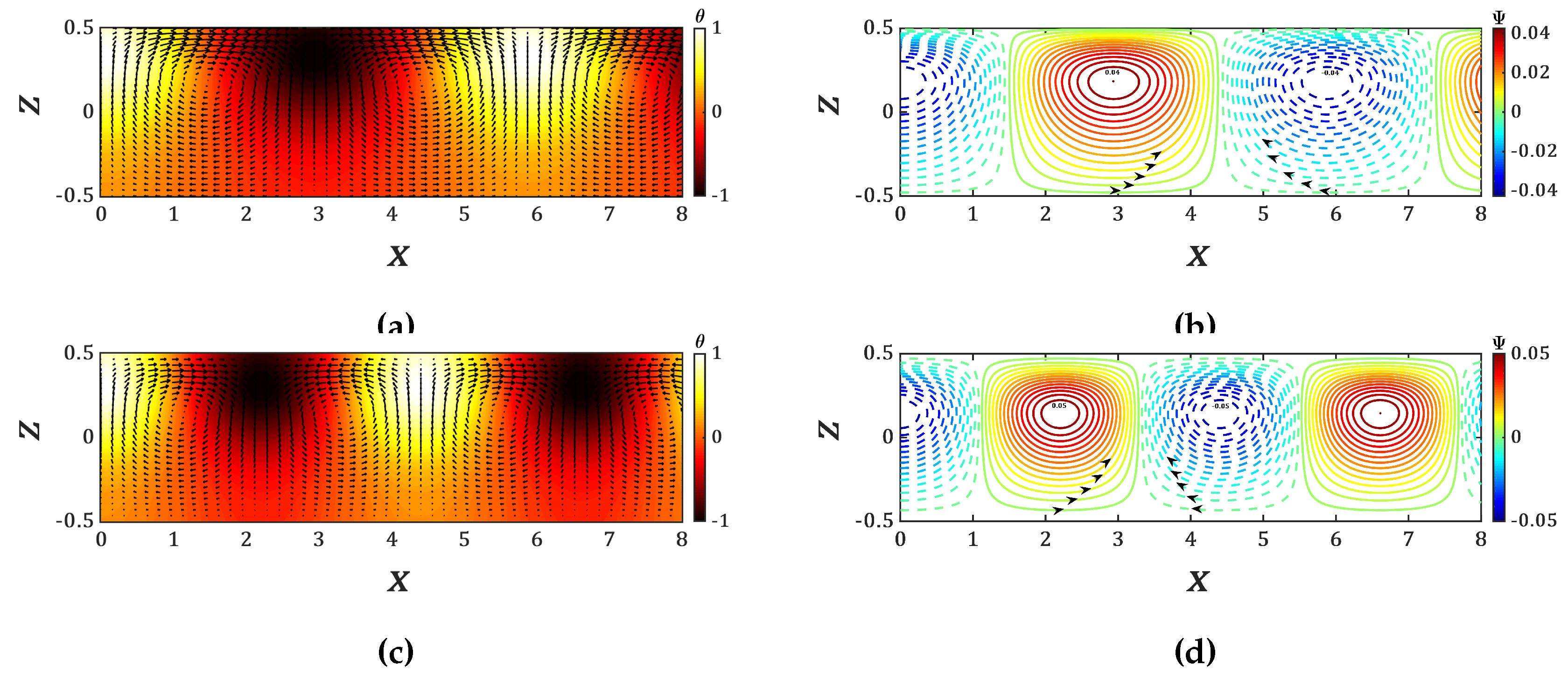
which depends on the properties and of the thickness of the liquid according to the relation (12). The isotherms and stream functions of the critical modes for
are plotted in
Figure 7. They illustrate the increase of wavelength of the thermoconvective cells compared to the case without the magnetic field shown in
Figure 5.
4. Discussion
We have revisited the linear stability of thermal convection induced by Joule heating in a liquid layer crossed by a homogeneous current of intensity
I and bounded by two infinite horizontal plates which exchange heat with the environment. We have confirmed results from previous studies [
11,
12,
13,
17] which have shown that the heat exchange between the liquid and the environment favors the appearance of thermal convection by the energy input into the liquid.
We have neglected the induced currents and magnetic fields in the liquid. The applied horizontal magnetic field delays the occurrence of thermal convection as in the case of Rayleigh-Bénard convection. In order to explain this result, we have derived from the system of Equation (14), the equation of the energy budget of the perturbations
where
is the kinetic energy,
is the power of the Archimedean buoyancy,
[
26] is the dissipation due to viscosity and
is the power performed by the Lorentz force in which we have neglected the power produced by the perturbation of the electric field. The Lorentz force contributes to the dissipation of the kinetic energy of the perturbations and thus, it delays the thermal convection.
Molten salts are used in some microfluidic systems used in aeronautics and in electronic circuiteries [
28]. Molten salts have found a new application in the design of the liquid metal batteries which consist of three superimposed liquid layers where an electrolyte is sandwiched between two liquid metals serving as electrodes [
10,
27]. These liquid layers are crossed by an electric current which induces a Joule heating in the electrolyte because of its low electrical conductivity compared to the liquid metals. To control the thermoconvective motion in the liquid metal batteries where this motion can induce short-circuit and then damage the battery, the application of the magnetic filed in appropriate direction seems to be a solution to suppress or delay the thermoconvective motion in the battery.
From the critical values
, one can estimate the critical current
required to trigger thermal convection induced by Joule heating in a liquid layer of thickness
d using the relation (7) between the control parameter
and the applied current
J:
Table 3 yields the values of the critical current
for a thickness
of the
molten salt with properties [
7] :
,
,
,
,
.
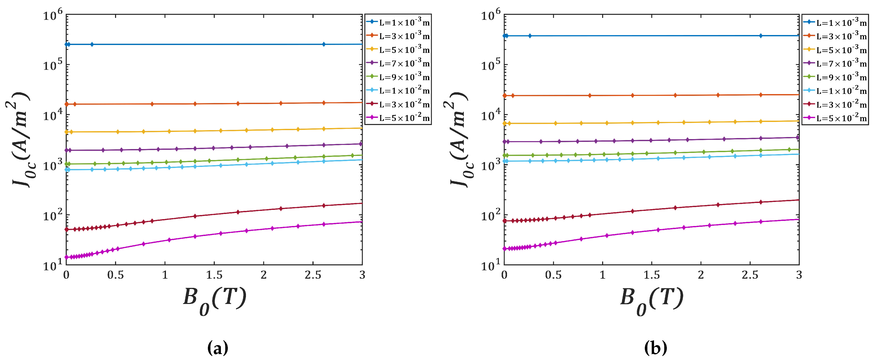
Figure 8 shows the variation of critical current density
that has to be applied to avoid convective motions as a function of applied magnetic field
. These calculations have been made for different thickness of molten salt layer.
5. Conclusions
Thermal convection induced in a liquid layer confined between two infinite horizontal plates and subject to Joule heating by a homogeneous current has been revisited for different kinematic and thermal boundary conditions. The application of the horizontal magnetic field leads to the delay of thermal convection and to the increase of wavelength of the thermoconvective cells. The energy budget shows that the Lorentz force produces a negative power and so it contributes, together with viscous forces, to the dissipation of the kinetic energy of thermoconvective perturbations induced by Joule heating in the liquid layer.
Acknowledgments
The authors acknowledge the financial support of the French National Research Agency (ANR) through the Program Investissements d’Avenir (Grant ANR-10 LABX-09-01, LabEx EMC3/project HILIMBA) and Région Normandie (Réseau d’Intérêt Normand - Label d’Excellence).
References
- Kuchibhotla, A.; Banerjee, D.; Dhir, V. Forced convection heat transfer of molten Salts: A review. Nucl. Eng. Des. 2020, 362, 110591. [Google Scholar] [CrossRef]
- Jeong, Y.S.; Seo, S.B.; Bang, I.C. Natural convection heat transfer characteristics of molten salt with internal heat generation. J. Therm. Sci 2018, 129, 181–192. [Google Scholar] [CrossRef]
- Zhang, S.; Sun, X.; Domniguez-Ontiveros, E.E. Numerical study on convective heat transfer and friction characteristics of molten salts in circular tubes. Ann. Nucl. Energy 2020, 142, 107375. [Google Scholar] [CrossRef]
- Fiorina, C.; Cammi, A.; Luzzi, L.; Mikityuk, K.; Ninokata, H.; Ricotti, M.E. Thermal-hydraulics of internally heated molten salts and application to the Molten Salt Fast Reactor. J. Phys. Conf. Ser. 2014, 501, 012030. [Google Scholar] [CrossRef]
- Nunes, V.M.B.; Queirós, C.S.; Lourenço, M.J.V.; Santos, F.J.V.; castro, C.A.N.D. Molten salts as engineering fluids–A review: Part I. Molten alkali nitrates. Appl. Energy 2016, 183, 603–611. [Google Scholar] [CrossRef]
- Turchi, C.S.; Vidal, J.; Bauer, M. Molten salt power towers operating at 600–650 C: Salt selection and cost benefits. Sol. Energy 2018, 164, 38–46. [Google Scholar] [CrossRef]
- Shen, Y.; Zikanov, O. Thermal convection in a liquid metal battery. Theor. Comput. Fluid Dyn. 2016, 30, 275–294. [Google Scholar] [CrossRef]
- Köllner, T.; Boeck, T.; Schumacher, J. Thermal Rayleigh-Marangoni convection in a three-layer liquid-metal-battery model. Phys. Rev. E 2017, 95, 053114. [Google Scholar] [CrossRef]
- Personnettaz, P.; Beckstein, P.; Landgraf, S.; Köllner, T.; Nimtz, M.; Weber, N.; Weier, T. Thermally driven convection in Li||Bi liquid metal batteries. J. Power Sources 2018, 401, 362–374. [Google Scholar] [CrossRef]
- Kelley, D.H.; Weier, T. Fluid Mechanics of Liquid Metal Batteries. Appl.Mech. Rev. 2018, 70, 020801. [Google Scholar] [CrossRef]
- Sparrow, E.M.; Goldstein, R.J.; Jonsson, V. Thermal instability in a horizontal fluid layer: effect of boundary conditions and non-linear temperature profile. J. Fluid Mech. 1964, 18, 513–528. [Google Scholar] [CrossRef]
- Kulacki, F.A.; Goldstein, R.J. Thermal convection in a horizontal fluid layer with uniform volumetric energy sources. J. Fluid Mech. 1972, 55, 271–287. [Google Scholar] [CrossRef]
- Kulacki, F.A.; Goldstein, R.J. Hydrodynamic instability in fluid layers with uniform volumetric energy sources. Appl. Sci. Res. 1975, 31, 81–109. [Google Scholar] [CrossRef]
- Goluskin, D.; Spiegel, E.A. Convection driven by internal heating. Phys. Lett. A 2012, 377, 83–92. [Google Scholar] [CrossRef]
- Goluskin, D. Internally heated convection beneath a poor conductor. J. Fluid Mech. 2015, 771, 36–56. [Google Scholar] [CrossRef]
- Goluskin, D.; der Poel, E.P.V. Penetrative internally heated convection in two and three dimensions. J. Fluid Mech. 2016, 791, R6. [Google Scholar] [CrossRef]
- Strauss, J.M. Penetrative convection in a layer of fluid heated from within. Astrophys. J. 1976, 209, 179–189. [Google Scholar] [CrossRef]
- Yoshikawa, H.N.; Kang, C.; Mutabazi, I.; Zaussinger, F.; Haun, P.; Egbers, C. Thermoelectrohydrodynamic convection in parallel plate capacitors under dielectric heating conditions. Phys. Rev. Fluids 2020, 5, 113503. [Google Scholar] [CrossRef]
- Mng’ang’a, J.; Onyango, E.R.; Chilingo, K.J. Joule heating and induced magnetic field on magnetohydrodynamic generalized Couette flow of Jeffrey fluid in an inclinded channel with Soret and Dufour effects. International Journal of Ambient Energy 2024, 45, 2305328. [Google Scholar] [CrossRef]
- Muhammad, M.Y.; Lawan, M.A.; Gambo, Y.Y. Heat absorption effect of magneto-natural convection flow in a vertical concentric annulus with influence of radial and induced magnetic field. Scientific Reports 2024, 14, 15165. [Google Scholar]
- Chandrasekhar, S. Hydrodynamic and hydromagnetic stability; Oxford University Press: Oxford, UK, 1961. [Google Scholar]
- Wang, Q.; Lohse, D.; Shishkina, O. Scaling in internally heated convection: A unifying theory. Geophys. Res. Lett. 2020, 10, 1029. [Google Scholar] [CrossRef]
- Mutabazi, I.; Wesfreid, J.E.; Guyon, E. Dynamics of spatio-temporal cellular structures: Henri Bénard centenary review; Springer: Berlin/Heidelberg, Germany, 2006. [Google Scholar]
- Aurnou, J.M.; Olson, P.L. Experiments on Rayleigh–Bénard convection, magnetoconvection and rotating magnetoconvection in liquid gallium. J. Fluid Mech. 2001, 430, 283–307. [Google Scholar] [CrossRef]
- Davidson, P.A. An introduction to magnetohydrodynamics; Cambridge University Press: Cambridge, UK, 2001. [Google Scholar]
- Eckhardt, B.; Grossmann, S.; Lohse, D. Torque scaling in turbulent Taylor–Couette flow between independently rotating cylinders. J. Fluid Mech. 2007, 581, 221–250. [Google Scholar] [CrossRef]
- Kim, H.; Boysen, D.A.; Newhouse, J.M.; Spatocco, B.L.; Chung, B.; Burke, P.J.; Bradwell, D.J.; Jiang, K.; Tomaszowska, A.A.; Wang, K.; Wei, W.; Ortiz, L.A.; Barriga, S.A.; Poiseau, S.M.; Sadoway, D.R. Liquid Metal Batteries : Past, Present, and Future. Chem. Rev. 2013, 113, 2075–2099. [Google Scholar] [CrossRef] [PubMed]
- Caraballo, A.; Galán-Casado, S.; Caballero, A.; Serena, S. Molten salts for sensible thermal energy storage: A review and an energy performance analysis. Energies 2021, 14, 1197. [Google Scholar] [CrossRef]
|
Disclaimer/Publisher’s Note: The statements, opinions and data contained in all publications are solely those of the individual author(s) and contributor(s) and not of MDPI and/or the editor(s). MDPI and/or the editor(s) disclaim responsibility for any injury to people or property resulting from any ideas, methods, instructions or products referred to in the content. |
© 2024 by the authors. Licensee MDPI, Basel, Switzerland. This article is an open access article distributed under the terms and conditions of the Creative Commons Attribution (CC BY) license (http://creativecommons.org/licenses/by/4.0/).


