1. Introduction
In engineering, as in other fields of study, teaching processes are in a state of constant evolution, with the result that new challenges arise that must be met if quality education is to be provided in accordance with the particular context in which it is being delivered. With the advent of new technologies, educational environments have undergone a significant transformation in the digital era. This evolution can be traced back to the Gutenberg printing press, which emerged in 1450 as a revolutionary tool for the dissemination of knowledge on a mass scale [
1]. In the context of academia, the advent of the digital era is largely associated with the rise of Information and Communication Technologies (ICT). Initially, ICT facilitated the creation of innovative tools for the advancement and accessibility of educational materials, improving pedagogical processes. Subsequently, the emergence of web-based platforms paved the way for the advancement of educational technologies and interaction tools. These developments promoted collaborative learning, multiple intelligences, and the integration of mobile devices, ultimately improving students' comprehension and knowledge retention [
1,
2,
3]. Another significant aspect of contemporary higher education is the implementation of learning management systems (LMS) in virtual and distance learning environments. These systems leverage information and communication technology (ICT) tools to personalize learning processes, thus improving student motivation [
4]. The advent of artificial intelligence (AI) has marked a significant evolution in the field of Learning Management Systems (LMS), particularly in higher education institutions. AI not only improves the capabilities of existing digital tools, but also introduces novel features such as adaptive learning systems, research support tools, and autonomous or assisted teaching mechanisms, thus personalizing the learning journey and aligning it with the individual needs of each learner [
5].
The training processes of an engineer in area of automation and control should be oriented not only to the handling of technological tools, time management, and collaborative work, but also to the promotion of a permanent contact with the challenges that take place in society and industry. Therefore, it is essential to define the value of academic work in automation and control processes, which should assist students in developing other fundamental skills, including those related to analog circuits, digital electronics, the analysis of dynamic systems, an introduction to control, and other activities that require precision and robustness [
6]. To enhance the rigor of academic work, it is essential to reinforce the fundamental domains of engineering, while also establishing laboratories equipped with test plants that mirror authentic industrial processes. This will facilitate the integration of diverse scenarios beyond the academic domain. Test plants have emerged as a pivotal area of interest in recent years, driven by two key factors. The first emphasizes the importance of automation and process control within organizations and the need for academia to align with these developments [
7].
The second factor is the high cost of laboratory equipment, as seen in the offerings of industry-leading companies such as Festo and Mitsubishi. Consequently, a significant number of academic institutions have chosen to create low-cost, modular, and scalable test prototypes with the intention of integrating them into their engineering education processes. As an example, [
8] proposed applications for digital robot manipulation and control in an educational environment were proposed. In [
9], a control system for a flying shear servo motor was designed using universal controllers. This is a significant contribution to the field as it allows for operation without restriction to a particular manufacturer. The work presented in [
10] details the development of a three-dimensional model for a flying shear, with a particular focus on the structural and dynamic analysis of the shear process.
In [
11] the mechanism for a sheet shearing plant was designed with an analytical focus on the losses generated in the transformer cores due to irregular shearing. These works represent some of the developments in the modeling of shear systems carried out in universities and institutes. Most of these are at the simulation level. Another area of focus in prototype development at the academic level has been the integration of hardware development, in which devices are manipulated or controlled from remote applications, in addition to the use of simulation. In [
12] a remote laboratory was conducted for two test plants (an industrial robot and a mobile robot) using Java Servlet environments. In [
13], an investigation was conducted into the implementation of a real-time control system for a 20 KVA power converter using the Texas Instruments LAUNCH-XL F28379D board. This research underscores the importance of employing dedicated hardware in control systems. Additional studies emphasize the value of using laboratory plants that mimic authentic industrial processes in an academic context. In [
14], the authors underscored the importance of the evolution of the pedagogical methodology and developed a state-space control system in a float-shield laboratory plant to replicate authentic environments in the classroom setting.
As evidenced in the reviewed literature, research on fly shear prototypes has focused primarily on simulations of estimated mathematical models. The methodology utilized in this research makes a significant contribution to the field, as it involves the design and simulation of the cut-to-flight plant, which takes into account real-world behavior. This allows our work to be replicable and the presented prototype to be fully implementable in academic settings. Another contribution of this work to engineering is its integration of concepts from control theory, mechanical engineering, and physical principles. This integration allows for a detailed understanding of the operation of the proposed fly cutting plant, facilitating interdisciplinary research in new areas. This research contributes to the field of electronic engineering by integrating the industrial sector in the search for efficient solutions to improve processes involving the use of new technologies, such as augmented reality laboratories and 3D printing. These technologies facilitate the testing of designed prototypes prior to their final implementation.
This research presents the design and simulation of a flying cutting plant for the implementation of real-time control strategies in academic environments. The plant design was conducted using a three-dimensional modeling approach, which allowed the creation of a digital prototype that could be subsequently implemented. The operational efficacy of the fly-cutting plant was validated through real-time simulations; accordingly, the plant was represented in mathematical terms. This work makes additional contributions to the automation and control area within the Electronic Engineering Program at Universidad del Quindío, including, for instance:
A laboratory plant was designed to emulate the process of continuous cutting of moving parts, a process that is frequently performed in various industrial sectors.
The aim was to define the requirements and mechanisms necessary to implement a flying cutting plant on a laboratory scale.
The development of applications using specialized tools for the design and simulation of real-time control systems is oriented toward the modeling and control of industrial processes at the laboratory scale. This contrasts to previous work, such as that presented in [
15], which focused on robot manipulation.
The paper is structured into distinct sections. Initially, the methodology (including materials and methods) employed for the design and simulation of the fly cutting plant is outlined. Subsequently, the results obtained and their analysis in relation to a control strategy implemented are presented. Finally, a comprehensive summary of the main conclusions derived from the research conducted will be provided.
2. Materials and Methods
2.1. Materials
2.1.1. Flying Cutting Prototype
Flying cutting plants or machines (also known as flying shears) are mechanical systems that carry a cutting blade and a conveyor belt to transport the material to be processed. These devices can operate in mechanical synchronism between the cutting blade and the moving material or by matching their speeds with the assistance of additional electronic devices. Different manufacturers, such as RISHBIN, produce various types of flying cutting machines. RISHBIN's catalog includes metal plates classified by cutting type: rotary, crank-rotary lever, eccentric crank, and pendulum plants [
16]. An illustrative example is provided in [
17], in which a crank-type cutting machine is used for the kinematic analysis of length, profile error, acceleration, and velocities in different cutting phases. Schneider Electric presents an alternative classification system for RISHBIN flying shears. The industry classifies its shear systems into T1, T2, or T3 types [
18].
Figure 1 illustrates the T1 flying shearing plant, which comprises a cutting system in which the base of the saw serves as a support for the material and is synchronized at the same speed as the material while the saw performs the cut.
2.1.2. MATLAB PID Tuner
MATLAB (Matrix Laboratory) is a numerical computational tool that integrates tools for calculation, visualization, and programming in an interactive environment. It allows users to express solutions to problems in a form similar to mathematical notation, with arrays serving as the fundamental data structure because they do not require dimensioning. All data are represented with double precision, facilitating more accurate calculations and more convenient interaction [
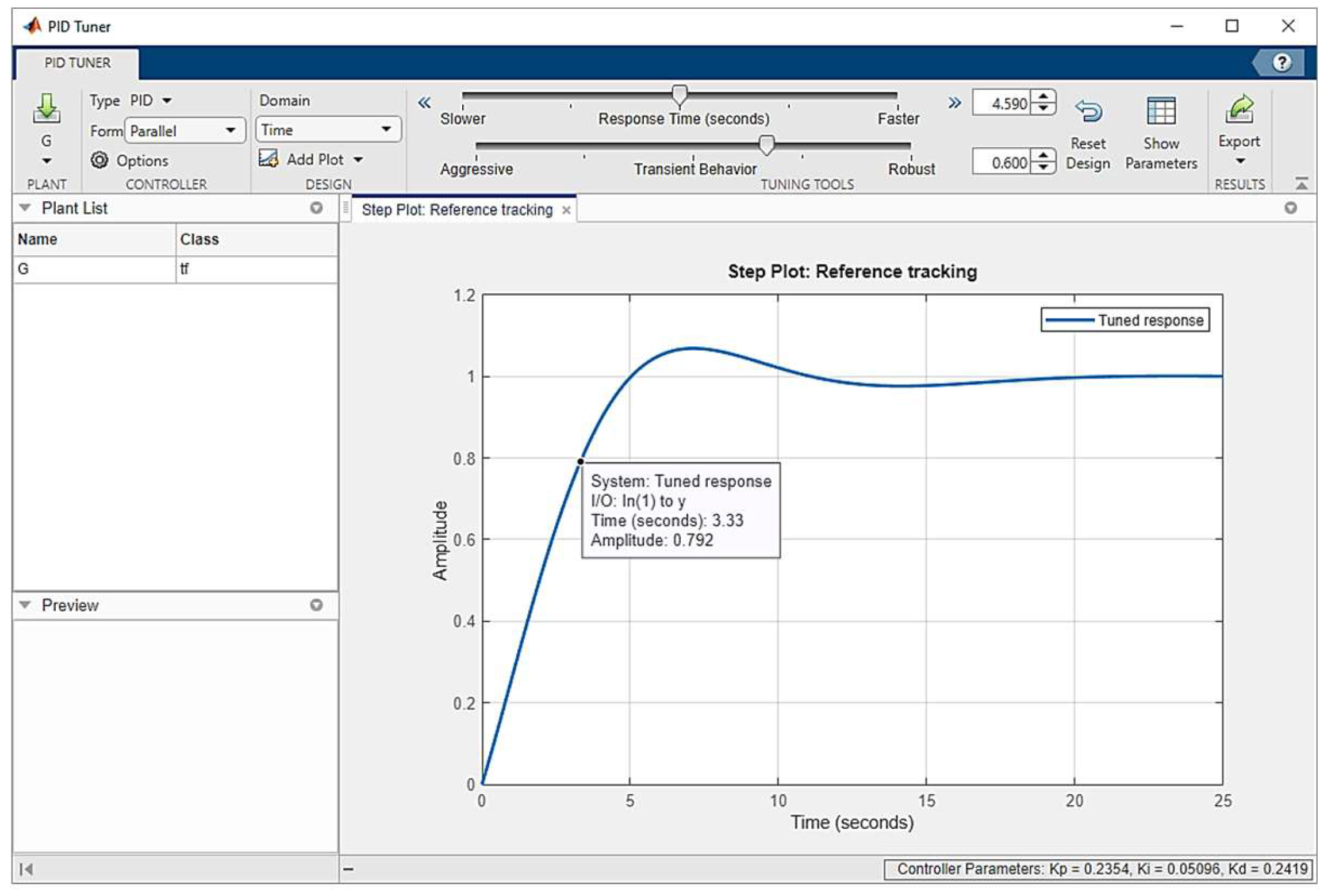
19]. MATLAB offers a variety of toolboxes that provide a comprehensive set of specialized functions for diverse areas of knowledge. The Control Toolbox offers the PID Tuner application, which enables automated adjustment of the gains associated with designed controllers. The design process is graphical, allowing the examination of controller performance and robustness through the analysis of the associated graphical representations. A notable aspect of PID Tuner is its ability to facilitate the design of controllers in the time and frequency domain.
Figure 2 illustrates the user interface of the MATLAB PID Tuner application [
20].
2.1.3. SketchUp 3D Design
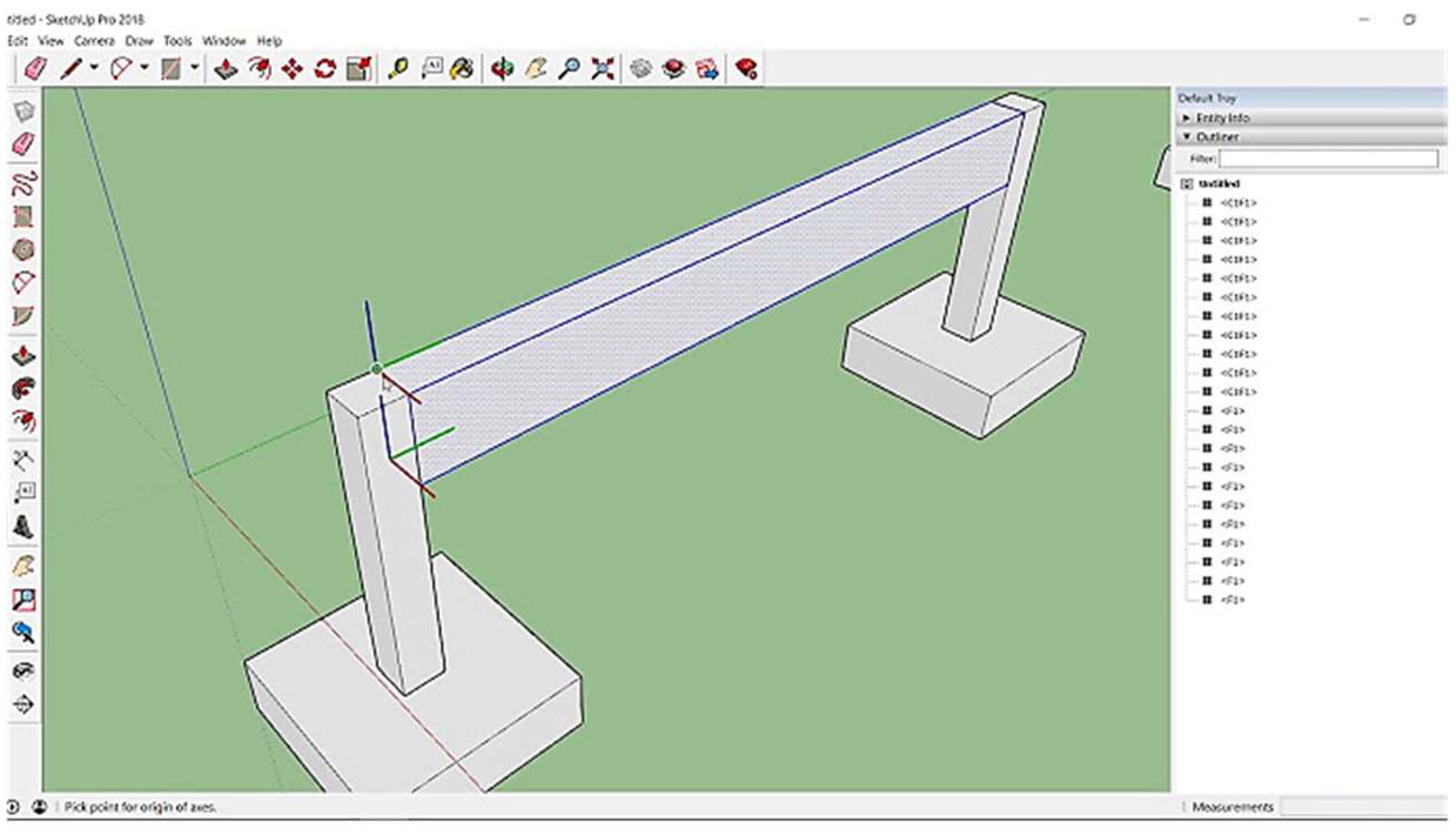
SketchUp is a versatile 3D modeling tool that enables the creation of three-dimensional designs and models, as well as extended reality experiences. It is available on multiple platforms, including desktop, web, and mobile versions, making it an ideal choice for professionals in a variety of disciplines, especially in the engineering field. One of its most outstanding features is the integration of artificial intelligence (AI) functionalities, which optimize and accelerate workflows, facilitating the design process. The graphical user interface of SketchUp in its desktop version is illustrated in
Figure 3.
2.2. Methods
2.2.1. Plant Structure
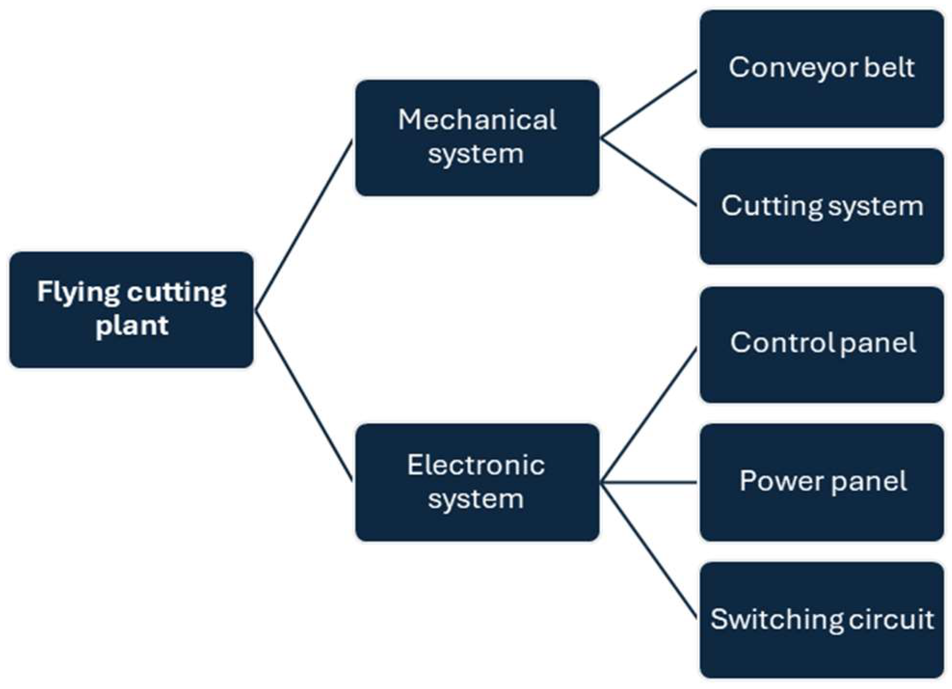
The structure of the designed flying cutting plant is illustrated in
Figure 4. The block diagram shown is made up of two principal systems. The first system corresponds to a mechanical component that includes a conveyor belt and a cutting system with three-dimensional movement along the X, Y, and Z axes. The second system corresponds to the electronic system, with a control board that incorporates peripherals and other control elements, a power circuit that houses the main card for motor operation, and a switching circuit that enables the system to be used with other internal operating devices or with an external control device.
2.2.2. Mechanical System
The plant has a conveyor belt and a cutting mechanism that moves on the X, Y, and Z axes. Each component was analyzed separately to meet the requirements. The following elements were identified as of particular importance:
It is essential that the cutting system be capable of marking or tracing on the conveyor belt.
Conveyor belt: it must be a modular system so that it can be easily moved from one place to another. It must be a stable system so that the vibrations of the belt movement do not generate irregularities during the cutting process.
Dimensions: it requires a fixed base on the floor with rollers located at a height of approximately 80 cm, a distance that corresponds to the height of the hands of any operator of average age.
Easy to transport: Being a structure designed for use in academic environments, it must be easy to move it from one space to another.
Belt traction: the belt traction system is made up of two rollers that allow the alignment of the system to prevent the belt from deviating to the sides. In turn, one of the rollers must be mechanically connected to a motor that will be manipulated from the electronic circuits.
Location of the cutting system and circuit boards: The belt structure must have defined spaces where the different boards required to protect the electronic circuits are located.
Tape material: The upper part of the tape must be smooth and allow the erasure of the marks made with the cutting system.
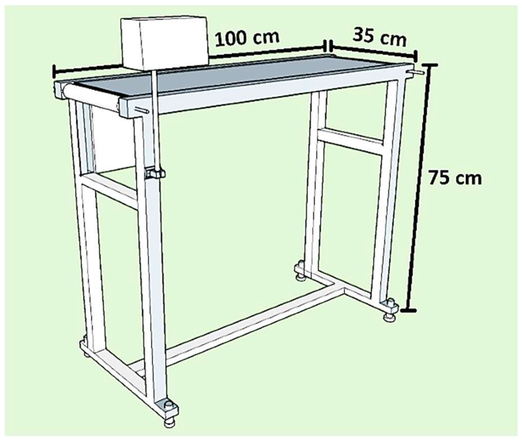
The belt structure was designed using SketchUp 3D model to be implemented with 4x2 cm rectangular iron tubes of 0.8 mm gauge. One of the upper horizontal profiles, which serves to support the rollers, was designed to be fastened with bolts. This allows the profile to be disassembled if the conveyor belt or any other component requires replacement.
Figure 5 illustrates the designed structure of the conveyor belt.
2.2.3. Roller Design
The rollers are indispensable for ensuring the correct rotation of the conveyor belt and were designed using SketchUp 3D software to facilitate subsequent belt calibration and alignment. For this purpose, an 8 mm shaft bearing system was employed at one end of the belt to align the roller, which is driven by the motor through pulleys. This roller is a fixed drum roller and rotates in conjunction with the smooth shaft, allowing movement through the bearings.
Figure 6 shows a representation of the fixed drum roller.
The opposite end of the belt incorporates a freely rotating drum roller, which is supported by bearings that facilitate its axial movement. The shaft in question is 8 mm threaded to facilitate clamping at both ends following the calibration and alignment of the conveyor belt. The alignment of the belt is achieved via a pair of grooves in each profile into which the roller fits, clamping nuts which enable the necessary adjustments to be made, and tensioners which pull the shaft outward. A representation of the idler pulley is shown in
Figure 7.
2.2.4. Cutting System
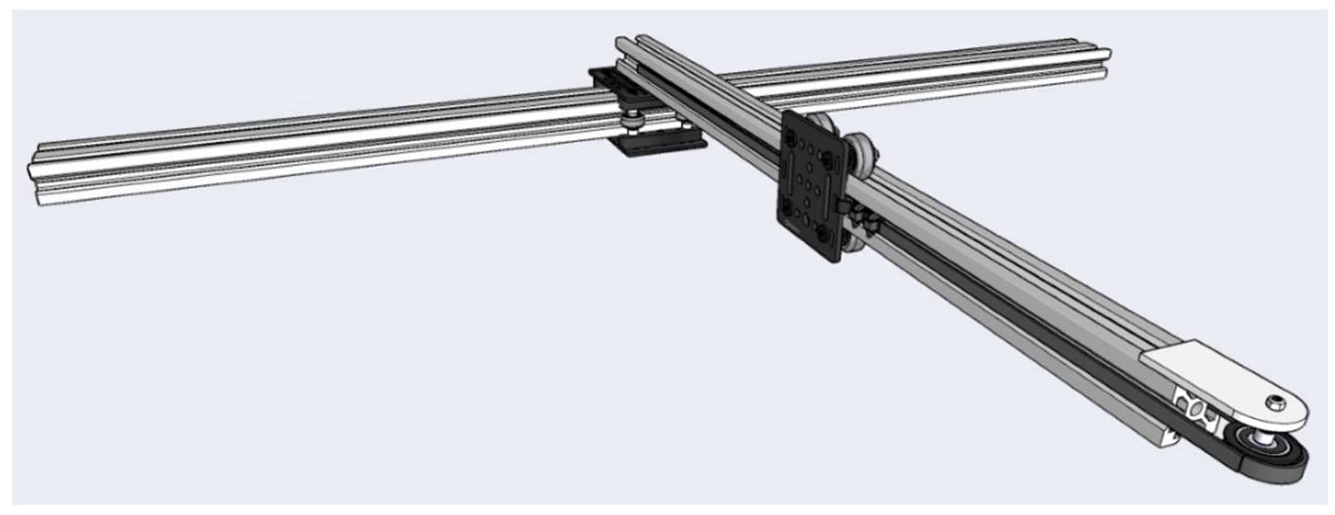
Validation of the design and operation of the flying cutting plant is carried out by evaluating its ability to execute a precise cutting path, characterized by uniformity and the absence of zigzagging patterns. To achieve this, it is essential that parts are arranged in the correct configuration and that the motors or actuators move with precision. Consequently, a cutting system was designed comprising a three-dimensional plane defined by X, Y, and Z coordinates. The X and Y axes are driven by two motors, while an actuator or servo generates the movement along the Z axis, performing the cutting path.
Figure 8 illustrates an example of the cutting system.
To develop the system depicted in
Figure 8, it is essential to consider kinematic aspects within both the system and the designated conveyor belt area, as increasing the total area requires a proportional increase in the length of the X and Y axes. This resulted in the designation of an area of 80\% as the upper limit for the conveyor belt, thus ensuring scalability for the cutting system and its potential deployment in other applications that require Cartesian movement, such as CNC machines or a modular laser cutting system. In contrast, the linear motion of the cutting system is achieved through the use of V-SLOT extruded aluminum profiles and high-precision bearings, which are frequently implemented in the manufacture of 3D printers, CNC machines, Cartesian robots, and other similar devices. In conclusion, the Z-axis is actuated by a servomechanism derived from that used in drawing machines, which incorporates linear bearings and a base for fixing the cutting point. The design of the cutting system, developed in SketchUp 3D model design is illustrated in
Figure 9.
2.2.5. Electronic Circuits
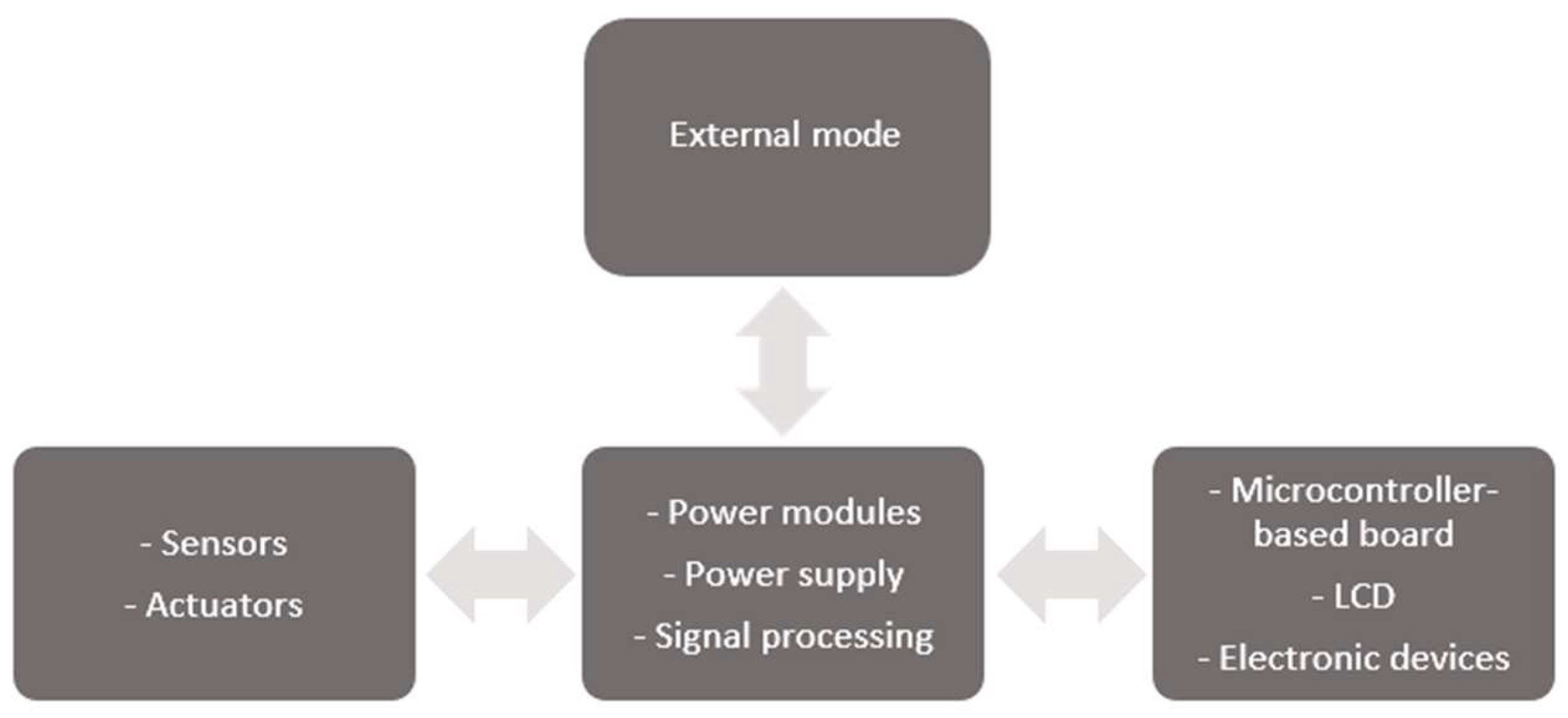
The electronic circuits were designed with scalability in mind. The objective was to facilitate rapid and intuitive connections between the devices necessary for integration at the time of implementation.
Figure 10 illustrates the block diagram proposed in this research as a potential solution for the real-world implementation of the plant. The design of electronic circuits describes a general connection, highlighting three primary groups: the mechanical system, where sensors, including limit switches, encoders, DC motors, stepper motors, and servos, would reside. The second group consists of the power board, which contains the necessary drivers and signal conditioning for the management of sensors, actuators, and embedded control systems. The last group is the control board, which enables user interaction with the cutting plant during operation.
Figure 11 illustrates the internal connection of electronic circuits.
3. Results
3.1. Mechanical Parameter Validation
The mechanical system of the proposed flying cutting plant is a system with finite movement on the different axes, which are limited to the dimensions of the conveyor belt. Therefore, it is essential to determine the operating limits of each of the elements that comprise the mechanical transmission system, so that they can subsequently be validated through experimental testing.
The belt drive consists of the rollers shown in
Figure 6 and
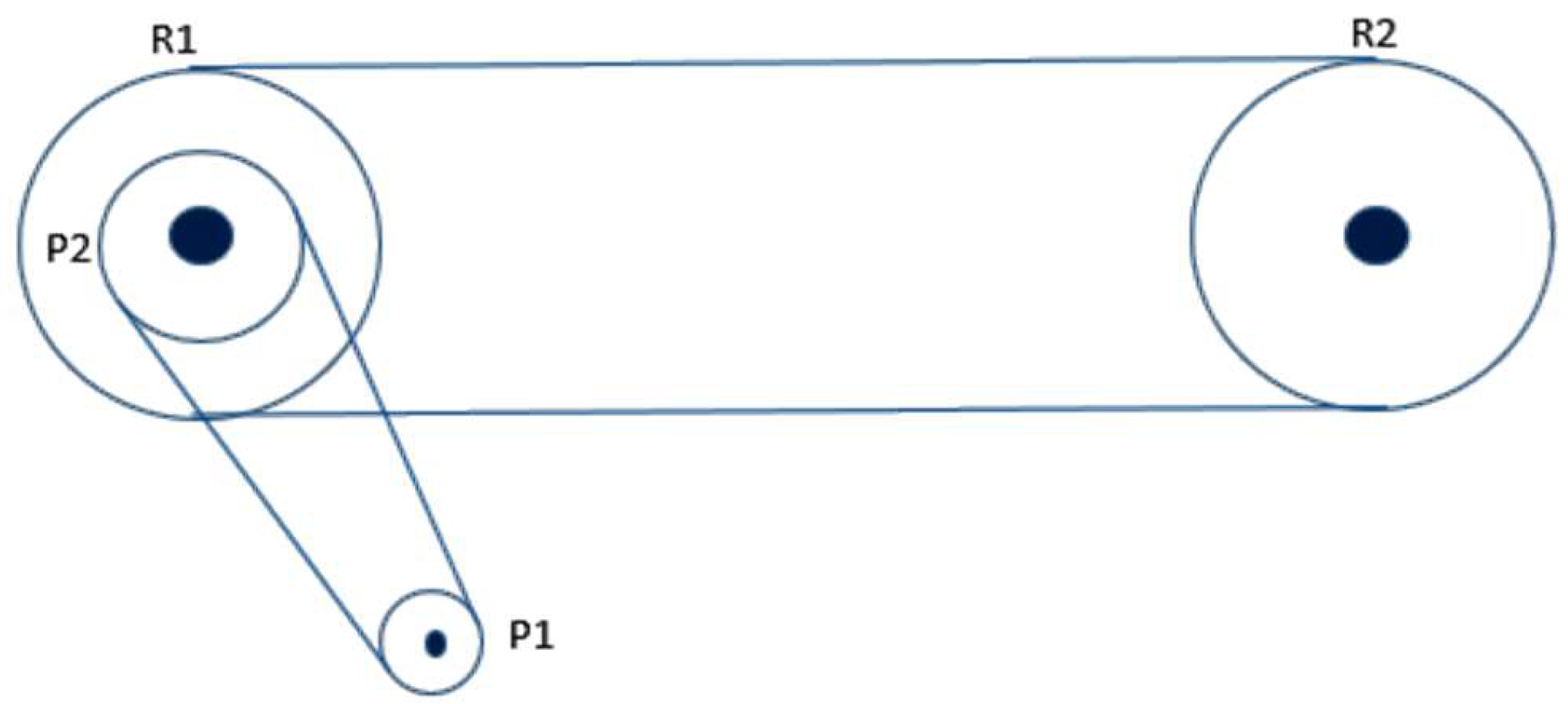
Figure 7 and a system of pulleys that connect one of the rollers to the motor used to move the belt. The mechanical system used to move the conveyor belt is shown in
Figure 12.
In theory, the maximum angular speed that can be reached by the output of the conveyor belt motor gearbox is 100 rpm, the same speed that can be reached by the pulley P1. In this sense, to know the tangential speed at which the rollers move, we use the values of the radius of the pulleys and rollers shown in
Table 1 and must resort to the relations of uniform circular motion. For this, we have the following relations:
Converting to radians per second, the angular speed of the pulley P1 is as follows:
The angular velocity is transmitted to pulley P2 linearly; therefore, the tangential speed v_1 at pulley P1 is equal to the tangential speed v_2 at pulley P2.
Using (6) we can know the angular speed at the pulley P2:
As the pulley P2 is attached to the roller axis R1, both rotate at the same angular speed.
Due to the fact that the two rollers have the same radius, the speed of both rollers is the same. From the angular speed of roller R1, the tangential speed of rollers R1 and R2 can be known, which corresponds to the speed of the conveyor belt.
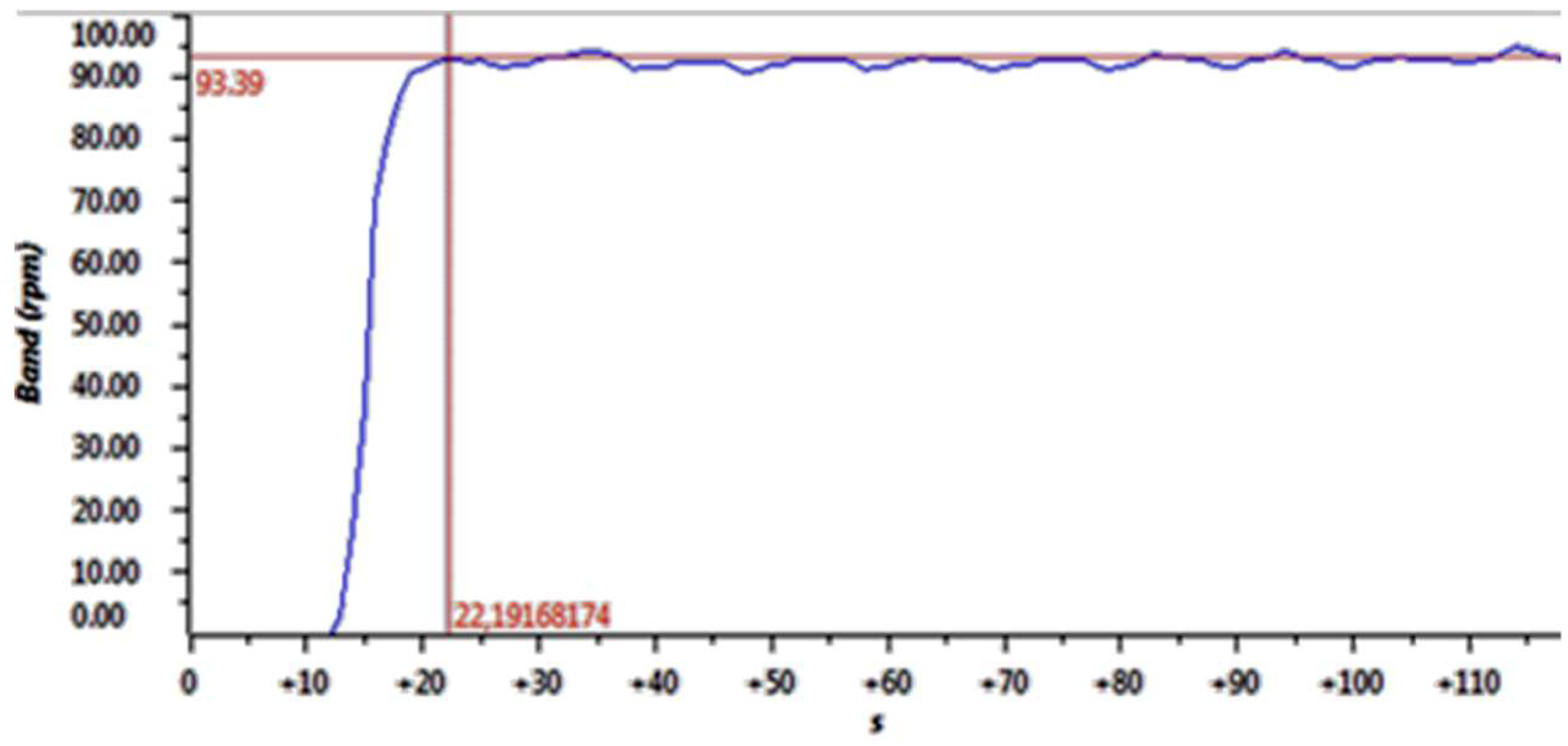
After carrying out a theoretical analysis to determine the relationship between speeds in the mechanical system of the conveyor belt, experimental tests were carried out to validate the results obtained. As shown in
Figure 13, when the maximum tension is applied to the motor, it reaches a speed of 93.39 rpm, which corresponds to a real linear speed of 11.40 cm/s on the conveyor belt.
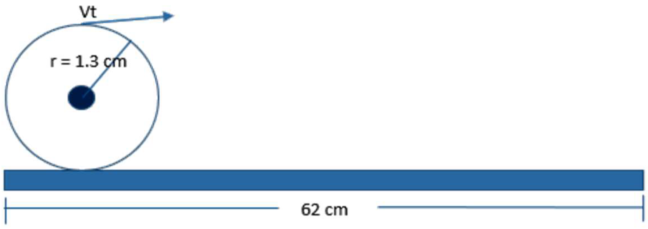
Similarly to the conveyor belt motor, a theoretical analysis was performed for the X-axis motion of the cutting system. In this case, in order to avoid damage or movement along the X axis exceeding the length of the conveyor belt, it was necessary to set limits at each end of the cutting system shown in
Figure 9. After these adjustments, it was determined that the movement of the cutting system along the X-axis was 62 cm. A representation of this is shown in
Figure 14.
The analysis of the movement of the cutting system in the X-axis must be able to match the speed of the conveyor belt. To achieve this, the pulley that holds the motor must possess the same characteristics as the fixed pulley of the drive roller (
Figure 6). Another significant aspect of the movement of the X-axis is the presence of a gearbox analogous to that of the conveyor belt motor. This configuration allows for a theoretical maximum speed of 100 rpm. Consequently, the tangential speed of the X-axis for the cutting system can be expressed as follows:
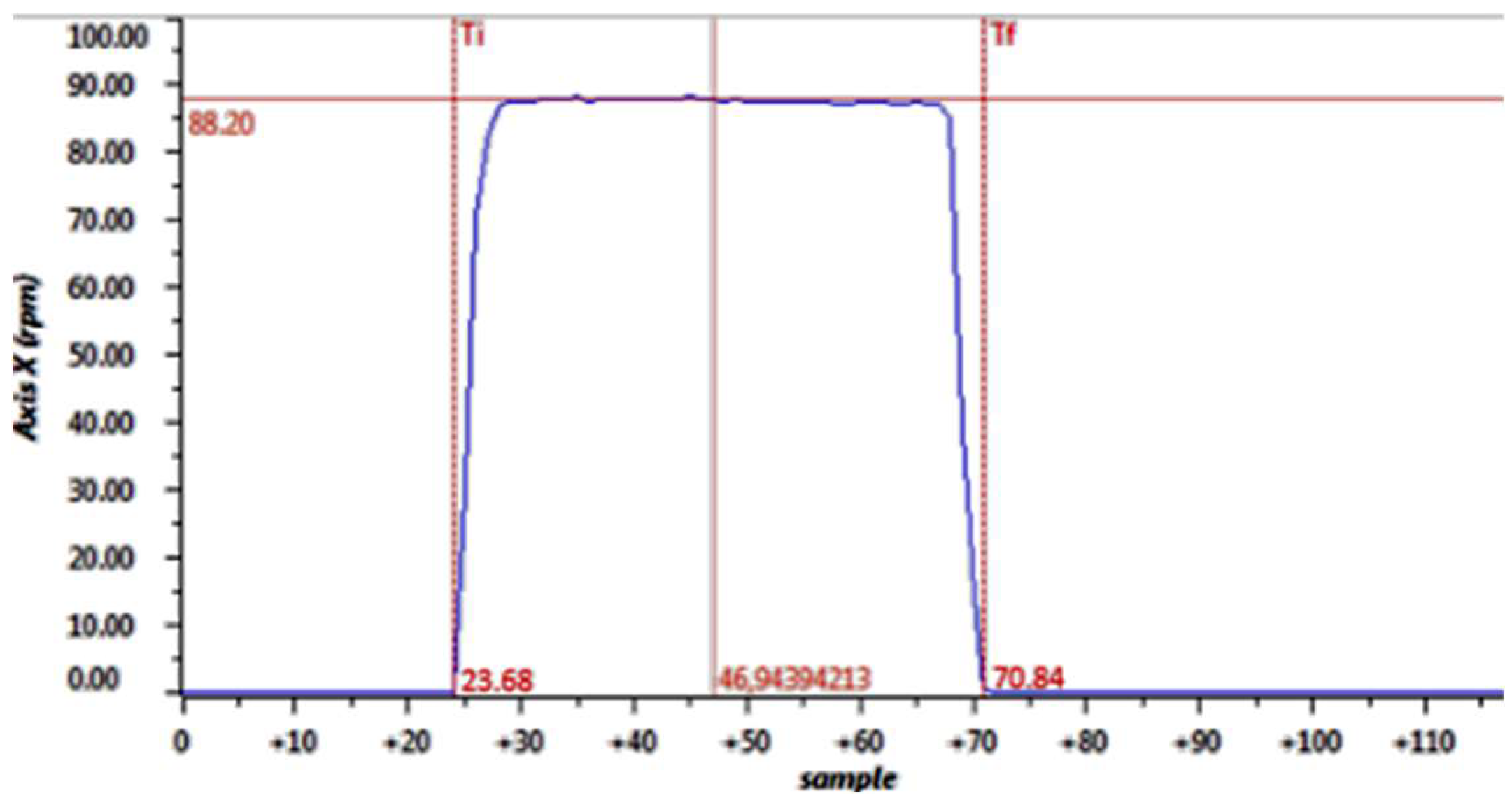
From the tangential speed of the X-axis motor, which has been established previously in (11), the X-axis cutting system can traverse the entire workpiece length in approximately 4.55 seconds, which represents the maximum allowable time for the system to complete a single cutting operation.
Figure 15 illustrates the operational characteristics of the motor used in the X-axis cutting system. It can be seen that the maximum speed attained was 88.20 rpm, which is equivalent to a tangential speed of 12.0 cm/sec. In contrast, the time required to traverse the distance between the two endpoints was determined to be 4.71 seconds. This value was calculated by subtracting the number of start and end samples from the predefined sample time of 0.1 seconds, which was used for simulation purposes.
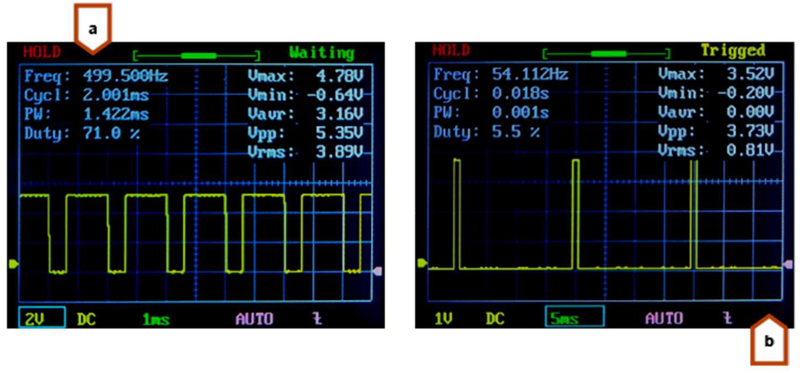
With regard to the angular velocity of the Y-axis cutting system, the maximum angular speed of 214 rpm was reached from a square wave of 714 Hz. This process was established through experimentation with varying frequencies in the signal that controls the Y-axis motor driver. The displacement along the Y-axis of the cutting system has been defined as 30.5 cm, based on the width of the conveyor belt, and is guaranteed through the use of two sensors that determine the beginning and end of the journey. The maximum frequency that enabled this displacement was 500 Hz, with a useful cycle of 71%, a peak voltage of 4.78 V and a Root Mean Square (RMS) voltage of 3.89 V. In order to facilitate the movement of the cutting system in the Z-axis, a PWM signal was generated with a frequency of 50 Hz. The duration of the signal remaining at a high level was modified in order to achieve a variation in the angle of rotation.
Figure 16 illustrates the configurations that were created for simulations and tests of the motor response to movements on the Y and Z axes of the cutting system.
The data illustrated in
Figure 16.b indicates that an angular displacement of 0° with respect to the Z-axis servo motor causes the cutting blade to be positioned on the workpiece to be cut. Furthermore, it is observed that an angular displacement of 50° is sufficient to return the blade to its initial position.
3.2. Electronic Circuits
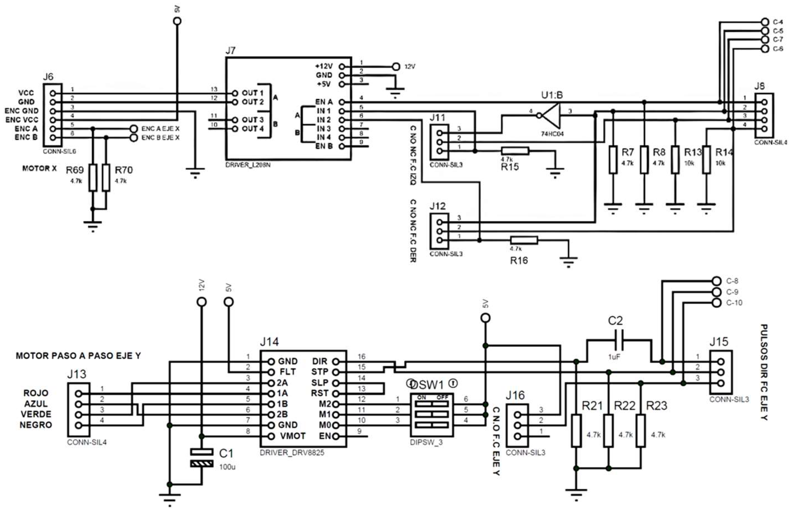
The power circuits illustrated in
Figure 17 was designed with the objective of facilitating an easy connection to the two L298N drivers, which are responsible for propelling the geared motors that control the conveyor belt and the X-axis of the cutting system. In addition, a DRV8825 driver has been incorporated to regulate the Y-axis stepper motor within the cutting system, and a set of connection pins has been incorporated to allow direct linkage with a development PCB. Moreover, the design features specific connection pins for the switching circuit. Furthermore, the power circuit was designed to include terminal blocks, Molex, USB and RJ-45 connectors for interconnection with other components of the cutting plant, such as a power supply, sensors, actuators, control circuits, a programming interface and so forth. This ensures that the system is scalable and modular.
The circuit illustrated in
Figure 17 - down features a dip switch that serves to define the operational steps of the motor. The capacitor C2 and resistor R21 collectively form an RC circuit, also known as a high-pass filter. This configuration allows the passage of frequencies that exceed the cutoff frequency, which in turn serves to mitigate any potential interference generated by lower frequencies.
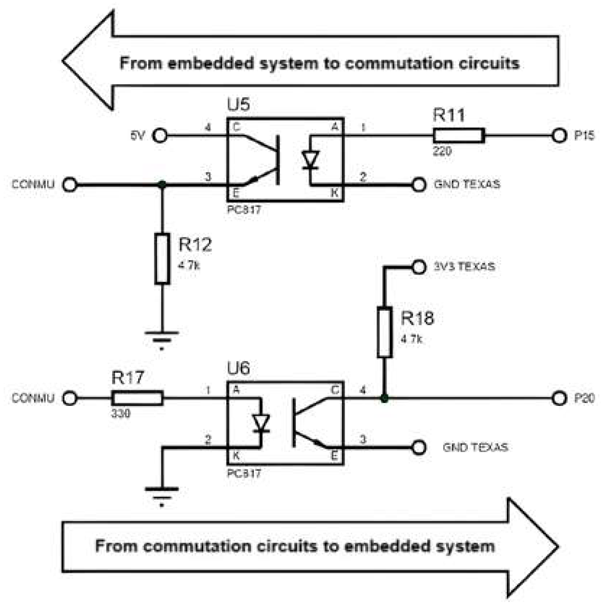
Optocoupler isolation may be employed for the transmission and reception of data between the control and power PCBs. However, due to the switching delays of the PC817 optocouplers, which range between 4 µs and 5 µs, an electronic circuit was designed with high-speed 6N137 optocouplers, which have a propagation delay between 48 ns and 50 ns, suitable for transfer rates up to 115200 Baud. The designed circuit is shown in
Figure 18.
The designed power circuit also incorporates the following features:
The option to utilize either an internal or external power supply.
A latching circuit that enables the start LED to remain illuminated. This is initiated upon pressing the start button and deactivated upon pressing the stop button.
The ability to select either digital pins or the Enhanced Quadrature Encoder (EQEP) module, which is commonly integrated into embedded systems, for the encoder readout pins.
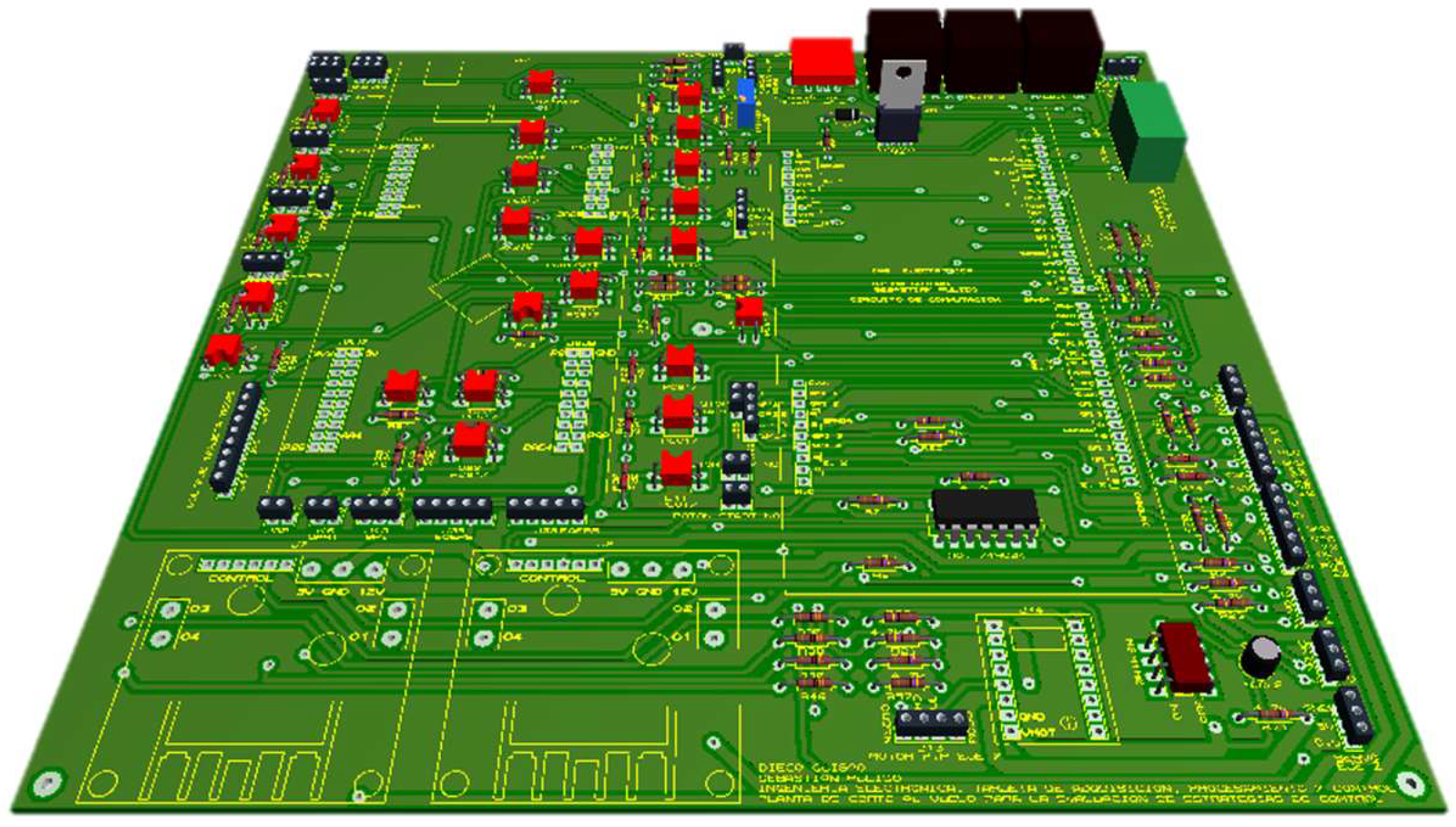
Finally,
Figure 19 shows the 3D design of the power circuit.
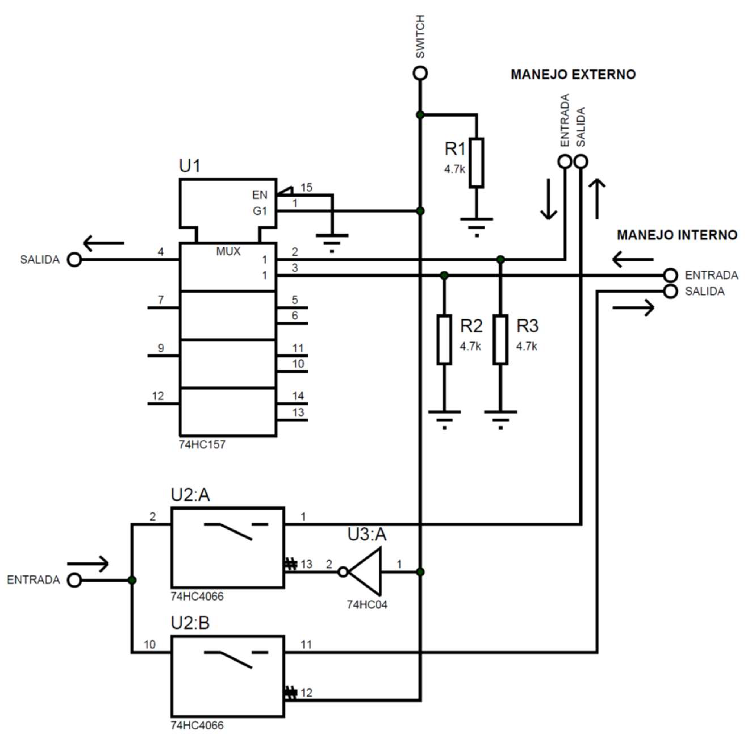
To perform the signal switching and to enable control from the device that performs the processing, it is necessary to take into account whether the signal is read or written, since this determines the use of multiplexers or demultiplexers. The latter are constructed with analogue switches. The reference integrated circuit used for multiplexing signals is the 74HC157, while the 74HC4066 integrated circuit is used for demultiplexing. The electronic configuration for the multiplexing and demultiplexing signals is illustrated in
Figure 20.
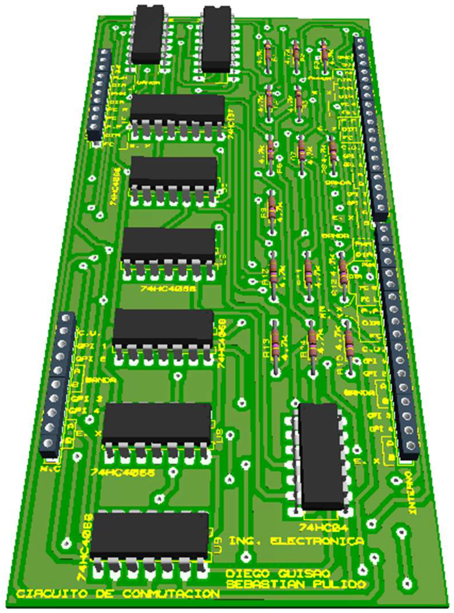
A comparable methodology is employed for all input and output signals intended for commutating, including but not limited to pulse width modulation (PWM), gearmotors, steering, stepper motor control, servo duty cycle, encoder read pulses, general-purpose input and output signals, etc. After the delineation of the input and output signals that can be utilized by the commutation circuit, its three-dimensional model is generated, as illustrated in
Figure 21.
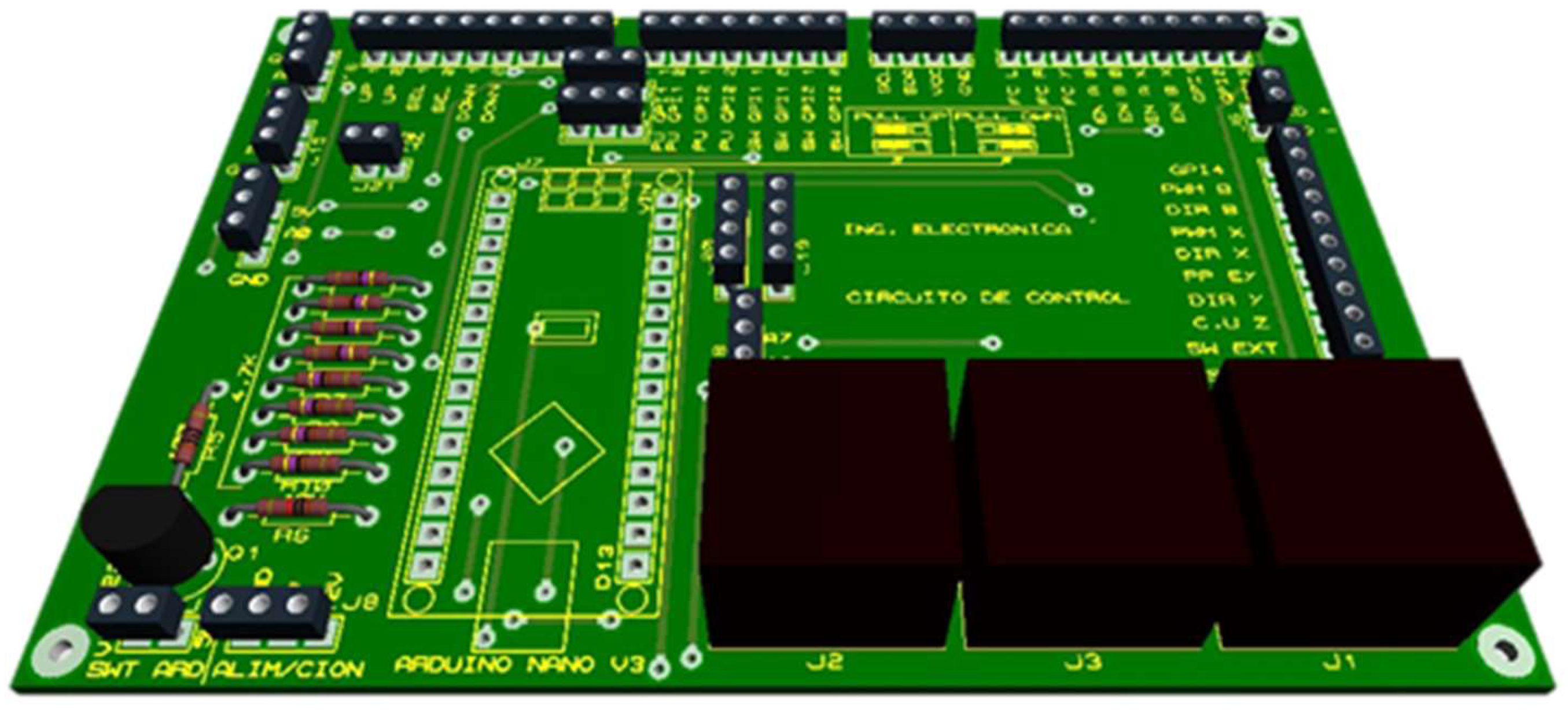
The main function of the control circuit is to act as a conduit between the user interface and the power circuit. Consequently, the circuit was constructed with three RJ-45 connectors to facilitate the transmission of signals for sensor and actuator management, serial communication, general purpose ports, and other applications. An Arduino Nano was incorporated into the design to facilitate the visualization of information and the transmission of corresponding values to the power circuits. The control circuit was configured to accommodate a buzzer, jumpers for the configuration of pull-up or pull-down resistors, general-purpose ports, I2C communication pins for the LCD, and a power supply for supplementary connections. The control circuit design is illustrated in
Figure 22.
3.3. System Programming
The integration of the designed plant's functionalities (comprising mechanical elements and electrical circuits) necessitates the implementation of a programming strategy for each individual module and card. Furthermore, it is essential for all these elements, collectively, to establish communication with the plant. A variety of software tools are available to program this type of system, and the programmer may select any of them according to their preferences and experience. In this particular case, several alternatives were considered, including the software programs Energia, Arduino, and Code Composer Studio (CCS). Energia is an open-source integrated development environment (IDE) based on Wiring and Arduino framework. It allows the development of applications in high-level programming, as presented in [
22].
Another application that was explored was CCS, an integrated development environment (IDE) that has a C/C++ compiler, a source code editor, a debugger, and other features that allow the user to manage their workspace in a straightforward manner, thereby making it a viable alternative for the development of a variety of applications. For this research, we selected CCS as the most suitable tool. If the designed plant is implemented in the future, the tool will enable the programmer to create microcontroller-based embedded systems for real-time applications such as those used in Texas Instruments systems based on C2000 microcontrollers [
23,
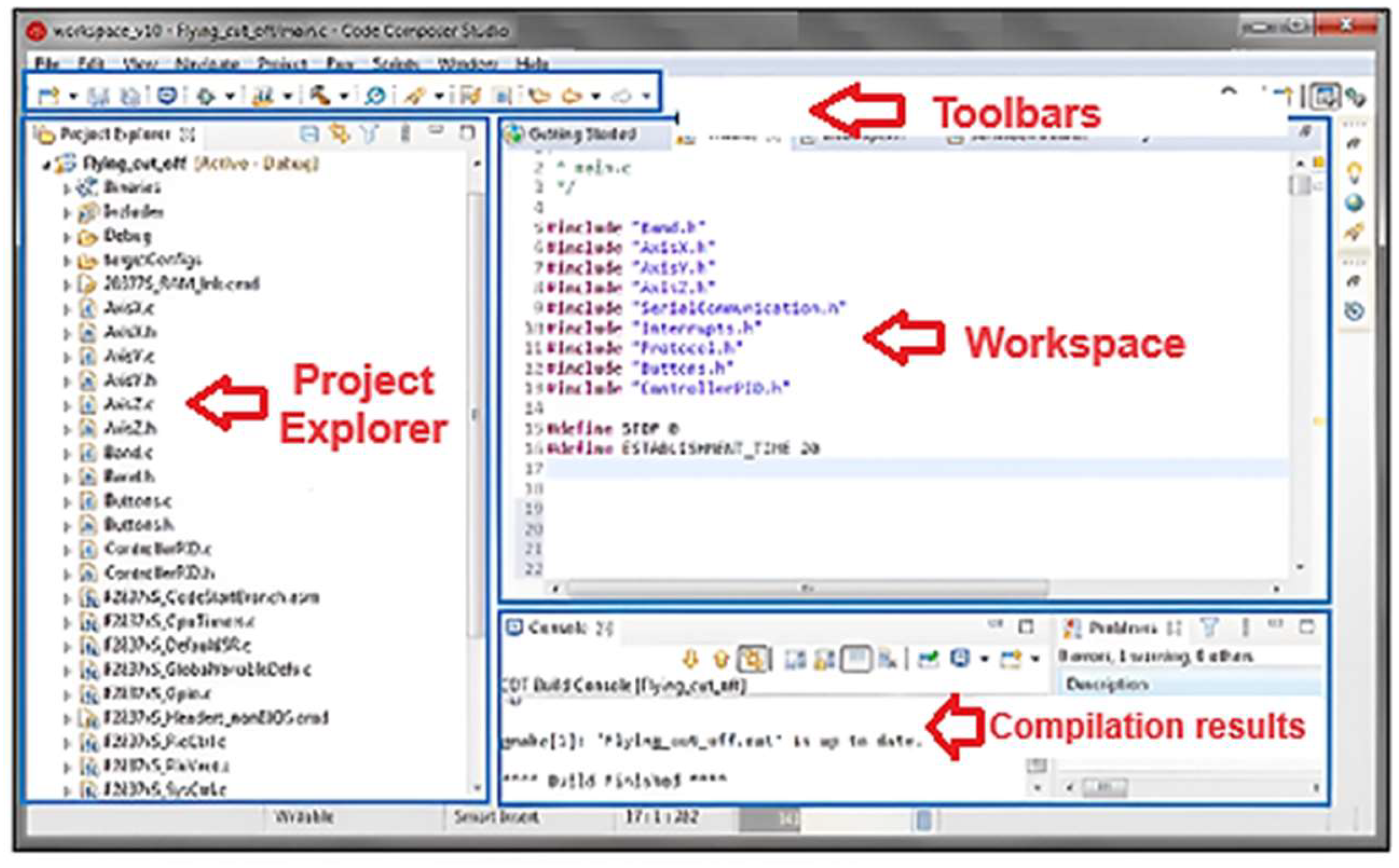
24]. The CSS workspace in its desktop version is shown in
Figure 23.
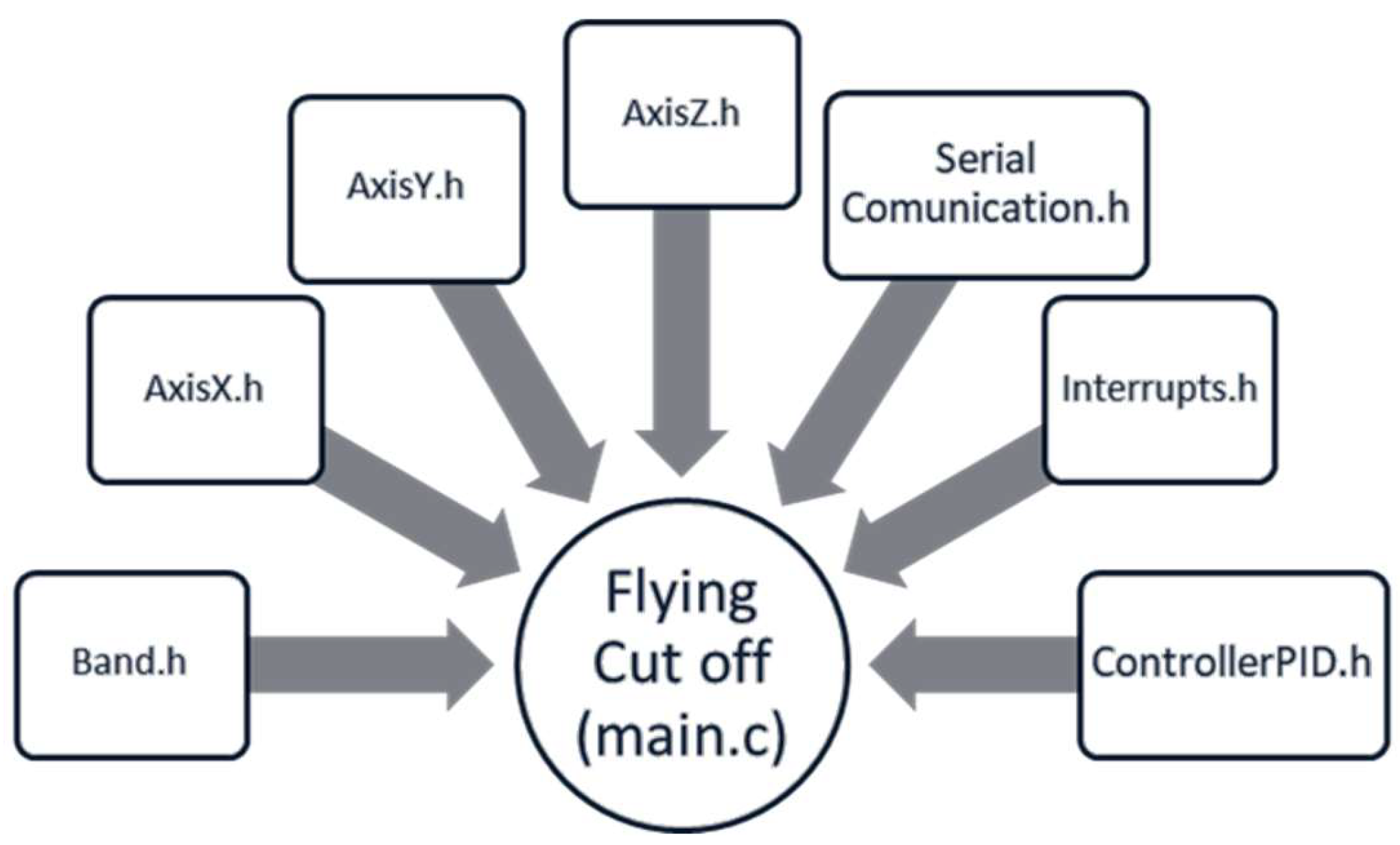
A review of the CCS editor's work environment indicates that its programming structure is comparable to that of other development environments. The programming may be developed in the C language, as the default compiler used in CCS is ANSI C89. As the objective of the designed plant was to integrate all the modules and devices constructed, programming was conducted in a global project, resulting in the generation of numerous native files. These files contain the essential functions required for the management of sensors and actuators of the cutting plant and are particularly pertinent for the real-time control of the components. The files used for the development of the simulation are presented in A1.
Figure 24 illustrates the defined programming structure for the proposed flying cutting plant.
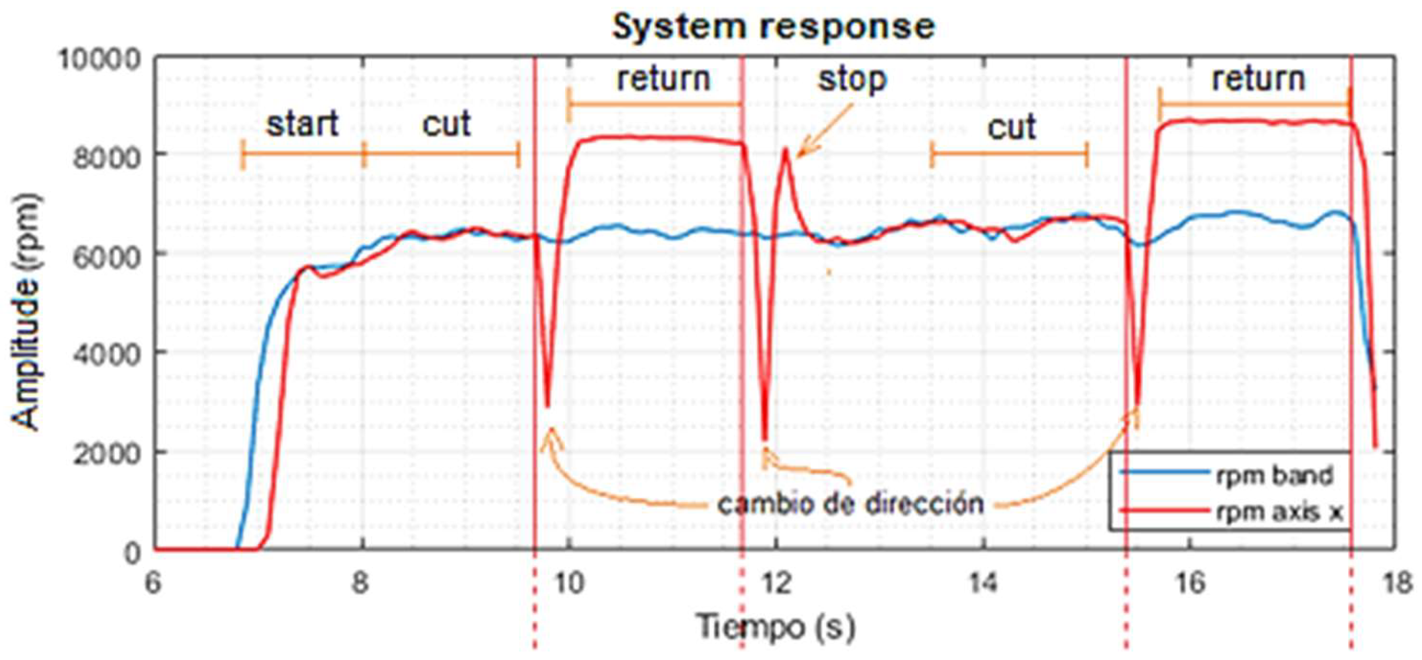
Subsequently, the on-the-fly cutting plant was subjected to simulation and operational tests following the modeling and simulation of all circuits. The system responses are presented after a period of six seconds, during which the conveyor belt is in an inactivity state, representing a useful cycle 0%, and the cutting system is in its initial position. At 6.8 seconds, a duty cycle 50% is established on the conveyor belt, and 1.8 seconds elapse for the belt speed to stabilize at approximately 6330 rpm. From this point on, a set point for the conveyor belt movement was established, resulting in the geared motor coming out of rest (red signal).
In contrast, between 8 and 9.7 seconds, the cutting trace is generated following the equalization of both speeds. Subsequently, a downward peak is observed at 9.8 seconds (red signal), accompanied by an increase in revolutions to approximately 8344. This is attributed to a change of direction in which the X-axis geared motor pauses for an instant before returning to its initial position with maximum speed. The X-axis geared motor, situated in the initial position, ceases movement after 11.9 seconds, reverses direction, and generates a further peak in revolutions. This prevents the motor's inertia from causing additional movement and contact with the left stop. Following the application of the brake to the X-axis motor, it was observed that after 12.1 seconds, the system responded and acted in such a way that the speed of the X-axis was synchronized with the belt, resulting in a second stroke. The summary of the operation is presented in
Figure 25.
4. Conclusions
This research presents a significant advancement in the creation of industrial plant prototypes within an academic framework, serving as an invaluable resource for engineers seeking training in control and automation. The core methodological innovation lies in the design and simulation of a cost-effective, small-scale cutting plant that replicates continuous cutting processes found in industry. This method allows students to understand and manage extensive processes within a lab environment, offering a practical experience comparable to industrial settings without the high expenses associated with commercial apparatuses.
From an engineering standpoint, the study synthesizes key concepts from control theory, mechanical engineering, and physical principles to construct a prototype that facilitates education and hands-on experimentation with real-time control systems. The design's validation via MATLAB simulations, along with the usage of tools like Code Composer Studio for developing real-time controllers, underscores the plant's efficacy as both an educational and research model, adaptable to various contexts.
Moreover, such research is pivotal in closing the gap between theoretical knowledge and practical application in engineering education. The developed prototype provides students with the opportunity to engage with authentic industrial processes, thereby enriching their understanding of complex system dynamics and promoting the development of innovative and efficient industrial solutions using emerging technologies like 3D printing and augmented reality. These factors make the prototype a crucial asset in training future engineers, equipping them to tackle the demands of industrial automation and control.
Author Contributions
Conceptualization, DF.R-J. and CA.TV.; methodology, DF.R-J. and CA.TV.; software, DF.R-J. and CA.TV.; validation, DF.R-J. and CA.TV.; formal analysis, DF.R-J. and CA.TV; investigation, DF.R-J. and CA.TV.; resources, DF.R-J. and CA.TV.; data curation, DF.R-J. and CA.TV.; writing—original draft preparation, DF.R-J. and CA.TV.; writing—review and editing, DF.R-J. and CA.TV.; visualization, DF.R-J. and CA.TV.; supervision DF.R-J. and CA.TV.; project administration, DF.R-J. and CA.TV.; funding acquisition, DF.R-J. and CA.TV. All authors have read and agreed to the published version of the manuscript.
Funding
This research received no external funding.
Data Availability Statement
Data are contained within the article.
Conflicts of Interest
The authors declare no conflicts of interest.
References
- F. Humanidades y Ciencias Sociales, “Evolución de las tecnologías educativas desde su origen.” Accessed: Jul. 09, 2024. [Online]. Available: https://www.ui1.es/blog-ui1/evolucion-tecnologias-educativas.
- “El impacto de las TIC en la Educación Universitaria.” Accessed: Jul. 09, 2024. [Online]. Available: https://www.ui1.es/blog-ui1/el-impacto-de-las-tic-en-la-educacion-universitaria.
- L. M. Nkomo, B. K. Daniel, and R. J. Butson, “Synthesis of student engagement with digital technologies: a systematic review of the literature,” International Journal of Educational Technology in Higher Education, vol. 18, no. 1, p. 34, Jun. 2021. [CrossRef]
- N. Kerimbayev, Z. Umirzakova, R. Shadiev, and V. Jotsov, “A student-centered approach using modern technologies in distance learning: a systematic review of the literature,” Smart Learning Environments, vol. 10, no. 1, p. 61, Nov. 2023. [CrossRef]
- H. Crompton and D. Burke, “Artificial intelligence in higher education: the state of the field,” International Journal of Educational Technology in Higher Education, vol. 20, no. 1, p. 22, Apr. 2023. [CrossRef]
- J. G. Castro Lugo, J. J. Padilla Ybarra, and E. Romero A., “Metodología para realizar una automatización utilizando PLC,” Revista de Ingeniería Eléctrica, Electrónica y Computación, vol. 1, pp. 18–21, Dec. 2005.
- A. P. Lorandi Medina, G. Hermida Saba, J. Hernandez Silva, and E. L. De Guevara Durán, “Los Laboratorios Virtuales y Laboratorios Remotos en la Enseñanza de la Ingeniería,” Revista Internacional de Educación en Ingeniería, vol. 4, pp. 24–30, 2011.
- C. Losada-Gutierrez, F. Espinosa, C. Santos-Perez, M. Marron-Romera, and J. M. Rodriguez-Ascariz, “Remote Control of a Robotic Unit: A Case Study for Control Engineering Formation,” IEEE Trans. Educ., vol. 63, no. 4, pp. 246–254, Nov. 2020. [CrossRef]
- N. Peric and I. Petrovic, “Flying shear control system,” IEEE Trans. on Ind. Applicat., vol. 26, no. 6, pp. 1049–1056, Dec. 1990. [CrossRef]
- J. C. Song, C. Z. Wang, and D. Xu, “Dynamic Simulation and Control Strategy of Centrifugal Flying Shear,” AMM, vol. 16–19, pp. 278–282, Oct. 2009. [CrossRef]
- A. Serrano Huertas and O. A. López Madrid, “Diseño de una cizalla industrial para el corte de láminas de acero al silicio utilizadas en transformadores secos de energía eléctrica.,” Universidad Tecnológica de Pereira, Facultad de Tecnologías, 2015.
- E. Caicedo Bravo, E. B. Bacca, B. A. Calvache, J. E. Cardona Aristizabal, and J. A. Buitrago, “Laboratorio distribuido con acceso remoto para la enseñanza de la robótica,” Revista Educación en Ingeniería, vol. 7, pp. 51–61, Jun. 2009.
- J. Aravena, D. Carrasco, M. Uriarte, E. Contreras, M. Díaz, and F. Donoso, “Design and Implementation of an Interface Board for a Real-Time Control System based on the LAUNCH-XL F28379D board,” in 2021 IEEE CHILEAN Conference on Electrical, Electronics Engineering, Information and Communication Technologies (CHILECON), Valparaíso, Chile: IEEE, Dec. 2021, pp. 1–5. [CrossRef]
- D. Rosinová and R. Schwarz, “Teaching State-Space Control Methods Using a Floatshield Laboratory Plant,” in 2023 24th International Conference on Process Control (PC), Strbske Pleso, Slovakia: IEEE, Jun. 2023, pp. 261–266. [CrossRef]
- J. G. H. Gutiérrez, J. E. Cardona, P. Muñoz-Gutiérrez, and D. F. Ramírez-Jiménez, “Rapid control prototyping using free software of the position control of a two degree of freedom robot,” presented at the XIV Congreso Internacional de Electrónica y Tecnologìas de Avanzada, Universidad de Pamplona: Universidad de Pamplona, Oct. 2020, pp. 1–6.
- “Productos,” RISHBIN WUXI CO., LTD. Accessed: Jul. 05, 2024. [Online]. Available: http://es.rishbin.com.
- K. Ghosh, “A Study on Kinematic Analysis of Crank-Type Flying Shear Mechanism for Production-Oriented Design and Motion Control,” J. Inst. Eng. India Ser. C, vol. 100, no. 6, pp. 851–858, Dec. 2019. [CrossRef]
- Schneider Electric España, Schneider Electric: Motion control. Corte al vuelo T2-T3, Application Know-How, (Apr. 08, 2019). Accessed: Jul. 05, 2024. [Online Video]. Available: https://www.youtube.com/watch?v=NKDQ9n3aAbw.
- “MATLAB Documentation.” Accessed: Jul. 15, 2024. [Online]. Available: https://www.mathworks.com/help/matlab/index.html?s_tid=CRUX_lftnav.
- “Tune PID controllers - MATLAB.” Accessed: Jul. 15, 2024. [Online]. Available: https://www.mathworks.com/help/control/ref/pidtuner-app.html?s_tid=srchtitle_site_search_1_pid%20tuner.
- “Navigating the SketchUp Interface | SketchUp Help.” Accessed: Jul. 15, 2024. [Online]. Available: https://help.sketchup.com/en/sketchup/user-interface.
- D. F. Ramirez-Jimenez, A. L. Parrado, and J. V. Medina, “Overview of a framework for Implementation of digital controllers in Energia IDE using Texas Instruments microcontrollers,” in 2021 IEEE 5th Colombian Conference on Automatic Control (CCAC), Ibague, Colombia: IEEE, Oct. 2021, pp. 13–18. [CrossRef]
- D. F. Ramírez-Jiménez, P. A. Bedoya-Benítez, and P. A. Munoz-Gutierrez, “Visualization and Control System for a Wastewater Laboratory Plant with Biological Treatment,” Ciencia e Ingeniería Neogranadina, vol. 34, no. 1, Art. no. 1, Jun. 2024. [CrossRef]
- D. F. Ramírez Jiménez, “Sistema de medición y control de temperatura para un prototipo de planta de tratamiento de aguas residuales,” Investigación e Innovación en Ingenierías, vol. 9, no. 1, pp. 100–113, Apr. 2021. [CrossRef]
Figure 1.
Industrial flying cutting plants: (a) T1 tyipe, and (b) T3 type. Source: The authors.
Figure 1.
Industrial flying cutting plants: (a) T1 tyipe, and (b) T3 type. Source: The authors.
Figure 2.
Graphic user interface for MATLAB PID Tuner.
Source: [
20].
Figure 2.
Graphic user interface for MATLAB PID Tuner.
Source: [
20].
Figure 3.
Graphic user interface for SketchUp desktop version.
Source: [
21]
Figure 3.
Graphic user interface for SketchUp desktop version.
Source: [
21]
Figure 4.
Block diagram of the structure of the flying cutting plant. Source: The authors.
Figure 4.
Block diagram of the structure of the flying cutting plant. Source: The authors.
Figure 5.
Structure designed for the conveyor belt. Source: The authors.
Figure 5.
Structure designed for the conveyor belt. Source: The authors.
Figure 6.
Fixed drum roller with bearings and pulley. Source: The authors.
Figure 6.
Fixed drum roller with bearings and pulley. Source: The authors.
Figure 7.
Free drum roller. Source: The authors.
Figure 7.
Free drum roller. Source: The authors.
Figure 8.
Motion coordinates for the cutting system. Source: The authors.
Figure 8.
Motion coordinates for the cutting system. Source: The authors.
Figure 9.
Design and 3D modeling of the cutting system using SketchUp software. Source: The authors.
Figure 9.
Design and 3D modeling of the cutting system using SketchUp software. Source: The authors.
Figure 10.
Block diagram of the electronic circuits of the plant. Source: The authors.
Figure 10.
Block diagram of the electronic circuits of the plant. Source: The authors.
Figure 11.
Block diagram for internal connection of electronic circuits. Source: The authors.
Figure 11.
Block diagram for internal connection of electronic circuits. Source: The authors.
Figure 12.
Pulleys and rollers relationship for the movement of the conveyor belt. Source: The authors.
Figure 12.
Pulleys and rollers relationship for the movement of the conveyor belt. Source: The authors.
Figure 13.
Maximum angular speed achieved by the conveyor belt motor. Source: The authors.
Figure 13.
Maximum angular speed achieved by the conveyor belt motor. Source: The authors.
Figure 14.
Movement of the pulley P2 on the X-axis. Source: The authors.
Figure 14.
Movement of the pulley P2 on the X-axis. Source: The authors.
Figure 15.
Maximum speed reached by the X-axis motor in the cutting system. Source: The authors.
Figure 15.
Maximum speed reached by the X-axis motor in the cutting system. Source: The authors.
Figure 16.
PWM signals for motor operation in the cutting system. a. Motor for motion in the y-axis. b. Motor for motion in the z-axis. Source: The authors.
Figure 16.
PWM signals for motor operation in the cutting system. a. Motor for motion in the y-axis. b. Motor for motion in the z-axis. Source: The authors.
Figure 17.
Power circuit for DRV8825 drivers - down and L298N - top. Source: The authors.
Figure 17.
Power circuit for DRV8825 drivers - down and L298N - top. Source: The authors.
Figure 18.
Tx and Rx circuit for high speed optocouplers. Source: The authors.
Figure 18.
Tx and Rx circuit for high speed optocouplers. Source: The authors.
Figure 19.
3D design made in ARES for the power circuit. Source: The authors.
Figure 19.
3D design made in ARES for the power circuit. Source: The authors.
Figure 20.
Proposed signal switching circuit. Source: The authors.
Figure 20.
Proposed signal switching circuit. Source: The authors.
Figure 21.
3D model for the commutation circuit in
Figure 20.
Source: The authors.
Figure 21.
3D model for the commutation circuit in
Figure 20.
Source: The authors.
Figure 22.
Proposed 3D model for the control circuit. Source: The authors.
Figure 22.
Proposed 3D model for the control circuit. Source: The authors.
Figure 23.
Workspace for the CCS desktop application. Source: The authors.
Figure 23.
Workspace for the CCS desktop application. Source: The authors.
Figure 24.
The programming structure developed for the simulation of the flying cutting plant. Source: The authors.
Figure 24.
The programming structure developed for the simulation of the flying cutting plant. Source: The authors.
Figure 25.
The programming structure developed for the simulation of the flying cutting plant. Source: The authors.
Figure 25.
The programming structure developed for the simulation of the flying cutting plant. Source: The authors.
Table 1.
Radii of pulleys and rollers on conveyor belts.
Table 1.
Radii of pulleys and rollers on conveyor belts.
| Device |
Radius (cm) |
| Poley (P1) |
0.7 |
| Poley (P2) |
1.3 |
| Roller (R1) |
2.165 |
| Roller (R2) |
2.165 |
|
Disclaimer/Publisher’s Note: The statements, opinions and data contained in all publications are solely those of the individual author(s) and contributor(s) and not of MDPI and/or the editor(s). MDPI and/or the editor(s) disclaim responsibility for any injury to people or property resulting from any ideas, methods, instructions or products referred to in the content. |
© 2024 by the authors. Licensee MDPI, Basel, Switzerland. This article is an open access article distributed under the terms and conditions of the Creative Commons Attribution (CC BY) license (http://creativecommons.org/licenses/by/4.0/).

