Preprint
Article

Complex Photonic Integrated Resonators Modeled Using Scattering Matrix Methods

Altmetrics

Downloads

79

Views

20

Comments

0

This version is not peer-reviewed

Submitted:

05 October 2024

Posted:

08 October 2024

You are already at the latest version

Alerts
Abstract
We propose a universal approach for modeling complex integrated photonic resonators based on the scattering matrix method. By dividing devices into basic elements including directional couplers and connecting waveguides, our approach can be used to model integrated photonic resonators with both unidirectional and bidirectional light propagation, with the simulated spectral response showing good agreement with experimental results. A simplified form of our approach, which divides devices into several independent submodules such as microring resonators and Sagnac interferometers, is also introduced to streamline the calculation of spectral transfer functions. Finally, we discuss the deviations introduced by approximations in our modeling, along with strategies for improving modeling accuracy. Our approach is universal across different integrated platforms, providing a useful tool for designing and optimizing integrated photonic devices with complex configurations.
Keywords: 
Subject: Engineering  -   Electrical and Electronic Engineering

1. Introduction

With compact footprint and versatile configuration, integrated photonic resonators have become critical building blocks for photonic integrated circuits (PICs), with applications in a wide range of fields such as optical communications [1,2,3], photonic computing [4,5,6], nonlinear optics [7,8,9], sensing [10,11,12], and optical neural networks [13,14,15].
Modeling the spectral response of integrated photonic resonators is of fundamental importance for their use in different applications. The scattering matrix method (SMM) (also known as the transfer matrix method) [16,17], which is derived based on the Maxwell’s equations for electromagnetic waves, has been widely employed to model the spectral response of integrated photonic resonators with different device configurations [17,18,19,20,21,22].
Although in principle the SMM can be applied to model integrated photonic devices with arbitrary planar configurations [16,23], previous studies mainly focused on modeling devices with simple configurations. A key limitation comes from the fact that the traditional SMM relies on the manual derivation of scattering matrices,, and the obtained scattering matrices need to be multiplied in a specific sequence [24]. For devices with simple configurations, this allows for relatively straightforward calculation of spectral transfer functions. However, for complex integrated photonic resonators, particularly those with bidirectional light propagation, this process becomes much more complicated, which greatly limits its broader applicability.
In this paper, a universal approach based on the SMM is proposed to model integrated photonic resonators with complex structures. The modeling is achieved by dividing a device configuration into basic elements including directional couplers and connecting waveguides, followed by solving a system of linear scattering matrix equations using computational tools. Our approach can be applied to model devices with both unidirectional and bidirectional light propagation, and the simulated spectral response aligns well with measured results for practical devices. The modeling in our approach can also be simplified by dividing the device configuration into independent submodules such as microring resonators (MRRs) and Sagnac interferometers (SIs). Finally, we discuss the limitations of our approach induced by approximations in the modeling, together with strategies for improving modeling accuracy. Our approach provides an effective way for designing and optimizing complex integrated photonic devices across various integrated platforms.

2. Modeling of Devices with Unidirectional Light Propagation

In this section, we use the device configuration shown in Figure 1(a) as an example to show how to model a complex integrated photonic resonator based on the SMM in four steps. The device consists of a microring resonator (MRR) nested within another, with light propagating in only one direction in each waveguide.
First, we divide the device into several directional couplers and connecting waveguides, which are the basic elements in photonic integrated circuits that form integrated photonic resonators. The optical fields at the dividing points between these elements are denoted as Ei (i = 1–16).
Next, we establish a set of scattering matrix equations for the basic elements obtained in the first step, as shown in Table 1. These scattering matrix equations describe the relation between Ei at the input / output ports of the directional couplers and the connecting waveguides. For the directional coupler in Figure 1(b), the field transfer function can be expressed as [16]
E out - 1 E out - 2 = t j κ j κ t E in - 1 E in - 2 ,
where j = - 1 , t and κ are the self-coupling and cross coupling coefficients, which satisfies the relation t 2 + κ2 = 1 when assuming lossless coupling, Ein-1, Ein-2, Eout-1, and Eout-2 are the input and output optical fields right before and after the coupling region. For the connecting waveguide in Figure 1(c), the field transfer function can be given by [23]
T = a e - j φ ,
where a = eαL/2 is the round-trip transmission factor, with α and L denoting the power propagation loss factor and the waveguide length, respectively. In Equation (2), φ = 2πngL/λ is the round-trip phase shift, with ng and λ denoting the group index and the wavelength, respectively. For each directional coupler, two equations can be derived, and one equation can be obtained for each connecting waveguide. This results in 2 × 4 + 1 × 6 = 14 equations in total for the device shown in Figure 1(a), which includes four directional couplers and six connecting waveguides.
Third, the system input is set. For instance, if we assume that there is only a continuous-wave (CW) input from Port 1, then another two equations can be obtained: E1 = 1 and E10 = 0. Here we set E1 as 1 because the spectral transfer function at the output port, such as Port 2, is given by fPort 2 = E3 / E1. By setting E1 to 1, fPort 2 = E3 / E1 = E3, then the transfer function can be directly determined by calculating E3 in the next step.
Finally, by solving all the linear equations obtained in the second and third steps, one can obtain the spectral transfer functions at the output ports. In Table 1, we summarize all the 16 equations for the device in Figure 1(a). In these equations, there are 16 variables Ei (i = 1–16), with the device’s structural parameters denoted using symbols and treated as constant coefficients. By solving this system of linear equations using computational tools (e.g., symbolic calculation in MATLAB), any of the variables Ei (i = 1–16) can be determined as a function of the device’s structural parameters. For example, the spectral transfer function at Port 2 can be given by fPort 2 = E3 (Ti, ti, κi). Assuming that the power propagation loss factor α and the group index ng are constant for the device, the spectral transfer function at Port 2 can be expressed as a function of Li, ti, and κi, i.e., fPort 2 = E3 (Li, ti, κi).
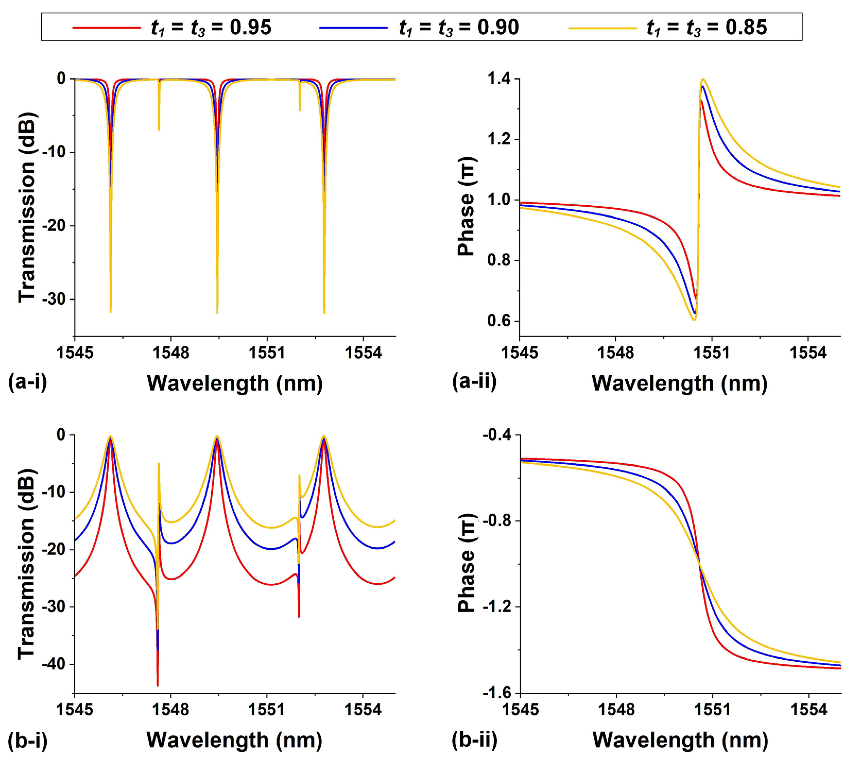
In Figure 2(a), we show the intensity and phase response spectra at Port 2 for different ti based on the obtained spectral transfer function fPort 2 = E2 (Li, ti, κi). Except for the varying parameters, other structural parameters were chosen as follows: L1 = L2 = L3 = L4 = 41.73 µm, L5 = L6 = 62.83 µm, and t2 = t4 = 0.98. By using the same method, we obtain the intensity and phase responses at Port 3 for different ti, as shown in Figure 2(b). In our modeling, we assume that α = 101 m-1 and group index ng = 4.335 based on values obtained from our previously fabricated silicon photonic devices [20,25]. Unless otherwise specified, we use the same values for these two parameters in the modeling for all the devices in the following figures.
Our results in Figure 2 show good agreement with the results in Ref. [26], confirming the effectiveness of our method. Since the obtained spectral transfer functions (e.g., fPort 2 = E2 (Li, ti, κi)) include all the structural parameters, the intensity and phase responses can be easily tailored by adjusting any of these parameters. This provides significant flexibility in designing and optimizing the spectral response of integrated photonic devices with different structural parameters. It should also be noted that our modeling, as mentioned above, is not limited to silicon photonic platforms. By using the corresponding values of α and ng, it is applicable across various integrated platforms such as silicon nitride, doped silica, and lithium niobate [27,28,29,30,31,32,33,34,35,36,37,38,39,40,41,42,43,44,45,46,47,48,49,50,51,52,53,54,55,56,57,58,59,60,61,62,63,64,65,66,67,68,69,70,71,72,73,74,75,76,77,78,79,80,81,82,83,84,85,86,87,88,89,90,91,92,93].

3. Modeling of Devices with Bidirectional Light Propagation

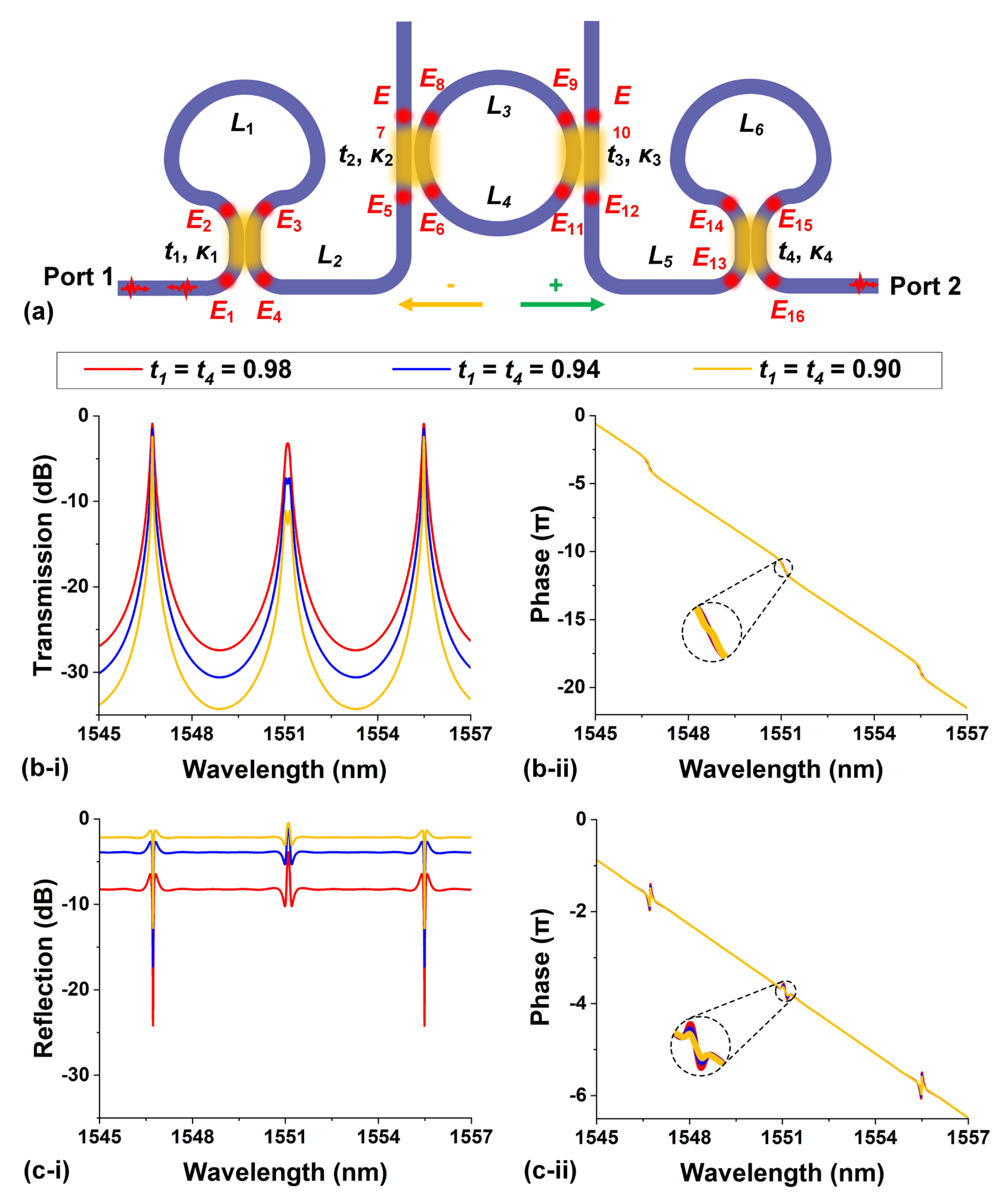
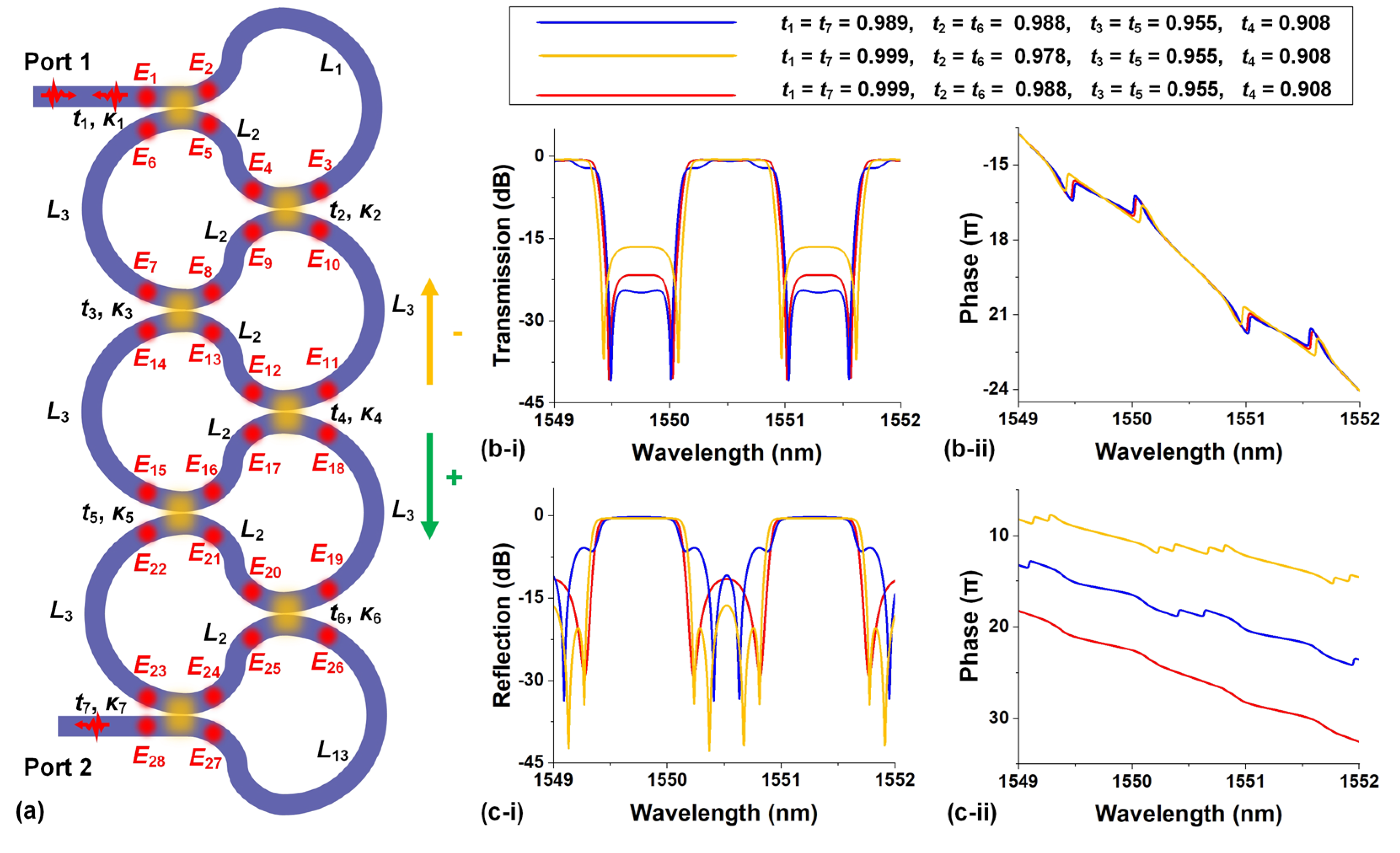
For the device in Figure 1(a), light propagates in only one direction along each waveguide. In more complex integrated photonic resonators with light propagating bidirectionally in the waveguides, the modeling becomes more complicated. In this section, we use the device configuration shown in Figure 3(a) as an example to show how to model a complex integrated photonic resonator with bidirectional light propagation based on the SMM. The device consists of an add-drop (AD) MRR sandwiched between a pair of Sagnac interferometers (SIs), where the SIs introduce back reflection and hence bidirectional light propagation in such device.
To model the device in Figure 3(a), we first divide it into several directional couplers and connecting waveguides ‒ the same as what we did for the device in Figure 1(a). The optical fields at the dividing points between directional couplers and connecting waveguides are denoted as Ei (i = 1–16). Since there are optical fields traveling in two different directions at each dividing point, the optical fields traveling from left to right or in a clockwise direction are defined as “+”, and the opposite direction is defined as “−”.
In the second step, we establish 28 scattering matrix equations describing the relation between Ei+ and Ei- at the input / output ports of the directional couplers and the connecting waveguides, as shown in Table 2. For each directional coupler, four equations can be derived, and two equations can be obtained for each connecting waveguide. Note that the number of equations is doubled due to the bidirectional light propagation in such device.
In the third step, we obtain another four equations by setting the system input. If we assume that there is only a CW input from Port 1, then the four equations are: E1+ = 1, E7 = 0, E10+ = 0, and E16 = 0. Here the number of equations is also doubled due to the bidirectional light propagation.
Finally, by solving all the 32 linear equations obtained previously (which include 32 variables, i.e., Ei+ and Ei-, i = 1–16), we can obtain the spectral transfer functions at all the output ports. For example, the transfer function for forward transmission, with output at Port 2, is fPort 2 = E16+ (Li, ti, κi), whereas the transfer function for backward reflection is fPort 1 = E1- (Li, ti, κi), with output at Port 1. It should be noted that as the number of equations increases or the device configuration becomes more complex, the use of computational software to solve the system of linear equations offers significant advantages as compared to manual derivation of the spectral transfer functions as those in Refs. [25,26].
Based on the obtained spectral transfer functions at Port 2 and Port 1, we plot the corresponding response spectra for different ti, as shown in Figure 3(b) and Figure 3(c), respectively. Except for ti, the other structural parameters are kept as constant as: L1 = L6 = 129.66 µm, L2 = L5 = 77.67 µm, L3 = L4 = 63.33 µm, and t2 = t3 = 0.95. Our results in Figure 3 also show good agreement with the results in Ref. [25], confirming the effectiveness of our method in modeling complex integrated photonic resonator with bidirectional light propagation.

4. Simplification by Dividing Device into Submodules

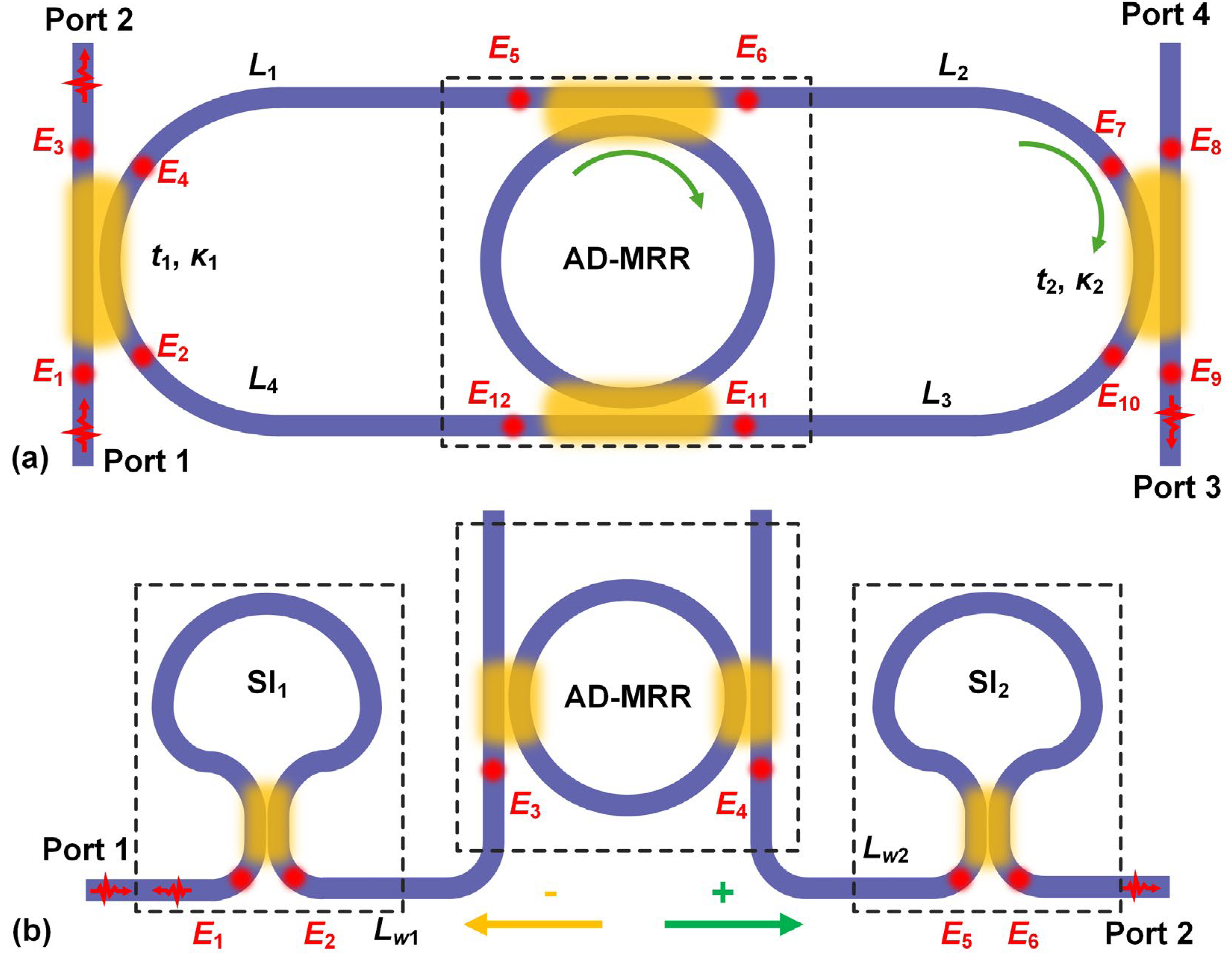
In modeling of the device configurations inFigure 1(a) and Figure 3(a), the devices were divided into several basic elements including directional couplers and connecting waveguides. To reduce the number of equations and simplify the calculation of the spectral transfer function, the device configuration can also be divided into several independent submodules such as MRRs and SIs, which are formed by the basic elements.
As illustrated in Figure 4(a), the AD-MRR at the center of the device in Figure 1(a) is treated as an independent module, with the field transfer functions at the through and drop ports denoted as TRR and DRR, respectively. This results in 12 equations in total obtained by using our method mentioned previously, as summarized in Table 3. In comparison to the 16 equations obtained for the same device configuration in Table 1, the number of equations is reduced, which helps to simplify the solving of the system of equations. By solving the 12 equations in Table 3, the spectral transfer function at Port 2 can be obtained, which is a function of TMRR and DMRR. We compared the response spectra obtained by solving the equations in Table 1 and Table 3 and found them to be identical. This verifies the validity of the new dividing method in Figure 4(a). It is also worth mentioning that when plotting the response spectra based on this dividing method, TMRR and DMRR should be further expressed as [94]
T RR = E 6 E 5 = E 12 E 11 = t RR - 1   -   t RR - 2 a RR e - j φ RR 1   -   t RR - 1 t RR - 2 a RR e - j φ RR   ,
D RR = E 12 E 5 = E 6 E 11 =   -   κ RR - 1 κ RR - 2 a RR e - j φ RR 1   -   t RR - 1 t RR - 2 a RR e - j φ RR   ,
where j = - 1 , aRR and φRR are the round-trip transmission factor and phase shift along the ring in the AD-MRR, respectively. tRR-i and κRR-i (i = 1, 2) are the self-coupling and cross coupling coefficients of the directional couplers in the AD-MRR, respectively.
Similarly, in Figure 4(b) we divided the device configuration in Figure 3(a) into an add-drop MRR, two SIs, and several connecting waveguides between them. By using this new dividing method, we obtained the same response spectra as those in Figure 3(b) and Figure 3(c). When plotting the response spectra, the forward and backward field transfer functions for the SIs were further expressed as
T SI - i = E 2 + E 1 + = E 6 + E 5 + = ( t SI - i 2 -   κ SI - i 2 ) a SI - i e - j φ SI - i ,   ( i = 1 , 2 )
R SI - i = E 1 - E 1 + = E 5 - E 5 + = 2 j t SI - i κ SI - i a SI - i e - j φ SI - i ,   ( i = 1 , 2 )
where j = - 1 , aSI-i and φSI-i (i = 1, 2) are the round-trip transmission factor and phase shift along rings in the SIs, respectively. tSI-i and κSI-i (i = 1, 2) are the self-coupling and cross coupling coefficients of the directional couplers in the SIs, respectively.
As shown in Table 4, only 10 equations are established by using the new dividing method, in contrast to 32 equations obtained for the dividing method in Figure 3(a). This indicates that although dividing device into basic elements is a universal approach, dividing it into submodules simplifies the process of solving equations. This is particularly true for devices composed of multiple submodules, where the advantages of the new division method become even more evident.
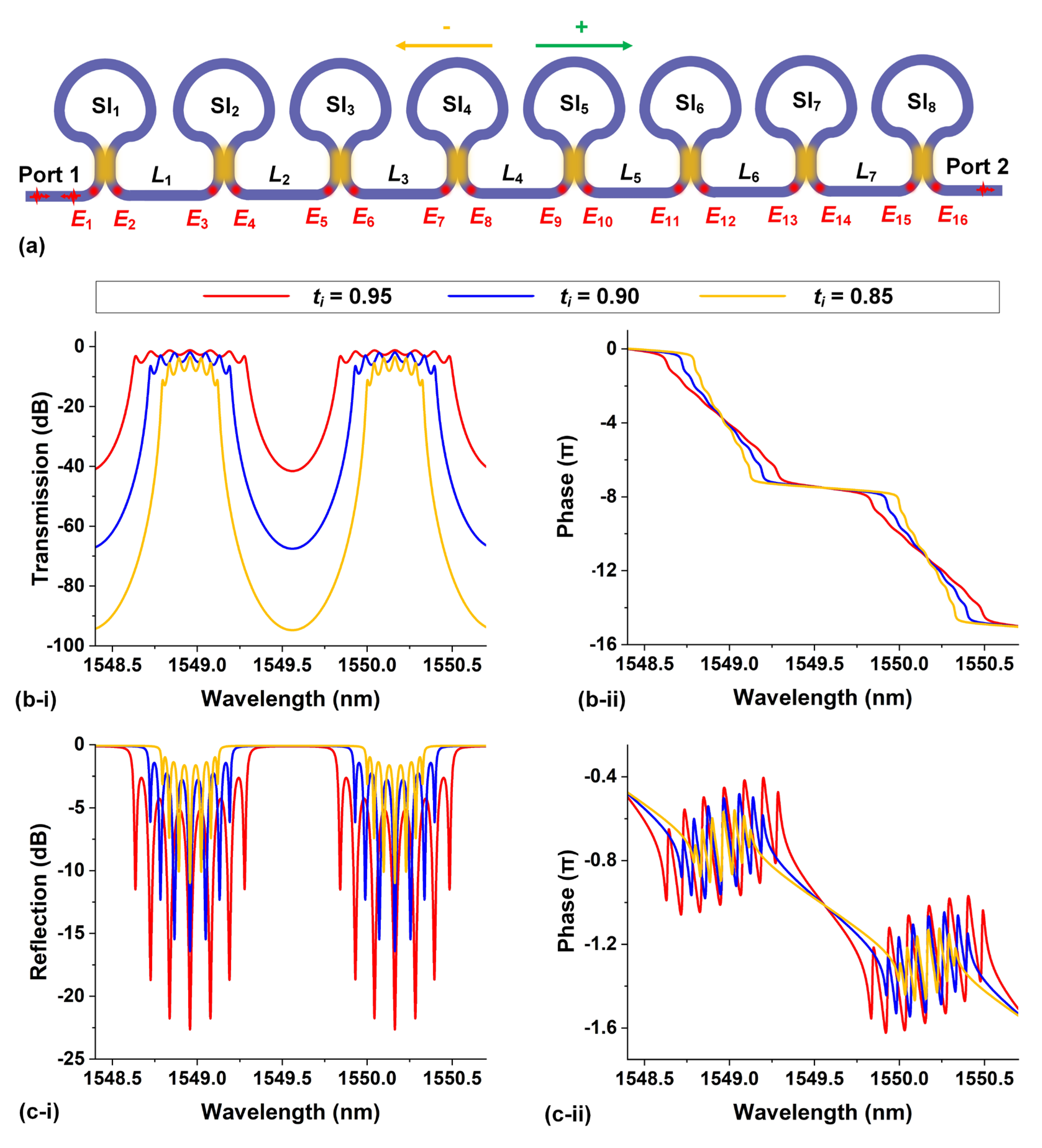
In Figure 5, we model a more complex device by dividing it into eight SIs and establishing 32 linear equations, as summarized in Table 5. The forward and backward field transfer functions for the SIs are denoted as TSI-i and RSI-i (i = 1 ‒ 8), respectively. Dividing the device into basic elements would result in a system of 64 equations, compared to the 32 equations shown in Table 5. By solving the system of 32 equations to obtain E16+ and E1, we obtain the spectral transfer functions at Port 2 and Port 1 (reflection), respectively. The corresponding response spectra are plotted in Figure 5(b) and Figure 5(c), which are consistent with the results in Ref. [95] and further confirms the effectiveness of our method in modeling devices with complex configurations.
When dividing complex devices into submodules, it’s important to ensure that the submodules are independent. Here, "independent" means that the submodules exchange energy with other parts exclusively through connecting waveguides. For the device shown in Figure 6a formed by a self-coupled waveguide, even though there are multiple SIs within the device, it cannot be divided into submodules of SIs. This is because the adjacent SIs are mutually coupled with energy exchange through directional couplers. In this case, the spectral transfer functions can be obtained by using the universal dividing method, which divides the device into basic elements of directional couplers and connecting waveguides.
Table 6 shows a system of 56 equations obtained by using the universal dividing method for the device in Figure 6a. By solving these equations to obtain E28+ and E1, we obtain the spectral transfer functions at Port 1 and Port 2, respectively. The corresponding response spectra for different ti are shown in Figure 6(b) and Figure 6(c). Except for ti, all other structural parameters are kept constant as: L1 = 180 μm, L2 = 60 μm and L3 = 120 μm. The response spectra also show a good agreement with the results in Ref. [24], providing additional evidence of the effectiveness of our method.

5. Deviations Induced by Approximations

As evidenced by the results in previous sections, our method proves effective for modeling integrated photonic resonators and shows advantages for modeling those with complex configurations. Despite this, the method still has limitations that could cause deviations between the simulation results and measurements for practical devices. In this section, we discuss the limitations of our method to model integrated photonic resonators and methods for improving modeling accuracy.
In our modeling, we assume the self-coupling coefficient t and cross-coupling coefficient κ of the directional couplers to be wavelength-independent constant, while this holds true only within a certain wavelength range. According to Ref. 34 95 32], the field cross-coupling coefficient κ of a directional coupler with a coupling length of Lc can be given by
κ = sin π 2 · L c L x ,
where Lx is the cross-over length, defined as the minimum distance at which optical power completely transfers from one waveguide to the other. The Lx can be further expressed as [95]
L x = λ 2 ( n eff ,   even - n eff ,   odd ) .
where λ is the light wavelength, neff, even and neff, odd are the effective indices of the two fundamental eigenmodes of the coupled waveguides, respectively. From Eqs. (7) and (8), it can be seen that the coupling strength of the directional coupler is actually wavelength dependent due to the existence of dispersion (which leads to wavelength-dependent values of neff, even and neff, odd). Therefore, the variation in the coupling strength of the directional couplers with wavelength can no longer be ignored when modeling the device’s response spectra over a broad bandwidth (typically > 30 nm).
Another potential limitation arises from the fact that we use a constant waveguide group index ng instead of wavelength-dependent waveguide effective index neff when calculating the phase shift along waveguides. In fact, the relation between ng and neff can be expressed as [94]:
n g = n eff ( λ ) -   λ d n eff ( λ ) d λ ,
where neff (λ) is the effective index as a function of light wavelength λ. The group index ng is widely used for calculating the free spectral ranges (FSRs) of integrated photonic resonators. For example, the FSR for a MRR can be approximately given by [94]
λ F SR     λ 0 2 n g L
where λ0 is the resonance wavelength and L is the ring circumference.
Similar to the cross-coupling coefficient κ of a directional coupler, the group index ng can be regarded as a constant coefficient only within a specific wavelength range. In contrast to introducing neff at different wavelengths, using a constant ng can greatly simplify the plotting of the response spectra based on the spectral transfer function. However, this approximation only holds for modeling spectral response over a relatively narrow wavelength range (e.g., < 30 nm). When modeling the spectral response over a broad bandwidth or for nonlinear optical devices that are sensitive to dispersion-induced phase mismatch [8,96,97,98,99,100,101,102,103,104,105,106,107,108,109,110,111,112,113,114,115,116,117,118,119,120,121,122,123,124,125,126,127,128], the wavelength-dependent neff should be used to achieve more accurate simulation results.

6. Conclusion

In summary, a universal approach for modeling integrated photonic resonators with complex structures is proposed based on the SMM. By dividing the device configuration into basic elements such as directional couplers and connecting waveguides, our approach shows effectiveness in modeling integrated photonic resonators with both unidirectional and bidirectional light propagation, with the simulated spectral response agreeing well with experimental results. By dividing the device configuration into independent submodules MRRs and SIs, the modeling in our approach can also be simplified. Finally, we discuss the limitations arising from approximations in our modeling and the corresponding strategies for improving modeling accuracy. Our approach offers an efficient way for designing and optimizing complex integrated photonic devices, which is applicable across a wide range of integrated platforms.

Conflicts of Interest

The authors declare no conflicts of interest.

References

  1. Xu, Q.; Schmidt, B.; Pradhan, S.; Lipson, M. Micrometre-scale silicon electro-optic modulator. Nature 2005, 435, 325–327. [Google Scholar] [CrossRef] [PubMed]
  2. Marin-Palomo, P.; Kemal, J.N.; Karpov, M.; Kordts, A.; Pfeifle, J.; Pfeiffer, M.H.P.; Trocha, P.; Wolf, S.; Brasch, V.; Anderson, M.H.; Rosenberger, R.; Vijayan, K.; Freude, W.; Kippenberg, T.J.; Koos, C. Microresonator-based solitons for massively parallel coherent optical communications. Nature 2017, 546, 274–279. [Google Scholar] [CrossRef]
  3. Schuler, S.; Muench, J.E.; Ruocco, A.; Balci, O.; Thourhout, D.V.; Sorianello, V.; Romagnoli, M.; Watanabe, K.; Taniguchi, T.; Goykhman, I.; Ferrari, A.C.; Mueller, T. High-responsivity graphene photodetectors integrated on silicon microring resonators. Nature Communications 2021, 12, 3733. [Google Scholar] [CrossRef] [PubMed]
  4. Liu, W.; Li, M.; Guzzon, R.S.; Norberg, E.J.; Parker, J.S.; Lu, M.; Coldren, L.A.; Yao, J. A fully reconfigurable photonic integrated signal processor. Nature Photonics 2016, 10, 190–195. [Google Scholar] [CrossRef]
  5. Wu, J.; Cao, P.; Hu, X.; Jiang, X.; Pan, T.; Yang, Y.; Qiu, C.; Tremblay, C.; Su, Y. Compact tunable silicon photonic differential-equation solver for general linear time-invariant systems. Optics Express 2014, 22, 26254–26264. [Google Scholar] [CrossRef] [PubMed]
  6. Wu, J.; Liu, B.; Peng, J.; Mao, J.; Jiang, X.; Qiu, C.; Tremblay, C.; Su, Y. On-chip tunable second-order differential-equation solver based on a silicon photonic mode-split microresonator. Journal of Lightwave Technology 2015, 33, 3542–3549. [Google Scholar] [CrossRef]
  7. Kippenberg, T.J.; Holzwarth, R.; Diddams, S.A. Microresonator-based optical frequency combs. Science 2011, 332, 555–559. [Google Scholar] [CrossRef] [PubMed]
  8. Wu, J.; Yang, Y.; Qu, Y.; Jia, L.; Zhang, Y.; Xu, X.; Chu, S.T.; Little, B.E.; Morandotti, R.; Jia, B.; Moss, D.J. 2D layered graphene oxide films integrated with micro-ring resonators for enhanced nonlinear optics. Small 2020, 16, 1906563. [Google Scholar] [CrossRef]
  9. Guarino, A.; Poberaj, G.; Rezzonico, D.; Degl, R.; Günter, P. Electro–optically tunable microring resonators in lithium niobate. Nature Photonics 2007, 1, 407–410. [Google Scholar] [CrossRef]
  10. Zheng, S.N.; Zou, J.; Cai, H.; Song, J.F.; Chin, L.K.; Liu, P.Y.; Lin, Z.P.; Kwong, D.L.; Liu, A.Q. Microring resonator-assisted Fourier transform spectrometer with enhanced resolution and large bandwidth in single chip solution. Nature Communications 2019, 10, 2349. [Google Scholar] [CrossRef] [PubMed]
  11. Chung-Yen, C.; Fung, W.; Guo, L.J. Polymer microring resonators for biochemical sensing applications. IEEE Journal of Selected Topics in Quantum Electronics 2006, 12, 134–142. [Google Scholar] [CrossRef]
  12. Khial, P.P.; White, A.D.; Hajimiri, A. Nanophotonic optical gyroscope with reciprocal sensitivity enhancement. Nature Photonics 2018, 12, 671–675. [Google Scholar] [CrossRef]
  13. Dong, B.; Brückerhoff-Plückelmann, F.; Meyer, L.; Dijkstra, J.; Bente, I.; Wendland, D.; Varri, A.; Aggarwal, S.; Farmakidis, N.; Wang, M.; Yang, G.; Lee, J.S.; He, Y.; Gooskens, E.; Kwong, D.-L.; Bienstman, P.; Pernice, W.H.P.; Bhaskaran, H. Partial coherence enhances parallelized photonic computing. Nature 2024, 632, 55–62. [Google Scholar] [CrossRef] [PubMed]
  14. Farmakidis, N.; Dong, B.; Bhaskaran, H. Integrated photonic neuromorphic computing: opportunities and challenges. Nature Reviews Electrical Engineering 2024, 1, 358–373. [Google Scholar] [CrossRef]
  15. Biasi, S.; Donati, G.; Lugnan, A.; Mancinelli, M.; Staffoli, E.; Pavesi, L. Photonic neural networks based on integrated silicon microresonators. Intelligent Computing, 3, 0067. [CrossRef]
  16. Yariv, A. Universal relations for coupling of optical power between microresonators and dielectric waveguides. Electronics Letters 2000, 36. [Google Scholar]
  17. Zhou, L.; Ye, T.; Chen, J. Coherent interference induced transparency in self-coupled optical waveguide-based resonators. Optics Letters 2011, 36, 13–15. [Google Scholar] [CrossRef] [PubMed]
  18. Souza, M.C.M.M.; Barea, L.A.M.; Vallini, F.; Rezende, G.F.M.; Wiederhecker, G.S.; Frateschi, N.C. Embedded coupled microrings with high-finesse and close-spaced resonances for optical signal processing. Optics Express 2014, 22, 10430–10438. [Google Scholar] [CrossRef] [PubMed]
  19. Arianfard, H.; Wu, J.; Juodkazis, S.; Moss, D.J. Three waveguide coupled Sagnac loop reflectors for advanced spectral engineering. Journal of Lightwave Technology 2021, 39, 3478–3487. [Google Scholar] [CrossRef]
  20. Arianfard, H.; Wu, J.; Juodkazis, S.; Moss, D.J. Advanced multi-functional integrated photonic filters based on coupled Sagnac loop reflectors. Journal of Lightwave Technology 2021, 39, 1400–1408. [Google Scholar] [CrossRef]
  21. Arianfard, H.; Wu, J.; Juodkazis, S.; Moss, D.J. Spectral shaping based on coupled Sagnac loop reflectors formed by a self-coupled wire waveguide. IEEE Photonics Technology Letters 2021, 33, 680–683. [Google Scholar] [CrossRef]
  22. Arianfard, H.; Wu, J.; Juodkazis, S.; Moss, D.J. Optical analogs of rabi splitting in integrated waveguide-coupled resonators. Advanced Physics Research 2023, 2, 2200123. [Google Scholar] [CrossRef]
  23. Arianfard, H.; Juodkazis, S.; Moss, D.J.; Wu, J. Sagnac interference in integrated photonics. Applied Physics Reviews 2023, 10, 011309. [Google Scholar] [CrossRef]
  24. Lai, S.; Xu, Z.; Liu, B.; Wu, J. Compact silicon photonic interleaver based on a self-coupled optical waveguide. Applied Optics 2016, 55, 7550–7555. [Google Scholar] [CrossRef] [PubMed]
  25. Wu, J.; Moein, T.; Xu, X.; Ren, G.; Mitchell, A.; Moss, D.J. Micro-ring resonator quality factor enhancement via an integrated Fabry-Perot cavity. APL Photonics 2017, 2, 056103. [Google Scholar] [CrossRef]
  26. Qiu, C.; Yu, P.; Hu, T.; Wang, F.; Jiang, X.; Yang, J. Asymmetric Fano resonance in eye-like microring system. Applied Physics Letters 2012, 101. [Google Scholar] [CrossRef]
  27. Moss, D.J.; Morandotti, R.; Gaeta, A.L.; Lipson, M. New CMOS-compatible platforms based on silicon nitride and Hydex for nonlinear optics. Nature Photonics 2013, 7, 597–607. [Google Scholar] [CrossRef]
  28. Poberaj, G.; Hu, H.; Sohler, W.; Günter, P. Lithium niobate on insulator (LNOI) for micro-photonic devices. Laser & Photonics Reviews 2012, 6, 488–503. [Google Scholar]
  29. Ferrera, M.; Razzari, L.; Duchesne, D.; Morandotti, R.; Yang, Z.; Liscidini, M.; Sipe, J.E.; Chu, S.; Little, B.E.; Moss, D.J. Low-power continuous-wave nonlinear optics in doped silica glass integrated waveguide structures. Nature Photonics 2008, 2, 737–740. [Google Scholar] [CrossRef]
  30. Qu, Y.; Wu, J.; Yang, Y.; Zhang, Y.; Liang, Y.; El Dirani, H.; Crochemore, R.; Demongodin, P.; Sciancalepore, C.; Grillet, C.; Monat, C.; Jia, B.; Moss, D.J. Enhanced four-wave mixing in silicon nitride waveguides integrated with 2D layered graphene oxide films. Advanced Optical Materials 2020, 8, 2001048. [Google Scholar] [CrossRef]
  31. Razzari, L.; et al. CMOS-compatible integrated optical hyper-parametric oscillator. Nature Photonics 2010, 4, 41–45. [Google Scholar] [CrossRef]
  32. Pasquazi, A.; et al. Sub-picosecond phase-sensitive optical pulse characterization on a chip. Nature Photonics 2011, 5, 618–623. [Google Scholar] [CrossRef]
  33. Ferrera, M.; et al. On-Chip ultra-fast 1st and 2nd order CMOS compatible all-optical integration. Optics Express 2011, 19, 23153–23161. [Google Scholar] [CrossRef] [PubMed]
  34. Bao, C.; et al. , Direct soliton generation in microresonators, Opt. Lett 2017, 42, 2519. [Google Scholar]
  35. Ferrera, M.; et al. CMOS compatible integrated all-optical RF spectrum analyzer. Optics Express 2014, 22, 21488–21498. [Google Scholar] [CrossRef] [PubMed]
  36. Kues, M.; et al. Passively modelocked laser with an ultra-narrow spectral width. Nature Photonics 2017, 11, 159. [Google Scholar] [CrossRef]
  37. Ferrera, M.; et al. “On-Chip ultra-fast 1st and 2nd order CMOS compatible all-optical integration. Opt. Express 2011, 19, 23153–23161. [Google Scholar] [CrossRef]
  38. Duchesne, D.; Peccianti, M.; Lamont, M.R.E.; et al. Supercontinuum generation in a high index doped silica glass spiral waveguide. Optics Express 2010, 18, 923–930. [Google Scholar] [CrossRef] [PubMed]
  39. Bao, H.; Olivieri, L.; Rowley, M.; Chu, S.T.; Little, B.E.; Morandotti, R.; Moss, D.J. , .. “Turing patterns in a fiber laser with a nested microresonator: Robust and controllable microcomb generation. Physical Review Research 2020, 2, 023395. [Google Scholar]
  40. Ferrera, M.; et al. On-chip CMOS-compatible all-optical integrator. Nature Communications 2010, 1, 29. [Google Scholar] [CrossRef] [PubMed]
  41. Pasquazi, A.; et al. All-optical wavelength conversion in an integrated ring resonator. Optics Express 2010, 18, 3858–3863. [Google Scholar] [CrossRef] [PubMed]
  42. Pasquazi, A.; Park, Y.; Azana, J.; et al. Efficient wavelength conversion and net parametric gain via Four Wave Mixing in a high index doped silica waveguide. Optics Express 2010, 18, 7634–7641. [Google Scholar] [CrossRef] [PubMed]
  43. Peccianti; Ferrera, M. ; Razzari, L.; et al. Subpicosecond optical pulse compression via an integrated nonlinear chirper. Optics Express 2010, 18, 7625–7633.
  44. Ferrera, M.; Park, Y.; Razzari, L.; Little, B.E.; Chu, S.T.; Morandotti, R.; Moss, D.J., ... et al. All-optical 1st and 2nd order integration on a chip. Optics Express 2011, 19, 23153–23161.
  45. Ferrera, M.; et al. Low Power CW Parametric Mixing in a Low Dispersion High Index Doped Silica Glass Micro-Ring Resonator with Q-factor > 1 Million. Optics Express 2009, 17, 14098–14103. [Google Scholar] [CrossRef] [PubMed]
  46. Peccianti, M.; et al. Demonstration of an ultrafast nonlinear microcavity modelocked laser. Nature Communications 2012, 3, 765. [Google Scholar] [CrossRef] [PubMed]
  47. Pasquazi, et al. Self-locked optical parametric oscillation in a CMOS compatible microring resonator: a route to robust optical frequency comb generation on a chip. Optics Express 2013, 21, 13333–13341. [CrossRef] [PubMed]
  48. Pasquazi, et al. Stable, dual mode, high repetition rate mode-locked laser based on a microring resonator. Optics Express 2012, 20, 27355–27362.
  49. Pasquazi, A.; et al. Micro-combs: a novel generation of optical sources. Physics Reports 2018, 729, 1–81. [Google Scholar] [CrossRef]
  50. Sun, Y.; Wu, J.; Tan, M.; Xu, X.; Li, Y. Roberto Morandotti, Arnan Mitchell, and David J. Moss, “Applications of optical micro-combs. Advances in Optics and Photonics 2023, 15, 86–175. [Google Scholar] [CrossRef]
  51. Bao, H.; et al. , Laser cavity-soliton microcombs. Nature Photonics 2019, 13, 384–389. [Google Scholar] [CrossRef]
  52. Cutrona, A.; Rowley, M.; Das, D.; Olivieri, L.; Peters, L.; Chu, S.T.; Little, B.L.; Morandotti, R.; Moss, D.J.; Gongora, J.S.T.; Peccianti, M.; Pasquazi, A. High Conversion Efficiency in Laser Cavity-Soliton Microcombs. Optics Express 2022, 30, 39816–39825. [Google Scholar] [CrossRef] [PubMed]
  53. M. Rowley; P.Hanzard; A.Cutrona; H.Bao; S.Chu; B.Little; R.Morandotti; Moss, D.J.; Oppo, G.; Gongora, J.; Peccianti, M.; Pasquazi, A. Self-emergence of robust solitons in a micro-cavity. Nature 2022, 608, 303–309.
  54. Cutrona, A.; Rowley, M.; Bendahmane, A.; Cecconi, V.; Olivieri, L.; Little, B.E.; Chu, S.T.; Stivala, S.; Morandotti, R.; Moss, D.J.; Totero-Gongora, J.S.; Peccianti, M.; Pasquazi, A. Nonlocal bonding of a soliton and a blue-detuned state in a microcomb laser. Nature Communications Physics 2023, 6, 259. [Google Scholar] [CrossRef]
  55. Rahim, A.A.; Alamgir, I.; Di Lauro, L.; Fischer, B.; Perron, N.; Dmitriev, P.; Mazoukh, C.; Roztocki, P.; Rimoldi, C.; Chemnitz, M.; Eshaghi, A.; Viktorov, E.A.; Kovalev, A.V.; Little, B.E.; Chu, S.T.; Moss, D.J.; Morandotti, R. Mode-locked laser with multiple timescales in a microresonator-based nested cavity. APL Photonics 2024, 9, 031302. [Google Scholar] [CrossRef]
  56. Cutrona, A.; Rowley, M.; Bendahmane, A.; Cecconi, V.; Olivieri, L.; Little, B.E.; Chu, S.T.; Stivala, S.; Morandotti, R.; Moss, D.J.; Totero-Gongora, J.S.; Peccianti, M.; Pasquazi, A. Stability Properties of Laser Cavity-Solitons for Metrological Applications. Applied Physics Letters 2023, 122, 121104. [Google Scholar] [CrossRef]
  57. Xu, X.; Wu, J.; Shoeiby, M.; Nguyen, T.G.; Chu, S.T.; Little, B.E.; Morandotti, R.; Mitchell, A.; Moss, D.J. Reconfigurable broadband microwave photonic intensity differentiator based on an integrated optical frequency comb source. APL Photonics 2017, 2, 096104. [Google Scholar] [CrossRef]
  58. Xu, X.; et al. Photonic microwave true time delays for phased array antennas using a 49 GHz FSR integrated micro-comb source. Photonics Research 2018, 6, B30–B36. [Google Scholar] [CrossRef]
  59. Xu, X.; Tan, M.; Wu, J.; Morandotti, R.; Mitchell, A.; Moss, D.J. Microcomb-based photonic RF signal processing. IEEE Photonics Technology Letters 2019, 31, 1854–1857. [Google Scholar] [CrossRef]
  60. Xu, et al. Advanced adaptive photonic RF filters with 80 taps based on an integrated optical micro-comb source. Journal of Lightwave Technology 2019, 37, 1288–1295.
  61. Xu, X.; et al. Photonic RF and microwave integrator with soliton crystal microcombs. IEEE Transactions on Circuits and Systems II: Express Briefs 2020, 67, 3582–3586. [Google Scholar] [CrossRef]
  62. Xu, X.; et al. High performance RF filters via bandwidth scaling with Kerr micro-combs. APL Photonics 2019, 4, 026102. [Google Scholar] [CrossRef]
  63. Tan, M.; et al. Microwave and RF photonic fractional Hilbert transformer based on a 50 GHz Kerr micro-comb. Journal of Lightwave Technology 2019, 37, 6097–6104. [Google Scholar] [CrossRef]
  64. Tan, M.; et al. RF and microwave fractional differentiator based on photonics. IEEE Transactions on Circuits and Systems: Express Briefs 2020, 67, 2767–2771. [Google Scholar] [CrossRef]
  65. Tan, M.; et al. Photonic RF arbitrary waveform generator based on a soliton crystal micro-comb source. Journal of Lightwave Technology 2020, 38, 6221–6226. [Google Scholar] [CrossRef]
  66. Tan, M.; Xu, X.; Wu, J.; Morandotti, R.; Mitchell, A.; Moss, D.J. RF and microwave high bandwidth signal processing based on Kerr Micro-combs. Advances in Physics X 2021, 6, 1838946. [Google Scholar] [CrossRef]
  67. Xu, X.; et al. Advanced RF and microwave functions based on an integrated optical frequency comb source. Opt. Express 2018, 26, 2569. [Google Scholar] [CrossRef]
  68. Tan, M.; Xu, X.; Wu, J.; Corcoran, B.; Boes, A.; Nguyen, T.G.; Chu, S.T.; Little, B.E.; Morandotti, R.; Lowery, A.; Mitchell, A.; Moss, D.J. "Highly Versatile Broadband RF Photonic Fractional Hilbert Transformer Based on a Kerr Soliton Crystal Microcomb. Journal of Lightwave Technology 2021, 39, 7581–7587. [Google Scholar] [CrossRef]
  69. Wu, J.; et al. RF Photonics: An Optical Microcombs’ Perspective. IEEE Journal of Selected Topics in Quantum Electronics 2018, 24, 6101020, 1-20. [Google Scholar] [CrossRef]
  70. Nguyen, T.G.; et al. Integrated frequency comb source-based Hilbert transformer for wideband microwave photonic phase analysis. Opt. Express 2015, 23, 22087–22097. [Google Scholar] [CrossRef] [PubMed]
  71. Xu, X.; et al. Broadband RF channelizer based on an integrated optical frequency Kerr comb source. Journal of Lightwave Technology 2018, 36, 4519–4526. [Google Scholar] [CrossRef]
  72. Xu, X.; et al. Continuously tunable orthogonally polarized RF optical single sideband generator based on micro-ring resonators. Journal of Optics 2018, 20, 115701. [Google Scholar] [CrossRef]
  73. Xu, X.; et al. Orthogonally polarized RF optical single sideband generation and dual-channel equalization based on an integrated microring resonator. Journal of Lightwave Technology 2018, 36, 4808–4818. [Google Scholar] [CrossRef]
  74. Xu, X.; et al. Photonic RF phase-encoded signal generation with a microcomb source. J. Lightwave Technology 2020, 38, 1722–1727. [Google Scholar] [CrossRef]
  75. Xu, X.; et al. Broadband microwave frequency conversion based on an integrated optical micro-comb source. Journal of Lightwave Technology 2020, 38, 332–338. [Google Scholar] [CrossRef]
  76. Tan, M.; et al. Photonic RF and microwave filters based on 49GHz and 200GHz Kerr microcombs. Optics Comm. 2020, 465, 125563. [Google Scholar] [CrossRef]
  77. Xu, X.; et al. Broadband photonic RF channelizer with 90 channels based on a soliton crystal microcomb. Journal of Lightwave Technology 2020, 38, 5116–5121. [Google Scholar] [CrossRef]
  78. Tan, M.; et al. Orthogonally polarized Photonic Radio Frequency single sideband generation with integrated micro-ring resonators. IOP Journal of Semiconductors 2021, 42, 041305. [Google Scholar] [CrossRef]
  79. Tan, M.; Xu, X.; Wu, J.; Nguyen, T.G.; Chu, S.T.; Little, B.E.; Morandotti, R.; Mitchell, A.; Moss, D.J. Photonic Radio Frequency Channelizers based on Kerr Optical Micro-combs. IOP Journal of Semiconductors 2021, 42, 041302. [Google Scholar] [CrossRef]
  80. Corcoran, B.; et al. Ultra-dense optical data transmission over standard fiber with a single chip source. Nature Communications 2020, 11, 2568. [Google Scholar] [CrossRef] [PubMed]
  81. Xu, X.; et al. Photonic perceptron based on a Kerr microcomb for scalable high speed optical neural networks. Laser and Photonics Reviews 2020, 14, 2000070. [Google Scholar] [CrossRef]
  82. Xu, X.; et al. 11 TOPs photonic convolutional accelerator for optical neural networks. Nature 2021, 589, 44–51. [Google Scholar] [CrossRef]
  83. X. ; Han; W.; Tan; M.; Sun; Y.; Li; Y.; Wu; J.; Morandotti; R.; Mitchell; A.; Xu; K.; Moss; D.J. Neuromorphic computing based on wavelength-division multiplexing. IEEE Journal of Selected Topics in Quantum Electronics 2023, 29, 7400112. [CrossRef]
  84. Bai, Y.; Xu, X.; Tan, M.; Sun, Y.; Li, Y.; Wu, J.; Morandotti, R.; Mitchell, A.; Xu, K.; Moss, D.J. Photonic multiplexing techniques for neuromorphic computing. Nanophotonics 2023, 12, 795–817. [Google Scholar] [CrossRef]
  85. Prayoonyong, C.; Boes, A.; Xu, X.; Tan, M.; Chu, S.T.; Little, B.E.; Morandotti, R.; Mitchell, A.; Moss, D.J.; Corcoran, B. Frequency comb distillation for optical superchannel transmission. Journal of Lightwave Technology 2021, 39, 7383–7392. [Google Scholar] [CrossRef]
  86. Tan, M.; Xu, X.; Wu, J.; Corcoran, B.; Boes, A.; Nguyen, T.G.; Chu, S.T.; Little, B.E.; Morandotti, R.; Mitchell, A.; Moss, D.J. Integral order photonic RF signal processors based on a soliton crystal micro-comb source. IOP Journal of Optics 2021, 23, 125701. [Google Scholar] [CrossRef]
  87. Sun, Y.; Wu, J.; Li, Y.; Xu, X.; Ren, G.; Tan, M.; Chu, S.T.; Little, B.E.; Morandotti, R.; Mitchell, A.; Moss, D.J. Optimizing the performance of microcomb based microwave photonic transversal signal processors. Journal of Lightwave Technology 2023, 41, 7223–7237. [Google Scholar] [CrossRef]
  88. Tan, M.; Xu, X.; Boes, A.; Corcoran, B.; Nguyen, T.G.; Chu, S.T.; Little, B.E.; Morandotti, R.; Wu, J.; Mitchell, A.; Moss, D.J. Photonic signal processor for real-time video image processing based on a Kerr microcomb. Communications Engineering 2023, 2, 94. [Google Scholar] [CrossRef]
  89. Tan, M.; Xu, X.; Wu, J.; Morandotti, R.; Mitchell, A.; Moss, D.J. Photonic RF and microwave filters based on 49GHz and 200GHz Kerr microcombs. Optics Communications 2020, 465, 125563. [Google Scholar] [CrossRef]
  90. Sun, Y.; Wu, J.; Li, Y.; Tan, M.; Xu, X.; Chu, S.; Little, B.; Morandotti, R.; Mitchell, A.; Moss, D.J. Quantifying the Accuracy of Microcomb-based Photonic RF Transversal Signal Processors. IEEE Journal of Selected Topics in Quantum Electronics 2023, 29, 1-17, 7500317. [Google Scholar] [CrossRef]
  91. Li, Y.; Sun, Y.; Wu, J.; Ren, G.; Corcoran, B.; Xu, X.; Chu, S.T.; Little, B.E.; Morandotti, R.; Mitchell, A.; Moss, D.J. Processing accuracy of microcomb-based microwave photonic signal processors for different input signal waveforms. MDPI Photonics 2023, 10, 10111283. [Google Scholar] [CrossRef]
  92. Murray, C.E.; Tan, M.; Prayoonyong, C.; Chu, S.T.; Little, B.E.; Morandotti, R.; Mitchell, A.; Moss, D.J.; Corcoran, B. Investigating the thermal robustness of soliton crystal microcombs. Optics Express 2023, 31, 37749–37762. [Google Scholar] [CrossRef]
  93. Sun, Y.; Wu, J.; Li, Y.; Moss, D.J. Comparison of microcomb-based RF photonic transversal signal processors implemented with discrete components versus integrated chips. MDPI Micromachines 2023, 14, 1794. [Google Scholar] [CrossRef]
  94. Bogaerts, W.; De Heyn, P.; Van Vaerenbergh, T.; De Vos, K.; Selvaraja, S.K.; Claes, T.; Dumon, P.; Bienstman, P.; Van Thourhout, D.; Baets, R. Silicon microring resonators. Laser & Photonics Reviews 2012, 6, 47–73. [Google Scholar]
  95. Chrostowski, L.; Hochberg, M. , Silicon photonics design: from devices to systems: Cambridge University Press. 2015. [Google Scholar]
  96. Qu, Y.; Wu, J.; Zhang, Y.; Yang, Y.; Jia, L.; Dirani, H.E.; Kerdiles, S.; Sciancalepore, C.; Demongodin, P.; Grillet, C.; Monat, C.; Jia, B.; Moss, D.J. Integrated optical parametric amplifiers in silicon nitride waveguides incorporated with 2D graphene oxide films. Light: Advanced Manufacturing 2023, 4, 1. [Google Scholar] [CrossRef]
  97. Wu, J.; et al. “2D layered graphene oxide films integrated with micro-ring resonators for enhanced nonlinear optics. Small 2020, 16, 1906563. [Google Scholar] [CrossRef]
  98. Wu, J.; et al. Graphene oxide waveguide and micro-ring resonator polarizers. Laser and Photonics Reviews 2019, 13, 1900056. [Google Scholar] [CrossRef]
  99. Zhang, Y.; et al. Enhanced Kerr nonlinearity and nonlinear figure of merit in silicon nanowires integrated with 2d graphene oxide films. ACS Applied Material Interfaces 2020, 12, 33094–33103. [Google Scholar] [CrossRef] [PubMed]
  100. Qu, Y.; et al. Enhanced four-wave mixing in silicon nitride waveguides integrated with 2d layered graphene oxide films. Advanced Optical Materials 2020, 8, 2001048. [Google Scholar] [CrossRef]
  101. Zhang, Y.; Wu, J.; Yang, Y.; Qu, Y.; Jia, L.; El Dirani, H.; Kerdiles, S.; Sciancalepore, C.; Demongodin, P.; Grillet, C.; Monat, C.; Jia, B.; Moss, D.J. Enhanced supercontinuum generated in SiN waveguides coated with GO films. Advanced Materials Technologies 2023, 8, 2201796. [Google Scholar] [CrossRef]
  102. Zhang, Y.; Wu, J.; Jia, L.; Qu, Y.; Jia, B.; Moss, D.J. Graphene oxide for nonlinear integrated photonics. Laser and Photonics Reviews 2023, 17, 2200512. [Google Scholar] [CrossRef]
  103. Wu, J. ; H. Lin; Moss, D.J.; Loh, T.K.; Jia, B. Graphene oxide for electronics, photonics, and optoelectronics. Nature Reviews Chemistry 2023, 7, 162–183. [Google Scholar] [CrossRef]
  104. Qu, Y.; Wu, J.; Zhang, Y.; Yang, Y.; Jia, L.; Jia, B.; Moss, D.J. Photo thermal tuning in GO-coated integrated waveguides. Micromachines 2022, 13, 1194. [Google Scholar] [CrossRef]
  105. Zhang, Y.; Wu, J.; Yang, Y.; Qu, Y.; El Dirani, H.; Crochemore, R.; Sciancalepore, C.; Demongodin, P.; Grillet, C.; Monat, C.; Jia, B.; Moss, D.J. Enhanced self-phase modulation in silicon nitride waveguides integrated with 2D graphene oxide films. IEEE Journal of Selected Topics in Quantum Electronics 2023, 29, 5100413. [Google Scholar] [CrossRef]
  106. Zhang, Y.; Wu, J.; Yang, Y.; Qu, Y.; Jia, L.; Jia, B.; Moss, D.J. Enhanced spectral broadening of femtosecond optical pulses in silicon nanowires integrated with 2D graphene oxide films. Micromachines 2022, 13, 756. [Google Scholar] [CrossRef]
  107. Wu, J.; Zhang, Y.; Hu, J.; Yang, Y.; Jin, D.; Liu, W.; Huang, D.; Jia, B.; Moss, D.J. Novel functionality with 2D graphene oxide films integrated on silicon photonic chips. Advanced Materials 2024, 36, 2403659. [Google Scholar] [CrossRef] [PubMed]
  108. Jin, D.; Wu, J.; Hu, J.; Liu, W.; Zhang, Y.; Yang, Y.; Jia, L.; Huang, D.; Jia, B.; Moss, D.J. Silicon photonic waveguide and microring resonator polarizers incorporating 2D graphene oxide films. Applied Physics Letters 2024, 125, 000000. [Google Scholar] [CrossRef]
  109. Zhang, Y.; Wu, J.; Jia, L.; Jin, D.; Jia, B.; Hu, X.; Moss, D.; Gong, Q. Advanced optical polarizers based on 2D materials. npj Nanophotonics 2024, 1. [Google Scholar] [CrossRef]
  110. Hu, J.; Wu, J.; Liu, W.; Jin, D.; El Dirani, H.; Kerdiles, S.; Sciancalepore, C.; Demongodin, P.; Grillet, C.; Monat, C.; Huang, D.; Jia, B.; Moss, D.J. 2D graphene oxide: a versatile thermo-optic material. Advanced Functional Materials 2024, 34, 2406799. [Google Scholar] [CrossRef]
  111. Qu, Y.; Wu, J.; Zhang, Y.; Yang, Y.; Jia, L.; El Dirani, H.; Kerdiles, S.; Sciancalepore, C.; Demongodin, P.; Grillet, C.; Monat, C.; Jia, B.; Moss, D.J. Integrated optical parametric amplifiers in silicon nitride waveguides incorporated with 2D graphene oxide films. Light: Advanced Manufacturing 2023, 4, 39. [Google Scholar] [CrossRef]
  112. Jin, D.; Liu, W.; Jia, L.; Hu, J.; Huang, D.; Wu, J.; Jia, B.; Moss, D.J. Thickness and Wavelength Dependent Nonlinear Optical Absorption in 2D Layered MXene Films. Small Science 2024, 4, 2400179. [Google Scholar] [CrossRef]
  113. Jia, L.; Wu, J.; Zhang, Y.; Qu, Y.; Jia, B.; Chen, Z.; Moss, D.J. Fabrication Technologies for the On-Chip Integration of 2D Materials. Small: Methods 2022, 6, 2101435. [Google Scholar] [CrossRef]
  114. Zhang, Y.; Wu, J.; Qu, Y.; Jia, L.; Jia, B.; Moss, D.J. Design and optimization of four-wave mixing in microring resonators integrated with 2D graphene oxide films. Journal of Lightwave Technology 2021, 39, 6553–6562. [Google Scholar] [CrossRef]
  115. Zhang, Y.; Wu, J.; Qu, Y.; Jia, L.; Jia, B.; Moss, D.J. Optimizing the Kerr nonlinear optical performance of silicon waveguides integrated with 2D graphene oxide films. Journal of Lightwave Technology 2021, 39, 4671–4683. [Google Scholar] [CrossRef]
  116. Qu, Y.; Wu, J.; Zhang, Y.; Liang, Y.; Jia, B.; Moss, D.J. Analysis of four-wave mixing in silicon nitride waveguides integrated with 2D layered graphene oxide films. Journal of Lightwave Technology 2021, 39, 2902–2910. [Google Scholar] [CrossRef]
  117. Wu, J.; Jia, L.; Zhang, Y.; Qu, Y.; Jia, B.; Moss, D.J. Graphene oxide: versatile films for flat optics to nonlinear photonic chips. Advanced Materials 2021, 33, 2006415, pp.1-29. [Google Scholar] [CrossRef]
  118. Qu, Y.; Wu, J.; Zhang, Y.; Jia, L.; Yang, Y.; Xu, X.; Chu, S.T.; Little, B.E.; Morandotti, R.; Jia, B.; Moss, D.J. Graphene oxide for enhanced optical nonlinear performance in CMOS compatible integrated devices. Paper No. 11688-30, PW21O-OE109-36, 2D Photonic Materials and Devices IV, SPIE Photonics West, San Francisco CA March 6-11 (2021). 2583. [Google Scholar]
  119. Qu, Y.; Wu, J.; Yang, Y.; Zhang, Y.; Liang, Y.; El Dirani, H.; Crochemore, R.; Demongodin, P.; Sciancalepore, C.; Grillet, C.; Monat, C.; Jia, B.; Moss, D.J. Enhanced nonlinear four-wave mixing in silicon nitride waveguides integrated with 2D layered graphene oxide films. Advanced Optical Materials 2020, 8, 2001048. [Google Scholar] [CrossRef]
  120. Zhang, Y.; Qu, Y.; Wu, J.; Jia, L.; Yang, Y.; Xu, X.; Jia, B.; Moss, D.J. Enhanced Kerr nonlinearity and nonlinear figure of merit in silicon nanowires integrated with 2D graphene oxide films. ACS Applied Materials and Interfaces 2020, 12, 33094–33103. [Google Scholar] [CrossRef] [PubMed]
  121. Wu, J.; Yang, Y.; Qu, Y.; Zhang, Y.; Jia, L.; Xu, X.; Chu, S.T.; Little, B.E.; Morandotti, R.; Jia, B.; Moss, D.J. Enhanced nonlinear four-wave mixing in microring resonators integrated with layered graphene oxide films. Small 2020, 16, 1906563. [Google Scholar] [CrossRef] [PubMed]
  122. Wu, J.; Yang, Y.; Qu, Y.; Xu, X.; Liang, Y.; Chu, S.T.; Little, B.E.; Morandotti, R.; Jia, B.; Moss, D.J. Graphene oxide waveguide polarizers and polarization selective micro-ring resonators. Paper 11282-29, SPIE Photonics West, San Francisco, CA, 4 - 7 February (2020). [CrossRef]
  123. Wu, J.; Yang, Y.; Qu, Y.; Xu, X.; Liang, Y.; Chu, S.T.; Little, B.E.; Morandotti, R.; Jia, B.; Moss, D.J. Graphene oxide waveguide polarizers and polarization selective micro-ring resonators. Laser and Photonics Reviews 2019, 13, 1900056. [Google Scholar] [CrossRef]
  124. Yang, Y.; Wu, J.; Xu, X.; Chu, S.T.; Little, B.E.; Morandotti, R.; Jia, B.; Moss, D.J. Enhanced four-wave mixing in graphene oxide coated waveguides. Applied Physics Letters Photonics 2018, 3, 120803. [Google Scholar] [CrossRef]
  125. Jia, L.; Qu, Y.; Wu, J.; Zhang, Y.; Yang, Y.; Jia, B.; Moss, D.J. Third-order optical nonlinearities of 2D materials at telecommunications wavelengths. Micromachines (MDPI) 2023, 14, 307. [Google Scholar] [CrossRef]
  126. Jia, L.; Cui, D.; Wu, J.; Feng, H.; Yang, T.; Yang, Y.; Du, Y.; Hao, W.; Jia, B.; Moss, D.J. BiOBr nanoflakes with strong nonlinear optical properties towards hybrid integrated photonic devices. Applied Physics Letters Photonics 2019, 4, 090802. [Google Scholar] [CrossRef]
  127. Jia, L.; Wu, J.; Yang, Y.; Du, Y.; Jia, B.; Moss, D.J. Large Third-Order Optical Kerr Nonlinearity in Nanometer-Thick PdSe2 2D Dichalcogenide Films: Implications for Nonlinear Photonic Devices. ACS Applied Nano Materials 2020, 3, 6876–6883. [Google Scholar] [CrossRef]
  128. Jin, D.; Liu, W.; Jia, L.; Zhang, Y.; Hu, J.; El Dirani, H.; Kerdiles, S. Sciancalepore, P. Demongodin, C. Grillet, C. Monat, D. Huang, J. Wu, B. Jia, and D. J. Moss, “Thickness- and wavelength-dependent nonlinear optical absorption in 2D layered MXene films. Small Science 2400179.
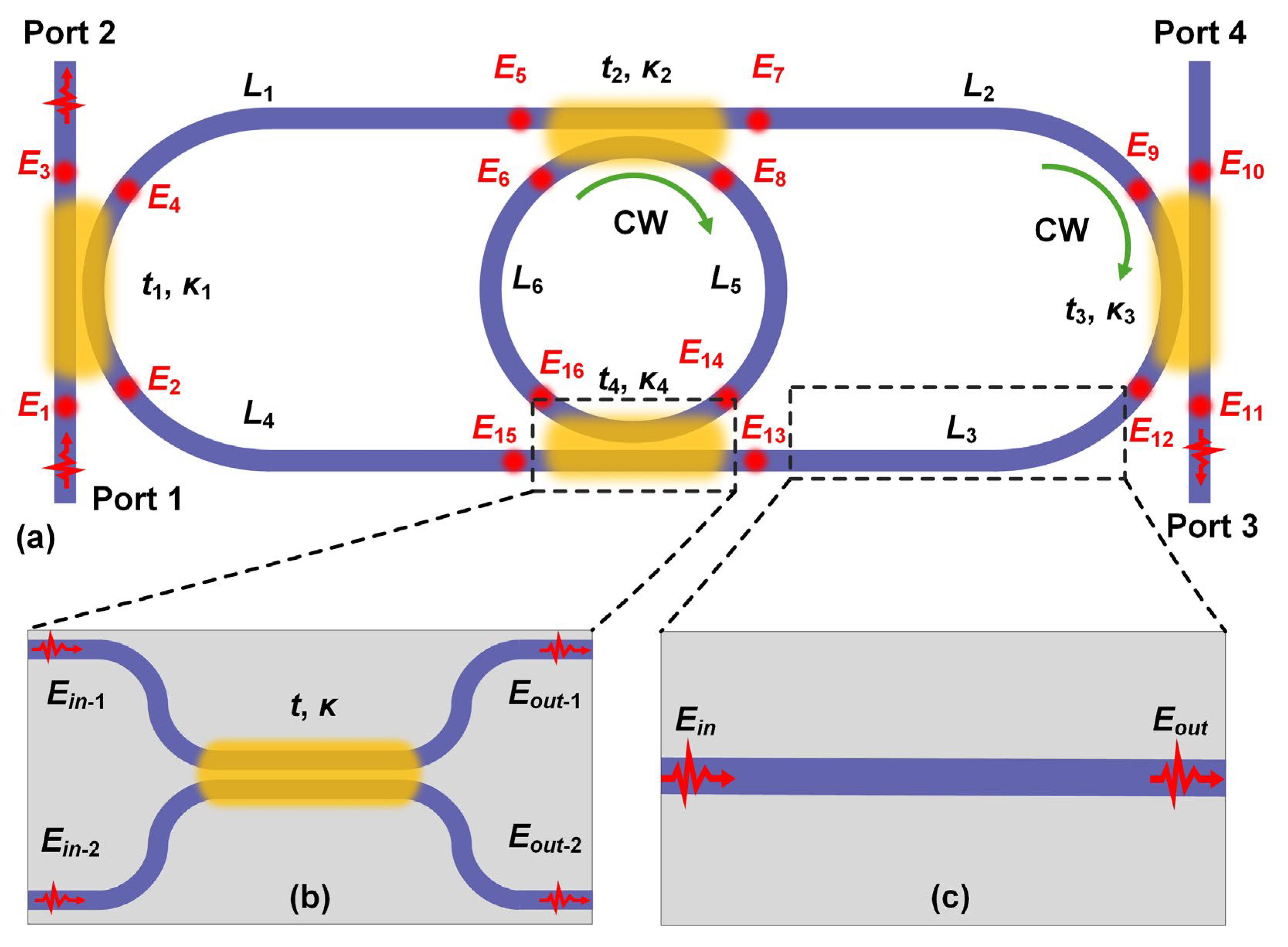
Figure 1. (a) Schematic illustration of an integrated photonic resonator consisting of two microring resonators (MRRs) with an input from Port 1. The device is divided into several directional couplers and connecting waveguides, with Ei (i = 1–16) denoting the optical fields at the dividing points. (b) ‒ (c) zoom-in views for a directional coupler and a connecting waveguide, respectively.
Preprints 120310 g001
Figure 2. (a) Calculated (i) intensity and (ii) phase response spectra at Port 2 for the device in Figure 1 with different t1 = t3. (b) Calculated (i) intensity and (ii) phase response spectra at Port 3 for the device in Figure 1 with different t1 = t3. In (a) and (b), t2 = t4 = 0.98. The power propagation loss factor α and group index ng are assumed to be 101 m-1 and 4.335, respectively.
Preprints 120310 g002
Figure 3. (a) Schematic illustration of an integrated photonic resonator formed by an add-drop micro-ring resonator (AD-MRR) sandwiched between two Sagnac interferometers (SIs) with an input from Port 1. The device is divided into several directional couplers and connecting waveguides, with Ei (i = 1–16) denoting the optical fields at the dividing points. The electric fields propagating from left to right are defined as “+” direction and the ones propagating from right to left are defined as “–” direction. (b) Calculated (i) power transmission and (ii) phase response spectra at Port 2 for different t1 = t4. (c) Calculated (i) power reflection and (ii) phase response spectra at Port 1 for different t1 = t4.
Preprints 120310 g003
Figure 4. Dividing device configuration into submodules to simplify the calculation (a) Device configuration in Figure 1(a), where the add-drop micro-ring resonator (AD-MRR) at the center is regarded as an independent module. (b) Device configuration in Figure 3(a), which is divided into submodules including an AD-MRR, two Sagnac interferometers (SIs), and connecting waveguides between them.
Preprints 120310 g004
Figure 5. (a) Schematic illustration of an integrated photonic resonator formed by eight cascaded Sagnac interferometers (SIs) with input from Port 1. The device is divided into eight SIs and connecting waveguides between them, with Ei (i = 1–16) denoting the optical fields at the dividing points. The electric fields propagating from to right to left are defined as “+” direction and the ones propagating from left to right are defined as “–” direction. (b) Calculated (i) power transmission and (ii) phase response spectra at Port 2 for different ti (i = 1–8), which are the are the self-coupling coefficients of the directional couplers in SIs. (c) Calculated (i) power reflection and (ii) phase response spectra at Port 1 for different ti (i = 1–8). In (b) and (c), the circumference of the rings in the SIs are 129.66 μm, and the lengths of the connecting waveguides between them are 100 μm.
Preprints 120310 g005
Figure 6. (a) Schematic illustration of an integrated photonic resonator formed by a self-coupled waveguide with input from Port 1. The device is divided into several directional couplers and connecting waveguides, with Ei (i = 1–28) denoting the optical fields at the dividing points. The electric fields propagating from to up to down are defined as “+” direction and the ones propagating from down to up are defined as “–” direction. (b) Calculated (i) power transmission and (ii) phase response spectra at Port 2 for different ti, which are the are the self-coupling coefficients of the directional couplers. (c) Calculated (i) power reflection and (ii) phase response spectra at Port 1 for different ti.
Preprints 120310 g006
Table 1. Definitions of structural parameters of the device in Figure 1(a) and the corresponding scattering matrix equations.
Directional
couplers
Structural
Parameters
(i = 1 – 4)
Field transmission
coefficient
Field cross coupling
coefficient
ti κi
Scattering
matrix
equations
E 3 E 4   =   t 1 j κ 1 j κ 1 t 1 E 1 E 2 , E 7 E 8 = t 2 j κ 2 j κ 2 t 2 E 5 E 6 ,  
E 12 E 11 = t 3 j κ 3 j κ 3 t 3 E 9 E 10 ,   E 15 E 16 = t 4 j κ 4 j κ 4 t 4 E 13 E 14 .
Connecting
waveguides
Structural
Parameters
(i = 1 – 6)
Length Transmission factor Phase shift
Li ai φi
Scattering
matrix
equations
E5 = T1E4, E9 = T2E7, E13 = T3E12,
E2 = T4E15, E14 = T5E8, E6 = T6E16.
Input E1 = 1, E10 = 0.
Table 2. Definitions of structural parameters of the device in Figure 3(a) and the corresponding scattering matrix equations.
Directional
couplers
Structural
Parameters
(i = 1 – 4)
Field transmission coefficient Field cross coupling coefficient
ti κi
Scattering
matrix
equations
E 2 + E 3 -   =   t 1 j κ 1 j κ 1 t 1 E 1 + E 4 - , E 1 - E 4 +   =   t 1 j κ 1 j κ 1 t 1 E 2 - E 3 + ,
E 7 + E 8 + = t 2 j κ 2 j κ 2 t 2 E 5 + E 6 + ,   E 5 - E 6 - = t 2 j κ 2 j κ 2 t 2 E 7 - E 8 - ,
E 11 + E 12 + = t 3 j κ 3 j κ 3 t 3 E 9 + E 10 + ,   E 9 - E 10 - = t 3 j κ 3 j κ 3 t 3 E 11 - E 12 - ,
E 14 + E 15 - = t 4 j κ 4 j κ 4 t 4 E 13 + E 16 - ,   E 13 - E 16 + = t 4 j κ 4 j κ 4 t 4 E 14 - E 15 + .
Connecting
waveguides
Structural
Parameters
(i = 1 – 6)
Length Transmission factor Phase shift
Li ai φi
Scattering
matrix
equations
E 3 + E 2 - = T 1 E 2 + E 3 - , E 5 + E 4 - = T 2 E 4 + E 5 - , E 9 + E 8 - = T 3 E 8 + E 9 - ,
E 6 + E 11 - = T 4 E 11 + E 6 - , E 13 + E 12 - = T 5 E 12 + E 13 - , E 15 + E 14 - = T 6 E 14 + E 15 - .
Input E1+ = 1, E7− = 0, E10 + = 0, E16− = 0.
Table 3. Scattering matrix equations for the device in Figure 4(a). TRR and DRR are the field transfer functions at the through and drop ports for the AD-MRR, respectively.
Scattering
matrix
equations
Add-drop micro-ring
resonator (AD-MRR)
E 6 E 12   =   T RR D RR D RR T RR E 5 E 11 .
Directional couplers E 3 E 4   =   t 1 j κ 1 j κ 1 t 1 E 1 E 2 , E 10 E 9 = t 2 j κ 2 j κ 2 t 2 E 7 E 8 .
Connecting
waveguides
E5 = Tw1E4, E7 = Tw2E6, E11 = Tw3E10, E2 = Tw4E12.
Input E1 = 1, E8 = 0.
Table 4. Scattering matrix equations for the device in Figure 4(b). TSI-i and RSI-i (i = 1, 2) are forward and backward field transfer functions for the SIs, respectively. TRR and DRR are the field transfer functions at the through and drop ports for the AD-MRR, respectively.
Scattering
matrix
equations
Sagnac
interferometers (SIs)
E 2 + E 1 - = T SI - 1 R SI - 1 R SI - 1 T SI - 1 E 1 + E 2 - , E 6 + E 5 - = T SI - 2 R SI - 2 R SI - 2 T SI - 2 E 5 + E 6 - .
Add-drop micro-ring
resonator (AD-MRR)
E 4 + E 3 - = D RR E 3 + E 4 - .
Connecting
waveguides
E 3 + E 2 - = T w 1 E 2 + E 3 - , E 5 + E 4 - = T w 2 E 4 + E 5 - .
Input E1+ = 1, E6− = 0.
Table 5. Scattering matrix equations for the device in Figure 5(a). TSI-i and RSI-i (i = 1 ‒ 8) are the forward and backward field transfer functions for the SIs, respectively.
Scattering
matrix
equations
Sagnac
interferometers (SIs)
E 2 + E 1 - = T SI - 1 R SI - 1 R SI - 1 T SI - 1 E 1 + E 2 - ,   E 4 + E 3 - = T SI - 2 R SI - 2 R SI - 2 T SI - 2 ,
E 6 + E 5 - = T SI - 3 R SI - 3 R SI - 3 T SI - 3 E 5 + E 6 - ,   E 8 + E 7 - = T SI - 4 R SI - 4 R SI - 4 T SI - 4 E 7 + E 8 - ,
E 10 + E 9 - = T SI - 5 R SI - 5 R SI - 5 T SI - 5 E 9 + E 10 - ,   E 12 + E 11 - = T SI - 6 R SI - 6 R SI - 6 T SI - 6 E 11 + E 12 - ,
E 14 + E 13 - = T SI - 7 R SI - 7 R SI - 7 T SI - 7 E 13 + E 14 - ,   E 16 + E 15 - = T SI - 8 R SI - 8 R SI - 8 T SI - 8 E 15 + E 16 - .
Connecting
waveguides
E 3 + E 2 - = T w 1 E 2 + E 3 - , E 5 + E 4 - = T w 2 E 4 + E 5 - , E 7 + E 6 - = T w 3 E 6 + E 7 - ,
E 9 + E 8 - = T w 4 E 8 + E 9 - ,   E 11 + E 10 - = T w 5 E 10 + E 11 - ,   E 13 + E 12 - = T w 6 E 12 + E 13 - ,
E 15 + E 14 - = T w 7 E 14 + E 15 - .
Input E16+ = 1, E1− = 0.
Table 6. Definitions of structural parameters of the device in Figure 6(a) and the corresponding scattering matrix equations.
Directional
couplers
Structural
Parameters
(i = 1 – 7)
Field transmission coefficient Field cross coupling coefficient
ti κi
Scattering
matrix
equations
E 2 + E 5 -   =   t 1 j κ 1 j κ 1 t 1 E 1 + E 6 - , E 1 - E 6 +   =   t 1 j κ 1 j κ 1 t 1 E 2 - E 5 + ,
E 4 + E 9 - = t 2 j κ 2 j κ 2 t 2 E 3 + E 10 - ,   E 3 - E 10 + = t 2 j κ 2 j κ 2 t 2 E 4 - E 9 + ,  
E 8 + E 13 - = t 3 j κ 3 j κ 3 t 3 E 7 + E 14 - ,   E 7 - E 14 + = t 3 j κ 3 j κ 3 t 3 E 8 - E 13 + ,
E 12 + E 17 - = t 4 j κ 4 j κ 4 t 4 E 11 + E 18 - ,   E 18 - E 11 + = t 4 j κ 4 j κ 4 t 4 E 12 - E 17 + ,
E 16 + E 21 - = t 5 j κ 5 j κ 5 t 5 E 15 + E 22 - ,   E 15 - E 22 + = t 5 j κ 5 j κ 5 t 5 E 16 - E 21 + ,
E 20 + E 25 - = t 6 j κ 6 j κ 6 t 6 E 19 + E 26 - ,   E 19 - E 26 + = t 6 j κ 6 j κ 6 t 6 E 20 - E 25 + ,
E 24 + E 27 - = t 7 j κ 7 j κ 7 t 7 E 23 + E 28 - ,   E 23 - E 28 + = t 7 j κ 7 j κ 7 t 7 E 24 - E 27 + .
Connecting
waveguides
Structural
Parameters
(i = 1 – 3)
Length Transmission factor Phase shift
Li ai φi
Scattering
matrix
equations
E 3 + E 2 - = T 1 E 2 + E 3 - , E 5 + E 4 - = T 2 E 4 + E 5 - , E 7 + E 6 - = T 3 E 6 + E 7 - , E 9 + E 8 - = T 2 E 8 + E 9 - ,
E 11 + E 10 - = T 3 E 10 + E 11 - , E 13 + E 12 - = T 2 E 12 + E 13 - , E 15 + E 14 - = T 3 E 14 + E 15 - , E 17 + E 16 - = T 2 E 16 + E 17 - , E 19 + E 18 - = T 3 E 18 + E 19 - , E 21 + E 20 - = T 2 E 20 + E 21 - ,
E 23 + E 22 - = T 3 E 22 + E 23 - , E 25 + E 24 - = T 2 E 24 + E 25 - , E 27 + E 26 - = T 1 E 26 + E 27 - .
Input E1+ = 1, E28− = 0.
Disclaimer/Publisher’s Note: The statements, opinions and data contained in all publications are solely those of the individual author(s) and contributor(s) and not of MDPI and/or the editor(s). MDPI and/or the editor(s) disclaim responsibility for any injury to people or property resulting from any ideas, methods, instructions or products referred to in the content.
Copyright: This open access article is published under a Creative Commons CC BY 4.0 license, which permit the free download, distribution, and reuse, provided that the author and preprint are cited in any reuse.
Prerpints.org logo

Preprints.org is a free preprint server supported by MDPI in Basel, Switzerland.

Subscribe

© 2024 MDPI (Basel, Switzerland) unless otherwise stated