1. Introduction
The ever-growing accumulation of space debris—comprising defunct satellites, discarded rocket stages, and fragments from past collisions or explosions—poses an escalating threat to the safety and sustainability of current and future space operations. As of May 2022, there were over 130 million pieces of debris larger than 1 mm in Earth’s orbit. Research indicates that the debris population in low Earth orbit (LEO) is unstable and will continue to grow, even without new launches, due to collisions between existing debris. To maintain a sustainable LEO environment, the removal of at least five large debris objects annually is deemed essential. Active debris removal (ADR) has thus become a critical focus for space agencies, with several methods being explored, including robotic arms, flying nets, tethers, harpoons, lasers, ion beam shepherds, and electrodynamic tethers.
A major challenge in ADR is the detumbling of space debris, which often rotates or tumbles due to residual angular momentum and space disturbances. Tumbling debris complicates capture and deorbit operations, leading to potential risks such as entanglement of tether systems or damage to robotic arms. To address this, a variety of detumbling techniques have been proposed, ranging from biologically inspired mechanisms like gecko adhesive grippers and soft tentacles to methods utilizing magnetic eddy currents and thruster plume impingement. Despite their promise, these methods face significant limitations. For example, contact-based methods often result in debris moving away from the detumbling equipment due to reactive forces, necessitating frequent positional adjustments by the servicing satellite, which increases fuel consumption and reduces operational life. Furthermore, most existing methods require large and complex systems, making them dependent on major space agencies and expensive to implement.
To overcome these challenges, a novel nanosatellite-based detumbling approach is proposed, utilizing adhesion and harpoon-based mechanisms. Unlike conventional methods, this strategy employs a nanosatellite equipped with multiple harpoons and thrusters. Deployed from a servicing satellite, the nanosatellite attaches itself to the debris by embedding harpoons into the target’s surface. This robust attachment allows the nanosatellite’s thrusters to detumble the debris effectively without the risk of drifting away. The harpoon-based attachment method also avoids generating new debris, as tests have shown that any fragments created remain contained within the target.
In this study, we build on previous work by developing a high-fidelity dynamic model for the combined system of the nanosatellite and the debris object. This model accounts for coupled orbital and attitude dynamics during the detumbling process, incorporating factors such as atmospheric drag, gravity-gradient torques, and variations in inertial parameters due to fuel consumption. An adaptive sliding mode control scheme, integrated with pulse-width pulse-frequency (PWPF) modulation, is proposed to handle uncertainties in the model and ensure robust control of the debris object. Unlike previous approaches, this method does not require precise knowledge of the debris’ inertial parameters, making it highly effective for detumbling operations without extensive prior assessment.
The remainder of this paper is structured as follows:
Section 2 provides an overview of the dynamic model and preliminary considerations;
Section 3 details the collision modeling between the detumbling device and debris;
Section 4 derives the coupled orbit-attitude dynamics of the system;
Section 5 introduces the adaptive sliding mode control approach;
Section 6 presents simulation results demonstrating the effectiveness of the proposed strategy; and
Section 7 concludes with a discussion of the findings and future work.
2. Preliminaries
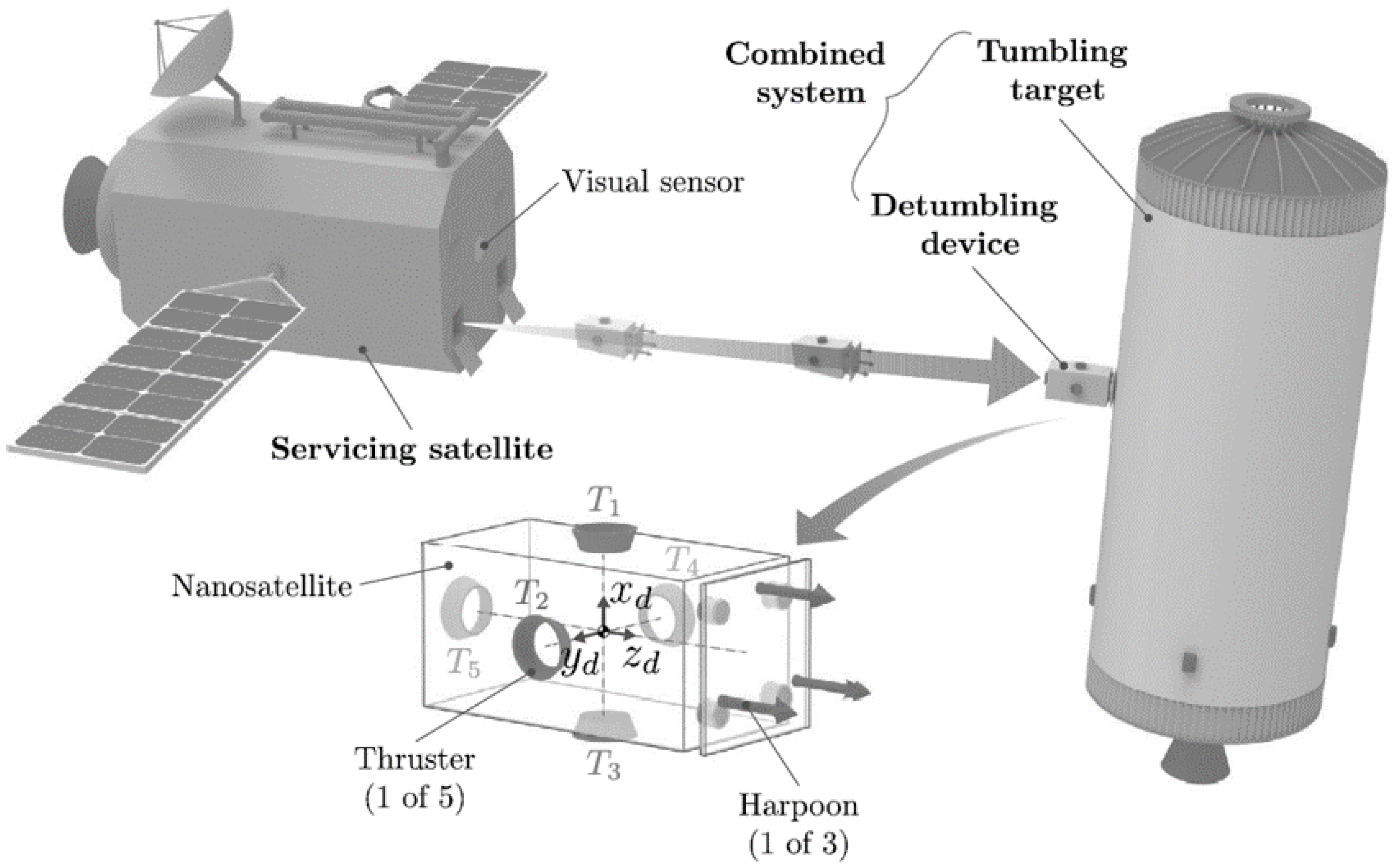
Figure 1.
An example of the adhesion detumbling approach based on harpoons.
Figure 1.
An example of the adhesion detumbling approach based on harpoons.
2.1. System Overview and Reference Frames
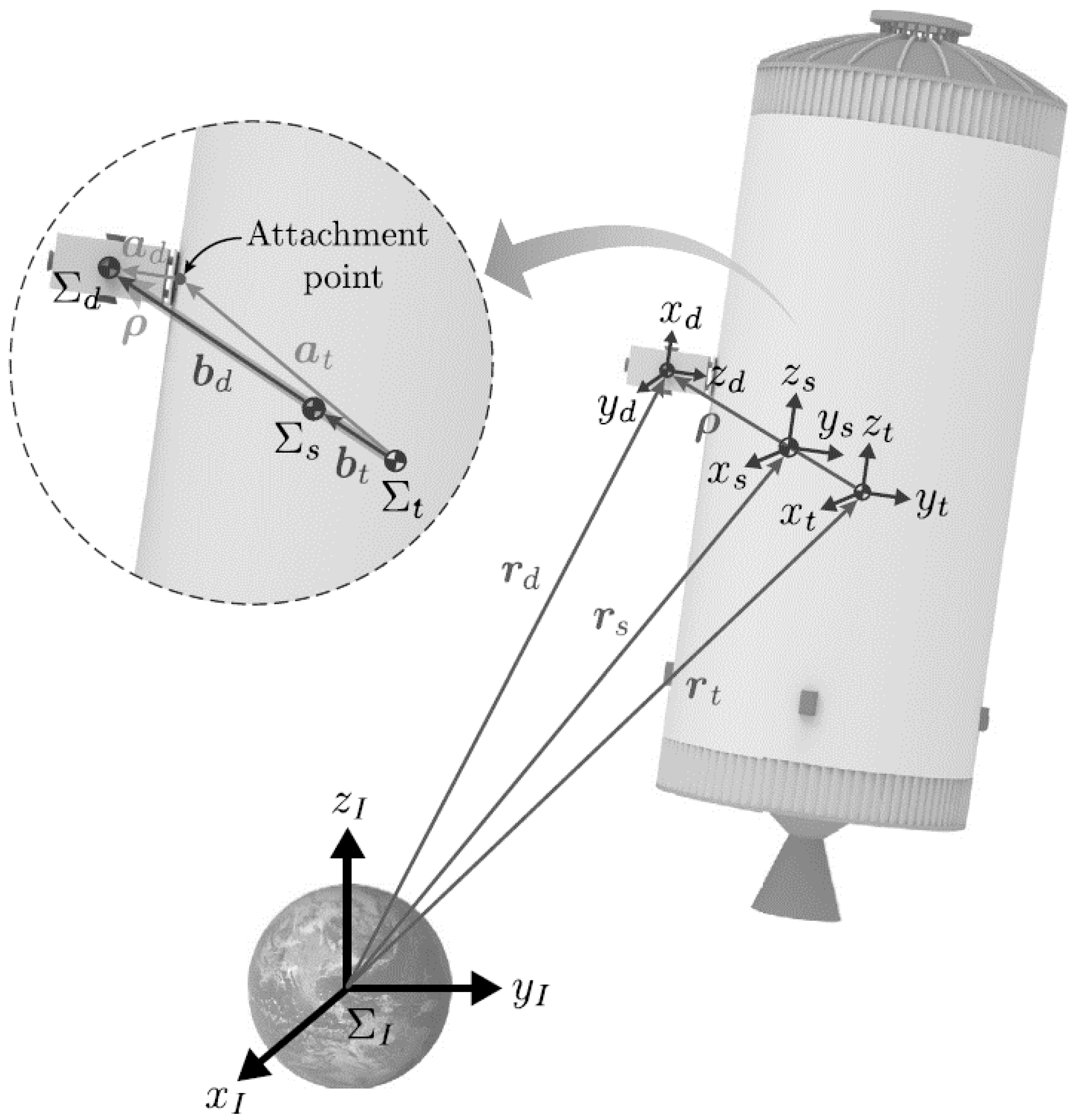
This study presents a detumbling strategy for stabilizing tumbling space debris, such as a rocket upper stage in low Earth orbit (LEO). The proposed method involves a detumbling device that secures itself to the debris by embedding multiple harpoons into its surface, creating a single, rigid system. The dynamics of this system are described using several reference frames:
Inertial Frame (): A fixed frame centered at Earth’s center, used for describing orbital motion.
Target Frame (): Attached to the center of mass (CoM) of the debris, describing its rotation.
Device Frame (): Attached to the detumbling device’s CoM, used for thruster control.
Combined System Frame (): Represents the newly formed system after attachment, aligned with the target frame.
The detumbling device is equipped with thrusters oriented along specific axes of the device frame, enabling controlled maneuvers to reduce the debris’s angular velocity. For simplicity, both the device and debris are modeled as rigid bodies, and thruster operations are considered instantaneous and precise.
2.2. Notations
Figure 2.
Position vectors and reference frames for the combined system.
Figure 2.
Position vectors and reference frames for the combined system.
In this paper, various symbolic representations are used to describe vectors, matrices, and transformations between different reference frames. To ensure clarity, the key notations are defined as follows:
For any vector and matrix expressed in the inertial reference frame , their representations in another reference frame are denoted by i and i, respectively. The relationship between the frames is described by a rotation matrix. Specifically, the rotation matrix that transforms coordinates from frame to frame is represented as j. For simplicity, if is the inertial frame , the rotation matrix is simply written as .
The transformation rules for converting vectors and matrices between frames are defined as:
For three-dimensional vectors, the skew-symmetric matrix representation is an important tool for expressing cross products. Given a vector
, the skew-symmetric matrix
is defined as:
This matrix is used to compute the cross product between two vectors. For any vectors , the cross product can be represented using the skew-symmetric matrix as . Note that the cross product is anti-commutative, meaning .
3. Collision Model
To ensure a successful attachment of the detumbling device to the debris, the harpoons must collide with the target at a high relative velocity. This high-impact collision can induce rapid changes in the motion of the target. However, given the extremely short penetration time of the harpoons (approximately 2 ms), any change in the target’s position and orientation during the collision is negligible. Therefore, we assume that the positions ( and ) and orientations ( and ) of the target before and after the collision are nearly identical. Additionally, external forces acting on the target, such as gravitational and space disturbance forces, are considered insignificant during this short interaction period.
Since the collision force between the detumbling device and the target is internal to the system, the total momentum of the system is conserved during the collision. This principle of momentum conservation allows us to compute the velocity of the combined system after the collision based on the initial velocities of the detumbling device and the target.
The linear momentum of the system before the collision can be expressed as:
where and are the masses of the target and the detumbling device, respectively, and and are their velocities before the collision.
The angular momentum of the system with respect to the target’s center of mass (CoM) before the collision is given by:
where and are the moments of inertia of the target and the detumbling device, respectively, and are their angular velocities, and is the vector from the target’s CoM to the detumbling device’s CoM.
After the collision, the detumbling device becomes rigidly attached to the target, implying that their angular velocities are the same (
). Consequently, the linear velocity of the detumbling device can be described as:
where denotes the skew-symmetric matrix of .
The linear and angular momentum of the combined system after the collision are then given by:
where is the total mass of the combined system.
Using the conservation of linear and angular momentum (i.e.,
and
), we can derive the velocities of the combined system after the collision:
where
is defined as:
It can be shown that the matrix is positive definite, ensuring that its inverse always exists. This formulation provides a more stable and reliable approach for calculating the post-collision velocities compared to previous methods, as it reduces the risk of numerical instability caused by an ill-conditioned matrix.
4. Dynamic Model
4.1. Dynamic Equations of the Combined System
In this section, we develop a high-precision coupled dynamics model to describe the orbital and rotational motion of the combined system formed after the detumbling device attaches to the target debris. To simplify the notation, we omit the superscript “+” for state vectors describing the system after the collision. Given the assumption that the change in the center of mass (CoM) due to fuel consumption of the thrusters is negligible, the position vector of the combined system’s CoM can be defined as:
where
and
is the total mass of the combined system. Because the frames
and
are parallel, the angular velocities are identical (
), and the linear velocity of the system can be expressed as:
To avoid singularities in attitude representation, we use the unit quaternion
to represent the orientation of the combined system. The rotation matrix
corresponding to this quaternion is given by:
The attitude kinematics equation for the combined system is:
Using the Newton-Euler approach, the coupled translational and rotational dynamics of the combined system in the inertial frame
are given by:
where
is the inertia matrix of the combined system,
and
are external forces and torques, and
and
are control forces and torques generated by the thrusters. The inertia matrix
is defined as:
where
. To simplify further analysis, the attitude dynamics in the combined frame
are expressed as:
where , , and , .
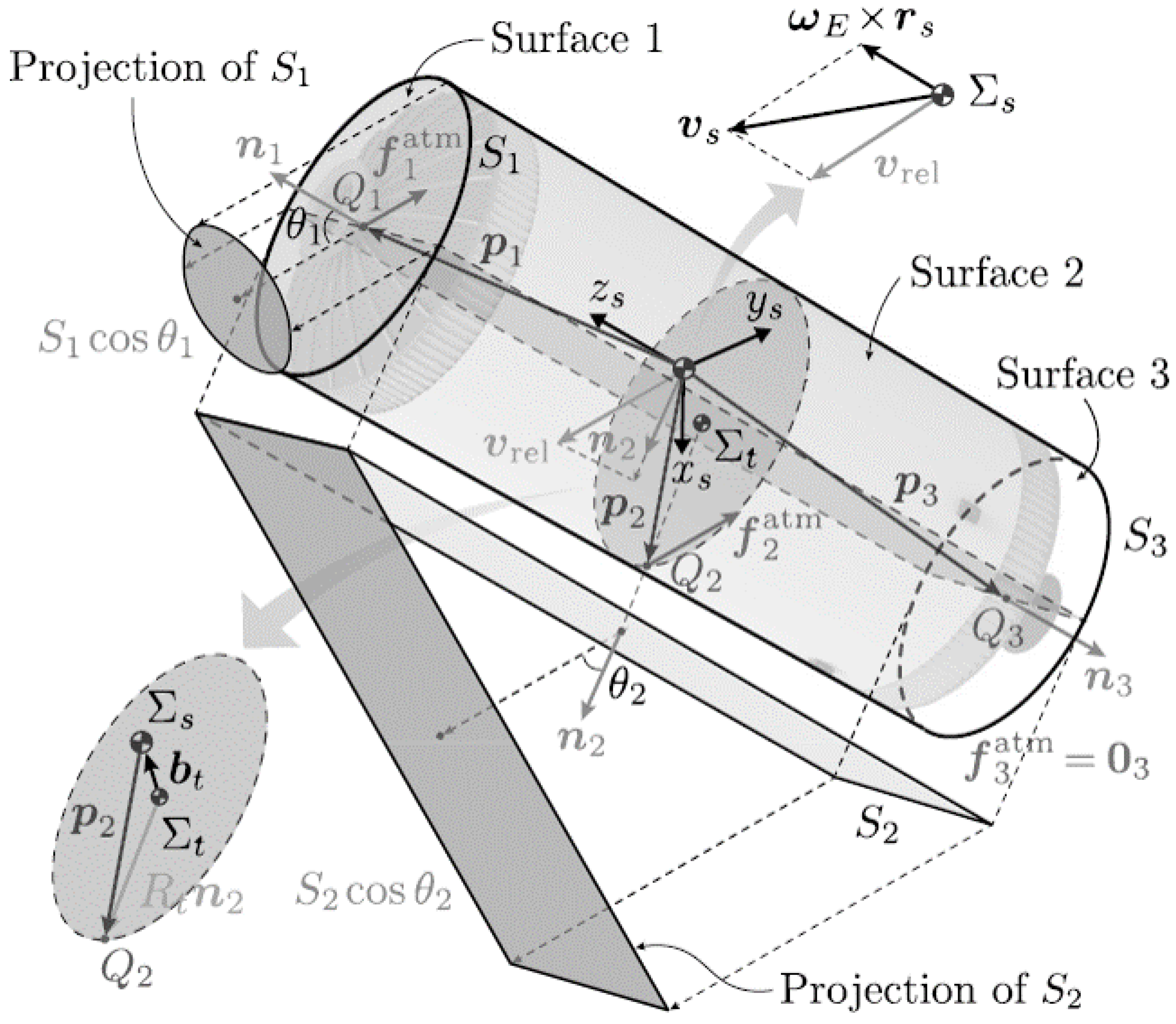
Figure 3.
An atmospheric drag schematic diagram.
Figure 3.
An atmospheric drag schematic diagram.
4.2. External Forces and Torques
The primary external forces affecting space objects in low Earth orbit (LEO) are atmospheric drag and the J2 gravitational perturbation due to Earth’s oblateness. Thus, the external force
is given by:
where
represents the gravitational force,
is the J2 perturbative force, and
is the atmospheric drag force. The gravitational force is computed as:
The J2 perturbative force is expressed as:
where is the J2 perturbation coefficient, is Earth’s equatorial radius, and is the unit vector in the inertial frame.
Atmospheric drag depends on the shape, altitude, and velocity relative to the atmosphere. If the debris is approximated as a cylinder, and the detumbling device is considered negligible in size, the atmospheric drag is calculated as:
where is the atmospheric density, is the drag coefficient, S is the cross-sectional area, and is the relative velocity between the combined system and the atmosphere.
The total external torque
acting on the system includes contributions from gravity-gradient torque and atmospheric drag torque:
where the gravity-gradient torque is:
and the atmospheric drag torque is:
with
denoting the vector from the CoM to the center of pressure of each face.
5. Controller Design
5.1. Adaptive Sliding Mode Control
Space debris typically exhibits non-cooperative behavior with uncertain inertial parameters, making it challenging to precisely control its detumbling. A robust control strategy is required to handle these parametric uncertainties and external disturbances. Sliding Mode Control (SMC) is effective for such systems with high nonlinearity and modeling uncertainties and has been widely applied in fields like robotics, aerospace, and industrial control. However, conventional SMC approaches require a large control gain based on prior knowledge of disturbance boundaries to maintain stability. If the gain is not properly tuned, this can lead to severe system chattering.
To overcome these limitations, we propose an adaptive sliding mode control scheme that improves detumbling performance while minimizing system chattering. The detumbling device is equipped with five thrusters capable of providing constant thrust
along the
,
, and
directions. We define a continuous control input vector
, where
and
. The control force and torque vectors can then be expressed as:
Given the limited thrust capacity, input saturation must be considered. To facilitate the controller design, the dynamic equation from Equation (15) is reformulated as:
where denotes the saturated control torque, and represents the lumped uncertainty caused by external disturbances and model inaccuracies.
To handle uncertainties in the control torque due to the position uncertainty of the system’s CoM, we express
as:
where the hat (^) denotes estimation, and tilde (˜) denotes uncertainty. The bounds on
can be determined using
and
:
To manage control constraints, we introduce a new control input
with
:
where
is a diagonal matrix and
is a constant vector. The adaptive sliding mode control law is given by:
where is the sliding surface, and are gain matrices, and is the adaptive term. The updating laws for the adaptive gains are defined to ensure convergence and stability based on Lyapunov stability theory.
5.2. PWPF Modulation
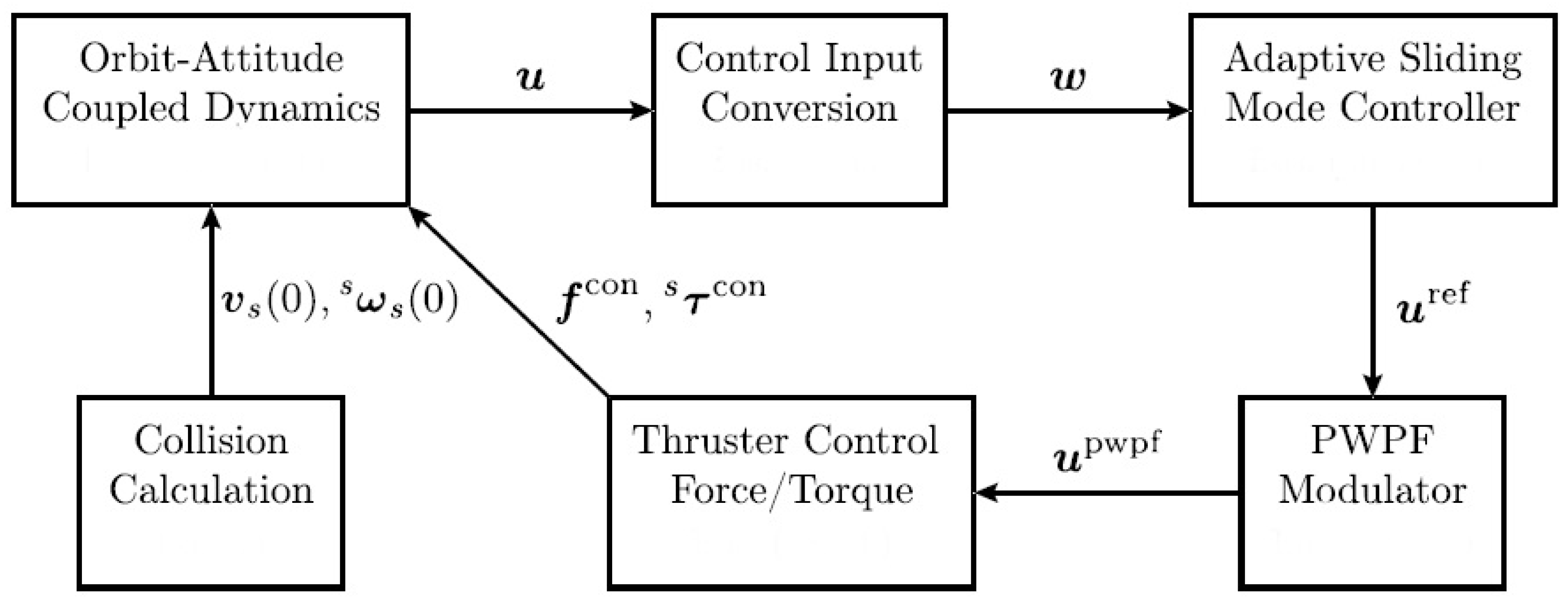
Figure 4.
A block diagram showing the suggested control plan.
Figure 4.
A block diagram showing the suggested control plan.
Figure 5.
PWPF modulator.
Figure 5.
PWPF modulator.
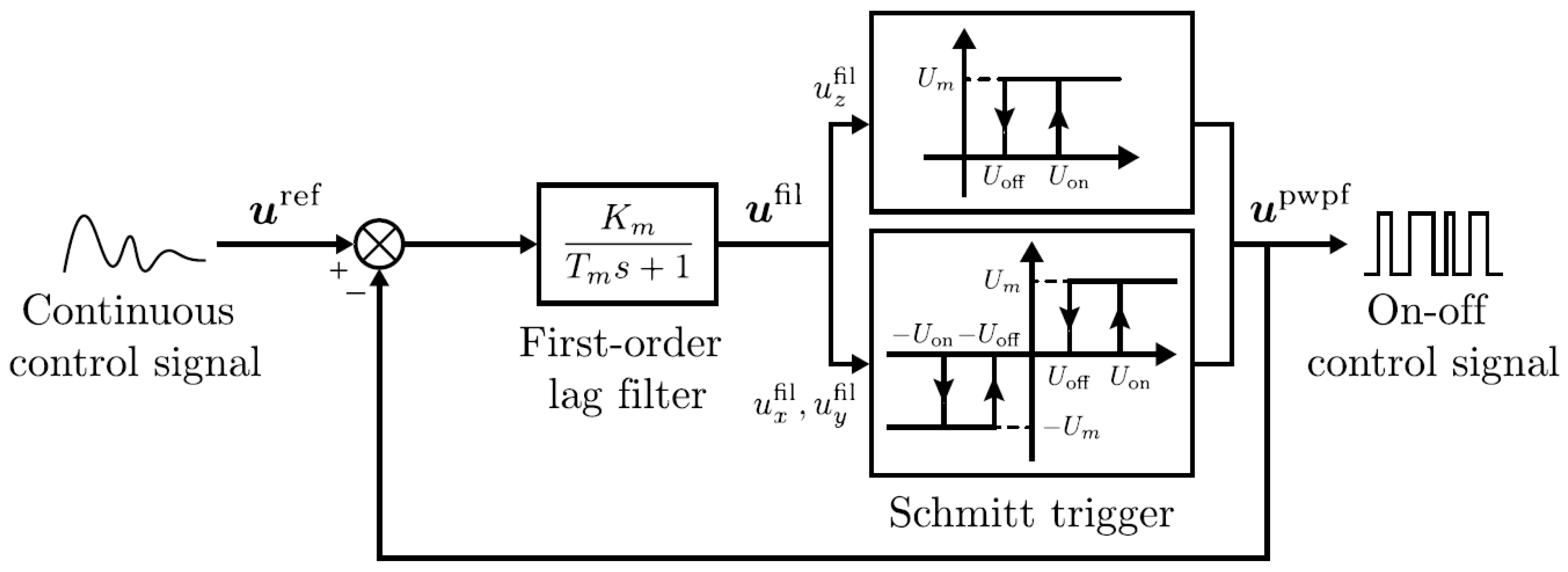
To convert the continuous control signal
into a format suitable for on-off thruster operation, Pulse Width Pulse Frequency (PWPF) modulation is employed. PWPF modulation is chosen for its near-linear operation, high efficiency, noise immunity, and tunable pulse width and frequency. The reference control signal
is derived using the pseudo-inverse of
:
The PWPF modulator, as shown in the control block diagram, includes a first-order lag filter, a Schmitt trigger, and a feedback loop. The filter output is:
where is the time constant, and is the gain. The Schmitt trigger switches the thrusters on or off based on the filtered signal, converting the continuous control forces and torques into discrete on-off commands for precise thruster control.
The proposed adaptive sliding mode controller combined with PWPF modulation provides robust, efficient control of the detumbling process for non-cooperative space debris, enhancing stability while minimizing fuel consumption and chattering.
6. Simulation Results
This section presents the numerical simulations performed to analyze the coupled orbit-attitude dynamics of the system and verify the effectiveness of the proposed adaptive sliding mode control.
Table 1 summarizes the initial conditions and inertial parameters of the target and the detumbling device.
The orbital elements of the target related to the vectors
and
are: semi-major axis of 6878.1363 km, eccentricity of 0.05, inclination of
, right ascension of ascending node
, argument of perigee
, and true anomaly
. The attitude of the detumbling device is defined by Z-Y-X Euler angles, and the associated rotation matrix is:
This results in the relative position vector m.
The relative velocity between the detumbling device and the target in the detumbling device’s frame
is given by
, and the linear velocity of the detumbling device before collision is:
Using these values, the linear and angular velocities of the combined system are computed as:
The initial inertia matrix for the combined system is:
The collision primarily caused a significant change in angular velocity, necessitating careful consideration in the control scheme. The robustness of the control strategy is tested by assuming
m and an adjusted inertia matrix:
For control, the parameters are: , , , , , , , and PWPF modulator settings are , , , , .
The simulation shows that the angular velocities of the system decrease rapidly. After 4000 seconds, they drop to approximately deg/s, and continue to decrease, indicating the control scheme’s effectiveness against uncertainties and disturbances.
The detumbling mission is completed within one orbital period, with minor changes to the orbit’s perigee and apogee. The fuel consumed for the entire detumbling process is about 0.20 kg, demonstrating that the proposed control method is efficient for handling large debris objects in space.
7. Results and Discussion
The computational aspect of the simulation was performed using numerical integration techniques to model the dynamics of the CubeSat-debris system. Specifically, the simulation was carried out using the Runge-Kutta 4th order (RK4) method with a time step of 0.1 seconds. This method was chosen for its balance between accuracy and computational efficiency, allowing for the precise tracking of the CubeSat’s attitude and motion in response to various external torques, such as gravity-gradient and magnetic disturbances. The integration accounted for both control and disturbance torques to evaluate the robustness of the proposed adaptive controller under realistic space conditions.
Figure 6.
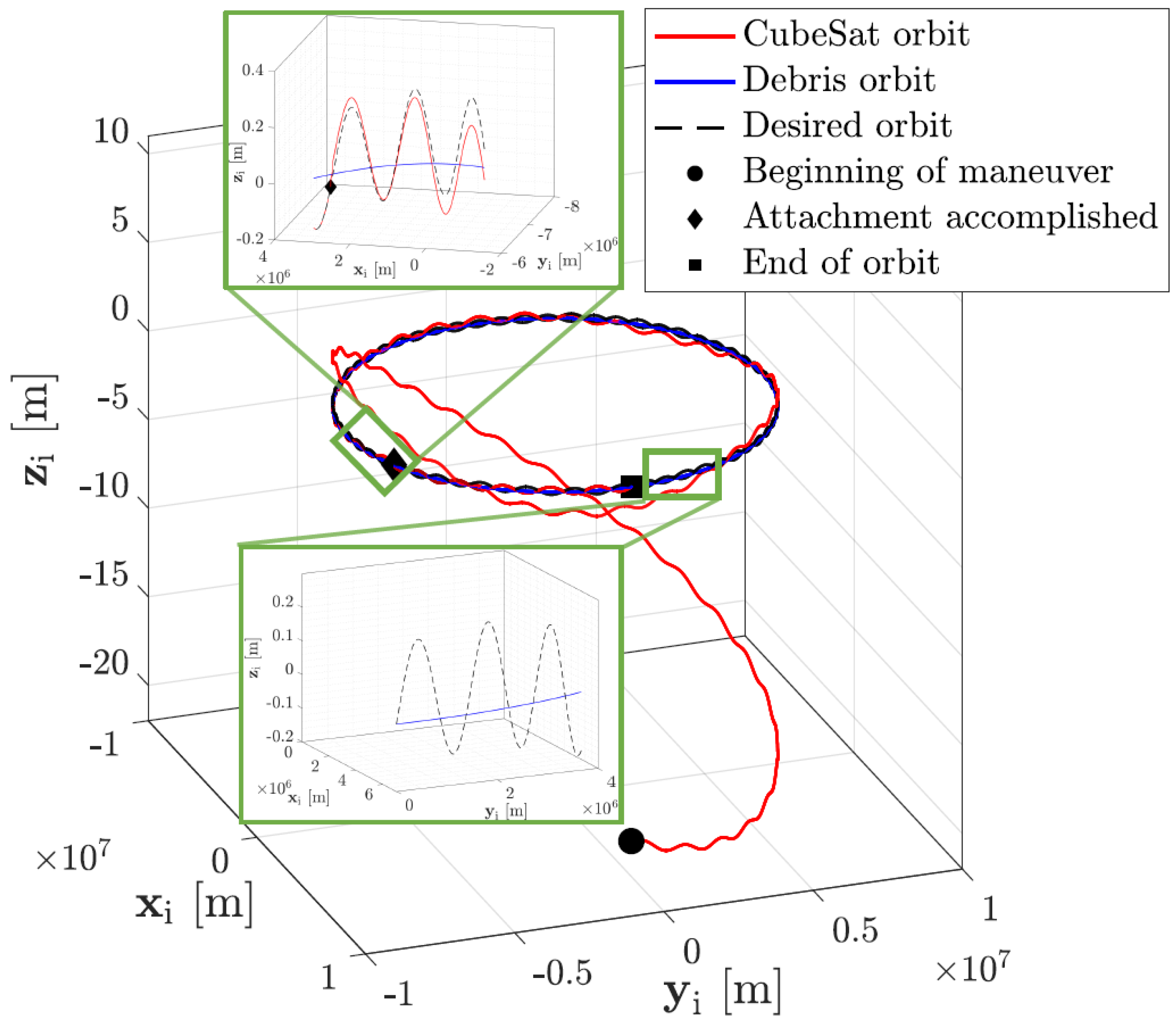
Trajectories of debris (blue), attachment point (dashed), and CubeSat (red) in inertial frame , highlighting key events during the rendezvous and attachment phases.
Figure 6.
Trajectories of debris (blue), attachment point (dashed), and CubeSat (red) in inertial frame , highlighting key events during the rendezvous and attachment phases.
Figure 7.
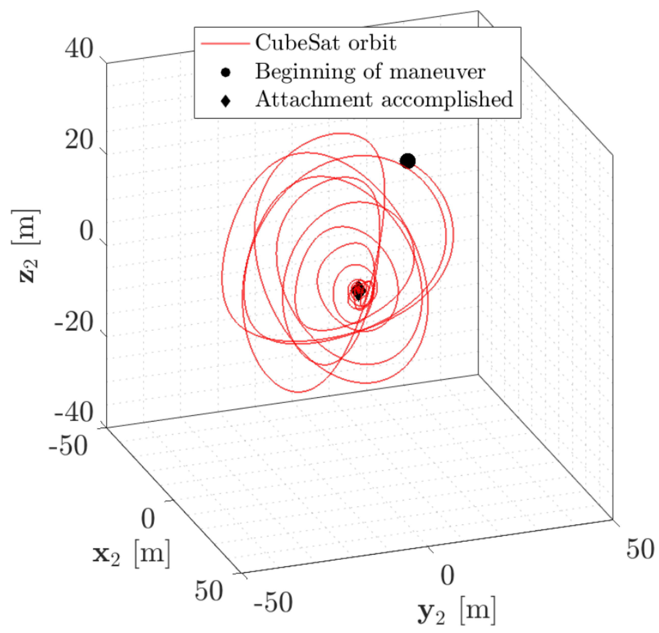
CubeSat’s trajectory relative to tumbling debris in body frame , showing its maneuver around the debris during rendezvous.
Figure 7.
CubeSat’s trajectory relative to tumbling debris in body frame , showing its maneuver around the debris during rendezvous.
The Deorbiter CubeSat starts with zero angular velocity () after stabilizing post-release. It initiates a rendezvous maneuver with tumbling debris at a starting distance of about 34.6 meters. The debris follows a nearly circular equatorial orbit, but its tumbling motion complicates the CubeSat’s path. The CubeSat completes its synchronization and rendezvous around the debris in approximately 176.7 minutes. In the debris body frame, the CubeSat’s path appears complex due to the debris’s rotation. After attachment, the CubeSat stabilizes and maintains a fixed relative position, crucial for deorbiting maneuvers.
Figure 8.
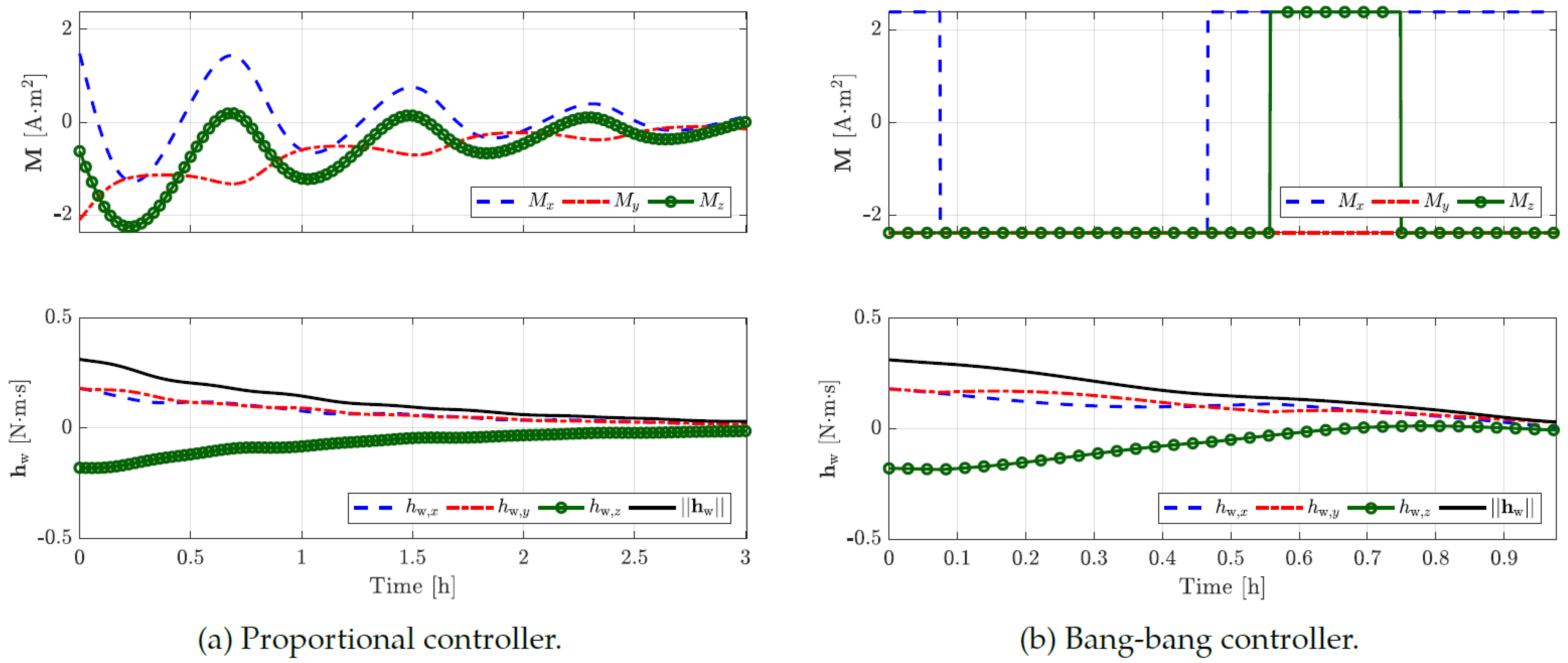
An exemplar reaction wheel momentum unloading process employing magnetorquers.
Figure 8.
An exemplar reaction wheel momentum unloading process employing magnetorquers.
The time histories of command magnetic torques and reaction wheel momentum for both proportional and bang-bang controllers reveal key differences in desaturation performance. With wheel saturation, the proportional controller takes around three hours to fully desaturate, while the bang-bang controller achieves this in just about one hour, though it draws maximum current from onboard batteries. Given an orbital period of 1.62 hours, the bang-bang controller can complete desaturation in just over half an orbit, offering a faster but more power-intensive solution.
Figure 9.
Using the time-optimal detumbling controller, the debris body rates profile during the detumbling movement.
Figure 9.
Using the time-optimal detumbling controller, the debris body rates profile during the detumbling movement.
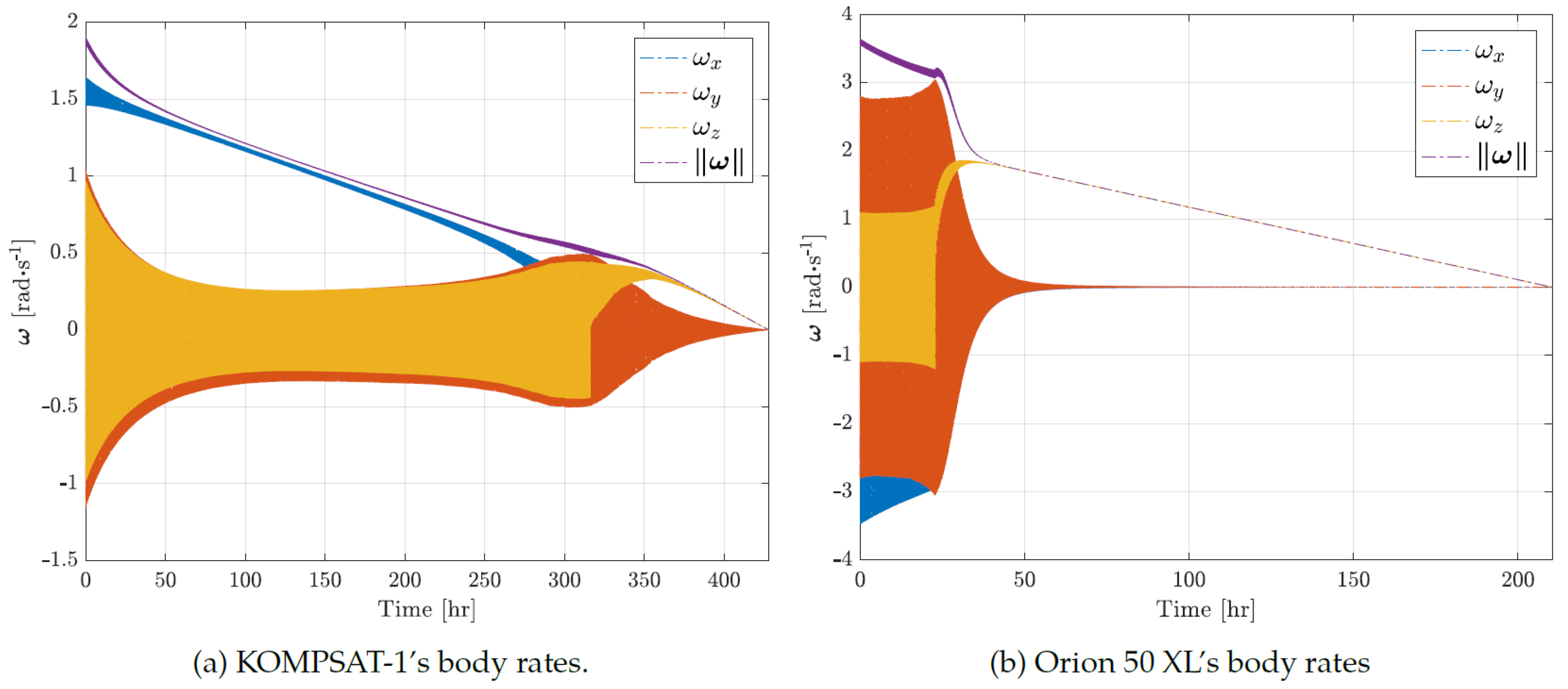
The body rate profiles of KOMPSAT-1 and Orion 50 XL show a reduction in debris body rate magnitude, , during detumbling. KOMPSAT-1 achieves detumbling in about 15 days, while Orion 50 XL takes 9 days. However, the full detumbling maneuver includes momentum unloading from reaction wheels, which takes about 25 days for KOMPSAT-1 (3,298 events) and 38 days for Orion 50 XL (1,116 events). The lengthy unloading time is due to the debris’ high moment of inertia relative to the reaction wheels, causing frequent wheel saturation and requiring numerous unloading cycles.
Figure 10.
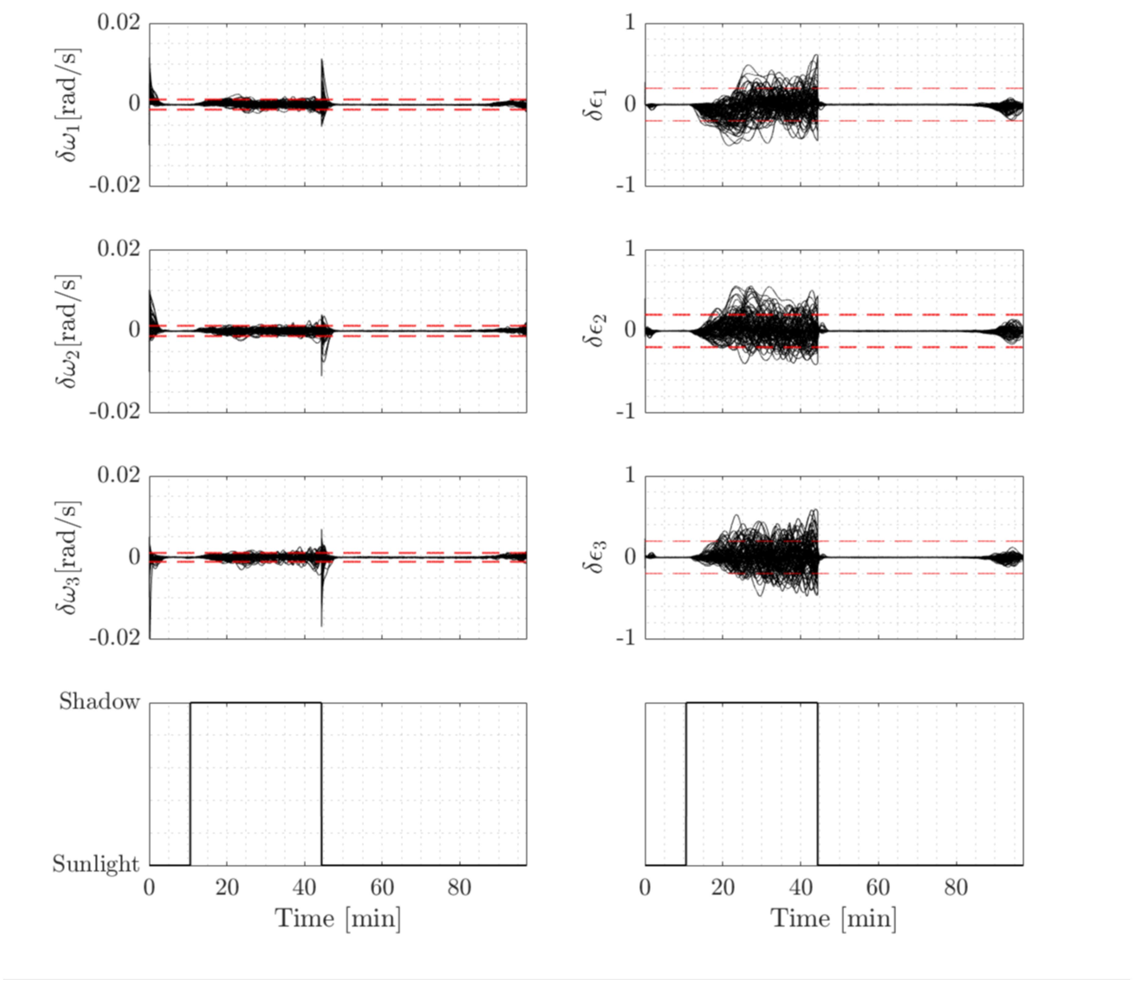
Results of a Monte Carlo simulation for mean 3 bounds (red dashed lines) and errors in angular velocities and quaternion parameters (black solid lines) during a single circle.
Figure 10.
Results of a Monte Carlo simulation for mean 3 bounds (red dashed lines) and errors in angular velocities and quaternion parameters (black solid lines) during a single circle.
When the spacecraft is in sunlight, sun sensor measurements enable the estimator to quickly align the predicted and estimated states, minimizing transient errors caused by aggressive initial conditions. However, during an eclipse, the estimator must rely on magnetometer and rate sensor data, which are less accurate than sun sensors. As a result, the accuracy of the estimated quaternion deteriorates.
To evaluate the robustness of the attitude estimator against various initial conditions, a Monte Carlo simulation with 200 runs was performed using a norm-constrained Extended Kalman Filter (EKF) for a nominal orbit. Plotting the angular velocity and quaternion errors from these runs. The quaternion errors, , are computed using a multiplicative quaternion error formulation to maintain the unit length constraint.
The study focuses on two debris objects: the defunct KOMPSAT-1 satellite and the Orion 50 XL motor. As of June 1, 2017, KOMPSAT-1 was in a near-circular, highly inclined orbit with an average altitude of 650 km, while Orion 50 XL had a lower inclination but a more eccentric orbit, with a perigee altitude of about 420 km and an apogee altitude of 1400 km. Both orbits are within the operational region for the Deorbiter CubeSat mission.
Figure 11.
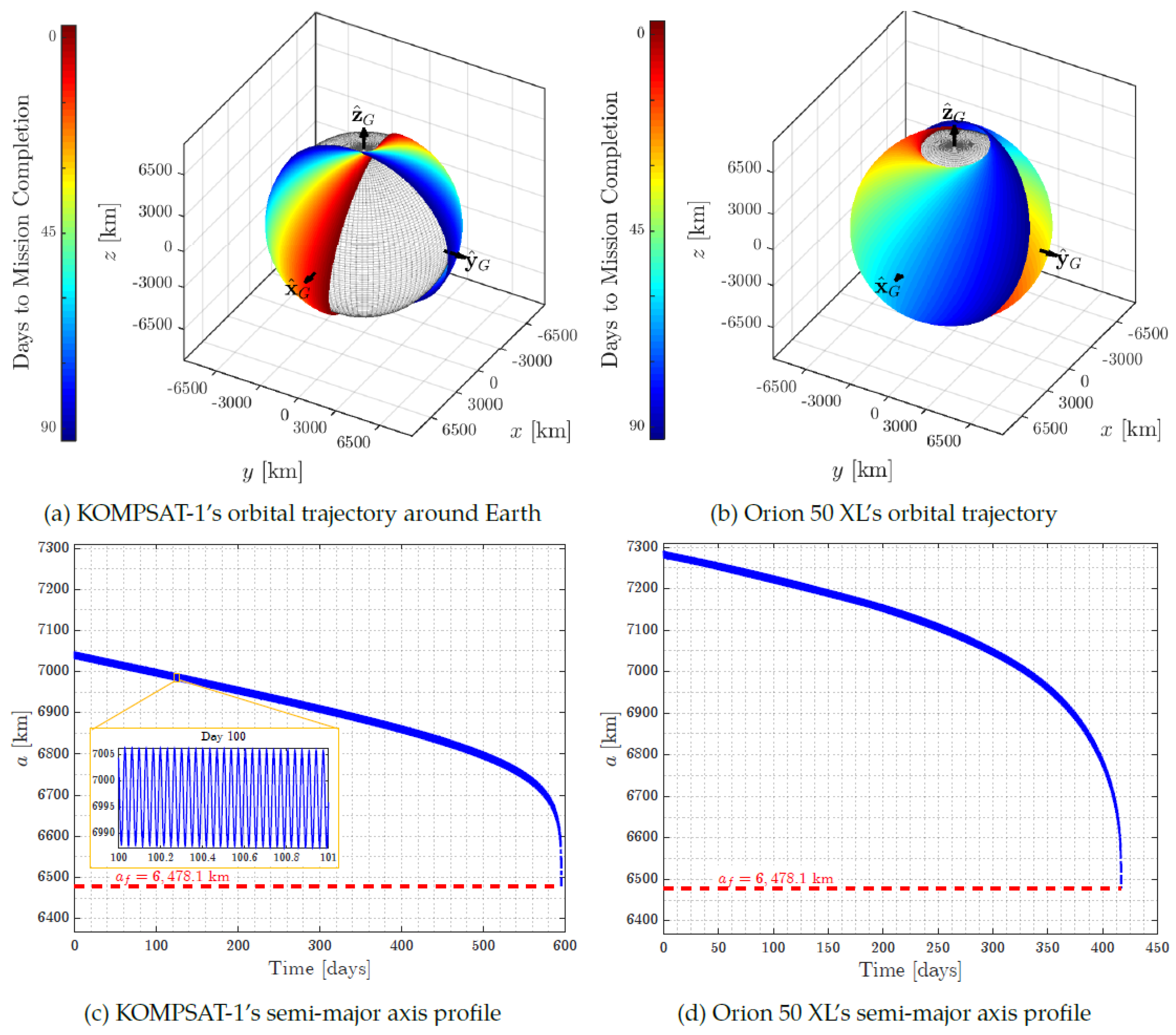
The system’s low-thrust spiral orbital trajectory over the previous ninety days, along with the semi-major axes of debris being reduced to = 6478:1 km.
Figure 11.
The system’s low-thrust spiral orbital trajectory over the previous ninety days, along with the semi-major axes of debris being reduced to = 6478:1 km.
During deorbiting maneuvers, the CubeSat propulsion system, aided by atmospheric drag, reduced KOMPSAT-1’s semi-major axis from 7,045 km to 6,478.1 km over 596 days (1.6 years). For Orion 50 XL, the semi-major axis decreased from 7,290 km to 6,478.1 km within 417 days. Without intervention, natural orbital decay for objects above 500 km altitude typically takes decades. Specifically, under optimal conditions, KOMPSAT-1 would remain in orbit for approximately 95 years and Orion 50 XL for about 22 years, assuming they maintain maximum cross-sectional areas perpendicular to their velocity.
The Deorbiter CubeSat significantly shortens the decay times of both debris objects. The simulation accounts for the J2 perturbation effect, which causes nodal regression as the debris undergoes deorbiting. While J2 causes secular changes in the right ascension of the ascending node (RAAN) and argument of perigee, it only produces periodic variations in the semi-major axis, inclination, and eccentricity. The nodal regression is more pronounced for Orion 50 XL due to its smaller orbital inclination compared to KOMPSAT-1.
8. Conclusions
This paper investigates the dynamics and control mechanisms of a novel adhesion detumbling strategy, specifically using a harpoon-nanosatellite system to stabilize space debris. A used rocket upper stage is selected as the target for this study. Initially, the collision dynamics between the detumbling device and the debris are modeled. Given the extremely brief duration of the collision, external disturbances are neglected. Consequently, the post-collision motion state of the combined system is determined by the principles of conservation of linear and angular momentum.
To precisely simulate the motion of the debris and nanosatellite system during the detumbling process, an orbit-attitude coupled dynamics model is constructed. This model incorporates time-varying external disturbances and variable inertial parameters. Since debris objects are typically non-cooperative and their inertial properties are challenging to determine accurately, an adaptive sliding mode control (SMC) scheme is developed. This control approach is robust to parameter uncertainties and incorporates input saturation to manage control efforts effectively. To convert the continuous control signal into a form suitable for thruster implementation, a Pulse Width Pulse Frequency (PWPF) modulator is employed.
Key findings from the simulations are summarized as follows:
The collision significantly reduces the angular velocity of the debris from an initial state of deg/s to deg/s. This substantial change in angular velocity must be considered when planning detumbling operations.
The proposed adaptive sliding mode control (SMC) scheme demonstrates high efficiency, low fuel consumption, and strong robustness. Under this control scheme, the angular velocity of the non-cooperative debris decreases rapidly within 4000 seconds (approximately one orbital period) and reaches near-zero within 8000 seconds.
The total impulse generated by the thrusters increases sharply to 429.54 Ns at 3760 seconds and gradually rises to 438.35 Ns by 8000 seconds. The fuel consumed in the entire detumbling process is minimal, approximately 0.20 kg.
The detumbling maneuvers do not significantly alter the target’s orbit, thereby minimizing the risk of potential collisions with other operational spacecraft in different orbits.
These results underscore the effectiveness of the harpoon-nanosatellite-based adhesion detumbling strategy for stabilizing non-cooperative space debris, providing a viable approach for future active debris removal missions.
9. Acknowledgements
I would like to extend their sincere gratitude to ClearSpace and the European Space Agency (ESA) for their invaluable assistance in verifying the simulations and providing essential computational resources. Their guidance and support have been pivotal in ensuring the accuracy and robustness of our results.
I also wish to thank the Indian Space Research Organisation (ISRO) for facilitating connections with these esteemed institutions, fostering an environment conducive to collaboration and knowledge exchange.
Furthermore, I gratefully acknowledge the support from the German Aerospace Center (DLR) and the Jugend Forscht program for providing grants that enabled me to pursue this research. Their funding and encouragement have been crucial in allowing us to explore innovative approaches to space debris removal.
Finally, I appreciate all the feedback and insights provided by various experts and collaborators during the research and manuscript preparation phase.
References
- Li, H., Zhang, G., Liu, H., Liu, J., & Tang, G. (2019). Adaptive Sliding Mode Control for Space Debris Removal Using a Flexible Grasping Manipulator. Acta Astronautica, 163, 1-16.
- Xu, Y., Li, H., Xie, L., & Tang, G. (2020). A Review of Active Space Debris Removal Methods. Progress in Aerospace Sciences, 118, 100640.
- Song, H., Wang, J., Lu, L., & Li, Y. (2018). Model Predictive Control of Space Manipulator for Space Debris Removal in the Presence of Uncertainty. Journal of Guidance, Control, and Dynamics, 41(3), 681-694.
- Yang, W., Shi, P., Liu, D., & Ren, L. (2021). Design and Validation of a Hybrid Active Debris Removal System for Large Space Debris. Acta Astronautica, 179, 246-257.
- Menon, C., Ross, I., & Kuga, H. K. (2019). Kinematic and Dynamic Modeling of a Harpoon-Based Space Debris Removal System. Aerospace Science and Technology, 86, 822-834.
- Araki, Y., & Aoyama, H. (2020). Coupled Orbit-Attitude Dynamics of Space Debris during Detumbling by a Deorbit Device. Journal of Guidance, Control, and Dynamics, 43(6), 1085-1097.
- Liu, Y., Liu, M., Li, Z., Tang, G., & Zhao, J. (2019). Adaptive Robust Control for Space Debris Capturing with Uncertain Dynamics. IEEE Transactions on Aerospace and Electronic Systems, 55(3), 1444-1457.
- Wang, Z., Li, X., Liu, J., & Zhu, Y. (2021). High-Fidelity Coupled Dynamics Modeling and Sliding Mode Control of Space Debris with Flexible Appendages. Aerospace Science and Technology, 113, 106689.
- Xu, Y., Zhang, H., Sun, J., & Tang, G. (2022). Optimization-Based Approach for Autonomous Space Debris Removal Missions. Acta Astronautica, 198, 405-416.
- Zhang, Q., Meng, D., Jiang, B., & Su, H. (2017). Sliding Mode Control for Space Robotic Systems in the Presence of Environmental Disturbances. International Journal of Control, Automation, and Systems, 15(2), 684-692.
- He, Y., Jiang, Z., Wang, Q., & Qiao, Z. (2019). Adaptive Sliding Mode Control for Attitude Stabilization of Tumbling Space Debris. IEEE Access, 7, 121325-121337.
- Li, Z., Sun, J., Wang, M., & Wu, H. (2021). A Review on Autonomous Rendezvous and Docking of Spacecraft. IEEE Access, 9, 167816-167838.
- Dong, Y., Wu, X., Zhang, Y., & Qiu, L. (2022). Adaptive Control of a Space Debris Removal System Using a Harpoon-Based Mechanism. Acta Astronautica, 190, 506-518.
- Zhang, X., Liu, H., Shi, P., & Tang, G. (2019). Adaptive Sliding Mode Control of Spacecraft for Active Debris Removal in a Perturbed Environment. Aerospace Science and Technology, 84, 205-216.
- Watanabe, T., Fujimoto, H., & Uchiyama, N. (2023). Analysis and Control of Attitude Dynamics for Debris Removal Using a Harpoon-Based System. Advances in Space Research, 72(2), 405-418.
Table 1.
Initial Conditions and Inertial Parameters.
Table 1.
Initial Conditions and Inertial Parameters.
| Symbol |
Value |
Unit |
| Target |
|
400 |
kg |
|
diag(520, 520, 180) |
|
|
3.0, 0.6 |
m |
|
|
m |
|
|
km |
|
|
- |
|
|
km/s |
|
|
deg/s |
| Detumbling Device |
|
10 |
kg |
|
diag(0.32, 0.32, 0.04) |
|
|
|
m |
|
|
deg |
|
|
m/s |
|
|
deg/s |
|
0.1 |
N |
|
220 |
N·s |
|
Disclaimer/Publisher’s Note: The statements, opinions and data contained in all publications are solely those of the individual author(s) and contributor(s) and not of MDPI and/or the editor(s). MDPI and/or the editor(s) disclaim responsibility for any injury to people or property resulting from any ideas, methods, instructions or products referred to in the content. |
© 2024 by the authors. Licensee MDPI, Basel, Switzerland. This article is an open access article distributed under the terms and conditions of the Creative Commons Attribution (CC BY) license (http://creativecommons.org/licenses/by/4.0/).
