1. Introduction
The modern era of electronic products influences electrical drives a lot. These drives have many advantages, as the electrical energy is easy to transport and can be environmentally friendly. Last developments enable the electrical drives to convert energy with high efficiency and have flexible control characteristics. Actual design solutions have various options to combine parameters as speed, torque, and power operation [1]. The electrical drives use electric motors as the prime movers, and the motors has experienced accelerated development recently. These electromechanical devices are used to convert electrical power into mechanical power and have a large variety of types. The study is focused over one type – the stepper motor. This is a brushless motor that can divide a full rotation into an equal number of steps and can be accurately controlled with no feedback mechanism. Their mechanical characteristic (full torque at standstill), pulse control (proportional to the rotation angle), respective speed control, precise positioning, and repeatability of movement, are of importance for certain applications. Stepper motors are used for applications in actuators (digital, as they do not require digital‒to‒analog conversion) and other devices (3D printers, medical instruments, satellite, navigation, disk drives, and robotics) that require reliable conversion of electrical pulses into discrete mechanical movements [
2,
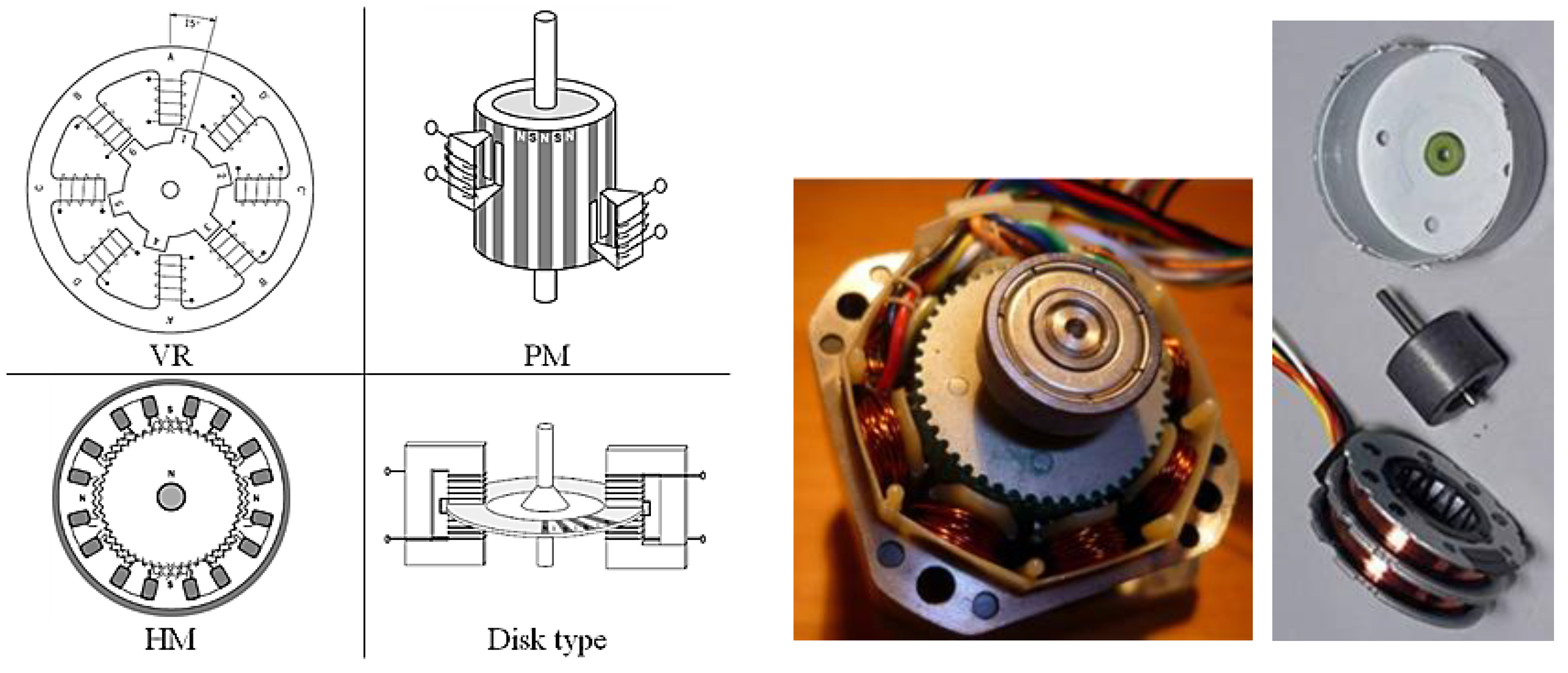
3]. The design of stepper motors differ significantly from AC and DC motors. The stator is made with differentiated poles and contains 1-24 phases that connect to the motor control system to create a rotating magnetic field. The rotor is also made with differentiated poles, but no electrical energy is supplied to it, and it can be one of the following three basic types: VR (Variable-Reluctance) - made of soft magnetic material with the required number of poles; PM (Permanent Magnet) – made of a permanent magnet with the required number of poles; HM (Hybrid) – a combination of the above two types. There are also some specific designs of stepped EDs, such as the disc ones. Principal schemes of these types of design, together with samples of stepper motors, are shown in
Figure 1.
These electrical motors have been subjected in various studies recent years, but mainly directed to their control [
4,
5,
6,
7]. Some other studies are oriented to model the electromagnetic behavior of the motor as to obtain more clear view over design parameters and their influence on the performance characteristic, using empirical approach and formula [
5,
8,
9]. Furthermore, design studies are designated to explore in detail the stepper motor design via virtual prototyping techniques as Finite Element Analysis (FEA) [
10,
11,
12]. Virtual prototyping is established as a conventional tool, used widely in product design process (PDP), and subjected in many studies [
13,
14,
15]. It allows also performing optimization in very shortened terms and generally accelerates the entire PDP [
16,
17]. The advantages of working with virtual prototype are many, but for certain problems the combination with physical testing [
18] gives further tools to obtain a better design.
This study is focused on a newly proposed methodology for development of a stepper motor design, based on virtual prototyping, but using physical testing of a prototype in the final phase to precise the details. The aim is to use the advantages of virtual prototyping for easy change of complex design geometry, obtaining generalized results. This is used for a start point for detailed design study using physical prototypes and testing.
2. Method
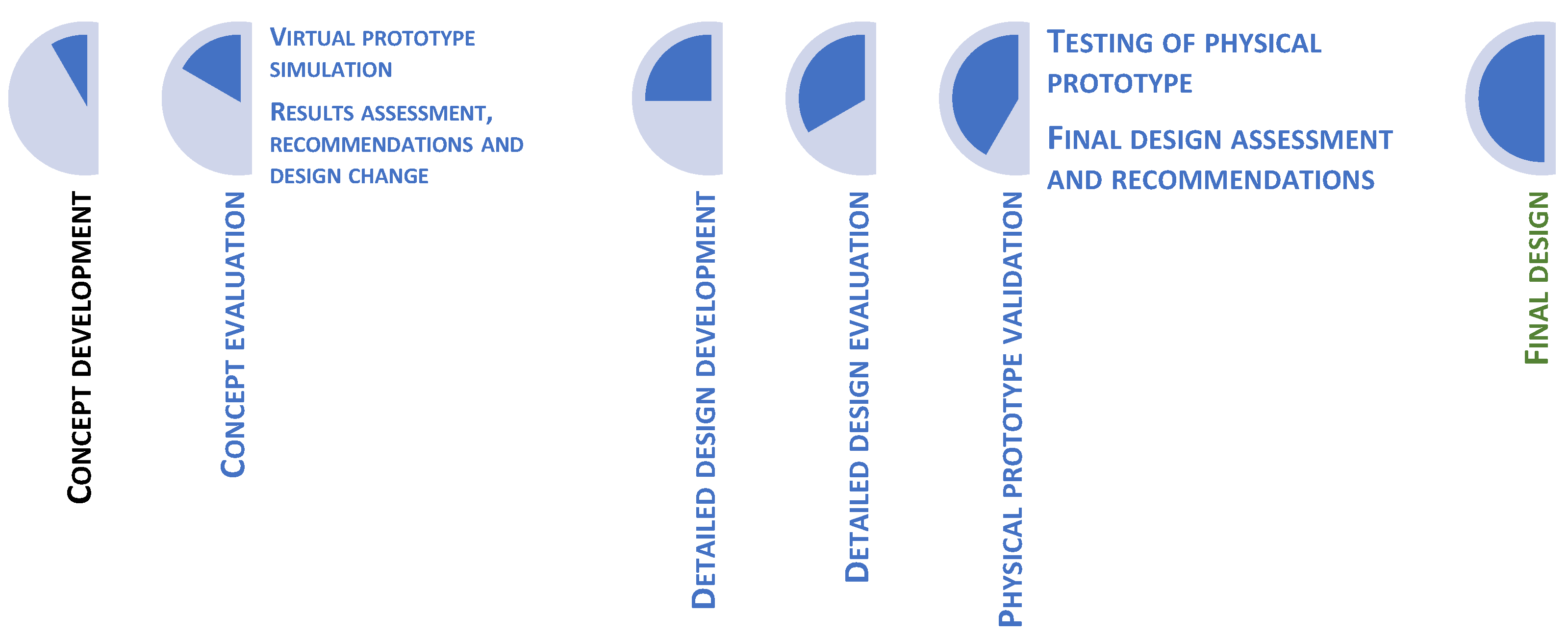
Developed methodology uses next steps in the design development of a permanent magnet (PM) stepper motor:
S1: Concept development – this step is very important and it is related to the choice of general design specifics. It starts with existing solutions (patents, research studies), selection of basic parameters and concept. System concept development and its place in the PDP is subjected in various research studies [
19,
20,
21].
-
S2: Concept evaluation – developed concept is used to build a virtual prototype that is to be subjected on various tests by finite element method simulations. The results are carefully examined, generalized and certain recommendations for detailed design are elaborated.
- ○
S2.1: Virtual prototype simulation – initially, the geometry model is to be prepared and a mesh is to be build. Many models are highly dependent on the correct material input data and certain attention is to be paid. Next is the simulation setting up, where various simulation parameters are to be defined. It requires proper knowledge over specifics of used technology [
22,
23,
24,
25].
- ○
S2.2: Results assessment, recommendations and design change – another important step, because it could facilitate understanding of physical process being modelled. It also helps to extract certain conclusions and predefines further steps.
S3: Detailed design development – next step is to develop the design in further details, implementing all recommendations and marks for its change. It is performed over the virtual prototype, using tools for CAD. Performed changes in geometry allows to obtain a more detailed geometry, but suitable for mesh generation and simulation model creation.
S4: Detailed design evaluation – similarly to S2, a virtual prototype is examined as to determine main design characteristics and to obtain recommendations for further improvement, if any.
-
S5: Physical prototype validation – finally, the performed simulations over the virtual prototype are to be validated using testing of a physical prototype. This is also a common practice, used in various engineering areas [
18,
26,
27].
- ○
S5.1: Testing of physical prototype – a prototype, with some design variants included, is to be produced, and used further for tests. The main target is to measure mechanical parameters as torque.
- ○
S5.2: Final design assessment and recommendations – this final step aims to summarize all information from virtual and physical tests and to elaborate recommendations for the final design of developed stepper motor.
S6: Final design – updated information on the stepper motor design by means of any technical documentation as drawings, technical parameters, etc.
Figure 2.
Methodology for stepper motor design development.
Figure 2.
Methodology for stepper motor design development.
Above described methodology is illustrated by an industrial case of stepper motor design development in the further chapters
3. Results and Discussion
3.1. Specification of Developed Stepper Motor
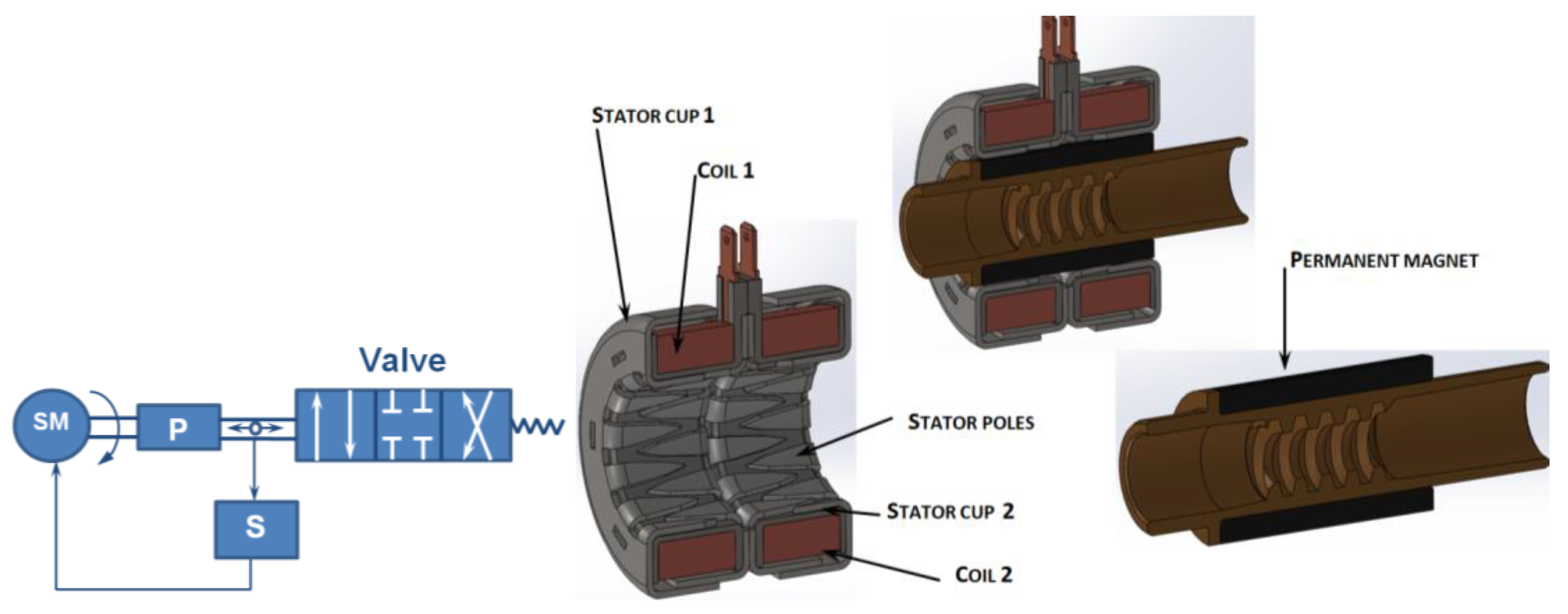
The stepper motor that is to be developed is planned to be used in a hydraulic valve drive. The target is to perform linear motion that will position the piston of the valve, depending on the command. A scheme is shown in
Figure 3.
Major design parameters to be achieved are as follows:
Stepper motor type: permanent magnet
Stroke: ±12mm
Axial force: min 100N
Overall diameter: max 32mm
Positioning axial step: max 0.03mm
3.2. S1: Concept Development
The electric stepper motor concept is shown in
Figure 3. The design consists of a stator having two identical subassemblies. The two coils are assembled into stator cups, each of which has 24 distinct poles shaped like teeth. The offset between the two sub-assemblies makes it possible to realize a division of 1/48 or 48 steps in a revolution, which allows the positioning to be sufficiently accurate and to satisfy the requirement for positioning axial step. The rotor consists of a driving shaft with internal thread on which a permanent magnet is assembled, having a total of 24 poles arranged tangentially to the magnet. This construction is conventional and based on the required parameters (torque) in a specific possible volume. The main limitation is the diametrical size, which should not exceed 32mm.
The increased torque at the Ø32 electric motor size is achieved through increased axial size. The rotary motion of the electric motor rotor is transformed into a reciprocating motion by means of a Tr8x1 trapezoidal thread. The thread is self-retaining, which ensures the stable position of the working body. Regardless of the possible high manufacturing accuracy, there is an axial play in the thread. This is intended to be compensated by the feedback monitoring the position of the final working body (plunger). The screw is locked against yaw at its rear end, where it moves on its axis.
Feedback is provided by monitoring the screw position using a Hall sensor. The axial movement of the screw leads to the displacement of the permanent magnet glued to it, whose magnetic field is read by a magnetic sensor (Hall sensor). The sensor is a conventional component and allows it to be used to control drives of this type.
3.3. S2: Concept Evaluation
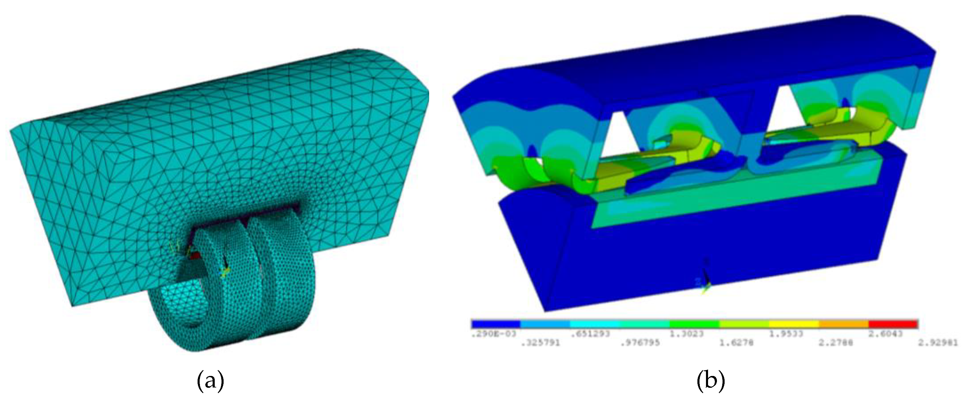
The simulation model is built based on the prepared CAD model used to develop the proposed concept. It includes only components directly relevant to the studied electromagnetic problem: a stator consisting of 4 pcs. stator cups, 2 pcs. coils, and a rotor consisting of 12 pcs. magnets (NdFeB, VMM5SHМ) and a core of mild steel. All small geometric objects (chamfers, small rounds) have been removed for simplicity. The coils are modeled as a solid-state ring. Due to the cyclic geometry of the investigated stepper motor, only one segment of the general model was used, closing within 60º. The air medium is also represented as a segment of a cylinder, the dimensions of which are chosen so as not to affect the electromagnetic flux. The final form of the geometric model used for the computational model is shown in figure 4, together with a sample for obtained results. The model is simulated at nominal voltage of 12V and corresponding to the resistance current of 360mA. Calculated mechanical torque is of 80.3mNm. This value corresponds to an axial force of about 147N in the screw, which corresponds to the specification.
Figure 4.
Simulation model for concept evaluation and results: (a) Mesh model; (b) Distribution of magnetic field induction, T.
Figure 4.
Simulation model for concept evaluation and results: (a) Mesh model; (b) Distribution of magnetic field induction, T.
This concept assessment shows that there is a sufficient potential in it and it should be developed further. Several recommendations are concluded:
Magnetic field could be improved, especially by precision in the teeth of the stator cups (poles);
Strong magnets from NdFeB require slots that are not friendly to mass production. Replacement of these magnets with sintered bushing is expected to decrease significantly output mechanical torque;
Design parameters could be examined further by virtual prototyping of the developed in detail design.
3.3. S3: Detailed Design Development
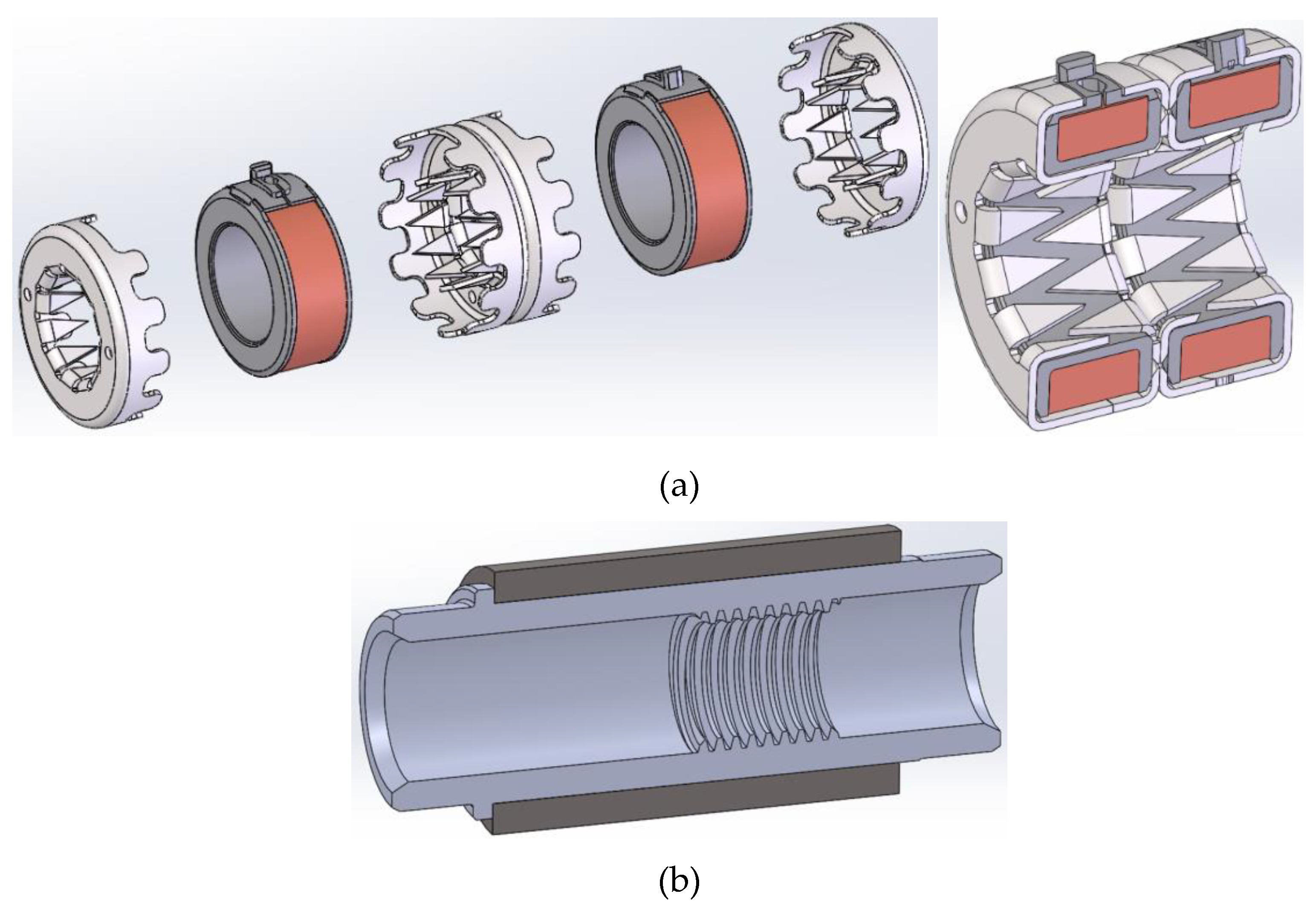
A detailed design is developed, using results from performed simulations over the virtual prototype of the concept. It is shown by its major components in
Figure 5. A ring component is added as it is needed to hold the coil. Stator cups are designed in greater detail, aligning their geometry to available technology tools and machines.
3.4. S4: Detailed Design Evaluation
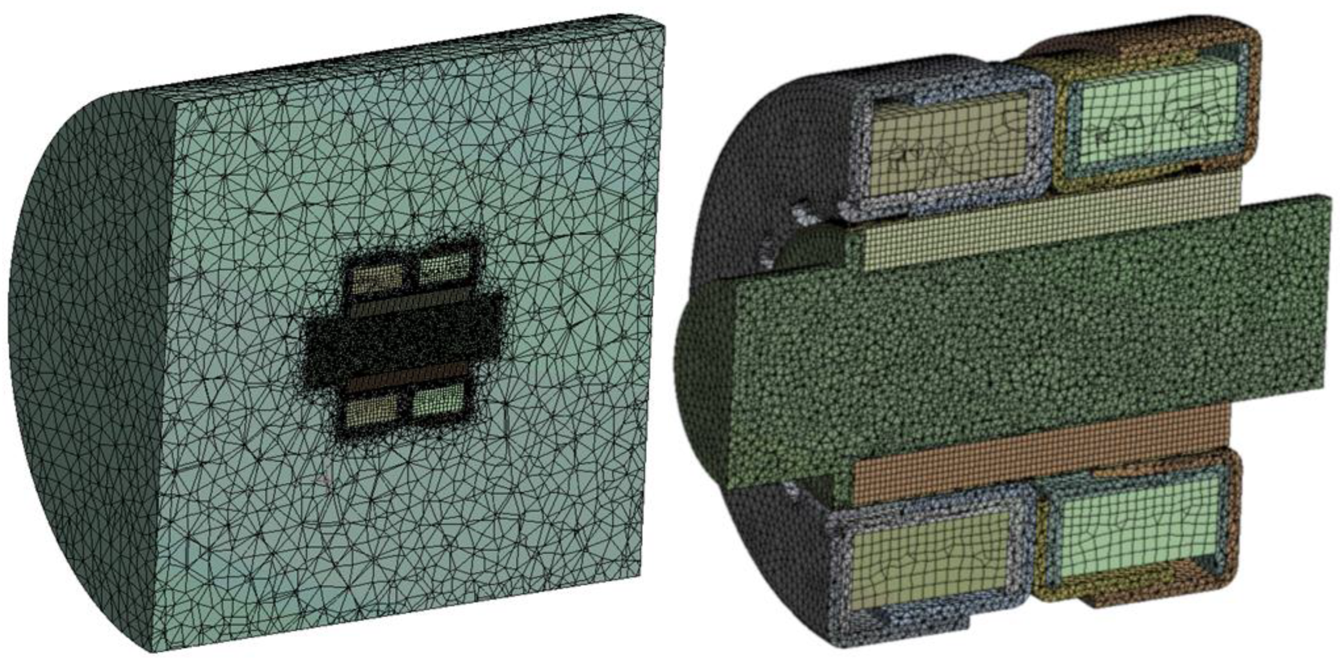
Another set of simulations is performed, using next stage of design development, where most of the components are developed in higher detail. Entire model is prepared for simulation, again including the surrounding air media. The mesh model is presented in
Figure 6.
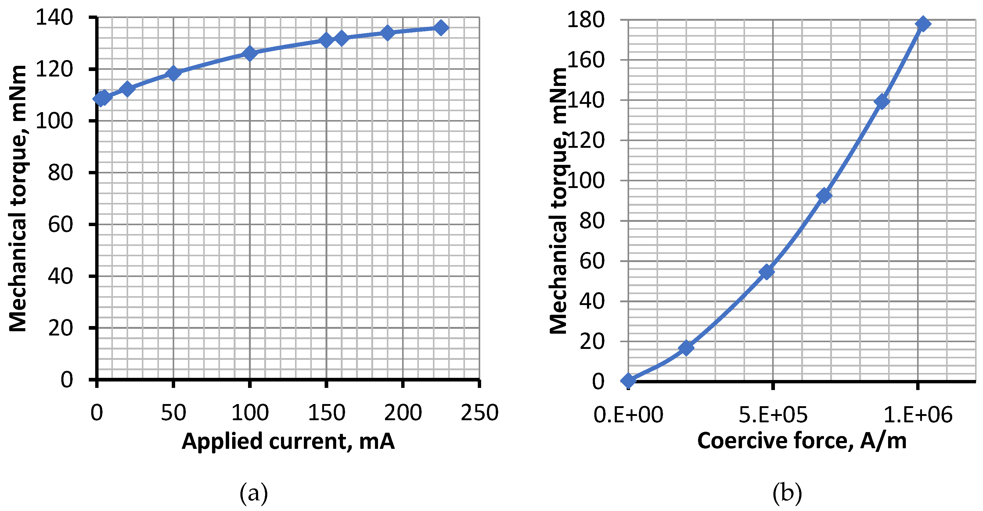
The study aims to examine the stepper motor also concerning its performance at different values of applied current, and combinations of its directions in coils. This will help further adjustment of motor control. Second parameter that is explored is the coercive force of the permanent magnet. Obtained results are shown graphically in
Figure 7.
It is evident that the current in the coils has small, near to linear effect over the mechanical torque. In opposite, the magnet strength has high influence over stepper motor output. Further various experiments using built virtual prototype are performed, resulting in a complex data that is analyzed. Final choice of design parameters are further restricted by so called manufacturing constraints, and moreover – by the financial parameters of design.
This is a strong example of the opportunities that virtual prototyping gives in means of vast evaluation of complex set of parameters.
3.5. S5: Physical Prototype Validation
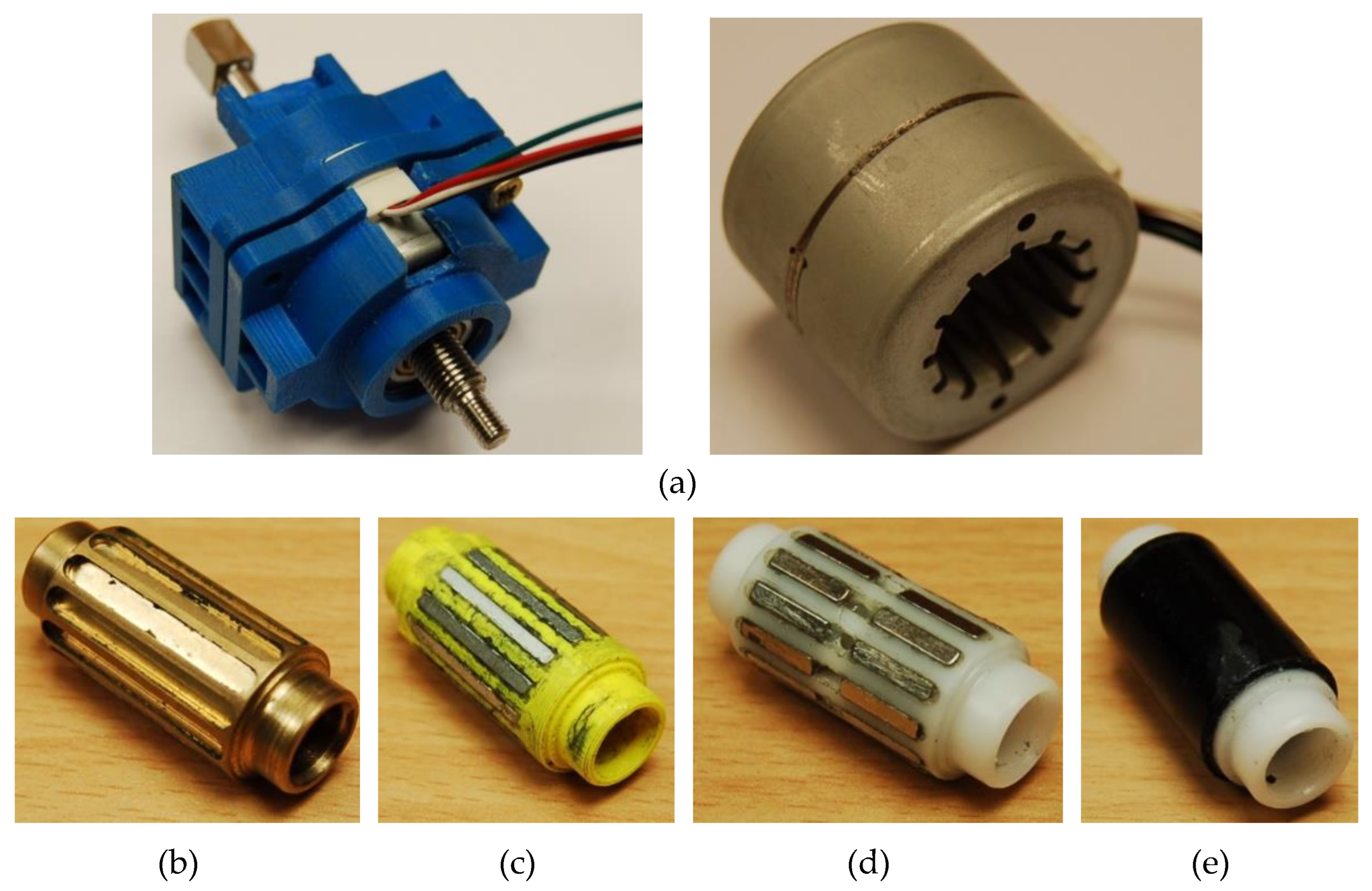
The physical prototype of the final design is shown in
Figure 8. The tested stepper motor is placed in a specially produced housing, using rapid prototyping technology. The stator is prepared using mass production technology and has some modifications, based mainly on recommendations from simulations results from the previous step S4.
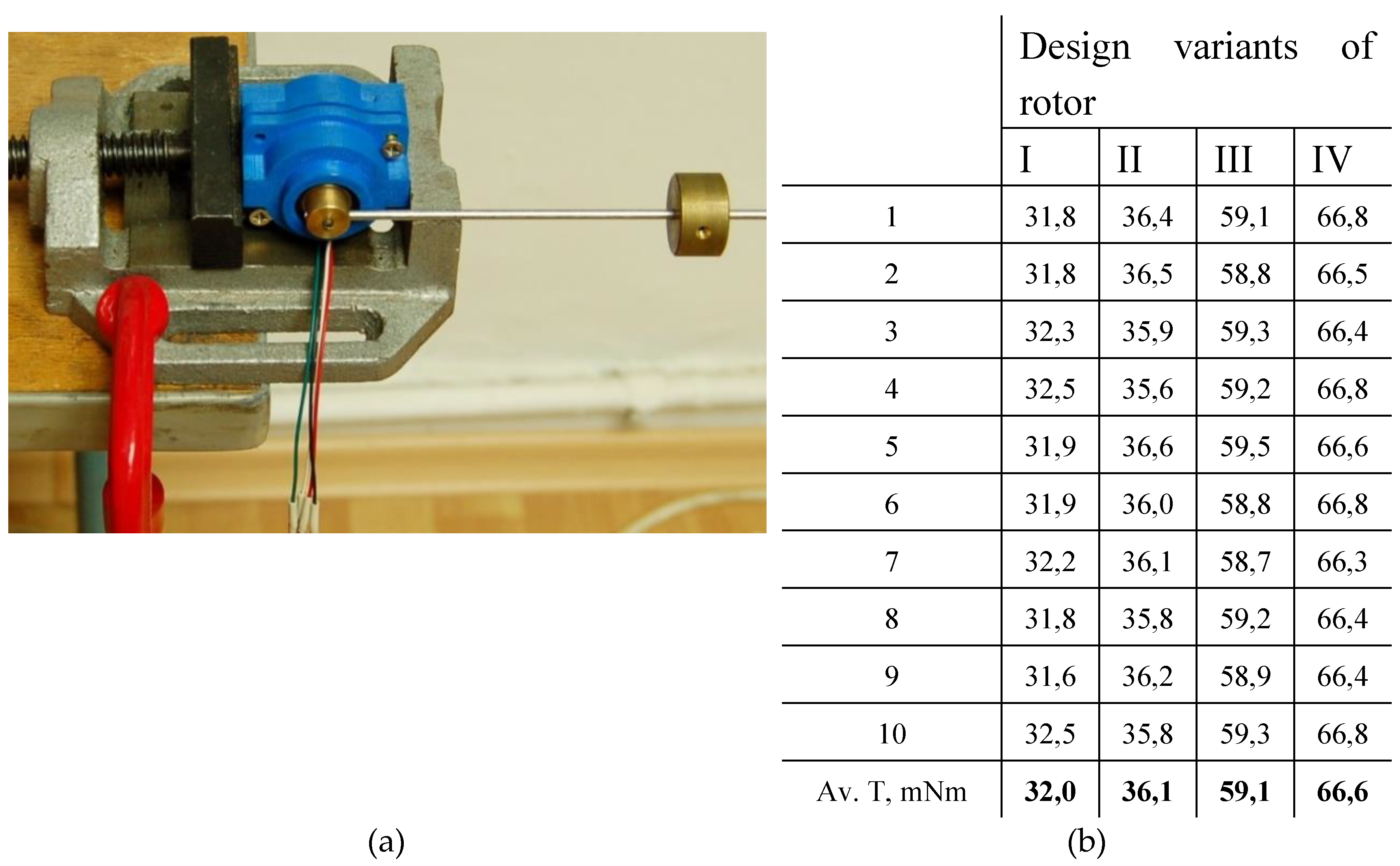
Four variants of rotor permanent magnet are tested, shown in
Figure 8 too. The target is to choose between stronger, but slotted and expensive variants, and sintered one (Variant IV). Performed tests are at voltage of 12V and applied current of 400 mA. Measured parameter is for holding torque, and measured values over 10 tests for each design variant of the rotor are shown in
Figure 9, together with presentation of used test equipment.
Several comments could be derived from measured values:
Maximal force is measured over sintered magnetic bushing (Variant IV). This is mostly because of the better placement of poles around the bushing, rather than its coercive force;
Measured value of 66.6mNm is close to calculated by simulations preliminary value of 80.3mNm. This shows good correspondence between virtual prototyping and physical testing.
Measured averaged torque over sintered magnetic bushing corresponds to 122N axial force that is sufficient for stepper motor application, as it is defined by the initial technical specification.
3.6. S6: Final Design
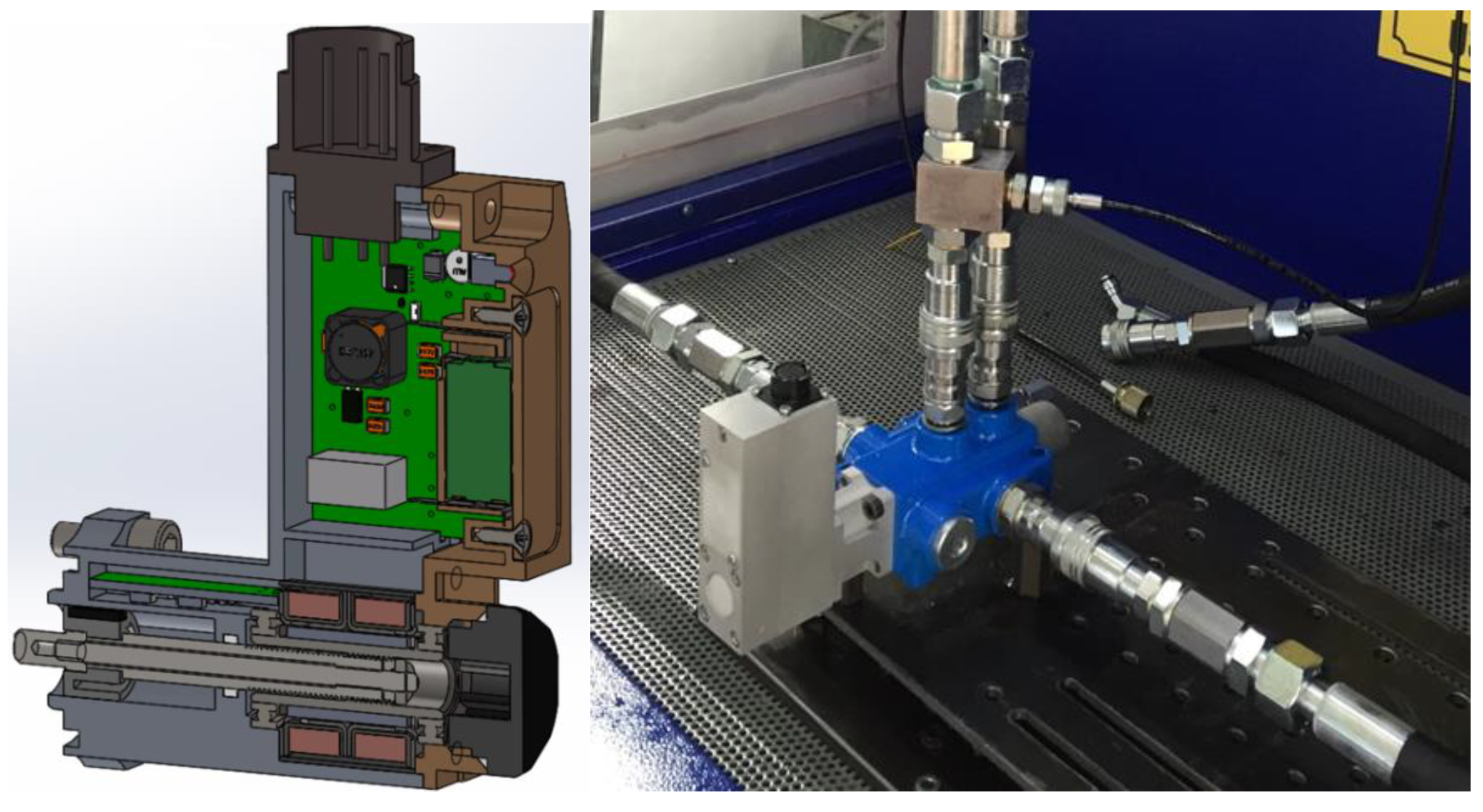
Last step is related to finishing the design. In fact, there are no significant changes to be done in the design, used in the last physical testing. The stepper motor is integrated in the complete valve assembly, including its control unit and sensor feedback. The entire design and final pre-production prototype of the system is shown in
Figure 10.
Final tests of the system show that it corresponds fully to the technical specification and the next step is to start its mass production.
6. Conclusions
Proposed methodology for development of a stepper motor design is validated through an industrial case of new design for hydraulic valve. The methodology consists of 6 steps and combines the advantages of both virtual and physical prototyping. Virtual prototyping and simulations allows to evaluate and verify the main parameters as magnetic wire (dimensions and material), permanent magnet (its strength and dimensions), as well as the current through the coil and the number of its turns.
The introduction of production technology specifics in the design is assessed step-by-step, again with physical and virtual prototypes, till reaching searched overall parameters of the entire product – step controlled hydraulic valve. It is important to note the good correlation between calculated by simulations of virtual prototype values and measured over physical prototype ones.
Presented use case is a successful demonstration of developed methodology application and it is implemented in an industrial company.
Author Contributions
Conceptualization, G.T. and K.K.; methodology, K.K.; software, B.Z.; validation, G.T. and K.K.; formal analysis, G.T.; investigation, K.K.; resources, B.Z.; data curation, B.Z.; writing—original draft preparation, K.K. and B.Z.; writing—review and editing, G.T.; visualization, B.Z.; supervision, G.T.; project administration, G.T.; funding acquisition, K.K. All authors have read and agreed to the published version of the manuscript.
Funding
This study is financed by the European Union-Next Generation EU, through the National Recovery and Resilience Plan of the Republic of Bulgaria, project № BG-RRP-2.004-0005 and by the project КП-06-Н47/8 „Research of innovative AXial induction high-efficiency MOTOrs with squirrel-cage rotor of a new generation for electric vehicles - AxMoto“.
Data Availability Statement
The data presented in this study are available on request from the corresponding author. The data are not publicly available due to relation to public funding specifics.
Conflicts of Interest
The authors declare no conflicts of interest.
References
- Szabat, K.; Pajchrowski, T.; Tarczewski, T. Modern Electrical Drives: Trends, Problems, and Challenges. Energies 2022, 15. [Google Scholar] [CrossRef]
- Ionica, I.; Modreanu, M.; Morega, A.; Boboc, C. Design and modeling of a hybrid stepper motor. In 10th International Symposium on Advanced Topics in Electrical Engineering (ATEE), Bucharest; 2017. [Google Scholar]
- Condit, R.; Jones D., W. Stepper motors fundamentals; Microchip Technology Inc, 2004. [Google Scholar]
- Tomy, N.; Francis, J. Modeling and Simulation of a Hybrid StepperMotor in Microstepping Mode. International Journal of AdvancedTechnology in Engineering 2015, 9. [Google Scholar]
- Alhinqari, A.; Alhengar, A. Simulation of Stepper Motor Motion and Control. In IEEE 1st International Maghreb Meeting of the Conference on Sciences and Techniques ofAutomatic Control and Computer Engineering MI-STA, Tripoli; 2021. [Google Scholar]
- Karadeniz, A.M.; Alkayyali, M.; Szemes, P.T. Modelling and Simulation of Stepper Motor For Position Control Using LabVIEW. Recent Innovations in Mechatronics 2018, 5. [Google Scholar] [CrossRef] [PubMed]
- Lai, C.-K.; Ciou, J.-S.; Tsai, C.-C. The Modelling, Simulation and FPGA-Based Implementation for Stepper Motor Wide Range Speed Closed-Loop Drive System Design. Machines 2018. [CrossRef]
- Kuert, C.; Jufer, M.; Perriard, Y. New method for dynamic modeling of hybrid stepping motors. In 37th IAS Annual Meeting. Conference Record of the Industry Applications Conference; 2002. [Google Scholar]
- Fei, W.; Kwong Luk, P.; Shen, J. Torque Analysis of Permanent Magnet Flux Switching Machines with Rotor Step Skewing. IEEE Transactions on Magnetics 2012, 48, 2664–2673. [Google Scholar] [CrossRef]
- Kosaka, T.; Matsui, N. Simple nonlinear magnetic analysis for three-phase hybrid stepping motors. In Conference Record of the 2000 IEEE Industry Applications Conference; 2000. [Google Scholar]
- Bernat, J.; Kołota, J.; Stepien, S. The FEM analysis of electromagnetic torque of hybrid stepper motor with different load. Przegląd Elektrotechniczny 2013, 89, 186–189. [Google Scholar]
- Kanuch, J.; Ferkova, Ž. Design and simulation of disk stepper motorwith permanent magnets. Archives of Electrical Engineering 2013, 62, 281–288. [Google Scholar] [CrossRef]
- Łukaszewicz, K. Testing Virtual Prototype of A New Product in Two Simulation Environments. Management and Production Engineering Review 2019, 10, 124–135. [Google Scholar] [CrossRef]
- Kulkarni, A.; Kapoor, A.; Iyer, M.; Kosse, V. Virtual prototyping used as validation tool in automotive design. In Proceedings of the 19th Int. Congress on Modelling and Simulation, Perth, Australia; 2011. [Google Scholar]
- Todorov, G.; Kamberov, K.; Semkov, M. Thermal CFD study and improvement of table top fridge evaporator by virtual prototyping. Case Studies In Thermal Engineering 2017, 10, 434–442. [Google Scholar] [CrossRef]
- Malakov, I.; Zaharinov, V. Optimization of size ranges of technical products. Applied Mechanics and Materials 2016, 859, 194–203. [Google Scholar] [CrossRef]
- Nedelchev, K.; Semkov, M.; Kralov, I. Geometric synthesis of fly wheel energy storage design. In AIP Conference Proceedings; 2021. [Google Scholar]
- Todorov, G.D.; Kamberov, K.H. Black box/white box hybrid method for virtual prototyping validation of multiphysics simulations and testing. IOP Conference Series: Materials Science and Engineering 2020, 878. [Google Scholar] [CrossRef]
- Santiago, G.; Hernandez CAraujo Rosa, M.; González, M. Application of product development process (PDP) in the construction of vertical axis wind turbine with movable blade. In 21st International Conference on Engineering Design, Vancouver, Canada; 2017. [Google Scholar]
- Todorov, G.; Ovcharova, J.; Romanov, B.; Kamberov, K. Interfaces for Embedding CFD Optimisation Workflows into the Product Development Process. Advanced Engineering 2010, 4, 211–222. [Google Scholar]
- Bertoni, A. Data-driven design in concept development: Systematic review and missed opportunities. In Proceedings of the Design Society: DESIGN Conference; 2020. [Google Scholar]
- Kent, L.; Snider, C.; Gopsill, J.; Hicks, B. Mixed reality in design prototyping: A systematic review. Design Studies 2021, 77, 101046. [Google Scholar] [CrossRef]
- Tseng, M.M.; Jiao, R.J.; Su CJ, J. Virtual prototyping for customized product development. Integrated Manufacturing Systems 1998, 9. [Google Scholar] [CrossRef]
- Alexandru, C. Virtual Prototyping Platform for Designing Mechanical and Mechatronic Systems. In Product Design; 2020. [Google Scholar]
- Aromaa, S. Virtual prototyping in design reviews of industrial systems. In In AcademicMindtrek'17: Proceedings of the 21st International Academic Mindtrek Conference; 2017. [Google Scholar]
- Ma, Y.; Mashal, A.; Markine, V. Modelling and experimental validation of dynamic impact in 1:9 railway crossing panel. Tribology International 2018, 208–226. [Google Scholar] [CrossRef]
- Chacon, R.; Ivantysynova, M. Virtual Prototyping of Axial Piston Machines: Numerical Method and Experimental Validation. Energies 2019, 12, 1674. [Google Scholar] [CrossRef]
|
Disclaimer/Publisher’s Note: The statements, opinions and data contained in all publications are solely those of the individual author(s) and contributor(s) and not of MDPI and/or the editor(s). MDPI and/or the editor(s) disclaim responsibility for any injury to people or property resulting from any ideas, methods, instructions or products referred to in the content. |
© 2024 by the authors. Licensee MDPI, Basel, Switzerland. This article is an open access article distributed under the terms and conditions of the Creative Commons Attribution (CC BY) license (http://creativecommons.org/licenses/by/4.0/).
