Preprint
Article

Minimum and Stable Coefficient of Thermal Expansion by Three-Step Heat Treatment of Invar 36

Submitted:

11 October 2024

Posted:

11 October 2024

You are already at the latest version

Abstract
The low coefficient of thermal expansion of Invar 36 represents a significant consideration in light of its potential effects, particularly in industrial applications where thermal stability is of paramount importance. In light of this, a three-step heat treatment was employed, to reduce the thermal expansion coefficient, and enhance the thermal dimensional stability. The ingots produced by vacuum induction melting were subjected to a warm rolling process at 900 °C, followed by a three-step heat treatment consisting of water quenching at 850 °C, tempering at 350 °C with a holding time of 1 hour, and aging at 100 °C for 24 hours. This process enabled the coefficient of thermal expansion to remain almost unchanged, exhibiting values between 0.5 and 0.6 x10⁻⁶/°C up to 150 °C. Following the heat treatment, the total elongation increased up to 40% as a natural consequence of the reduction of residual stresses, while a slight decrease in tensile strength was observed. The implementation of a three-step heat treatment process has facilitated an enhancement of the soft magnetic property, which has exhibited a decline in coercivity and an increase in saturation magnetization. As a consequence, three-step heat-treated invar 36 alloys are emerging as a potential candidate for utilization in the aerospace and precision electronics industries, given their satisfactory physical and mechanical characteristics.
Keywords: 
Subject: 
Chemistry and Materials Science  -   Metals, Alloys and Metallurgy

1. Introduction

Invar 36 is an Fe36Ni alloy that exhibits anomalous thermal expansion behavior. The term 'thermal expansion' is defined as the change in volume and shape of a material as a function of temperature. However, this phenomenon is slightly different in Invar 36. In general, the coefficient of thermal expansion (CTE) of metals and alloys is approximately 12 to 26 x10-6/°C [1,2]. However, Guillaume's 1897 report of an Fe-Ni alloy known as invar 36 with an unusually low CTE value came as a surprise to the scientific community [3]. Guillaume was awarded the Nobel Prize in Physics in 1920 in recognition of this discovery [4]. The thermal expansion of Invar 36 below its Curie temperature (230-280°C) is referred to as the Invar effect. The 'invar effect' is generally defined as spontaneous volume magnetostriction where lattice distortion counteracts normal thermal expansion [5]. The phenomenon that enables invar 36 to exhibit low CTE under the Curie temperature is the magnetic volume contraction and the magnetic moment difference of two-state austenite [6,7]. It has long been established that the anomalous thermal expansion observed in invar alloys is linked to their magnetic properties, but a complete understanding is still lacking.
Invar 36 alloys exhibit a very low CTE value between -100 and 100 °C, which renders them indispensable for a multitude of critical applications [8,9,10]. Invar 36 is the material of choice for components where precise dimensional stability of thermally is required. These include high-precision optics, liquefied natural gas (LNG) transport tanks, laser components, accelerometers, microelectromechanical systems (MEMs) and various measuring instruments, particularly in the aerospace, electronics and telescope industries. The discovery of this material has also facilitated the resolution of potential issues arising from abrupt temperature fluctuations experienced by spacecraft [11,12]. Furthermore, dimensional stability of thermally could be achieved by using molds made of invar 36 for composite material production in the aerospace industry [13].
As might be anticipated, the noteworthy thermal expansion characteristics of invar 36 are markedly influenced by the production techniques and post-production procedures employed [14,15,16]. Moreover, a variety of mechanical and thermomechanical treatments can be applied subsequent to the production of invar 36. It is important to note that these methods possess distinct advantages and disadvantages with regard to the physical and mechanical properties of the resulting invar alloys. While numerous researchers have concentrated their efforts on enhancing the mechanical properties of invar 36, the thermal expansion property is frequently compromised [17,18,19]. The addition of alloying elements to invar 36 results in damage to the lattice structure and disruption to the magnetic volume contraction mechanism. Consequently, the incorporation of additional alloying elements disrupts the magnetic interactions between Fe and Ni, influencing the magnetic volume contraction mechanism and consequently leading to an increase in the CTE. The tensile strength of invar 36 can be enhanced by up to 827 MPa through the incorporation of 4.41 wt.% Mo and 0.26 wt.% C, as demonstrated by Liu et al. through precipitation hardening [17]. Nevertheless, this resulted in a detrimental impact on the thermal expansion feature, which exhibited a notable increase from 1.54 x10⁻⁶/°C to 3.37 x10⁻⁶/°C [17]. Despite the enhancement of mechanical properties through the incorporation of alloying elements, the industry generally expects less expansion from invar 36. Consequently, the thermal expansion property of invar 36 assumes a pivotal role, superseding its mechanical properties. Moreover, there is no alternative material that can match invar 36 in terms of CTE and cost-to-performance ratio.
In light of the aforementioned circumstances, researchers have attempted to enhance the mechanical properties of invar 36 by subjecting it to severe plastic deformation (SPD), without the incorporation of alloying elements [11,14,20]. During SPD, grain refinement occurs on a nano-scale concurrently with dislocation hardening, which results in a considerable enhancement of strength [14]. The strengthening phenomenon, referred to as strain hardening, is the result of dislocation movements and dislocation formation within the crystalline structure of the material. It is widely acknowledged that grain boundaries represent regions where the motion of dislocations is restricted. Moreover, it is observed that dislocations interact with each other at grain boundaries, leading to their aggregation in these regions. As a consequence of SPD, the material's strength was enhanced due to a reduction in grain size to the nanoscale level by the formation of new grains throughout the recrystallisation process. Vinogradov et al. successfully produced ultrafine grains (160-200 nm after 12 pressing) via equal-channel angular pressing (ECAP) [14]. A reduction in grain size from 100 µm to 0.18 µm was observed to result in an increase in tensile strength from 490 MPa to 912 MPa [14]. Vinogradov et al. did not examine the CTE property, but Bitkulav et al. addressed this gap in the existing literature. Bitkulav et al. determined the CTE value of invar 36 with a grain size of approximately 0.1 µm as 0.7 x10⁻⁶/°C, where severe plastic deformation was applied [20].
It is well established that materials that have undergone significant plastic deformation tend to exhibit elevated dislocation densities and residual internal stresses. These characteristics are believed to impede thermal expansion to a certain degree [8,20]. The vibration harmony of the lattices during thermal expansion is not uniform due to the presence of excessive residual stresses and dislocations, which also contribute to a reduction in the CTE. Bitkulov et al. applied an annealing treatment at temperatures approximating 350 °C to remove the residual stresses, resulting in a sudden increase in the CTE up to 2.4 x10⁻⁶/°C [20]. A sudden increase in the amount of thermal expansion was observed, which was attributed to the release of residual stresses and/or rearranged dislocations under the influence of temperature [20]. Such abrupt fluctuations give rise to a thermally unstable and unreliable state of affairs, particularly in applications of great consequence within the aerospace industry.
A detailed evaluation of these issues, coupled with an understanding of the demands placed upon the industry, reveals a clear requirement for an invar 36 that exhibits both thermally stable and a low CTE. It is recognized that the application of a three-step heat treatment process to invar alloys enhances thermal stability. However, the impact of this heat treatment process on mechanical and physical properties has been subjected to comprehensive investigation for the first time. In this context, the CTE, microstructure, crystallographic structure, magnetic properties and also mechanical properties such as hardness and tensile strength of the three-stage heat treatment were subjected to a comprehensive discussion, and compared with the existing literature.

2. Materials and Methods

The samples were prepared using a VAC-LONG VISM-5 vacuum induction melting (VIM) system with a 5 kg capacity, operating under a vacuum of 10-2 mbar and a partial argon gas pressure of 100 mbar. The alloy was formed using high-purity (99.99%) Ni, AISI 1008 steel. To circumvent casting cavity defects and their subsequent manifestation as rolling cracks, the castings were produced in graphite molds that were heated to 800 °C. The chemical compositions of the as-cast ingots (as detailed in Table 1) were determined using a Bruker S2 PUMA X-ray fluorescence (XRF) spectrometer.
Ingot samples with casting dimensions of 40 x 20 mm were warm rolled at 900 °C to a thickness of 10 mm, which corresponds to a rolling ratio of 2:1. As illustrated in Figure 1, the three-step heat treatment was conducted subsequent to the warm-rolling process. The initial stage of the three-step heat treatment process entails subjecting the samples to a temperature of 850 °C for a period of one hour, after which samples were rapidly cooled in water. The second stage of the process, referred to as tempering, involved subjecting the samples to a heating cycle, reaching a temperature of 350 °C for a period of one hour, and then allowing them to cool in a controlled air environment. The final stage of the process was the ageing phase, which involved subjecting the samples to a temperature of 100 °C for a period of 24 hours, followed by furnace cooling. In the course of this study, four samples were prepared and coded as AC, ACWR, ACQT, and ACA, as listed in Table 1.

2.2. Characterization

Samples for microstructural observation were taken from cross-sections of the ingots. Subsequent to grinding and polishing, the samples were etched with a Marble solution (comprising 50 ml HCl, 10 g CuSO4 and 50 ml water) for 25 second. The grain size of the samples was analyzed using a ZEISS Axioskop 2 MAT optical microscope. Scanning electron microscopy (SEM) coupled with energy-dispersive X-ray spectroscopy (EDS) was employed to analyze the samples. This was conducted on a Tescan MIRA 3 high-resolution field emission scanning electron microscope (HR-FE-SEM) equipped with an EDX detector. This enabled an analysis of the elemental composition of the samples. The crystal structural properties of the as-prepared ingots were examined using a Rigaku MiniFlex 600 X-ray diffractometer (XRD) with Cu-Kα radiation at a scan rate of 2.5°/min. Microhardness measurements were conducted using a Metkon Duroline micro tester on microstructure samples from a minimum of five points in accordance with the Vickers HV5 method, with a load of 5 kgf (49.1 N). Tensile tests were conducted at room temperature utilizing a Zwick/Roell Z100 universal testing machine, in accordance with the ASTM E8 standard. The thermal expansion properties of machined samples (diameter of 5 mm and a length of 20 mm) were evaluated using a Linseis L75 Platinum Series Dilatometer. The temperature range was set to 20–300 °C, with a heating rate of 3 °C/min, in accordance with the ASTM E228-17 standard. The CTE of the samples was calculated in accordance with the following CTE calculation principle (Equation 1), which is based on the push-rod horizontal dilatometer method.
L = α L 0 T
Where L is the change in length, α is the coefficient of thermal expansion, L 0 is the original length and T is the change in temperature. The magnetic properties were analyzed using Quantum Design DynaCool-9 vibrating sample magnetometry (VSM) at room temperature.

3. Results and Discussion

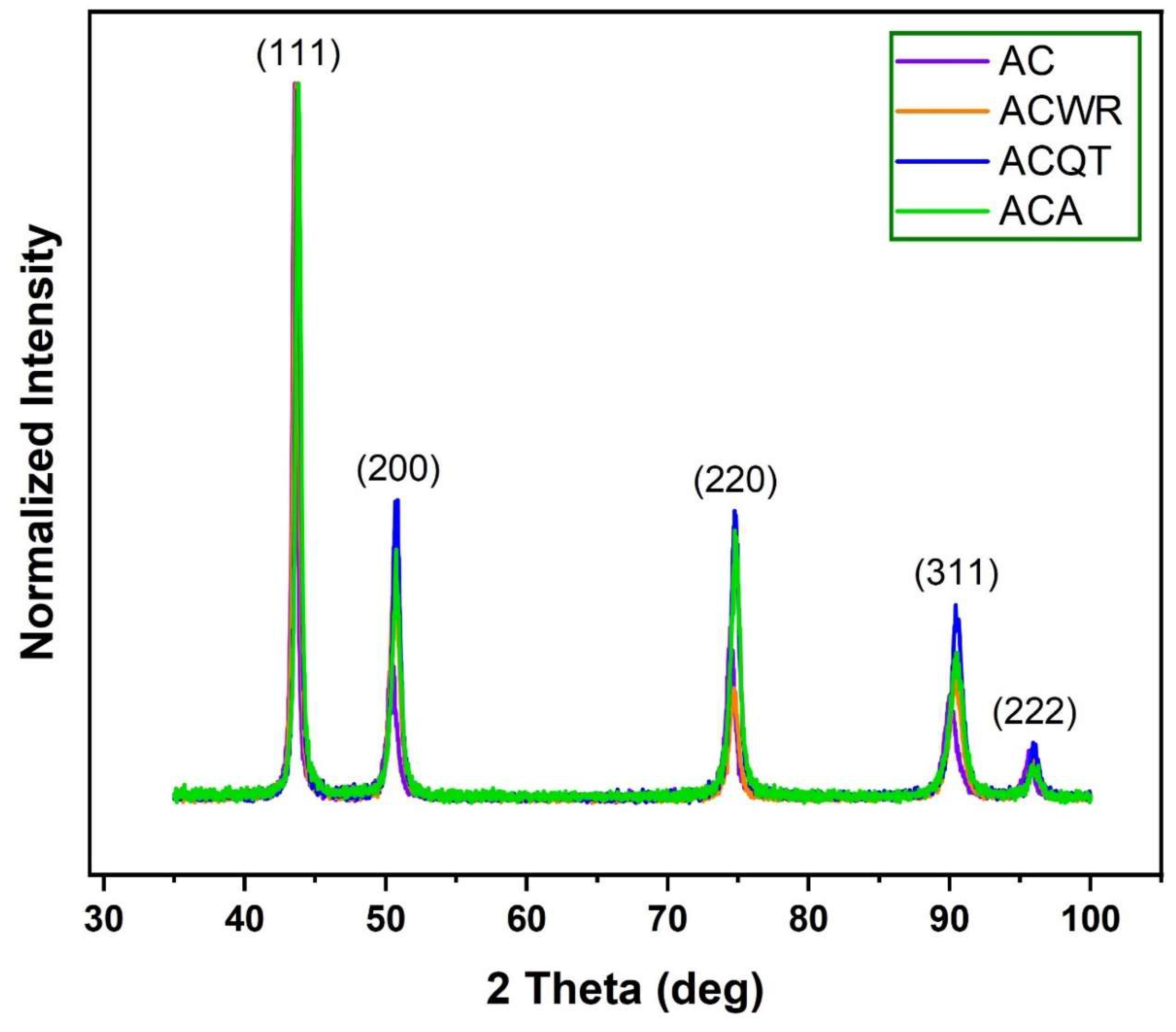
Figure 2 illustrates the X-Ray diffraction (XRD) results of the samples. As expected, all samples exhibit classical austenite (γ-Fe) XRD peaks, with the strongest diffraction peaks being primarily γ(111), γ(200), γ(220), γ(311) and γ(222). It has been demonstrated in the existing literature that the thermal expansion feature is significantly impaired if the austenitic structure undergoes a deviation from its original state [17]. The austenite peaks were found to be strongest along the (111) plane, which is also the most thermodynamically stable plane in metals with a face-centered cubic (FCC) lattice structure [22]. This is due to the lower surface energy compared to other planes [23,24]. Conversely, no peaks apart from those of austenite were observed in the XRD pattern. The elevated Ni content (36%) in invar 36 serves to stabilize the austenite phase of this unique alloy up to room temperature [25,26,27]. It is common knowledge that alloying elements such as nickel (Ni) and manganese (Mn) added to iron (Fe) are highly effective in stabilizing austenite. In particular, in materials with the FCC structure, a concentration of Ni exceeding 7% is sufficient to stabilize the austenite phase even at relatively low temperatures [26,28].
The normalized XRD pattern is employed to compare relative peak intensities. The relative intensity variations of the samples outlined in Table 2 were determined by calculating the intensity ratio of the maximum peak (111). It can be observed that the relative intensities of thermodynamically stable planes, such as (111), were higher in all samples. In general, FCC metals are crystallized during solidification in the preferred directions, which is the further intensity of the atoms, in order to minimize surface energy [22]. It can therefore be concluded that the (111) crystal plane, which exhibits the lowest surface energy, is thermodynamically dominant in all cases.
It can be observed that the diverse crystal planes are oriented in a manner that is influenced by a recrystallisation and twin effect resulting from hot deformation, as well as a three-step heat treatment effect [29]. A comparison of AC and ACWR samples revealed a notable increase in the intensity of peak (200), accompanied by a reduction in the intensity of peak (220) and a lack of significant change in the intensity of other peaks. These observations can be attributed to the recovery and dynamic recrystallisation of the metal microstructure, which occur as a result of temperature and force during warm forming, leading to enhanced diffusion kinetics [30,31]. In contrast to the process of static recrystallisation, dynamic recrystallisation involves the nucleation and growth of new grains occurring during the deformation stage, rather than subsequent to deformation as part of a separate heat treatment [32]. Dynamic recrystallisation (DRX) represents a phenomenon that occurs during the process of straining and is typically observed in materials with low or medium stacking fault energy, including copper, gamma iron, and austenitic steels [33,34].
It is important to note that no complete recovery and recrystallisation occurred following warm rolling. This is because, although the rolling process is carried out at a relatively high temperature, additional heat treatment is necessary for complete recrystallisation and stress relief for minimum CTE in accordance with ASTM standards [35]. As illustrated in Table 2, the intensity of (200), (220) and (311) exhibited a notable enhancement following the water quenching from 850 °C and tempering at 350 °C, which represents the initial two stages of the three-step heat treatment. It can be concluded that the observed changes in XRD peak intensities are also related to the preferential rotation of the grains during the rolling process and three-step heat treatment. This can be attributed to the effects of diffusion and force. It is well established that the energy stored in the deformed regions of various grains is the primary driving force behind recrystallisation during annealing [36]. The formation of new crystals during annealing is accompanied by a preferential orientation, which results in an increase in the density of specific planes.
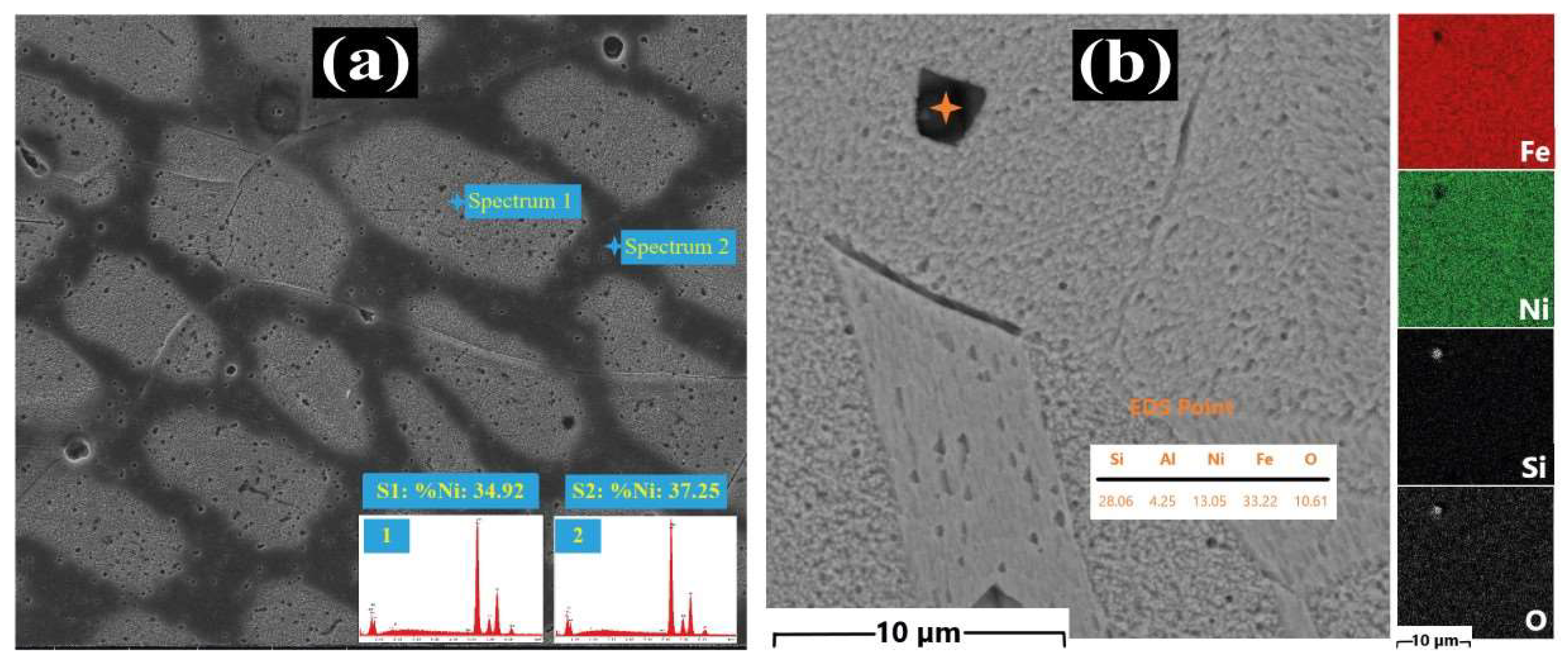
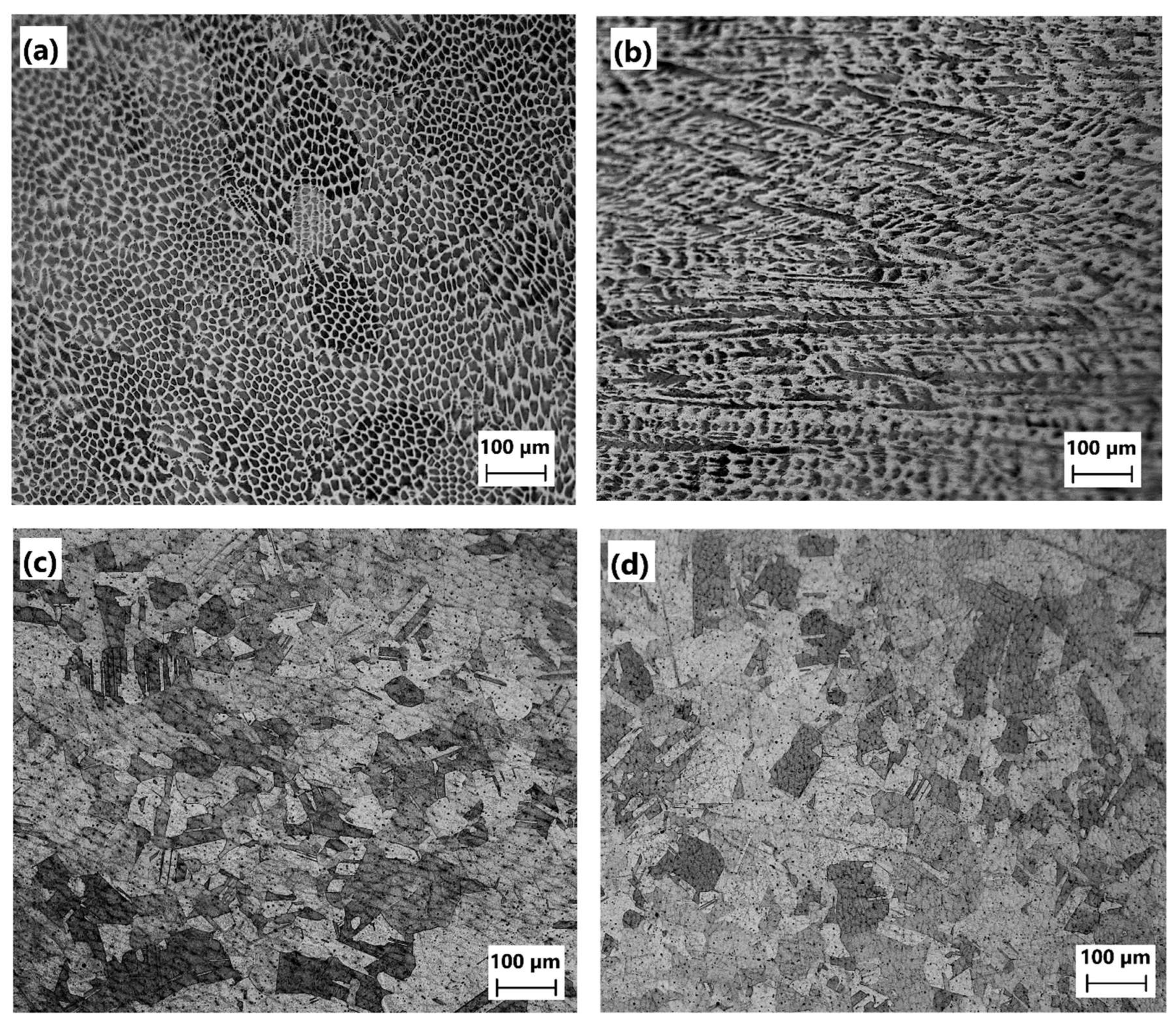
Figure 3 illustrates the optical microscope images of the samples cast in graphite molds and subsequently subjected to secondary processes, including warm rolling and three-step heat treatment. Figure 3(a) displays microcellular structures that closely resemble sub-grain structures after casting. The formation of microcellular structures can be facilitated by the influence of relatively rapid solidification. Such structures are regarded as indicative of micro-segregation of nickel in high nickel alloys, as documented in literature sources [37,38]. Figure 6(a) presents the findings of the EDS spectral analysis of the inner and outer regions of these microcellular structures. The data indicates a notable discrepancy in the nickel ratio between the two regions, with the inner regions exhibiting a relatively low nickel ratio and the outer regions displaying a higher nickel ratio. However, the Ni range of invar 36, as defined by the ASTM standard, is between 35% and 37%, and therefore it is deemed that this will not have a significant impact on the properties of invar 36.
Figure 3(b) illustrates the microstructure of the warm-rolled specimen at 900 °C. The effect of warm-rolling causes the grains to orientate themselves in the direction of rolling, akin to dough, and facilitates the spread of microcellular structures. It can be generally stated that due to the high-temperature rolling of invar 36 (between 1100 and 1200 °C), the grains formed subsequently exhibit an absence of microcellular structures [39,40]. The microstructure of invar alloys rolled at these temperatures (1100–1200 °C) displays the presence of more prominent grains and twins. This is due to the sufficient temperature for recrystallisation occurring after the deformation process at high temperature, which allows for easy crystallization until cooling occurs. Accordingly, following warm rolling at 900 °C, no discernible grain or twin is observed in Figure 3(b). However, it should be noted that the dislocation densities and residual stresses in the warm rolling process are considerably higher than in the hot rolling process. The orientated microstructure and the increased dislocation density that result from warm rolling can provide additional nucleation sites along grain boundaries, thereby enhancing the driving force for recrystallisation during annealing [36,41].
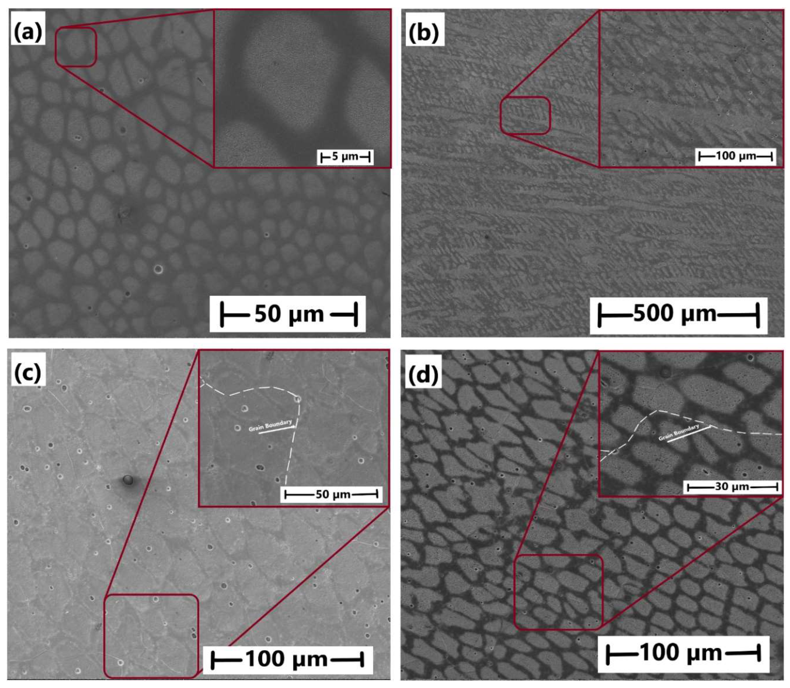
In order to facilitate recrystallisation and achieve a more uniform microstructure, a water-quenching process was conducted at 850 °C for one hour and a tempering process was performed at 350 °C for one hour to eliminate residual stresses. The resulting microstructure is illustrated in Figure 3(c). Relatively equiaxed grains and annealing twins were formed. Some of the grains observed in ACQT specimens are approximately 100 µm in size, while the majority of grains are approximately 50 µm. It can be stated that the microcellular structures, which were spread out following warm rolling, were reappeared in a specific sequence after the tempering process, resulting in a relatively hexagonal structure. However, this is not as clearly discernible when compared to the AC sample. As a consequence of the enhanced diffusion facilitated by the heat treatment, the segregation of Ni was found to have decreased. Conversely, it can be asserted that the grains became slightly coarser as a consequence of stabilization ageing at 100 °C for 24 hours. Despite the relatively low temperature for grain coarsening, the extended period may have provided an environment conducive to diffusion. Consequently, it is evident that the microcellular structures observed in the microstructure after casting diminished following the tempering and ageing processes.
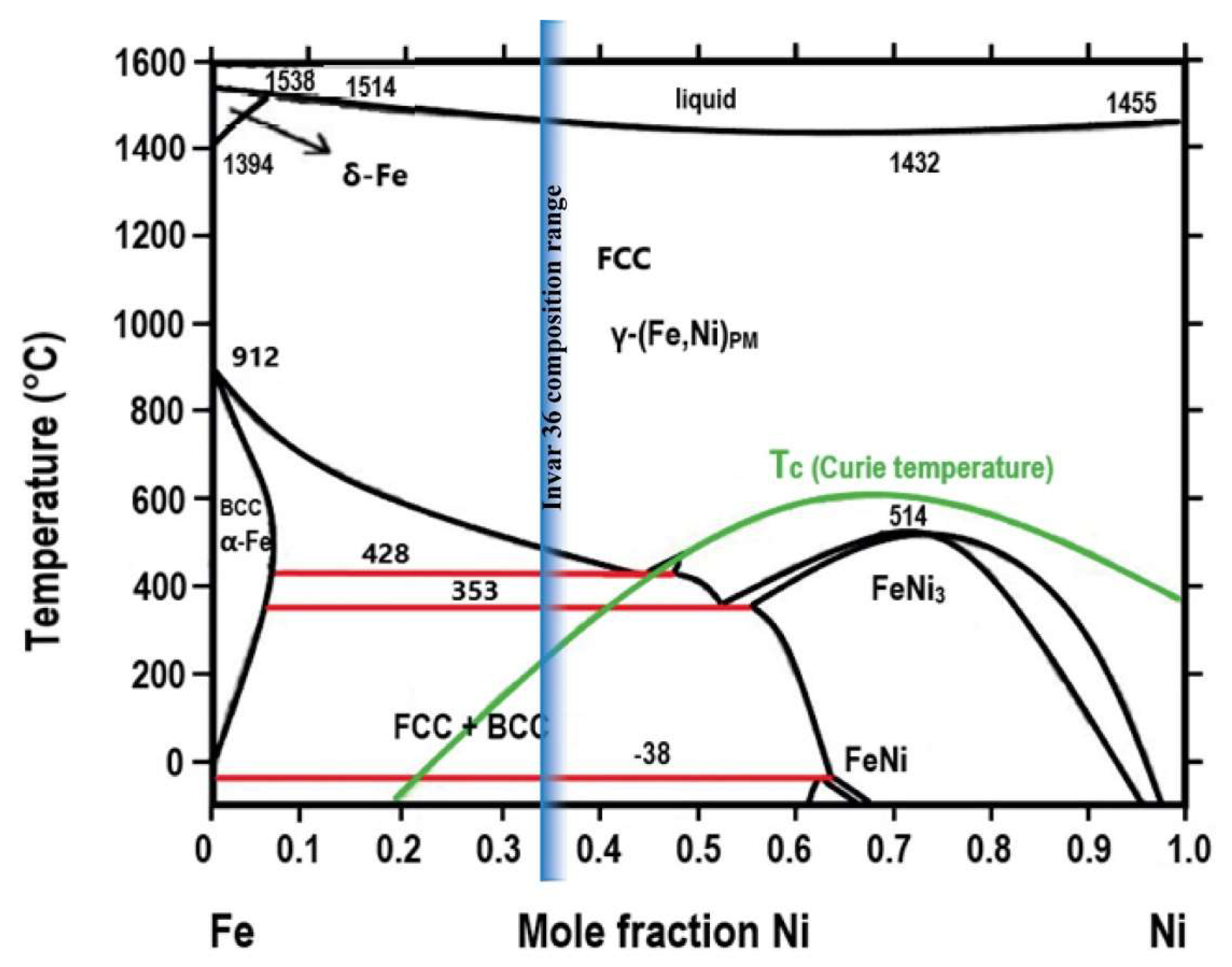
It is widely acknowledged that the mechanical and physical properties of materials are correlated with their bonding energy, lattice structure, microstructure and morphology [38,42,43]. The segregation of nickel can occur in high-nickel alloys, depending on the cooling conditions and the cooling rate. Given that the enthalpy of solidification is negative, it follows that heat will be released along the solid-liquid interface, with the consequence that the temperature of the liquid will be locally increased [38]. In addition, it is known that the concentrations of the liquid and solid phases comply with the solidus and liquidus lines on the phase diagram during the process of solidification. It should be noted that both solidus and liquidus line are subject to change with temperature. Upon solidification of invar 36, the primary austenite phase is initially formed from the liquid phase (liquid + primary austenite), followed by the development of the final austenite phase [44]. It is important to note, however, that due to the differing solubility of Ni in the austenite phase and the liquid phase, the composition of the primary austenite and the liquid phase will be different when the primary austenite is formed in the liquid. In such a case, the liquid phase will be richer in Ni than the primary austenite.
Figure 4. The Fe-Ni phase diagram adopted from [38].
Preprints 120945 g004
As evidenced by the EDS analyses presented in Figure 5(a), the microcellular regions where Ni segregation occurs are Ni-poor regions, a finding that aligns with the observations reported by Chen et al. [37]. Figure 5 illustrates the diverse morphological states of microcellular structures that resemble "cobblestone" and are embedded in austenite grains. Following casting (Figure 5(a)), the microcellular structures, with an average size of 5 μm, were observed to disperse after warm rolling (Figure 5(b)). After undergoing a three-stage heat treatment (Figure 5(c and d)), the microcellular structures exhibited a coaxial structure and a size of approximately 20 μm. In the study conducted by Chen et al., the dimensions of these subcellular structures were approximately 50 μm [37]. Conversely, following the tempering and ageing processes, the formation of inclusion-like microparticles became a prominent feature. The results of the EDS analyses of these particles are presented in Figure 6(b).
The microparticles observed in the microstructure, measuring 1-2 µm in size, were identified as SiO2 through EDS spot and mapping analyses. Additionally, Al was detected in an EDS point analysis. This suggests that these particles may have been contaminated into the liquid metal from an alumina-silicate based melting crucible. During the induction melting process, the liquid metal, which is continuously mixed under the influence of induction currents, may naturally erode the alumina-silicate-based crucible to a certain extent. Conversely, the EDS point analysis (Figure 6(a)) revealed that the spectral analyses of the Ni element in the inner and outer regions of the cellular structures indicated Ni segregation resulting from relatively rapid cooling. Consequently, the Ni ratio of 34.92% in the inner region (Spectral 1) is 37.25% in the outer regions (Spectral 2). The mean Ni content is approximately 36%. Given that the cooling rate of graphite molds employed in ingot casting is approximately 100 times higher than that of conventional sand molds (SiO2), it is to be expected that Ni segregation may occur [45,46].
Figure 6. EDS point and mapping analysis.
Preprints 120945 g006
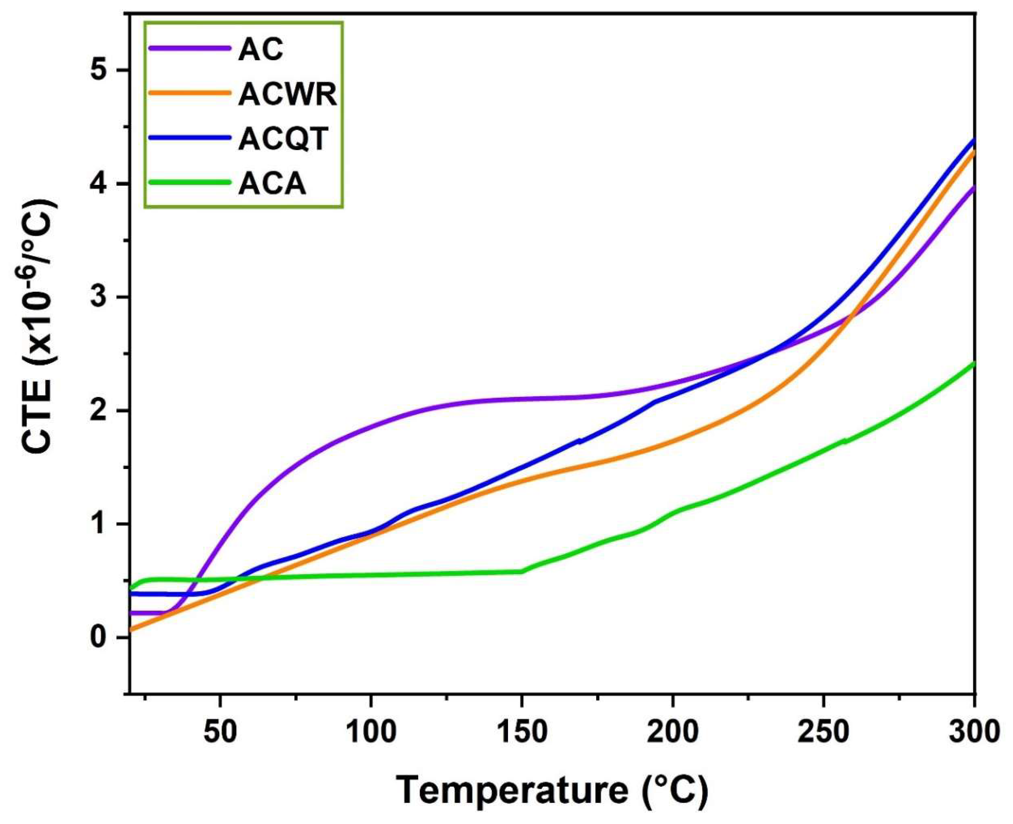
Figure 7 displays the impact of the three-step heat treatment process on the CTE. In this context, it is evident that the CTE exhibits a notable decline following warm rolling after casting, particularly within the temperature range of 20–150 °C. While the CTE value of the AC sample was 2.100 x10⁻⁶/°C within the aforementioned temperature range, it decreased to 1.378 x10⁻⁶/°C in the ACWR sample with warm rolling. This situation can be addressed through two distinct approaches. The residual stresses and severe dislocation densities that emerge following warm rolling served to impede lattice vibration and atomic mobility. Consequently, the higher dislocation densities and residual stresses that are generated by warm rolling contribute to a reduction in the CTE by limiting lattice vibrations [38,47]. This may be the reason for the reduction in CTE associated with the warm rolling process. In accordance with the invar theory, the low CTE characteristic of invar 36 is predominantly a consequence of magneto-volume contraction. However, lattice vibrations are inherently present and contribute to its thermal expansion [38,47]. The effects of residual stresses and excessive dislocation densities associated with warm rolling can be observed in both magnetic volume contraction and thermally induced lattice expansion. Additionally, these effects can alter the interatomic distance and disrupt the balance within the magnetic lattice structure, subsequently influencing exchange interspine interactions [48].
It is acknowledged that there was a distinction between the as-cast (AC) interatomic distance and the warm-rolled (ACWR) interatomic distance. In light of the fact that any micro-porosity that may have formed during the casting process was sealed after warm rolling, it is possible that the equilibrium within the magnetic lattice structure and, consequently, the exchange interspine interactions underwent a change [49]. This conclusion is supported by the variation of the intensities of the XRD diffraction peaks resulting from the preferential plane orientation caused by warm rolling, as illustrated in Table 2. These discrepancies in the crystal planes impact the lattice vibration and atomic mobility, which in turn influence the CTE since the elasticity of each crystalline structure is unique [50]. It is well established that thermally induced expansion is dependent upon the thermal stress and elastic stretching of the crystal lattice [50]. Furthermore, the thermal expansion is typically low in directions where the elastic modulus is high. In general, preferential orientations tend to occur in specific crystal-dependent planes, where sliding is more readily facilitated [51]. It can be inferred that as a consequence of this, isotropic CTE behavior may have emerged across a range of warm rolling directions.
It is important to note, however, that residual stresses and excessive dislocation densities distorted the specific magnetic lattice structure of the invar 36, thereby compromising its dimensional stability. It is possible that the rolling process led to a slight variation of the interatomic distance, which could potentially disrupt the equilibrium within the magnetic lattice structure and contribute to the exchange of interspine interactions (Fe-Fe, Fe-Ni and Ni-Ni) [48]. The magneto-lattice effect is a phenomenon arising from the interactions between the magnetic moments of Fe and Ni atoms within the lattice. Although there has been a slight reduction in the CTE compared to the as-cast form, an invar 36 free from internal stresses is more reliable and thermally stable. Indeed, the CTE value observed in Figure 7 after three-step heat treatment, which is both low and thermally stable up to ~150 °C, represents the optimal result that can be expected from invar 36. A review of the data presented in Table 3 reveals that the ACA example exhibits the most favorable CTE values. Its thermal dimensional stability remains remarkably consistent, exhibiting minimal fluctuations between a CTE value of 0.5 and 0.6 x10⁻⁶/°C up to 150 °C. This can be attributed to the residual stresses released in the material after the three-step heat treatment and the excessive dislocation densities removed. This is due to the fact that the lattice vibrations of invar 36, which vibrate and expand with temperature, are counteracted by magneto volume contraction associated with the two-state austenite model [6,7,38]. It can be reasonably deduced that the magnetic volume contraction mechanism operates more effectively in an austenite crystal that is devoid of residual stresses and dislocations. Consequently, the ACA sample, lowest in residual stresses and dislocation densities, showed the minimum CTE, and was the most stable, thereby establishing itself as a candidate material that is reliable and fit for purpose within the industry.
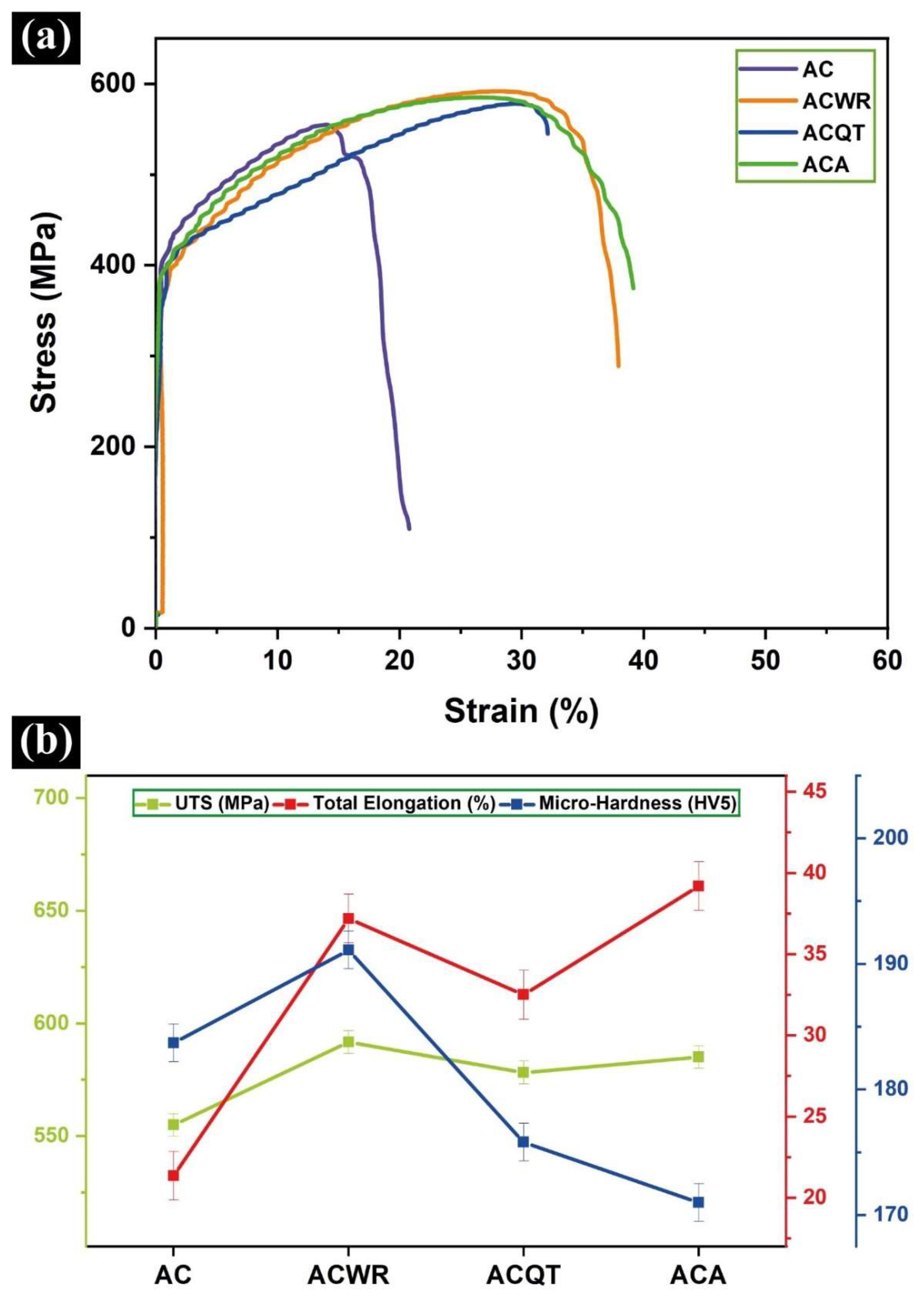
Figure 8(a and b) illustrates the tensile strength and hardness results. The lowest tensile strength was recorded at 555 MPa in the sample following casting. Following warm rolling at 900 °C, an increase of approximately 40 MPa in tensile strength was observed. The maximum tensile strength of 592 MPa was attained in the warm rolled specimen. It is widely acknowledged that defects, such as micro-shrinkage or gas cavities, can frequently manifest themselves following the casting process [55]. The aforementioned casting defects have the potential to act as stress accumulating centers during tensile testing [55]. It can be seen in Figure 8 that the occurrence of a sudden failure with a minimal amount of elongation could potentially occur unexpectedly. The mechanical deformation applied by warm rolling was found to increase the tensile strength of the material. This increase can be attributed to the inhibition of dislocation motions by grain boundaries and/or discontinuities, such as twins and inclusions. Additionally, as illustrated in Figure 8, the strain hardening mechanism contributed to the enhancement of the mechanical properties.
Conversely, the total elongation value following casting was relatively low at 21%. As previously stated, the micro voids that are likely to be present following casting have had a detrimental impact on the total elongation, resulting in a total elongation of all samples following warm rolling that exceeds the 30% band. In particular, at the conclusion of the three-step heat treatment, the ACA sample exhibited a notable enhancement in total elongation, reaching 40% due to the combined influence of reduced dislocation densities and residual stresses, in addition to recrystallisation within the microstructure. Although there was no significant change in tensile strength following the tempering and ageing processes, a minor decrease was identified. The microhardness assessments revealed that the warm rolled specimen exhibited the highest value, reaching 191 HV. A reduction in hardness was noted as a consequence of the release of residual stresses through the tempering and ageing processes, in addition to a decline in dislocation densities. This resulted in a microhardness value of 171 HV after the ageing period. However, it is important to highlight that this value remains within the ASTM standards, making it a favorable candidate for CTE.
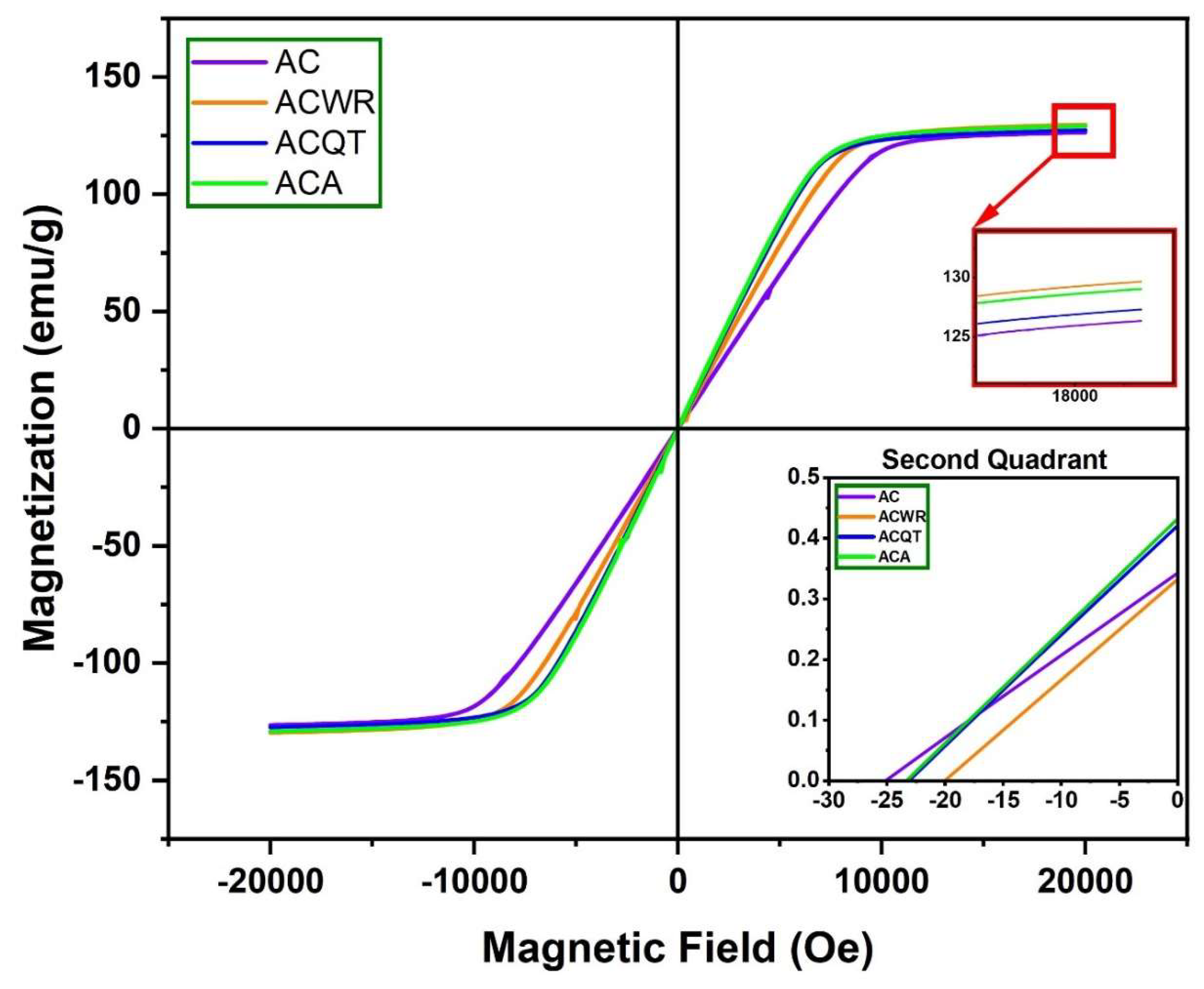
Figure 9 illustrates the magnetic field versus magnetization hysteresis loop (M-H loop), which demonstrates the magnetic properties of the samples, as well as the second quadrant and magnetic saturation region, indicating coercivity. In general, all samples exhibited soft magnetic properties, as anticipated when the characteristics of the M-H loop curves are analyzed. The results demonstrated that all of the samples exhibited magnetic properties consistent with those reported in the literature [56,57,58]. Although there was no significant change in saturation magnetization (Ms) values, warm rolling and three-step heat treatment processes contributed to the improvement of Ms from 126 emu/g to 130 emu/g. Ms value has an important place in invar alloys as it shows the magnetization ability of materials. The Ms value of 130 emu/g obtained in the ACWR sample was much higher compared to other similar materials reported in the literature (100, 90 and 73 emu/g) [57,58,59].
Saturation magnetization is a significant parameter for soft magnetic applications, as high values permit the miniaturization of industrial components. Consequently, in applications such as accelerometers utilized in the aerospace industry, it is advantageous for the material to exhibit rapid magnetization and demagnetization when required. The ability to demagnetize quickly is also related to the coercivity, which showed a slight decrease with three-step heat treatment without a significant change. The coercivity values of the samples were found to vary between 20 Oe and 25 Oe, in accordance with the literature [60,61]. It is widely known that low coercivity values indicate that the material can be readily demagnetized. Consequently, the sensitivity of accelerometers utilized in aerospace technologies is enhanced due to diminished energy losses and improved efficiency. The rise in magnetic saturation and decline in coercivity can be attributed to the magneto-crystalline anisotropy effect with decreasing grain size [57].

4. Conclusions

The effects of three-step heat treatment and warm-rolling on the microstructure, mechanical, and physical properties of invar 36 were investigated in depth.
  • All samples exhibited classical austenite (γ-Fe) XRD peaks, with the strongest diffraction peaks being primarily γ(111), γ(200), γ(220), γ(311) and γ(222). The relative intensities of thermodynamically stable planes, such as (111), were observed to be higher in all samples. It is noteworthy that the intensity of peak (200) increased significantly, while the intensity of peak (220) decreased and the intensity of the other peaks remained relatively unchanged during the warm rolling process.
  • The casting process resulted in the formation of microcellular structures that exhibited a resemblance to sub-grain structures. The formation of microcellular structures can be facilitated by the influence of relatively rapid solidification. The microcellular regions in which Ni segregation occurs are distinguished by the presence of Ni-poor regions and encompass the diverse morphological states of microcellular structures that resemble "cobblestones" embedded in austenite grains.
  • The most favorable result that could be expected from Invar 36, which displays both minimal thermal expansion and thermally stable properties up to ~150 °C, was observed in the sample that underwent a three-step heat treatment. The material displays remarkable consistency in its dimensional stability of thermally, exhibiting minimal fluctuations in its coefficient of thermal expansion (CTE) value between 0.5 and 0.6 x10⁻⁶/°C up to 150 °C.
  • Following the application of warm rolling at 900 °C, an increase of approximately 40 MPa in tensile strength was observed. The warm-rolled specimen exhibited the highest tensile strength, reaching 592 MPa. The total elongation value after casting was relatively low at 21%, which is likely due to the presence of micro voids after casting, which have had a detrimental impact on the total elongation. The conclusion of the warm rolling and three-step heat treatment resulted in a notable enhancement in total elongation, reaching 40%, which can be attributed to the combined influence of reduced dislocation densities and residual stresses, in addition to recrystallisation within the structure.
  • All samples exhibited soft magnetic properties. The saturation magnetization (Ms) was observed to increase from 126 emu/g to 130 emu/g as a consequence of the warm rolling and three-step heat treatment processes. The coercivity values of the samples were found to vary between 20 and 25 Oe.

Author Contributions

Mehmet Kul: Conceptualization, Methodology, Validation, Formal analysis, Resources, Data curation, Writing – review & editing, Supervision, Project administration. Bekir Akgül: Writing – original draft, Writing – review & editing, Methodology, Validation, Formal analysis, Investigation, Visualization. Yusuf Ziya Karabay: Validation, Formal analysis, Investigation, Review & editing. Leonhard Hitzler: Validation, Review & editing. Enes Sert: Validation, Review & editing. Markus Merkel: Validation, Review & editing.

Funding

This research is supported by the Scientific and Technological Research Council of Türkiye (TUBITAK) (Grant No. 123M286).

Data Availability Statement

All data are available on request to the corresponding author.

Acknowledgments

The authors are grateful for the fellowship support of the TÜBİTAK Directorate of Science Fellowships and Grant Programs (BİDEB).

Conflicts of Interest

The authors declare that they have no known competing financial interests or personal relationships that could have appeared to influence the work reported in this paper.

References

  1. Nie, Q.; Chen, G.; Wang, B.; Yang, L.; Zhang, J.; Tang, W. Effect of Invar Particle Size on Microstructures and Properties of the Cu/Invar Bi-Metal Matrix Composites Fabricated by SPS. J. Alloys Compd. 2022, 891, 162055. [CrossRef]
  2. Nyanor, P.; El-Kady, O.; Yehia, H.M.; Hamada, A.S.; Hassan, M.A. Effect of Bimodal-Sized Hybrid TiC–CNT Reinforcement on the Mechanical Properties and Coefficient of Thermal Expansion of Aluminium Matrix Composites. Met. Mater. Int. 2021, 27, 753–766. [CrossRef]
  3. Guillaume, C.E. Recherches Sur Les Aciers Au Nickel. Dilatations Aux Temperatures Elevees; Resistance Electrique. C. R. Acad. Sci. Paris 1897, 125, 235–238.
  4. Guillaume, C.-É. Invar and Elinvar. Nobel Lect. Phys. 1901-1921, 1920.
  5. Van Schilfgaarde, M.; Abrikosov, I.A.; Johansson, B. Origin of the Invar Effect in Iron-Nickel Alloys. Nature 1999. [CrossRef]
  6. Roy, D.M.; Pettifor, D.G. Stoner Theory Support for the Two-State Hypothesis for γ Iron. J. Phys. F Met. Phys. 1977. [CrossRef]
  7. Weiss, R.J. The Origin of the “invar” Effect. Proc. Phys. Soc. 1963. [CrossRef]
  8. Kul, M.; Akgül, B.; Karabay, Y.Z.; Pehlivanoğlu, K.; Türkyaman, B. A Study of the Effect of Ti-Al-V Microalloying on the Mechanical and Physical Properties of Invar 36. Mater. Today Commun. 2024, 39, 109050. [CrossRef]
  9. Konovalov, S.F.; Mayorov, D. V.; Semenov, A.E.; Ponomarev, Y.A.; Chulkov, V.E.; Malykhin, A.A.; Kharlamov, M.S.; Malykhin, D.A. Temperature Drift and Instability of a Zero Signal of Pendulum Compensating Q-Flex Accelerometer. 27th Saint Petersbg. Int. Conf. Integr. Navig. Syst. ICINS 2020 - Proc. 2020. [CrossRef]
  10. Kim, D.S.; Pyo, C.; Kim, J.; Kim, J.; Lee, H.K. A Study on Cross-Shaped Structure of Invar Material Using Cold Wire Laser Fillet Welding (PART I: Feasibility Study for Weldability). Met. 2020, Vol. 10, Page 1385 2020, 10, 1385. [CrossRef]
  11. Sokolowski, W.M.; Jacobs, S.F.; Lane, M.S.; O’Donnell, T.P.; Hsieh, C. Dimensional Stability of High-Purity Invar 36. In Proceedings of the Quality and Reliability for Optical Systems; Bilbro, J.W., Parks, R.E., Eds.; December 7 1993; pp. 115–126.
  12. NASA Turbopump Systems for Liquid Rocket Engines. NASA Sp. Veh. Des. Criteria (Chemical Propulsion) 1974.
  13. Wang, C.-S.; Wang, Y.-M. DURABLE TOOL FORMOLDING OF POLYMER COMPOSITES 2008, 1–5.
  14. Vinogradov, A.; Hashimoto, S.; Kopylov, V.I. Enhanced Strength and Fatigue Life of Ultra-Fine Grain Fe-36Ni Invar Alloy. Mater. Sci. Eng. A 2003. [CrossRef]
  15. Chen, C.; Huang, Y.L.; Yao, Y.F.; Fu, X.K.; Li, W.; Hou, Y.H. Effects of Thermal Annealing on Improved Magnetic Properties and Microstructure for SmFe11Ti Alloy. J. Magn. Magn. Mater. 2021, 530, 9–13. [CrossRef]
  16. Wegener, T.; Brenne, F.; Fischer, A.; Möller, T.; Hauck, C.; Auernhammer, S.; Niendorf, T. On the Structural Integrity of Fe-36Ni Invar Alloy Processed by Selective Laser Melting. Addit. Manuf. 2021. [CrossRef]
  17. Liu, H.; Sun, Z.; Wang, G.; Sun, X.; Li, J.; Xue, F.; Peng, H.; Zhang, Y. Effect of Aging on Microstructures and Properties of Mo-Alloyed Fe–36Ni Invar Alloy. Mater. Sci. Eng. A 2016, 654, 107–112. [CrossRef]
  18. Sui, Q.S.; Li, J.X.; Zhai, Y.Z.; Sun, Z.H.; Wu, Y.F.; Zhao, H.T.; Feng, J.H.; Sun, M.C.; Yang, C.L.; Chen, B.A.; et al. Effect of Alloying with V and Ti on Microstructures and Properties in Fe–Ni–Mo–C Invar Alloys. Materialia 2019. [CrossRef]
  19. Ha, T.K.; Min, S.H. Effect of C Content on the Microstructure and Physical Properties of Fe-36Ni Invar Alloy. Mater. Sci. Forum 2014, 804, 293–296. [CrossRef]
  20. Bitkulov, I.K.; Burkhanov, A.M.; Kazantsev, V.A.; Mulyukov, R.R.; Mulyukov, K.Y.; Safarov, I.M. Effect of Severe Plastic Deformation on the Properties of the Fe-36% Ni Invar Alloy. Phys. Met. Metallogr. 2006, 102, 91–96. [CrossRef]
  21. Manufacturingguide Hot Rolling of Sheets Available online: https://www.manufacturingguide.com/en/hot-rolling-sheets (accessed on 9 September 2024).
  22. Alloyeau, D.; Dachraoui, W.; Javed, Y.; Belkahla, H.; Wang, G.; Lecoq, H.; Ammar, S.; Ersen, O.; Wisnet, A.; Gazeau, F.; et al. Unravelling Kinetic and Thermodynamic Effects on the Growth of Gold Nanoplates by Liquid Transmission Electron Microscopy. Nano Lett. 2015, 15, 2574–2581. [CrossRef]
  23. Wen, Y.-N.; Zhang, J.-M. Surface Energy Calculation of the Fcc Metals by Using the MAEAM. Solid State Commun. 2007, 144, 163–167. [CrossRef]
  24. Fu, B.; Liu, W.; Li, Z. Calculation of the Surface Energy of Fcc-Metals with the Empirical Electron Surface Model. Appl. Surf. Sci. 2010, 256, 6899–6907. [CrossRef]
  25. Berns, H.; Fischer, A.; Kleff, J. Scratch Tests on Iron-, Nickel- and Cobalt-Based Alloys at Elevated Temperatures. Wear 1993, 162164, 585–589. [CrossRef]
  26. Walter, M.; Mujica Roncery, L.; Weber, S.; Leich, L.; Theisen, W. XRD Measurement of Stacking Fault Energy of Cr–Ni Austenitic Steels: Influence of Temperature and Alloying Elements. J. Mater. Sci. 2020, 55, 13424–13437. [CrossRef]
  27. Wang, P.; Xiao, N.; Lu, S.; Li, D.; Li, Y. Investigation of the Mechanical Stability of Reversed Austenite in 13%Cr-4%Ni Martensitic Stainless Steel during the Uniaxial Tensile Test. Mater. Sci. Eng. A 2013, 586, 292–300. [CrossRef]
  28. Zhang, W.X.; Chen, Y.Z.; Cong, Y.B.; Liu, Y.H.; Liu, F. On the Austenite Stability of Cryogenic Ni Steels: Microstructural Effects: A Review. J. Mater. Sci. 2021, 56, 12539–12558.
  29. Park, S.J.; Jo, S.-H.; Oh, S.; Oh, Y.-S.; Kim, S.-J.; Lee, H.W.; Kang, S.-H.; Hoon Moon, Y.; Jung, J. Microstructure-Dependent Etching Behavior of a Partially Recrystallized Invar Alloy. Mater. Des. 2022, 217, 110631. [CrossRef]
  30. Zhang, M.; Gourgues-Lorenzon, A.F.; Busso, E.P.; Luo, H.; Huang, M. Recrystallisation-Assisted Creep of an Austenitic Fe-Ni Alloy under Low Stresses after Hot Deformation. Acta Mater. 2018, 153, 23–34. [CrossRef]
  31. Opěla, P.; Kawulok, P.; Schindler, I.; Kawulok, R.; Rusz, S.; Navrátil, H. On the Zener–Hollomon Parameter, Multi-Layer Perceptron and Multivariate Polynomials in the Struggle for the Peak and Steady-State Description. Metals (Basel). 2020, 10, 1413. [CrossRef]
  32. Huang, K.; Logé, R.E. A Review of Dynamic Recrystallization Phenomena in Metallic Materials. Mater. Des. 2016, 111, 548–574. [CrossRef]
  33. Montheillet, F.; Lépinoux, J.; Weygand, D.; Rauch, E. Dynamic and Static Recrystallization. Adv. Eng. Mater. 2001, 3, 587. [CrossRef]
  34. Sakai, T.; Belyakov, A.; Kaibyshev, R.; Miura, H.; Jonas, J.J. Dynamic and Post-Dynamic Recrystallization under Hot, Cold and Severe Plastic Deformation Conditions. Prog. Mater. Sci. 2014, 60, 130–207.
  35. ASTM, F.-06 Standard Specification for Iron-Nickel and Iron-Nickel-Cobalt Alloys for Low Thermal Expansion Applications; West Conshohocken, 2016;
  36. Han, J.; Li, H.; Zhu, Z.; Jiang, L.; Xu, H.; Ma, L. Effects of Processing Optimisation on Microstructure, Texture, Grain Boundary and Mechanical Properties of Fe–17Cr Ferritic Stainless Steel Thick Plates. Mater. Sci. Eng. A 2014, 616, 20–28. [CrossRef]
  37. Chen, C.; Ma, B.; Liu, B.; He, J.; Xue, H.; Zuo, Y.; Li, X. Refinement Mechanism and Physical Properties of Arc Melted Invar Alloy with Different Modifiers. Mater. Chem. Phys. 2019. [CrossRef]
  38. Akgul, B.; Kul, M.; Erden, F. The Puzzling Thermal Expansion Behavior of Invar Alloys: A Review on Process-Structure-Property Relationship. Crit. Rev. Solid State Mater. Sci. 2023, 1–54. [CrossRef]
  39. Zheng, Y.; Wang, F.; Li, C.; Yang, Z.; He, Y. Effects of B on the Hot Ductility of Fe-36Ni Invar Alloy. High Temp. Mater. Process. 2019. [CrossRef]
  40. He, Y.; Wang, F.; Li, C.; Yang, Z.; Zhang, J.; Li, Y. Effect of Mg Content on the Hot Ductility of Wrought Fe-36Ni Alloy with Ti Addition. Mater. Sci. Eng. A 2016. [CrossRef]
  41. Zhang, C.; Liu, Z.; Wang, G. Effects of Hot Rolled Shear Bands on Formability and Surface Ridging of an Ultra Purified 21%Cr Ferritic Stainless Steel. J. Mater. Process. Technol. 2011, 211, 1051–1059. [CrossRef]
  42. Hitzler, L.; Sert, E.; Öchsner, A.; Werner, E. Microstructure and Mechanical Property Correlation for Additively Manufactured Aluminum-Silicon Alloys. Qual. Anal. Addit. Manuf. Met. Simul. Approaches, Process. Microstruct. Prop. 2023, 355–387. [CrossRef]
  43. Çelebi, M.; Çanakçi, A.; Güler, O.; Akgül, B.; Karabacak, A.H. Study on Effect of Milling Time on the Mechanical and Wear Properties of the ZA40-B4C-Graphene Hybrid Nanocomposites Fabricated by Vacuum Hot-Pressing. JOM 2023, 75, 3935–3950. [CrossRef]
  44. Kim, B.-S.; Yoo, K.-J.; Kim, B.-G.; Lee, H.-W. Effect of Carbon on the Coefficient of Thermal Expansion of As-Cast Fe−30wt.%Ni−12.5wt.%Co−×C Invar Alloys. Met. Mater. Int. 2002, 8, 247–252. [CrossRef]
  45. Mokhena, T.C.; Mochane, M.J.; Sefadi, J.S.; Motloung, S.V.; Andala, D.M. Thermal Conductivity of Graphite-Based Polymer Composites. In Impact of Thermal Conductivity on Energy Technologies; IntechOpen, 2018 ISBN 978-1-78923-673-6.
  46. Burzo, M.G.; Komarov, P.L.; Raad, P.E. Thermal Transport Properties of Gold-Covered Thin-Film Silicon Dioxide. IEEE Trans. Components Packag. Technol. 2003, 26, 80–88. [CrossRef]
  47. Kul, M.; Akgul, B.; Karabay, Y.Z. The Relationship of Hot and Cold Rolling Processes with the Structure and Properties of Invar 36. Mater. Chem. Phys. 2023, 295, 127215. [CrossRef]
  48. Nadutov, V.M.; Vashchuk, D.L.; Svystunov, Y.O.; Beloshenko, V.A.; Spuskanyuk, V.Z.; Davidenko, A.A. Magnetic and Invar Properties of Fe-35 %Ni Alloy after Grinding of Structure by Hydroextrusion. Funct. Mater. 2012, 19, 334–342.
  49. Nadutov, V.M.; Kosintsev, S.G.; Svystunov, E.O.; Zaporozhets, O.I. Interatomic Interaction and Magnetostriction in Invar FeNi-C-Based Alloys. Metallofiz. i Noveishie Tekhnologii 2009, 31, 1021–1034.
  50. Balikci, E.; Raman, A.; Mirshams, R.A. Microstructure and Texture Effect on the Thermal Expansion of a Variously Aged Polycrystalline Superalloy IN738LC. Metall. Mater. Trans. A 1999, 30, 2803–2808. [CrossRef]
  51. Hansen, L.N.; Zimmerman, M.E.; Kohlstedt, D.L. Grain Boundary Sliding in San Carlos Olivine: Flow Law Parameters and Crystallographic-Preferred Orientation. J. Geophys. Res. 2011, 116, B08201. [CrossRef]
  52. Wang, Q.; Dong, Y.; Jiang, Z.; Zou, T.; Liu, Y.; Wu, Y.; Qing, H. Effects of Ce Addition on Mechanical Properties and Thermal Expansion Behavior of Fe-36Ni Invar Alloy. Mater. Charact. 2024, 207, 113584. [CrossRef]
  53. Wang, Q.; Dong, Y.; Jiang, Z.; Huang, J. Enhancing Low Thermal Expansion Behavior and Strength via Induced Zr-Rich Intermetallic Phase in Fe-36Ni Invar Alloy. Mater. Des. 2023, 226, 111644. [CrossRef]
  54. Hong-Guang, Z.; Li-Jiang, Y.; Heng, X. Effect of Two Kinds of Refiners on the Solidification Structure and Property of Invar Alloy. High Temp. Mater. Process. 2013. [CrossRef]
  55. Erden, F.; Akgul, B.; Danaci, I.; Oner, M.R. Thermoelectric and Thermomechanical Properties of Invar 36: Comparison with Common Thermoelectric Materials. J. Alloys Compd. 2023, 932, 167690. [CrossRef]
  56. Bac, L.H.; Kim, J.S.; Kim, J.C. Synthesis of Fe–Ni Invar Alloy Nanopowder by the Electrical Explosion of Wire in the Liquid. Res. Chem. Intermed. 2010, 36, 795–800. [CrossRef]
  57. Ahmad, S.; Ziya, A.B.; Ashiq, M.N.; Ibrahim, A.; Atiq, S.; Ahmad, N.; Shakeel, M.; Khan, M.A. Improved Magnetic and Electrical Properties of Cu Doped Fe–Ni Invar Alloys Synthesized by Chemical Reduction Technique. J. Magn. Magn. Mater. 2016, 419, 125–130. [CrossRef]
  58. Huang, L.; Zhou, Y.; Guo, T.; Han, D.; Gu, Y.; Song, C.; Pan, F. Investigation of Temperature-Dependent Magnetic Properties and Coefficient of Thermal Expansion in Invar Alloys. Materials (Basel). 2022, 15, 1504. [CrossRef]
  59. Rao, Z.; Ponge, D.; Körmann, F.; Ikeda, Y.; Schneeweiss, O.; Friák, M.; Neugebauer, J.; Raabe, D.; Li, Z. Invar Effects in FeNiCo Medium Entropy Alloys: From an Invar Treasure Map to Alloy Design. Intermetallics 2019. [CrossRef]
  60. Inoue, A.; Kong, F. Soft Magnetic Materials. In Encyclopedia of Smart Materials; Elsevier, 2022; pp. 10–23.
  61. Azuma, D. Magnetic Materials. In Wide Bandgap Power Semiconductor Packaging; Elsevier, 2018; pp. 97–107.
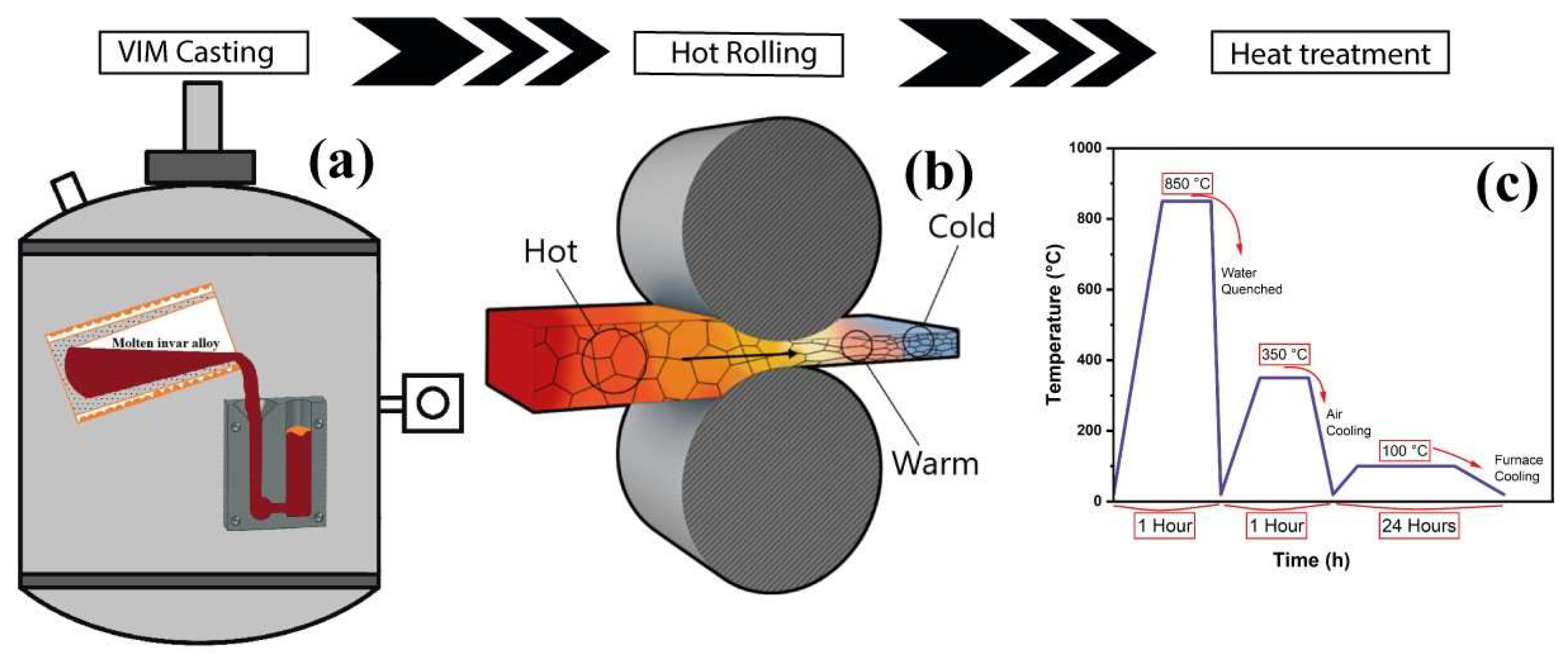
Figure 1. The production processes of samples; (a) casting process by VIM, (b) warm rolling adopted from [21] and (c) heat treatment diagram.
Preprints 120945 g001
Figure 2. Normalized XRD patterns of the invar samples in various states.
Preprints 120945 g002
Figure 3. The optical microstructures images of the a) as-cast (AC), b) warm rolled at 900 °C (ACWT), c) quenched from 850 °C and tempered at 350 °C for 1-hour (ACQT) and d) aged at 100 °C for 24 hours (ACA).
Preprints 120945 g003
Figure 5. The SEM images of the a) as-cast (AC), b) warm rolled at 900 °C (ACWT), c) quenched from 850 °C and tempered at 350 °C for 1-hour (ACQT) and d) aged at 100 °C for 24 hours (ACA).
Preprints 120945 g005
Figure 7. CTE results of the as-cast (AC), warm rolled at 900 °C (ACWT), quenched from 850 °C and tempered at 350 °C for 1-hour (ACQT) and aged at 100 °C for 24 hours (ACA) samples.
Preprints 120945 g007
Figure 8. (a) Stress – Strain curves of the samples and (b) The UTS, total elongation, hardness (HV5) and average grain size results of the samples under different conditions.
Preprints 120945 g008
Figure 9. The magnetization versus magnetic field hysteresis loop was measured at room temperature for the different condition invar 36 samples.
Preprints 120945 g009
Table 1. Chemical composition and codes of the samples (all values in wt.%).
Chemical Composition
Alloying elements Fe Ni Mn Si Cr Cu Co C
Amounts 63.28 36.22 0.17 0.11 0.07 0.05 0.06 0.04
Sample Codes
AC As-cast in VIM
ACWR Warm rolled at 900 °C
ACQT Quenched from 850 °C and tempered at 350 °C for 1 hour
ACA Aged at 100 °C for 24 hours
Table 2. The variation in relative intensity of the five strongest XRD peaks.
Strongest Peak (111) (200) (220) (311) (222)
AC 100 20.38 24.37 15.10 7.24
ACWR 100 35.52 15.90 17.62 6.39
ACQT 100 42.05 40.56 27.44 8.37
ACA 100 35.18 37.82 20.79 5.27
Table 3. A comparison of the CTE values obtained in this study with those reported in the literature.
Condition 20–50 °C 20–100 °C 20–150 °C 20–200 °C 20–250 °C Reference
Water quenching after holding at 850 °C for 1 h, followed by tempering at 350 °C for 1 h and finally kept at 100 °C for 24 hours. 0.511 0.549 0.581 1.095 1.648 This study
Water quenching after holding at 840 °C for 1 h, followed by tempering at 315 °C for 1 h. 1.400 2.430 [52]
Water quenching after holding at 840 °C for 1 h, followed by tempering at 315 °C for 1 h. 1.400 2.420 [53]
Water quenching after holding at 840 °C for 1 h, followed by tempering at 315 °C for 1 h. 0.915 2.750 [54]
Water quenching after holding at 843 °C for 1 h, followed by tempering at 315 °C for 1 h and finally kept at 93 °C for 24 hours. 0.800 1.500 2.300 4.000 [35]
Disclaimer/Publisher’s Note: The statements, opinions and data contained in all publications are solely those of the individual author(s) and contributor(s) and not of MDPI and/or the editor(s). MDPI and/or the editor(s) disclaim responsibility for any injury to people or property resulting from any ideas, methods, instructions or products referred to in the content.
Copyright: This open access article is published under a Creative Commons CC BY 4.0 license, which permit the free download, distribution, and reuse, provided that the author and preprint are cited in any reuse.
Alerts
Prerpints.org logo

Preprints.org is a free preprint server supported by MDPI in Basel, Switzerland.

Subscribe

© 2025 MDPI (Basel, Switzerland) unless otherwise stated