1. Introduction
The Bridge Influence Line (IL) is an intrinsic characteristic of a bridge, illustrating the variations in parameters at specific points when a moving unit load is imposed on the bridge structure. Currently, bridge IL is widely used in various fields, such as bridge condition evaluation [
1,
2], model update [
3] and bridge weight-in-motion system [
4]. Accurate identification of the bridge IL holds paramount importance in these applications.
In past research endeavors, researchers have employed various methodologies to acquire bridge IL. For instance, towards the end of the last century, McNulty [
5] devised a "point-to-point" graphical method for rough estimation of bridge IL. Subsequently, Gonzalez and O'Brien [
6] proposed a method of estimating IL through partial derivatives, which, however, is prone to error accumulation and exhibits poor robustness in estimating IL at bridge boundaries. With technological advancements, a common approach for measuring IL involves identifying bridge IL from the response signals induced by a detection vehicle with calibrated axle load and spacing information as it traverses the bridge. O'Brien [
7] initially established a linear model for IL identification, treating the IL identification as an inverse problem using the least squares method. Nevertheless, the least squares method is sensitive to measurement noise. Hence, regularization methods are introduced to [
8,
9,
10] enhance the stability and accuracy of inverse problems by introducing penalty terms or other prior knowledge. For example, Chen et al. [
11] proposed a Tikhonov regularization model for identifying bridge IL. To accommodate IL of various shapes, Chen et al. [
8] also introduced a method combining sparse regularization and adaptive B-spline basis functions. Additionally, to address dynamic component in bridge responses induced by high-speed vehicles, Zheng et al. [
9] introduced a regularization-based least squares QR decomposition model. While regularization methods can enhance the stability of inverse problems, their computational efficiency may be impacted. Therefore, frequency domain methods [
12,
13] are applied to improve computational efficiency. What’s more, various methodologies and technologies [
14,
15,
16,
17] are employed to acquire bridge IL to aid in the assessment of bridge condition and structural performance.
Following years of iterative refinement, the methodologies for IL identification have witnessed substantial advancements in accuracy, robustness, and applicability. Nonetheless, there remain two pressing challenges that demand resolution:
The inadequate accuracy and efficiency of deflection response measurement of concrete bridge with non-contact scheme. The inherent characteristics of concrete bridges, characterized by small span and high stiffness, lead to minimal deflection deformations under vehicular loads. However, the limited ability of visual technology to capture subtle structural deformations poses a challenge, thereby constraining the application of non-contact measurement schemes in concrete bridge. Although researchers [
18,
19] have already leveraged computer vision technology to achieve non-contact measurement of bridge response signals, the presence of irrelevant information in the vicinity of the focal point can lead to a sharp increase in data volume. Therefore, there is an urgent need for a non-contact bridge response measurement technology that can be applied in diverse and complex scenarios.
The ill-conditioned nature of the inverse problem in IL identification. Traditional IL identification methods involve constructing matrices based on load information and then inversely inferring IL from response signals, representing a typical class of inverse problems. While regularization methods mitigate the ill-conditioning effects of inverse problems to some extent by introducing penalty functions, they do not fundamentally eliminate these effects. Furthermore, after discussing the impact of vehicle axle spacing on the accuracy of IL identification results, Chen et al. [
20] equivalently transformed vehicle loads into unit forces to circumvent the ill-conditioning of the inverse problem. However, this approach somewhat restricts the applicability of the method. Therefore, there is an urgent need for an IL identification model based on existing time-domain signal inference to expand the application scenarios of IL identification technology.
In recent years, non-contact dynamic displacement monitoring instruments and methods have experienced rapid development, including global positioning system [
21,
22], interferometric radar system [
23,
24], and computer vision system [
18,
19]. Among these, computer vision involves using machines to replace human eyes for measurement or judgment, fostering analytical and adaptive capabilities to environmental changes. In terms of instrument cost, installation effort, and measurement capabilities, computer vision systems offer advantages over traditional displacement sensors in frequency range and spatial resolution [
25]. For example, the use of template matching [
26,
27] involves installing templates under the bridge deck to measure the motion changes at a specific point on the bridge deck when pedestrians or vehicles pass by. Additionally, feature matching methods [
28,
29] avoid pasting targets on the structure's surface to calculate structural displacements. However, template matching methods require the installation of templates at the measurement site, which may not be suitable for some engineering projects and can only extract deflection displacements at the template installation location [
30]. Feature matching methods require the presence of distinctive points in the structure for detection and tracking, typically points with significant differences in surrounding pixel values, such as line segment intersections [
31], whose accuracy depend on the capabilities of feature point detection and matching algorithms. Therefore, the Lucas-Kanade (LK) optical flow method [
32,
33] is introduced. As a classic motion tracking algorithm, it is simple, practical, and stable, and does not require the placement of targets or markers on the structure, significantly expanding the application scenarios of the algorithm. By modifying the feature point detection method in the algorithm, any point can be manually selected as a feature point for the optical flow algorithm. Nevertheless, the clarity of feature points within the camera's field of view may be insufficient, and there could be instances of missing video frames, leading to a significant impact on the accuracy of subsequent optical flow algorithms [
34]. This can make it challenging to effectively extract genuine structural displacement information, particularly for measuring small deflections in concrete bridges. Hence, edge detection [
35] technology is used to enhance the robustness of measurements. This technology eliminates irrelevant information in the image, such as bridge surface textures and cracks, retaining only the essential structural attributes, which can significantly reduce data volume. At the same time, extracting IL from structural response requires overcoming the ill-conditioning of inverse problems. However, researches predominantly employ regularization techniques to suppress the ill-conditioned nature of inverse problems. There is no effective IL identification model that can consider the effects of multi-axle loads to mitigate ill-conditioning issues.
To address the aforementioned issues, this study proposes a computer vision aided deflection IL identification method enhanced by edge detection and time-domain forward inference (TDFI). This method utilizes the LK optical flow method in computer vision technology to achieve non-contact measurement of bridge response. By employing edge detection to create virtual tracking points at the bridge edges, the LK optical flow method is used as a motion tracking technique to capture the movement of these virtual tracking points, thereby obtaining the dynamic deflection response of the bridge at any cross-section. This approach overcomes environmental factors such as lighting interference and expands the application scope of computer vision technology. To mitigate the ill-posed nature of the inverse problem, this study introduces a new IL identification model with TDFI. This model recursively obtains the static response information generated by the bridge under the action of preceding axles on multi-axle vehicles, and then calculates the IL by dividing the response by the preceding axle weight. Additionally, a reduction coefficient for axle weight ratios is proposed to address the amplification of certain noise, ensuring that the preceding axle weight is greater than any other axle, thereby increasing the weight of the preceding axle and reducing the axle weight ratio. Finally, this method is applied to numerical examples of a simply supported concrete beam, indoor experiments of a simply supported beam, and field tests of a three-span continuous concrete beam bridge. The case studies demonstrate that this method can accurately and effectively measure the dynamic deflection response of concrete bridges. The TDFI model and axle weight ratio reduction coefficient can effectively avoid the ill-posed nature of the inverse problem and accurately identify deflection IL.
The primary contributions of this study can be succinctly delineated as follows:
Traditional LK optical flow methodologies are constrained by hardware limitations, resulting in a lack of clarity in feature points within the camera's field of view and occasional loss of points in certain video frames. This impediment hampers the effective measurement of concrete bridge deflection. To address this challenge, this research introduces an edge detection technique that discerns boundaries by identifying maximum values in the first-order derivatives of the image. By selectively eliminating extraneous information in the image that is unrelated to the focal points, only pertinent structural attributes are retained to bolster the resilience of deflection measurements.
Conventional methods for IL identification necessitate the construction of matrices predicated on load data, followed by the inverse reconstruction of IL from response signals, constituting a quintessential inverse problem. To surmount the ill-conditioned nature of the inverse problem, this study propounds a new IL identification model with TDFI. This model iteratively acquires response data engendered by the bridge under the sequential influence of axles on multi-axle vehicles, computes the IL by normalizing the response by the weight of the preceding axle, and introduces a reduction coefficient for axle weight ratios to mitigate noise amplification, thereby facilitating precise IL identification.
The deflection IL identification methodology advanced in this investigation leverages computer vision technology to transcend conventional contact-based measurement paradigms, markedly enhancing the operational efficiency and applicability of IL identification techniques in concrete bridge.
2. Elaboration of the Proposed Deflection IL Identification Method
This section intricately elucidates the theoretical underpinnings of the proposed deflection IL identification method in this manuscript. It is structured into two main segments: the dynamic deflection response measurement of concrete bridge and the IL identification. The initial segment encompasses a comprehensive review of the foundational principles of LK optical flow methods, followed by an exposition on the refinement of the LK optical flow technique through the integration of edge detection mechanisms. Subsequently, a succinct synthesis of the procedural steps involved in capturing dynamic deflection responses is provided. Moving on to the second segment, a rigorous derivation of the mathematical model of TDFI for IL identification is presented, alongside the proposition of axle weight ratio reduction coefficient tailored to attenuate the deleterious effects of noise. The concluding part of this section encapsulates a holistic summary of the computational vision aided deflection IL identification approach.
2.1. Dynamic Bridge Deflection Response Measurement with Edge Detection
To overcome the limitations of contact-based measurement in identifying IL for bridge response, this section uses LK optical flow method theory to measure structural dynamic deflection, with edge detection to enhance the deflection measurement robustness of concrete bridge.
2.1.1. Recap of LK Optical Flow Method Theory
The concept of optical flow [
36] was initially proposed in 1950, defining the instantaneous velocity of pixel motion in a two-dimensional image sequence as optical flow, indicating the spatial movement of objects. Bruce D. Lucas and Takeo Kanade [
32] introduced the LK algorithm in 1981, aiming to compute dense optical flow. However, this method is prone to being applied to a subset of points in the input image, making it a crucial technique for sparse optical flow algorithms. The LK algorithm can be utilized in sparse scenarios with specific tracking points as it relies solely on local information derived from small windows around an interest point. Recognized as a classical algorithm, the LK optical flow method is esteemed for its stable tracking, low computational burden, and real-time performance. Nonetheless, successful tracking using this method necessitates distinct features in the target objects. These feature points come from the structure's surface, move with the structure in the real world, and the structure's vibration is recorded in two-dimensional images by the camera. The LK optical flow method picks up the feature points captured in the image to calculate their motion in the two-dimensional plane. Through camera calibration, the motion of the structure in the image can be converted into real-world motion.
The fundamental assumptions of the optical flow method are that the brightness of the same object remains constant across different frames and the motion distance of the object between adjacent frames is relatively small [
37]. The following theoretical formulas will be used to explain these two assumptions. An arbitrary feature point
is denoted in the next frame image as
. Based on the assumption of constant brightness, the following equation can be derived:
Assuming
and
as the velocity vectors of optical flow along the two-dimensional coordinate axes, and considering
,
and
as the partial derivatives of the corresponding pixel points in the image, the fundamental optical flow constraint equation can be established:
In the process of solving, additional constraints are required to accurately determine
and
. The LK optical flow method introduces the condition that the optical flow within the neighborhood of a target pixel is consistent, implying that neighboring pixels in the same scene exhibit uniform velocities. Assuming a window
of size
containing these pixels, a system of equations can be formulated based on the fundamental optical flow constraint, represented in matrix form as:
After establishing the optimization conditions mentioned above, the system of equations can be solved using the method of least squares:
where
,
. Then, the optical flow vector
of the target point can be calculated. The pixel displacements of the virtual tracking points obtained through the LK optical flow method can be used to estimate the structural displacements from the captured video images. To establish the relationship between pixel coordinates and world coordinates, the simplest and most convenient camera calibration method is the scale factor method:
where
is a full projection matrix and
is an arbitrary coefficient of
. This method allows for the rapid establishment of the relationship between the two coordinate systems, enabling the conversion of pixel displacements
into actual structural displacements
.
Traditional LK optical flow methodologies are constrained by hardware limitations, resulting in a lack of clarity in feature points within the camera's field of view and occasional loss of points in certain video frames. This impediment hampers the effective measurement of genuine structural displacement information, especially for the measurement of small structure deformation. Therefore, in the next section, this study will establish virtual tracking points through edge detection to elucidate the optical flow paths of structural motion.
2.1.2. Virtual Tracking Points Establishment Using Edge Detection
Utilizing edge detection [
38,
39], the virtual tracking points at the peripheries of bridges established by image processing represents an innovative methodology that enables the creation of virtual points on the structural surface to monitor displacements and deformations. The primary advantage of this approach lies in its capacity to generate virtual tracking points at arbitrary cross-sections of the structure and employ the LK optical flow algorithm to capture the motion of these points, thereby elucidating the dynamic response of the structure across various cross-sections. This technology particularly addresses the challenge of accurately measuring small deflections in concrete bridge.
Commencing with an exploration of the theoretical underpinnings of edge detection, these techniques serve the primary purpose of filtering out extraneous information in images, such as surface textures and cracks on bridges. By selectively preserving essential structural attributes and discarding non-essential details during image processing, edge detection significantly reduces data volume. This reduction is facilitated by the inherent color disparities between the bridge and its background, which manifest as distinct margins at the edges of the bridge. Through the identification of points exhibiting grayscale variations in the image, edge detection effectively retains critical structural information while eliminating natural texture elements, thereby mitigating the impact of noise. Commonly employed edge detection operators include the Canny operator [
40,
41], and Sobel operator [
41,
42], etc.. Among these, the Sobel operator stands out for its integration of Gaussian smoothing and differential operations, endowing it with robust noise resistance and algorithmic simplicity, thus enhancing its efficiency in practical applications. The operational principle of the Sobel operator in edge detection entails the identification of maximum values in the first-order derivative of the image to detect edges, followed by the estimation of local edge directions based on the computed results, typically derived from gradient directions. The Sobel operator is characterized by two sets of matrices:
In the aforementioned formulas,
and
represent edge operators along two pixel coordinate directions, while
denotes the image undergoing edge detection. For
Figure 1(a), a 3x3 matrix is applied to the image data and the corresponding operator values through plane convolution, yielding gradient values
and
in the x and y directions, respectively.
is utilized for detecting vertical edges, while
is employed for detecting horizontal edges. The approximate values of horizontal and vertical gradients for each pixel in the image can be calculated using Equation (6-5). When reaching the maximum value, it is considered an edge, followed by the calculation of the gradient direction using Equation (6-6).
Figure 1(b) illustrates the beam edge after undergoing edge detection. The results indicate that the use of edge detection techniques can significantly capture the edge features of the beam.
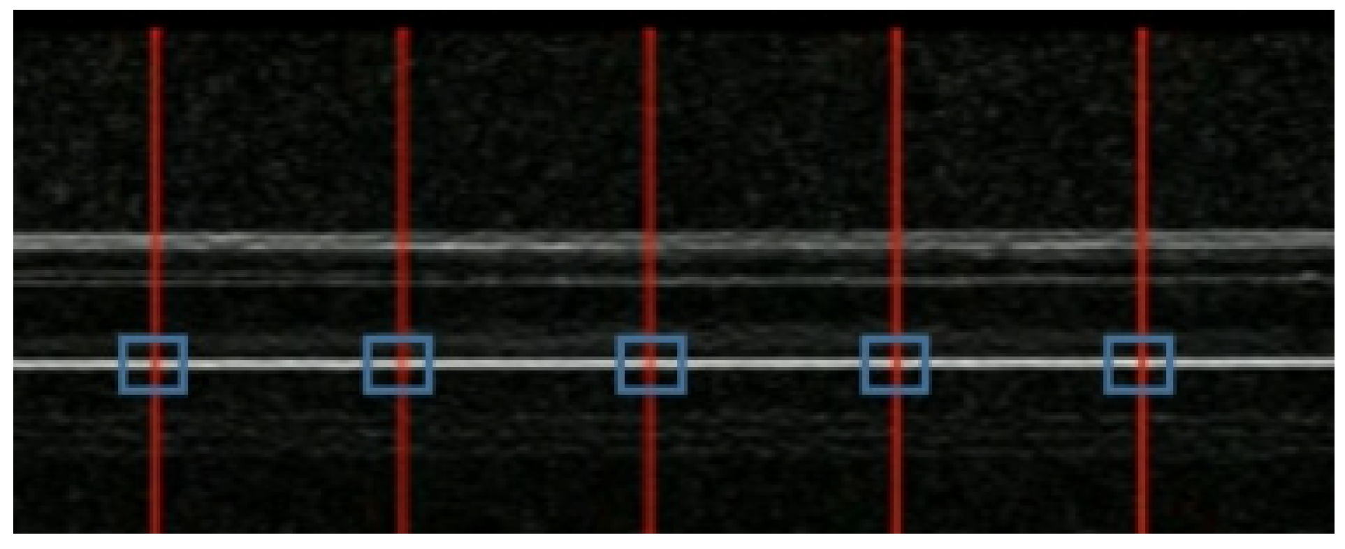
Next, the establishment of virtual tracking points will be discussed based on the Sobel edge operator. One of the underlying assumptions in optical flow tracking is the constancy of pixel values for corresponding points between consecutive frames. Edge detection serves to eliminate superfluous texture features, reduce noise interference, and preserve the smooth boundary information of the bridge. As illustrated in
Figure 2, the intersection points within the blue box serve as virtual tracking points. This methodology allows for the creation of virtual tracking points at arbitrary sections as required.
2.1.3. Steps of Dynamic Bridge Deflection Measurement
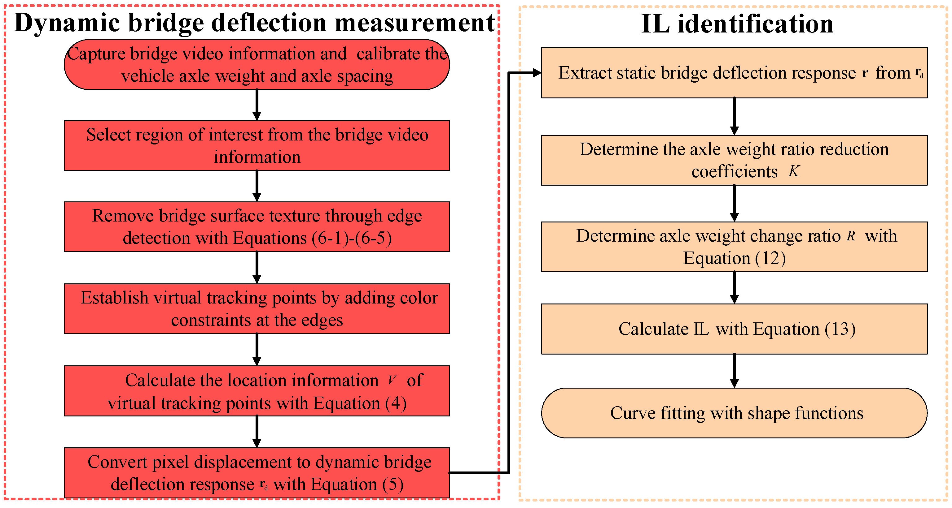
This section aims to enhance the robustness of the LK optical flow method for measuring the dynamic deflection response of bridges by establishing virtual tracking points using edge detection algorithms and image processing tools. The basic steps involved are as follows:
Capture bridge video information through cameras when vehicles pass over the bridge.
Select region of interest from the bridge video information.
Remove bridge surface texture through edge detection with Equations (6-1)-(6-6).
Establish virtual tracking points by adding color constraints at the edges.
Calculate the location information of virtual tracking points through the LK optical flow method with Equation (4).
Convert pixel displacement to dynamic deflection response through camera calibration with Equation (5).
2.2. Time-Domain Forward Inference for IL Identification
In order to mitigate the ill-conditioned nature of the inverse problem in IL identification, this section elucidates the process of bridge response formation in the time domain through a forward inference scheme. This methodology is employed to discern the IL, while concurrently introducing the concept of axle weight ratio reduction coefficient to mitigate the amplification of noise in the bridge response signal.
2.2.1. Mathematical Model of the TDFI
IL is a fundamental metric of the static properties of bridges. Before applying TDFI to compute IL, it is imperative to utilize advanced quasi-static component extraction techniques [
17,
21] to derive static deflection response
from dynamic deflection response
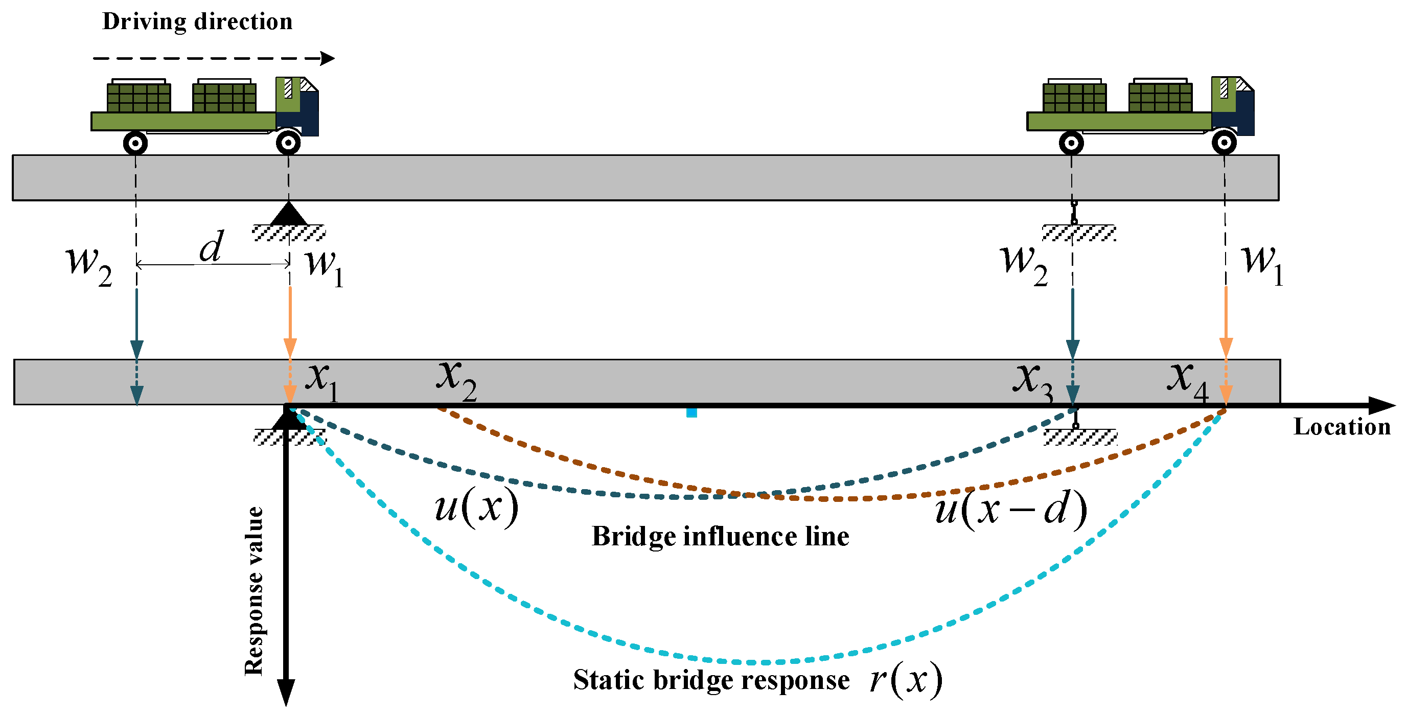
. To elaborate on the TDFI model in detail, this section considers the scenario of a two-axle heavy vehicle traversing a bridge, as depicted in
Figure 3. The figure illustrates the process of the two-axle vehicle crossing the bridge from the front axle to the rear axle departing from the bridge. In this scenario, the front axle weight is denoted as
, the rear axle weight as
, and the vehicle generates a static response signal
during its travel. Here,
represents the position information of the front axle while traversing the bridge, with the starting position on the bridge denoted as
and the position when the rear axle departs from the bridge as
.
represents the length of the bridge, and
represents the distance between the two axles of the vehicle. The response information at a specific section of the bridge is equal to the sum of the product of each axle weight and the value of the unit IL at the corresponding position. The IL is an inherent property of the bridge. In this case, assuming that the IL function for the front axle is denoted as
, with the range of
from
to
, and the IL for the rear axle is denoted as
, with the range of
from
to
. Therefore, the static response
at a specific location is given by:
Taking into account the differences in the number and weight of axle acting on the bridge in different intervals, the Equation (7) can be rewritten as follows:
The equation above reveals the recursive relationship of the IL in the time domain. The at position is derived from the at position . This method of inferring the IL by recursively propagating in the time domain is called the TDFI model.
To extend the TDFI model to a multi-span bridge, Equation (7) can be rewritten as follows:
where,
represents the number of axle loads,
represents the distance between the
ith axle and the front axle with
, and
is weight of the
ith axle. Using the same approach as in Equation (9), the calculation formula for IL is as follows:
2.2.2. Noise Amplification Circumvention with Axle Weight Ratio Reduction Coefficient
The previous section derived the TDFI model for IL identification. However, the measured bridge response is a signal contaminated with noise, which can significantly affect the accuracy of IL identification. The presence of the noise term
in Equation (10) persists throughout the entire recursive process, and the axle weight ratio
has an impact on the IL identification results during the computation. When
is equal to or greater than 1, the noise gets amplified, causing the function to deviate from the true value. Conversely, when the
is less than 1, the noise gradually diminishes, leading to the convergence of the computed results around the true value. Hence, the influence of noise on the
calculation can be disregarded. To mitigate the phenomenon of noise amplification, this study introduces an axle weight ratio reduction coefficient
. The selection of its value is guided by the principle of ensuring
surpasses any other axle weight, thereby augmenting the weight of the preceding axle and reducing the axle load ratio. The function
represents the IL function after incorporating the axle weight ratio reduction coefficient
.
By introducing the axle weight ratio reduction coefficient
, the influence of noise can be effectively reduced, ensuring that the IL identification results converge to the exact values. However, due to the increase in the denominator, the introduced function
is scaled down compared to the exact IL function
as a whole. Therefore, it is necessary to restore the function
to its true values. According to the order of the vehicle axles on the bridge, the ratio
of the axle weight before and after reduction on the bridge is given by:
To restore the function, multiply each segment's axle weight change ratio
by the corresponding segmented function. This will allow for the restoration of the function.
In order to accentuate the smooth characteristics of the IL, this study employs a curve fitting approach with shape functions [
9,
11] to fit the final identification results.
2.3. Flowchart of the Proposed Method
There are two parts of the IL identification method proposed in this article, mainly including dynamic bridge deflection measurement and IL identification. The specific flowchart of the method is shown below.
Figure 4.
Flowchart of the proposed IL identification method.
Figure 4.
Flowchart of the proposed IL identification method.
3. Numerical Example
To validate the accuracy and robustness of the TDFI model proposed in this paper for IL identification, this section presents a numerical example of a simply supported concrete beam. Initially, a nominal case is employed to demonstrate the feasibility and precision of the method. Subsequently, its robustness is scrutinized through a parametric analysis.
3.1. Nominal Case
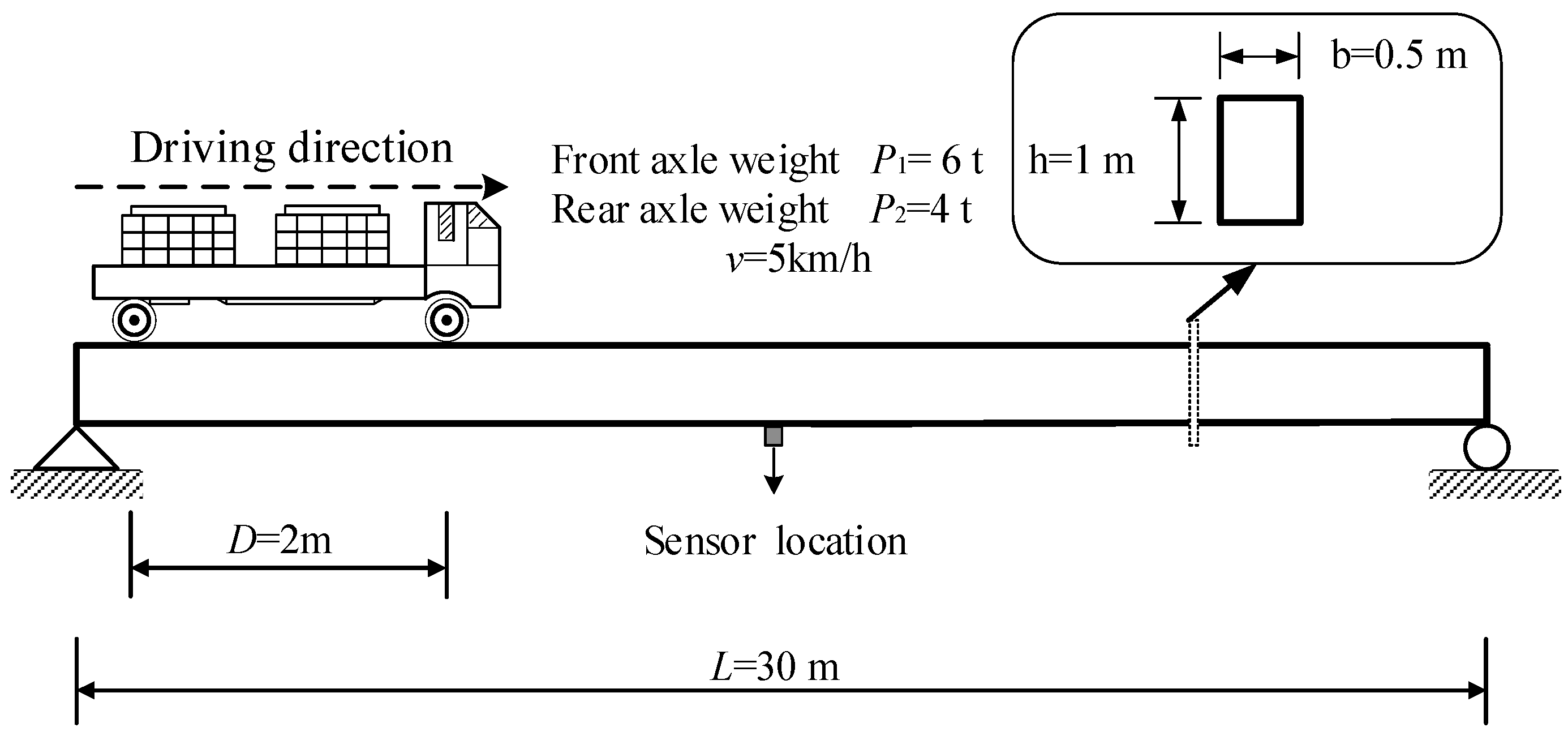
The numerical examples in this article are mainly used to validate the feasibility of the TDFI model, as the dynamic bridge deflection can be generated by a MATLAB program. As shown in
Figure 5, it has a span of L=30m and a rectangular cross-section of 1m×0.5m. The beam material properties include Young's modulus
and density
. Using MATLAB programming, a finite element model of the concrete beam is established by uniformly dividing it into 300 beam elements along the longitudinal direction, with each element having a length of 1m. The bridge deflection response signal as the vehicle travels from the front axle on the bridge to the rear axle off the bridge is added with Gaussian white noise at a signal-to-noise ratio (SNR) of 30dB.
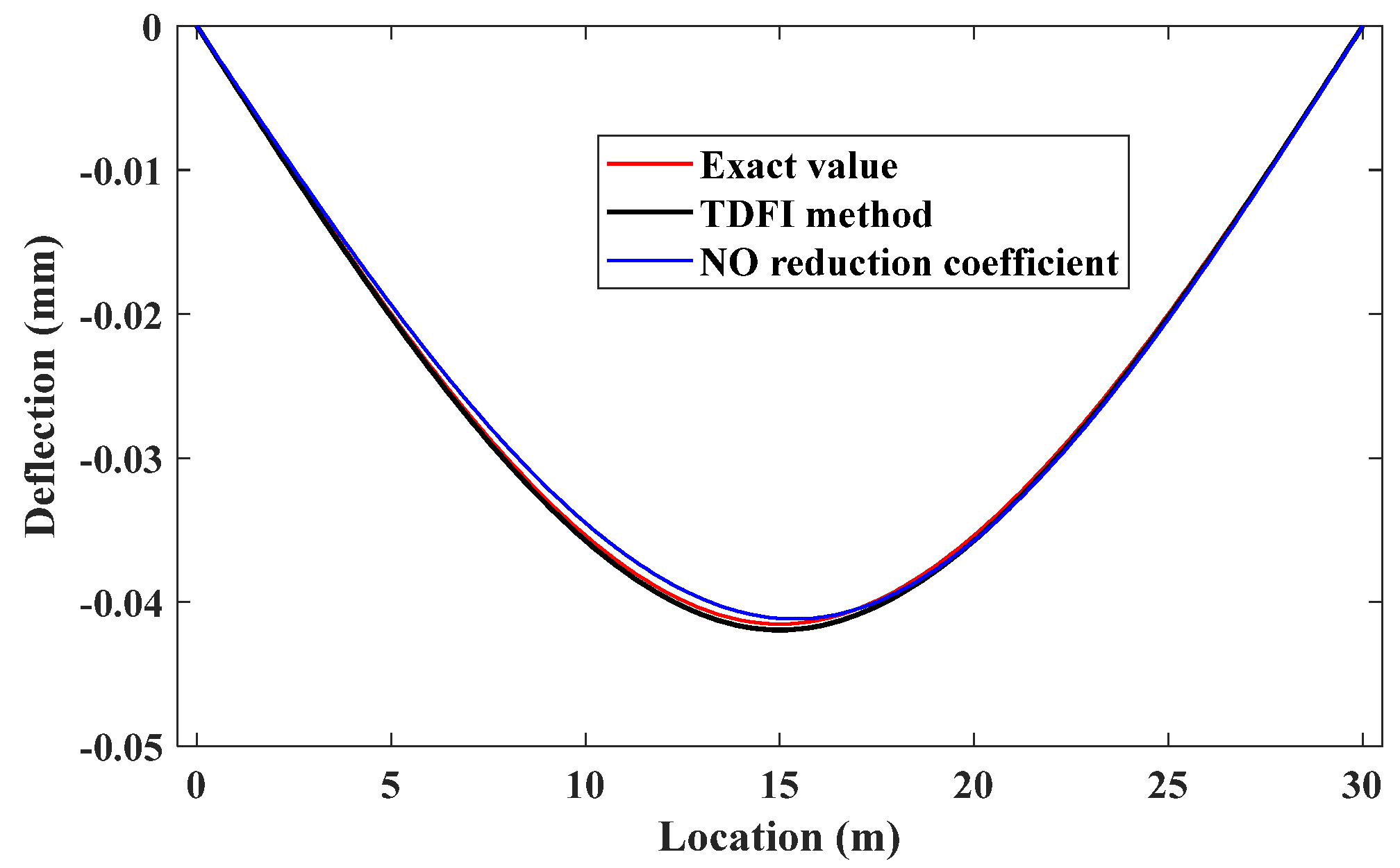
Using the proposed IL identification method to identify the IL, with a recursive step size of 1,
Figure 6 shows the calculation results. The red line represents the exact IL of the simply supported beam. The identification results obtained from TDFI are fitted using curve fitting tool of MATLAB. Additionally, the identification results without the introduction of the axle weight ratio reduction coefficient are also displayed in the figure. The results indicate that the method proposed in the paper achieves good consistency with the reference IL, especially with the application of the trimming coefficient significantly improving the accuracy of the identification results and overcoming the interference of noise.
3.2. Parametric Analysis
To verify the robustness of the method proposed in this study, this section mainly analyzes the impact of environmental noise and forward step size on the accuracy of identification results.
3.2.1. Effect of Noise Level
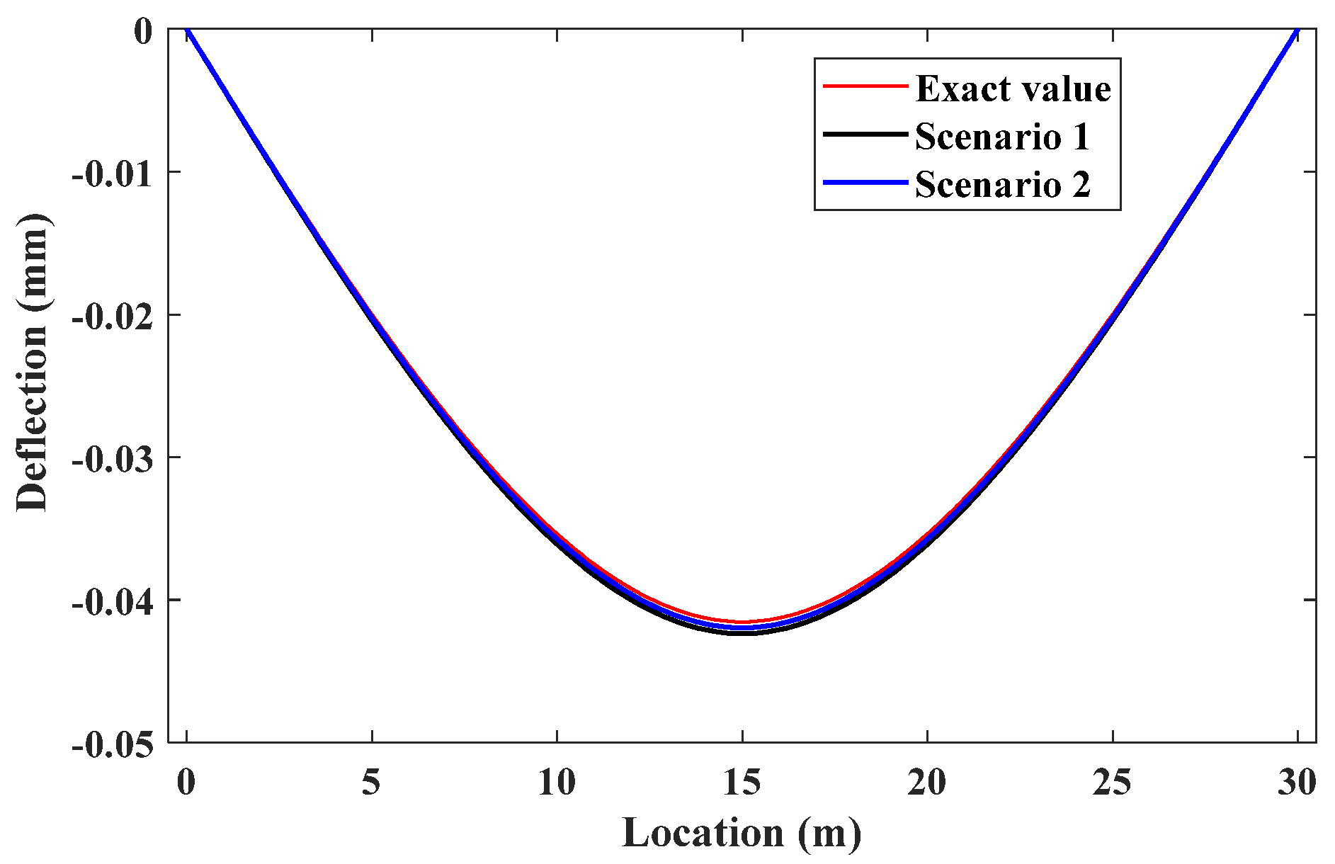
In the case of high SNR, the IL identification method proposed in the article can achieve good results. However, in most cases, due to interference from equipment or external factors, the obtained response often contains more noise. Moreover, as can be seen from the Equation (10), the results obtained in the initial stage will be used for subsequent iterations, making the identification performance in the initial stage crucial. In some cases, errors may occur when only the front axle of a vehicle is on the bridge, leading to greater noise. Therefore, two scenarios including the overall increase in noise and the increase in noise in the initial stage affecting the IL identification are considered.
In
Figure 7, the overall SNR of Scenario 1 is 20dB, and the SNR of Scenario 2 is 20dB in the initial stage and 30dB in the rest of the stages. The results show that even with an overall increase in noise, the IL identification results remain close to the baseline IL without significant fluctuations. When larger noise is applied in the initial stage, it does not have a major impact on the subsequent identification results, and the curve still converges near the baseline line. Therefore, this method demonstrates a certain level of robustness to noise.
3.2.2. Effect of Forward Step Size
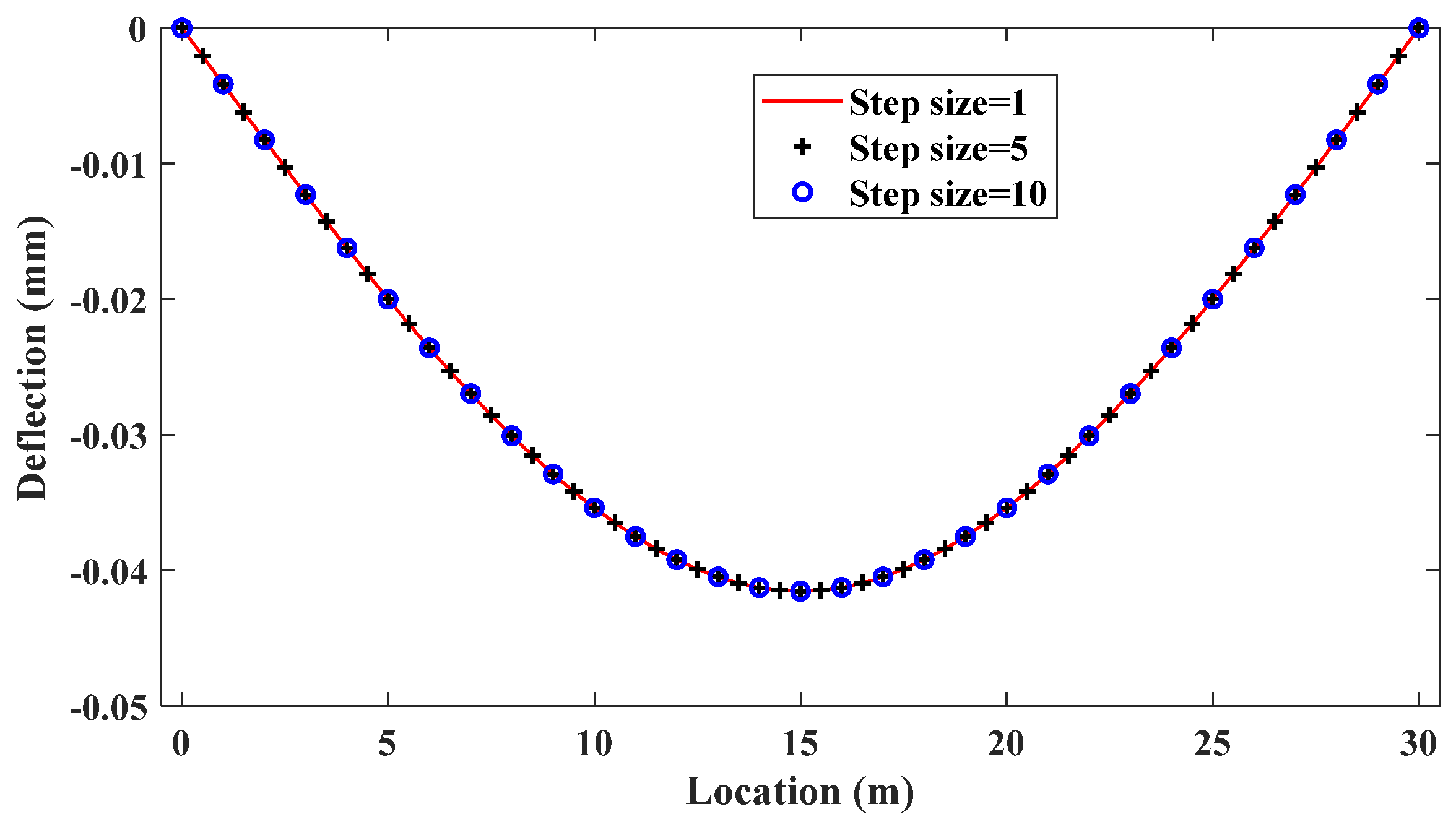
Considering the influence of each recursion step size on the outcomes, under normal circumstances, the impact line function progresses backward by one unit with each recursion step, and the maximum step size corresponds to the axle spacing. As depicted in
Figure 8, irrespective of whether Step=5 or Step=10, the derived points from the recursion align with the function curve at Step=1. Hence, varying the recursion step size does not compromise the precision of identification but does impact computational efficiency. Accordingly, the selection of the recursion step size can be tailored based on specific requirements.
4. Laboratory Validation
To validate the tracking performance of the proposed LK optical flow method in real-world scenarios, this study set up a simply supported beam indoors.
4.1. Case Overview
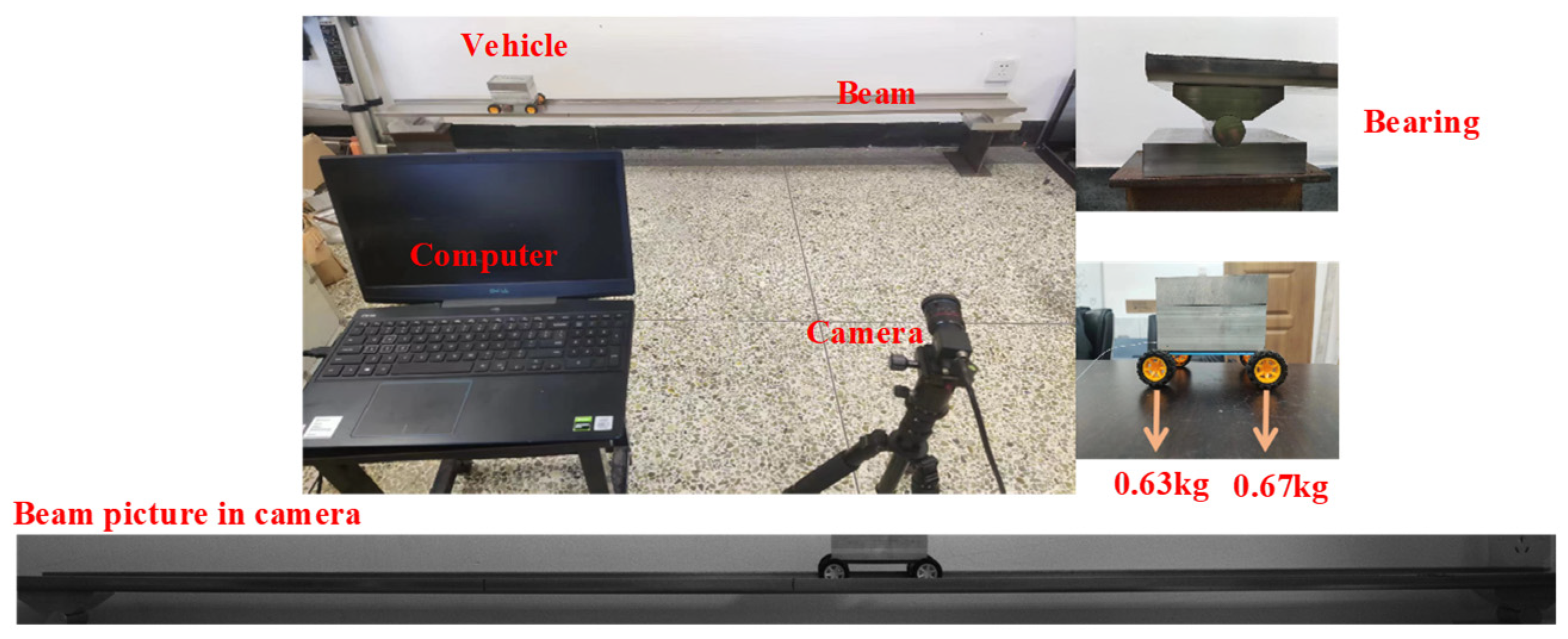
The beam with a length of 2m and a width of 13cm is shown in
Figure 9. A homemade model car is used to simulate a moving load, and a camera was placed 3m away from the simply supported beam to collect bridge deflection response. Additionally, an infrared sensor was installed at the mid-span of the beam to provide standard mid-span deflection signals. In the experiment, the model car moved uniformly under traction from one support to the other.
The industrial camera used in the experiment has a sampling frequency of 76 frames per second (76 FPS) and a pixel size of 2448×2048. To save storage space, a region of interest of 2400×150 pixels was selected from the camera's field of view. The video information completely captured the entire beam deformation process, including interferences such as the model car, background, and variations in lighting. An edge detection operator was used to filter the images, resulting in clear boundaries and the removal of unnecessary textures in the beam edge images. Subsequently, vertical grids were added to the beam edges using image processing tools, and the intersection points of the grids and edges were selected as tracking points for the optical flow algorithm.
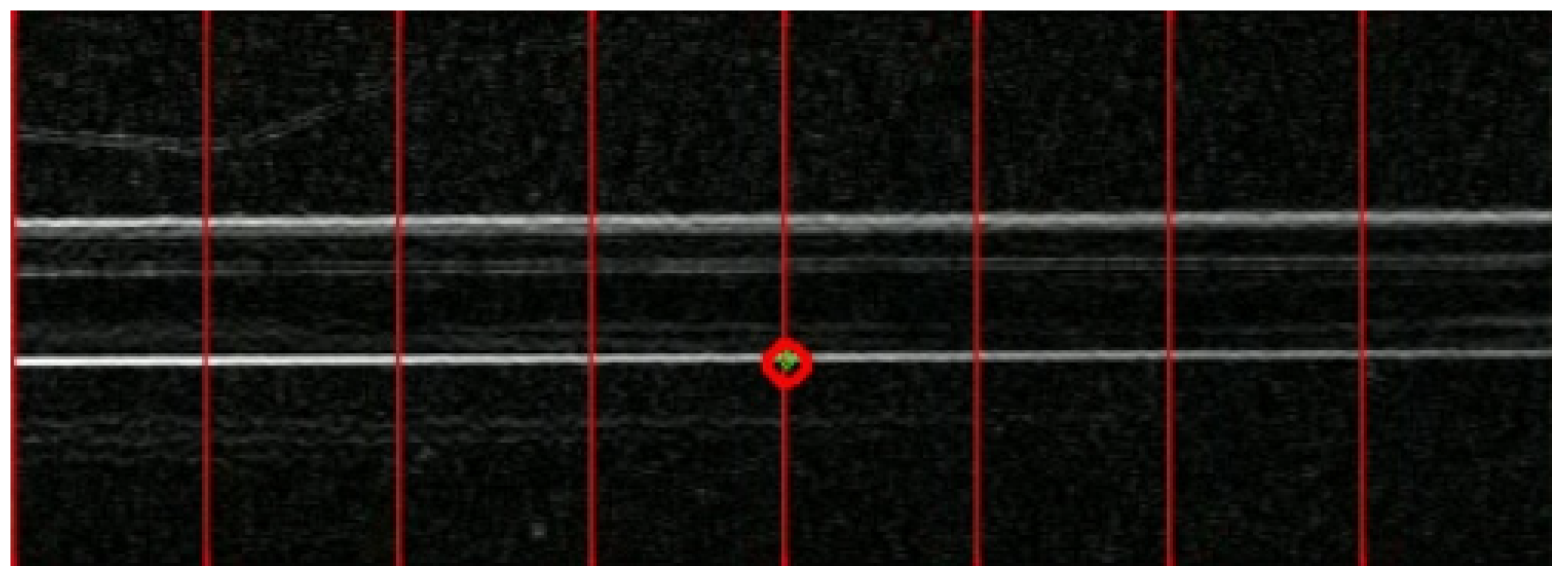
Figure 10 illustrates the process of the LK optical flow method tracking virtual points. The red circle represents the selected initial tracking point, while the green circle represents the real-time tracking point. Throughout the entire calculation process, the green circle remains within the red circle, demonstrating good robustness.
4.2. Measurement Analysis of the LK Optical Flow Method
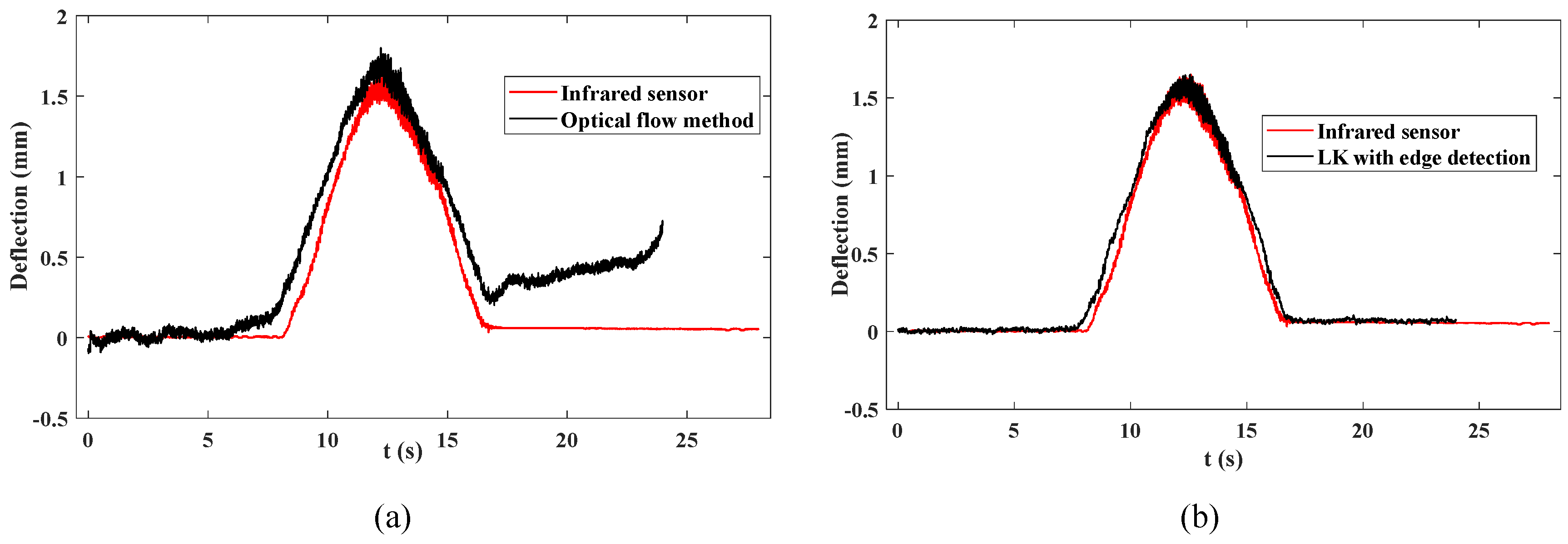
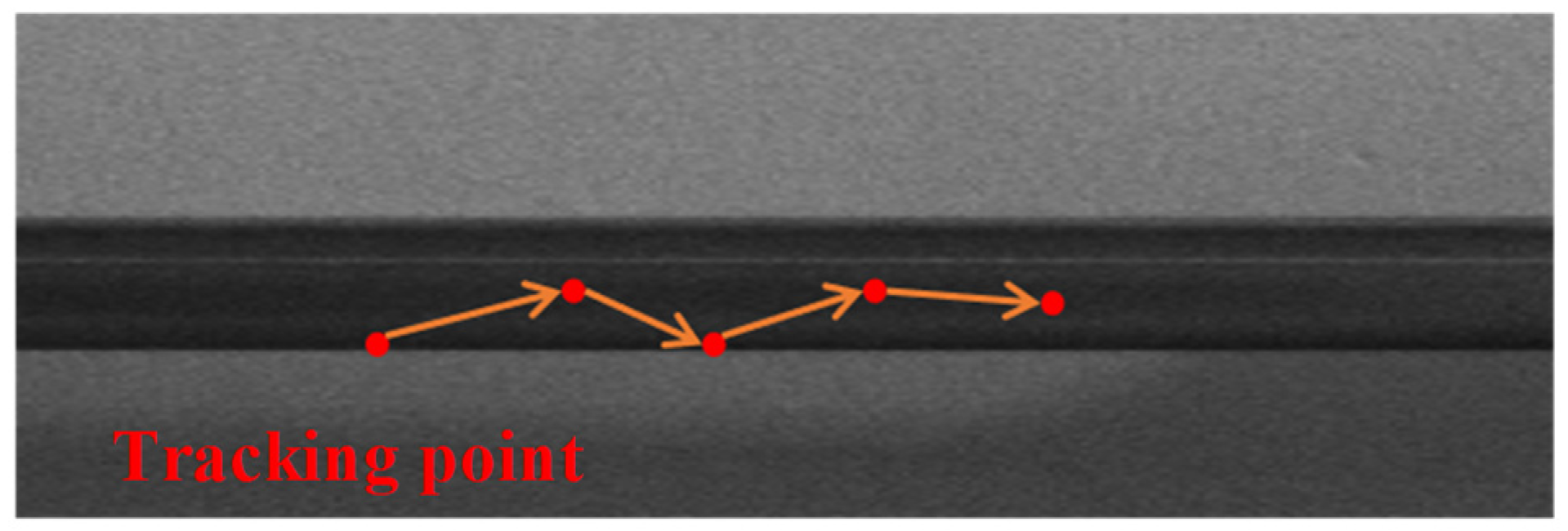
Figure 11(a) shows the deflection response extracted by the optical flow method in the original image compared to the deflection signals obtained by the infrared sensor. Due to the beam appearing as a gray area with width in the field of view, even though the initial tracking point is determined using a visual method, the brightness of this point is similar to the brightness of pixels in the adjacent area. Therefore, in subsequent calculations, this point will continuously slide and gradually deviate from the initial point, as shown in
Figure 11(b). Consequently, the black line in
Figure 11(a) will exhibit significant fluctuations, and the deflection curve will not return to its initial value. Using the virtual tracking points determined by edge detection instead of the initial points can effectively avoid the issues encountered in the experiment. As shown in
Figure 12, the results based on visual measurements and those obtained by the infrared sensor maintain good consistency throughout the entire curve. Error analysis was conducted between the deflection values obtained by the visual measurement method and those obtained by the infrared sensor in the two sets of Tests. The error in Test 2 is more stable and remains at a lower level, with the maximum error occurring at 12 seconds, with an error value of 6.57%. In contrast, the error curve in Test 1 deviates more from the accurate value and shows a trend of gradual expansion. In conclusion, the improved LK optical flow method using edge detection can accurately measure the dynamic deflection response of the bridge.
4.3. IL Identification with TDFI Model
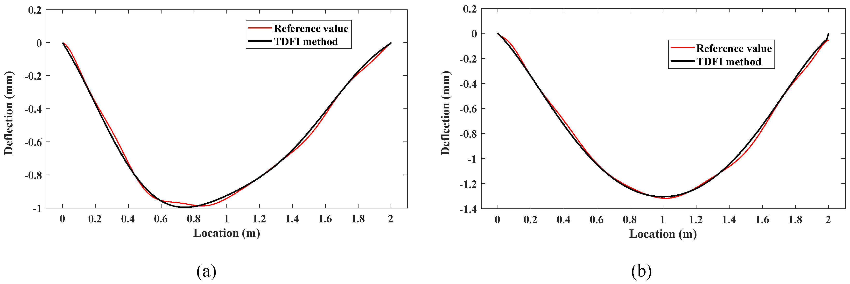
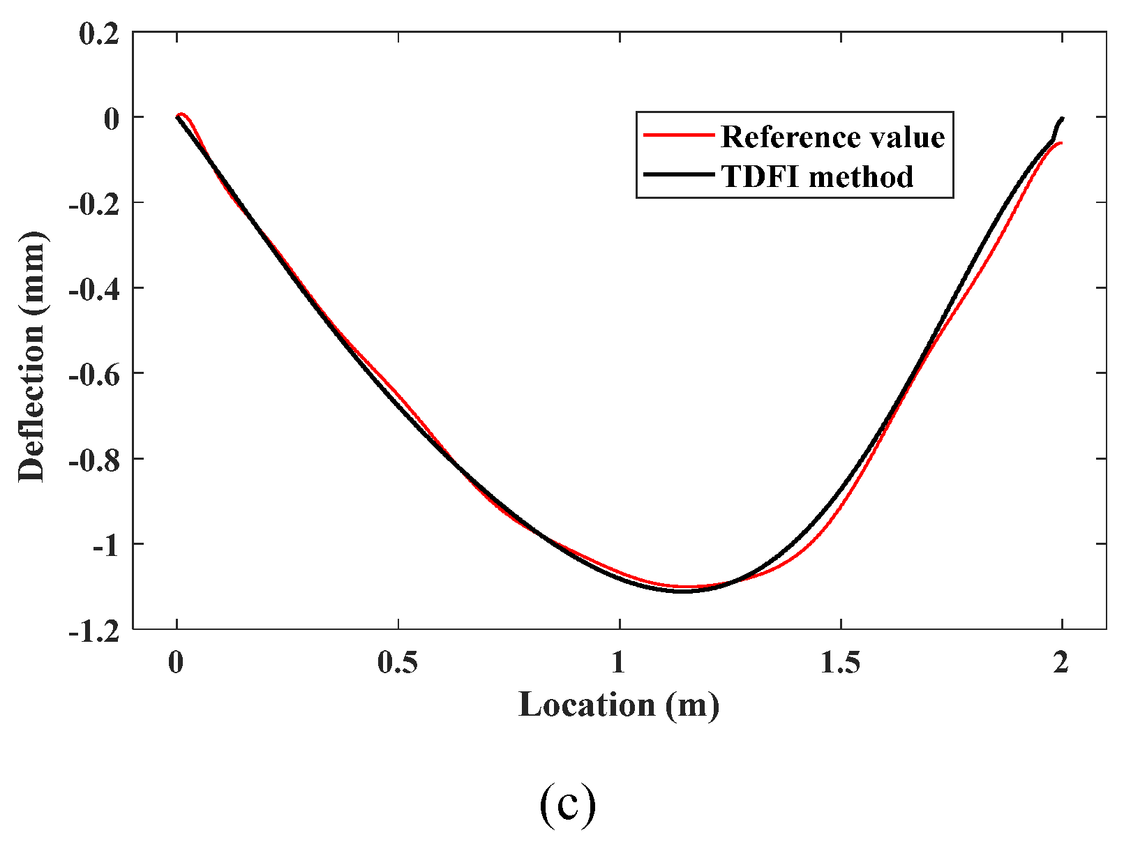
By combining the measured deflection response with the vehicle information, the ILs at 1/4 span, 1/2 span, and 3/4 span of the bridge are identified. In
Figure 13, the black curve represents the IL identified by the TDFI model, while the red curve represents the corresponding reference IL. Even in the presence of original noise, the identified ILs can fit well with the reference value. The TDFI method can overcome the ill-posed nature of the inverse problem, accurately identify the IL, and be applicable to practical situations.
5. Field Test
To further validate the accuracy and robustness of the proposed IL identification method, a field test experiment is conducted on a three-span prestressed concrete continuous box-girder bridge. The bridge's actual image is shown in
Figure 14. The layout schematic of the bridge is depicted in
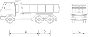
Figure 15, with spans of 28m+40m+28m. The measurement sections are chosen at the mid-span of the central span, with industrial camera to measure dynamic deflection, sampling frequency is 76 frames per second (76 FPS), pixel size is 2448×2048. To verify the accuracy of measuring bridge deflection using LK optical flow method, contacted deflection sensors are installed on the left and right sides of the bridge cross-section's centerline. For the field test, a type of three-axle truck is selected as the vehicle load, as shown in
Figure 16. The vehicle load information obtained from the WIM system is presented in
Table 1. Due to the relatively small distance between the rear two axles of the vehicle, these two axles can be considered equivalent to a single axle for calculation purposes.
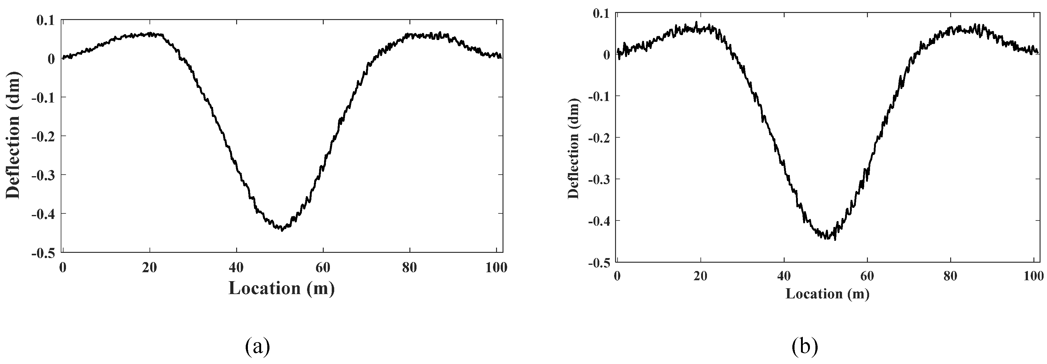
To obtain reference value of IL, during field test, the bridge is first loaded by a vehicle moving at a constant speed of 5 km/h across the bridge, and the bridge response signals are collected. The IL identified with the regularization method is used as the reference value. The bridge deflection responses obtained from contact measurement and LK optical flow method are shown in the
Figure 17. The results indicate that the LK optical flow method can provide measurements close to those obtained from contact-based measurement, significantly expanding the application scenarios of IL identification methods.
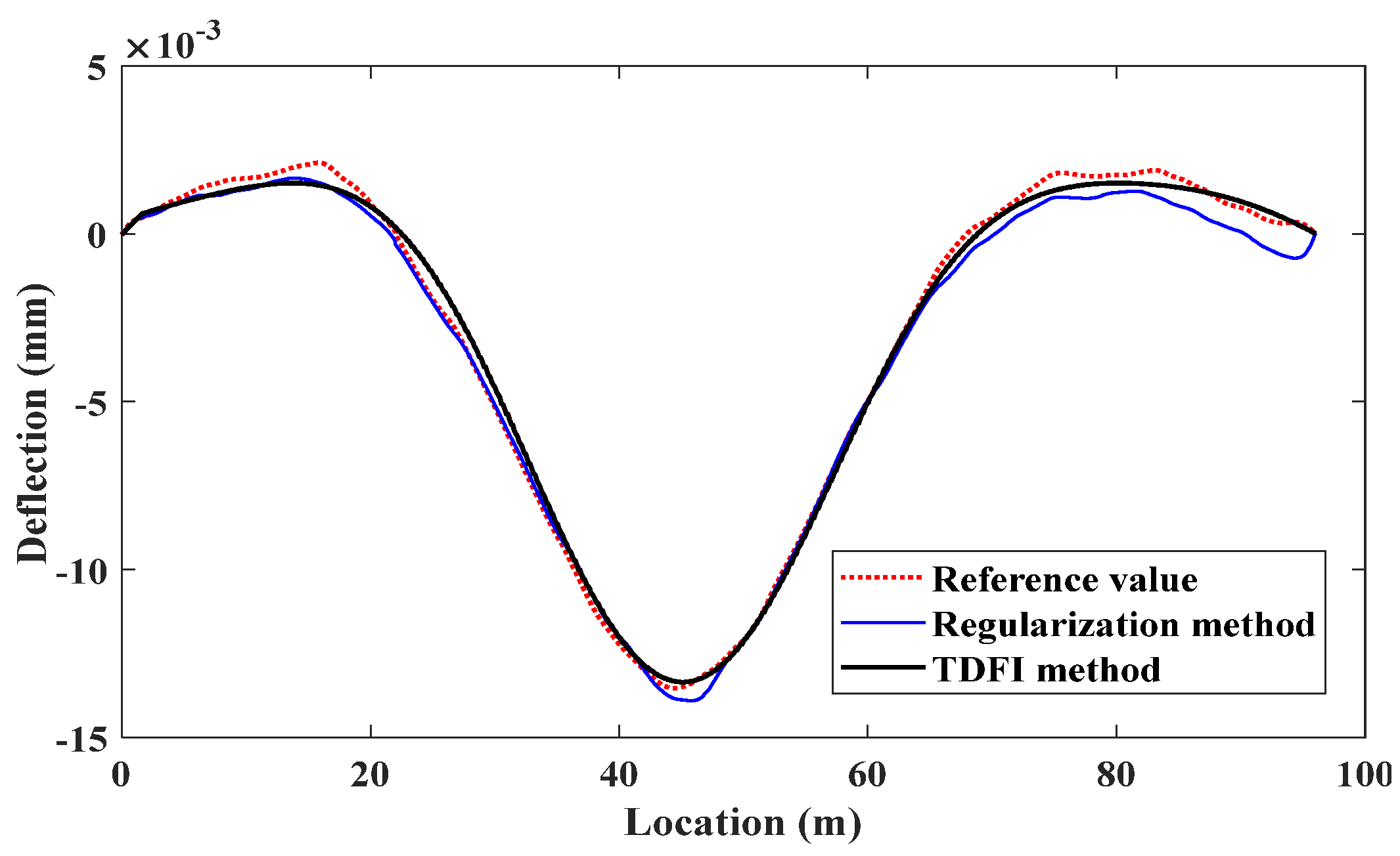
The deflection IL identification results using the TDFI method and regularization method are shown in the
Figure 18. Compared to traditional regularization method, the TDFI method can better suppress noise in the response by using the axle load trimming factor, while also avoiding the ill-posed nature of the inverse problem, leading to a better fit with the reference IL values. Hence, the proposed method can effectively measure the dynamic deflection response of concrete bridge and accurately identify IL.
6. Conclusions
This study proposes a computer vision aided deflection IL identification method enhanced by edge detection and TDFI. This method utilizes the LK optical flow method with edge detection to achieve non-contact measurement of concrete bridge responses. By employing edge detection identifying maximum values in the first-order derivatives of the image to create virtual tracking points at the edges of the bridge with image processing, the LK optical flow method is enhanced as a motion tracking technique to capture the movement of these virtual tracking points, thereby obtaining the dynamic bridge deflection response at any cross-section. To mitigate the ill-posed nature of the inverse problem, this study introduces a new IL identification model with TDFI. This model recursively obtains response information generated by the bridge under the action of preceding axles on multi-axle vehicles, and then calculates the IL by dividing the response by the preceding axle weight. Additionally, a reduction coefficient for axle weight ratios is proposed to address the amplification of certain noise, ensuring that the preceding axle weight is greater than any other axle, thereby increasing the weight of the preceding axle and reducing the axle weight ratio. Finally, case studies validate the performance of the proposed method. The main conclusions are summarized as follows:
This research introduces an edge detection technique that discerns boundaries to enhance the measurement robustness of LK optical flow method. The laboratory validation and field test validate the measurement accuracy of concrete bridge deflection.
This study propounds a new IL identification model with TDFI. The case studies validate that the model can mitigate the ill-posed nature of the inverse problem to accurately identify IL.
The deflection IL identification methodology advanced in this investigation leverages computer vision technology to transcend conventional contact-based measurement paradigms, markedly enhancing the operational efficiency and applicability of IL identification techniques in engineering contexts, especially in concrete bridges.
It is important to note that this method is based on optical video sensing technology and requires certain lighting conditions, which may limit its application at night. Future research will expand to include infrared sensor studies to overcome the limitations of non-contact measurement methods for nighttime use.
Author Contributions
Conceptualization, Jianfeng Chen and Long Zhao; methodology, Jianfeng Chen; software, Yuliang Feng; validation, Jianfeng Chen, Long Zhao and Yuliang Feng; formal analysis, Yuliang Feng; investigation, Jianfeng Chen; resources, Jianfeng Chen; data Long Zhao, Yuliang Feng; writing—original draft preparation, Jianfeng Chen; writing—review and editing, Long Zhao; visualization, Long Zhao; supervision, Long Zhao; project administration, Zhiwei Chen; funding acquisition, Zhiwei Chen. All authors have read and agreed to the published version of the manuscript.
Funding
The authors wish to acknowledge the financial support from the National Natural Science Foundation of China (NSFC-52278319).
Conflicts of Interest
The authors declare no conflicts of interest.
References
- Chen, Z.W.; Cai, Q.L.; Lei, Y.; Zhu, S. , Damage Detection of Long-span Bridges Using Stress Influence Lines Incorporating Control Charts, Science China Technological Sciences 57 (2014) 1689-1697. [CrossRef]
- Chen, Z.W.; Yang, W.B.; Li, J.; Cheng, Q.; Cai, Q.L. , A systematic method from influence line identification todamage detection: Application to RC bridges, Computers and Concrete 20 (2017) 563-572.
- Xiao, X.; Xu, Y.; Zhu, Q. , Multiscale Modeling and Model Updating of a Cable-Stayed Bridge. II: Model Updating Using Modal Frequencies and Influence Lines, Journal of Bridge Engineering 20 (2014) 04014113.
- Yan, W.J.; Hao, T.T.; Yuen, K.V.; Papadimitriou, C. , Monitoring gross vehicle weight with a probabilistic and influence line-free bridge weight-in-motion scheme based on a transmissibility-like index, Mechanical Systems and Signal Processing 177 (2022) 109133. [CrossRef]
- McNulty, P. , Testing of an Irish Bridge Weigh-in-Motion System, MEngSc thesis, University College Dublin (1999).
- González, A. ; E. O'Brien, Influence of dynamics on accuracy of a bridge weigh in motion system, Third International Conference on Weigh-in-Motion (ICWIM3) Iowa State University, Ames, 2002.
- Obrien, E.J.; Quilligan, M.J.; Karoumi, R. , Calculating an influence line from direct measurements, Proceedings of the Institution of Civil Engineers - Bridge Engineering 159(1) (2006) 31-34.
- Chen, Z.W.; Yang, W.B.; Li, J.; Yi, T.H.; Wu, J.; Wang, D. , Bridge influence line identification based on adaptive B-spline basis dictionary and sparse regularization, Structural Control and Health Monitoring 26 (2019) e2355. [CrossRef]
- Zheng, X.; Yang, D.H.; Yi, T.H.; Li, H.N.; Chen, Z.W. , Bridge Influence Line Identification Based on Regularized Least-Squares QR Decomposition Method, Journal of Bridge Engineering 24 (2019). [CrossRef]
- Chen, Z.W.; Zhao, L.; Yan, W.J.; Yuen, K.V.; Wu, C. , A statistical influence line identification method using Bayesian regularization and a polynomial interpolating function, Structural Control and Health Monitoring n/a e3080. [CrossRef]
- Chen, Z.W.; Cai, Q.L.; Li, J. , Stress Influence Line Identification of Long Suspension Bridges Installed with Structural Health Monitoring Systems, International Journal of Structural Stability and Dynamics 16 (2016) 1640023. [CrossRef]
- Hunt, V. , Nondestructive evaluation and health monitoring of highway bridges, 2000.
- Yan, W.J.; Yuen, K.V. , A new probabilistic frequency-domain approach for influence line extraction from static transmissibility measurements under unknown moving loads, Engineering Structures (2020). [CrossRef]
- Li, X.; Zhu, J. , Identification of bridge influence line and multiple-vehicle loads based on physics-informed neural networks, Structural Health Monitoring (2024) 14759217241248570. [CrossRef]
- Zheng, X.; Yang, D.H.; Yi, T.H.; Li, H.N. , Bridge influence line identification from structural dynamic responses induced by a high-speed vehicle, Structural Control and Health Monitoring 27 (2020). [CrossRef]
- Chen, Z.W.; Zhao, L.; Zhou, Y.G.; He, W.Y.; Ren, W.X. , Extraction of quasi-static component from vehicle-induced dynamic response using improved variational mode decomposition, Smart Structures and Systems 31(2) (2023).
- Ieng, S.S. , Bridge Influence Line Estimation for Bridge Weigh-in-Motion System, Journal of Computing in Civil Engineering 29(1) (2015) 06014006. [CrossRef]
- Zhou, Y.; Hu, J.N.; Hao, G.W.; Zhu, Z.R.; Zhang, J. , Identification of Influence Lines for Highway Bridges Using Bayesian Parametric Estimation Based on Computer Vision Measurements, Journal of Bridge Engineering 28(12) (2023) 04023087. [CrossRef]
- Zhou, Y.; Zhou, S.; Hao, G.; Zhang, J. , Bridge influence line identification based on big data and interval analysis with affine arithmetic, Measurement 183 (2021) 109807. [CrossRef]
- Chen, Z.W.; Guo, Z.C.; Ren, W.X.; Zhang, Y. , A novel bridge influence line identification approach based on nonlinear frequency modulation signal reconstruction, Mechanical Systems and Signal Processing 219 (2024) 111622. [CrossRef]
- Badran, A.; El-Geneidy, A.; Miranda-Moreno, L. , Intersection movements delay modelling based on crowd-sensed global positioning system trajectory data, Canadian Journal of Civil Engineering 51(9) (2024) 1056-1065. [CrossRef]
- Liu, H. , Acquisition method based on differential global positioning system for land resource data, Geotechnical Research (2024). [CrossRef]
- Sofi, M.; Lumantarna, E.; Zhong, A.; Mendis, P.A.; Duffield, C.; Barnes, R. , Determining dynamic characteristics of high rise buildings using interferometric radar system, Engineering Structures 164 (2018) 230-242. [CrossRef]
- Zhang, G.; Zhao, W.; Zhang, J. , Bridge distributed stiffness identification of continuous beam bridge based on microwave interferometric radar technology and rotation influence line, Measurement 220 (2023) 113353. [CrossRef]
- Shao, Y.; Li, L.; Li, J.; Li, Q.; An, S.; Hao, H. , Out-of-plane full-field vibration displacement measurement with monocular computer vision, Automation in Construction 165 (2024) 105507. [CrossRef]
- Gupta, A.; Sintorn, I.-M. , Efficient high-resolution template matching with vector quantized nearest neighbour fields, Pattern Recognition 151 (2024) 110386.
- Qureshi, A.M.; Mudawi, N.A.; Alonazi, M.; Chelloug, S.A.; Park, J. , Road Traffic Monitoring from Aerial Images Using Template Matching and Invariant Features, Computers, Materials and Continua 78(3) (2024) 3683-3701. [CrossRef]
- Zhang, X.; Wei, L.; Yao, L.; Zhong, J.; Wang, J. , Investigation of near-field jet stability of a single-hole injector based on fast X-ray phase contrast imaging and image feature matching, Experimental Thermal and Fluid Science 141 (2023) 110771. [CrossRef]
- Chu, Y.; Li, H.; Li, X.; Ding, Y.; Yang, X.; Ai, D.; Chen, X.; Wang, Y.; Yang, J. , Endoscopic image feature matching via motion consensus and global bilateral regression, Computer Methods and Programs in Biomedicine 190 (2020) 105370. [CrossRef]
- Bao, N.; Fan, Y.; Simeone, A.; Li, T.; Luo, Z. , Defect Detection System for Smartphone Front Camera Based on Improved Template Matching Algorithm, Procedia CIRP 103 (2021) 268-273. [CrossRef]
- Li, S.; Zhou, B.; Yang, B.; Ali, F.; Liang, Z. , Feature tracking and matching for wide-baseline images with closed-loop sequence, Computers and Electrical Engineering 110 (2023) 108871. [CrossRef]
- Lucas, B.D.; Kanade, T. , An Iterative Image Registration Technique with an Application to Stereo Vision, International Joint Conference on Artificial Intelligence, 1981.
- Liu, X.; Tang, J.; Shen, C.; Wang, C.; Zhao, D.; Guo, X.; Li, J.; Liu, J. , Brain-like position measurement method based on improved optical flow algorithm, ISA Transactions 143 (2023) 221-230. [CrossRef]
- Jodoin, P.M.; Mignotte, M. , Optical-flow based on an edge-avoidance procedure, Computer Vision and Image Understanding 113(4) (2009) 511-531.
- Yang, G.; Xu, F. , Research and analysis of Image edge detection algorithm Based on the MATLAB, Procedia Engineering 15 (2011) 1313-1318. [CrossRef]
- Arnheim, R.; Gibson, J.J. , The Perception of the Visual World, The Journal of Aesthetics and Art Criticism 11 (1952) 172.
- Alfarano, A.; Maiano, L.; Papa, L.; Amerini, I. , Estimating optical flow: A comprehensive review of the state of the art, Computer Vision and Image Understanding (2024) 104160. [CrossRef]
- Ma, P.; Yuan, H.; Chen, Y.; Chen, H.; Weng, G.; Liu, Y. , A Laplace operator-based active contour model with improved image edge detection performance, Digital Signal Processing 151 (2024) 104550. [CrossRef]
- Gao, P.; Song, Y.; Song, M.; Qian, P.; Su, Y. , Extract nanoporous gold ligaments from SEM images by combining fully convolutional network and Sobel operator edge detection algorithm, Scripta Materialia 213 (2022) 114627. [CrossRef]
- Zhang, X.; Zhang, Y.; Zheng, R. , Image edge detection method of combining wavelet lift with Canny operator, Procedia Engineering 15 (2011) 1335-1339. [CrossRef]
- Gaurav, K.; Ghanekar, U. , Image steganography based on Canny edge detection, dilation operator and hybrid coding, Journal of Information Security and Applications 41 (2018) 41-51.
- Ravivarma, G.; Gavaskar, K.; Malathi, D.; Asha, K.G.; Ashok, B.; Aarthi, S. , Implementation of Sobel operator based image edge detection on FPGA, Materials Today: Proceedings 45 (2021) 2401-2407. [CrossRef]
|
Disclaimer/Publisher’s Note: The statements, opinions and data contained in all publications are solely those of the individual author(s) and contributor(s) and not of MDPI and/or the editor(s). MDPI and/or the editor(s) disclaim responsibility for any injury to people or property resulting from any ideas, methods, instructions or products referred to in the content. |
© 2024 by the authors. Licensee MDPI, Basel, Switzerland. This article is an open access article distributed under the terms and conditions of the Creative Commons Attribution (CC BY) license (http://creativecommons.org/licenses/by/4.0/).
