1. Introduction
As the popularity of driver aid systems using radar technology reached its peak in recent years, the automotive industry stepped in, pushing demand for low-cost yet high-performance radar systems on a single integrated circuit even higher [
1,
2]. It is not surprising that traditional all-electric technology has reached its limits after a few decades of intense research and is now shifting more towards complex radiofrequency (RF) signal analysis using advanced digital modulation schemes to mitigate interference from co-existing systems in an already polluted RF spectrum [
3,
4,
5]. Any significant boost in performance of an analog design entails an even larger price tag since many additional components are required, particularly when coherent multi-band systems with high operational bandwidth are needed for an improvement in the range and resolution of radar detection [
6,
7,
8]. Searching for a solution to overcome the problems of an all-electric design, researchers saw an opportunity in the emerging opto-electronic field. It was previously demonstrated that microwave photonics is an excellent replacement for a RF signal generator in terms of phase noise and frequency scalability [
9]. Even more, a complete radar system can be built with the addition of optical modulators, beam splitters, photodiodes, lasers, and band-pass filters [
10,
11,
12,
13,
14,
15,
16]. Merging all building blocks into a single photonic integrated circuit (PIC) minimizes the complexity, cost, and power consumption of an entire radar system [
17,
18,
19,
20].
Microwave photonics technology opens the possibility of coherent signal generation in the optical as well as radio-frequency domain. Utilizing the silicon-on-insulator technique, a single core can be used to produce the required signals for radar as well as lidar detection systems [
7,
17,
21]. Frequency agile radar transceivers can be built, usually limited only by the bandwidth of the front-end design [
22]. As the optical comb generator can produce many harmonics (multiplication factor beyond 50), the achievable upper frequency band is primarily determined by the output photodiode. When bandpass filters are employed in the RF -front-end, dual-band radar systems can be designed, as shown in [
8].
Given the high purity of the output signal, the fundamental constraint of such systems is a much lower output power at the transmitter stage compared to conventional all-electric microwave oscillators. Researchers report this to be typically around -60 dBm for the silicon-on-insulator manufacturing process and can reach as low as -80 dBm in other designs [
8,
16,
17,
22,
23]. When the receiving side requires a reasonably high input power of roughly -20 dBm to be processed in the optical domain, the overall gain of the RF frontend surpasses 100 dB for any practical result [
23]. Creating such an amplifier chain may be difficult, particularly since low-noise amplifiers (LNAs) are needed to increase the radar range and resolution [
24]. The transmitter stage is primarily hampered by phase noise degradation and intermodulation distortion (IMD), whereas the reception stage is limited with noise figure (NF) and stability issues [
2,
5]. Unfortunately, these limitations have a significant impact on radar performance and are often disregarded by researchers.
This paper addresses the design challenges associated with RF front-ends in photonic-based frequency-agile radar systems. A reference design incorporating a cascaded arrangement of RF amplifiers is proposed, accompanied by supporting measurements. To assess the effectiveness of such an RF front-end when constrained by the limitations of integrated photonic circuit signal generation, a functional prototype is presented, along with measurements of rotor blade Doppler fingerprints. A specialized antenna design, its verification, and associated measurements are also detailed. The results demonstrate that with careful design, amplification exceeding 100 dB can be achieved without compromising performance, validating the utility of RF radar front-ends in the burgeoning field of optically generated RF signals for radar systems.
The paper is structured as follows. The second chapter briefly describes the photonic integrated circuit needed in a fully photonic-based coherent radar/lidar system; the third chapter describes the RF front-end requirements and limitations; the fourth presents the reference design of transmitter and receiver stages along with associated measurements; and the final chapter adds a discussion, highlights the key limitations in the RF front-end design, and presents key research topics for future work.
2. Photonics Radar System
2.1. Pinciple of Operation
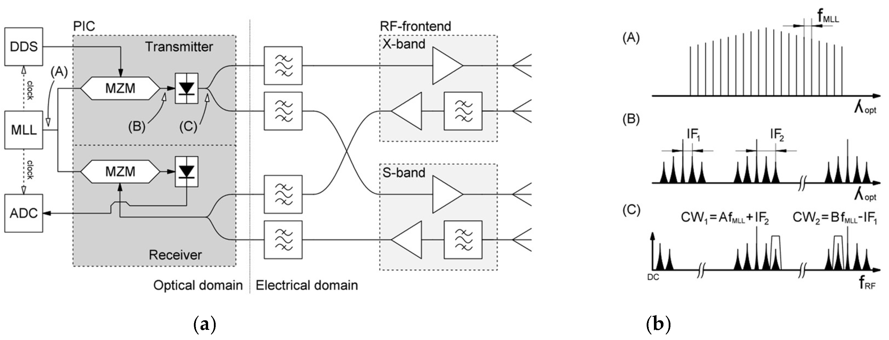
There are various methods to produce desired RF signals in photonic radar systems, but the most prevalent one is depicted in
Figure 1, showing a dual-band radar implementation [
8]. As an optical source, a mode-locked laser (MLL) is commonly utilized [
12]. Its output is made up of a series of phase-locked modes that create a comb-like spectrum with signals spaced by the laser repetition rate,
, as illustrated in
Figure 1-A. Direct digital synthesis (DDS) is applied to generate two desirable radar waveforms at different intermediate frequencies
and
. This signal then modulates a Mach-Zehnder modulator (MZM), resulting in the radar waveforms being mixed with an optical signal and appearing as lower- and upper-sidebands around each mode of the MLL (
Figure 1-B). When the modulated optical signal reaches the photodiode (PD), all of its spectral components are heterodyned together, resulting in a replicated IF signal separated precisely by the difference between the laser modes, up to the photodiode bandwidth (
Figure 1-C). Except for the DDS block, which is generally made using commercially available silicon chips, all components up to this point may be fabricated on a single photonic integrated circuit.
A narrow bandpass filter then extracts a single carrier frequency from the diode output. In a multi-band radar system, the signal is divided into two parts, and a separate filter is implemented at each designated frequency. After filtering, the signals are routed to two separate RF frontends with amplifiers and transmitting antennas. A single RF frontend in multi-band systems is typically not viable due to the difficulty of designing wideband amplifiers and antenna systems [
25,
26,
27].
Echoes from radar scattering are detected using narrowband antennas that are tuned to a certain frequency range and amplified by a frequency-selective low-noise amplifier. The signal from each stage is then filtered further with the optional narrow bandpass filter before being fed into the photonic receiver and linked together to generate a single line that modulates the MLL through another MZM. As a result, we do direct optical sampling of the high-frequency signal without using any down-conversion stages and with the MLL’s incredibly low jitter [
15]. The analog-to-digital converter (ADC) transforms the signal into the digital domain, where it is further processed. A more in-depth explanation of a photonic technique may be found in [
20].
2.2. Coherent Radar and Lidar System on a Single PIC
Although radars have become quite versatile while moving to a complex digital processing, they are still severely limited by their spatial resolution [
18,
28,
29,
30] . Only frequencies above 50 GHz enable precise radar detection that is usable in automotive avoiding systems [
1]. However, this limitation can be completely circumvented with lidar. While it offers superior angular resolution, its effectiveness is limited to favorable weather conditions and it cannot penetrate opaque objects [
28]. When combined with radar, this system becomes incredibly precise in estimating object location and velocity while being resilient to external effects [
7,
31]. It has been previously demonstrated that it is possible to build radar and lidar cores on a single PIC, thus significantly reducing the required space, power consumption and transmission coherence issues, since both units operate under the same laser source [
17].
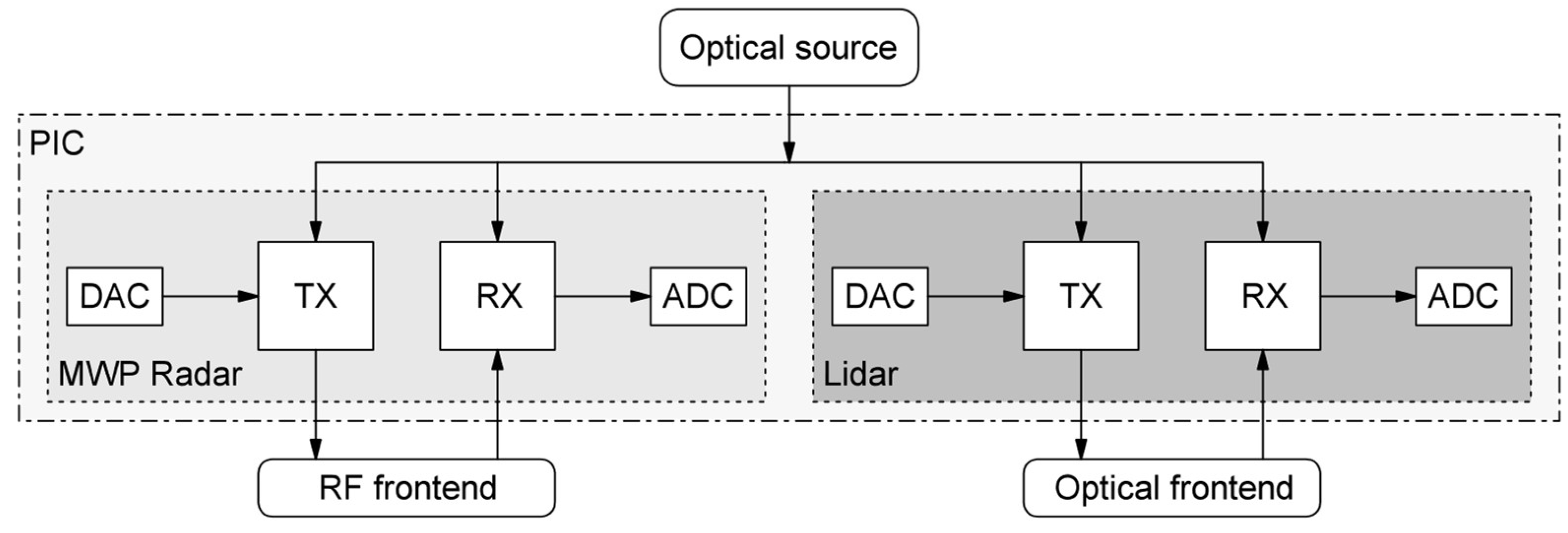
Figure 2 depicts a block diagram of the integrated system, in which the radar’s RF circuit (responsible for up- and down-conversion), has been replaced by an optical structure, a portion of which is shared with the lidar transceiver. They can be controlled with two individual DACs and sampled with another two ADCs simultaneously, avoiding the need for a synchronization process and resulting in a more precise imaging. A heterogeneous mix of lidar and radar may be employed in a novel photonics-based surveillance system to harness their complimentary qualities and offer data collection under uniform detection conditions, which is critical for accurate data fusion implementation [
7,
21,
31]. A separate RF front end, such as the one shown in
Figure 1, is however still required.
3. RF Front-End Requirements
Due to the PIC’s low output power, designing the radio front-end is more difficult than in traditional radar implementations. Normally, the output power of a high-frequency oscillator is around 0 dBm, but in microwave photonics, it is about 60 dB lower due to the losses in optical processing [
8,
16,
22,
23,
25,
32]. Similarly, the Mach-Zehnder modulator on the receiving side requires a suitably high input power. To detect a target with certainty at a distance of a few hundred meters, the entire amplification in the RF part, both on the receiving and transmitting sides, amounts to around 100 dB [
5]. A radio engineer faces a difficult task when attempting to achieve 100 dB of gain. Commercial designs, such as the N4985A used in [
32], are expensive, and creating amplifiers from scratch is both time-consuming as well as inconvenient. We do not want to damage the signal’s good phase noise and spectral purity by introducing excessive intermodulation distortion while pushing the amplifiers towards their saturation point. Another concern is the amplification of already weak radar scattering, which must not be exacerbated by the receiver’s inherent noise.
Above all, a low-noise amplifier is a component that aims for a low noise figure, high amplification, and perfect input/output match to achieve the unconditional stability of an active device. Unfortunately, the requirements are mutually exclusive, which means that one of the parameters, generally the input match, must be sacrificed [
24]. Connecting several LNA amplifiers in series quickly results in an unstable amplifier chain that self-oscillates and renders the radar inoperable. The problem is further aggravated when we want to maintain stability across a wide frequency range and need more than two amplifiers connected in series due to the necessity for high amplification.
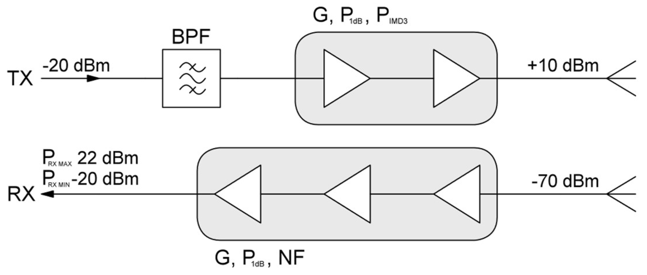
Figure 3 illustrates the output and input power requirements of the most recent optical radar structures. The inclusion of a transimpedance amplifier straight after the photodiode in the transmitter (TX) stage produces a 40 dB greater output signal, considerably simplifying the design of the subsequent stage. To obtain the desired +10 dBm output level, an extra 30 dB of gain is required, which may be obtained with the two amplifiers following the bandpass filter. A good safety margin would be to choose these components such that the compression point is greater than +15 dBm and the IP3 value is 10 dB higher, indicating that we are operating in a safe (linear) region [
24].
Because the PIC structure has no extra amplifiers, the receiving side (RX) needs around 60 dB of amplification. The gain of an LNA amplifier in this frequency range (X-band) is often less than 20 dB, necessitating at least three stages, or mixing signal down to a lower IF. As the input match of those devices is usually poor, additional circuitry is required, limiting the frequency response to a narrow band. It is extremely unlikely to reach saturation point in normal operating conditions, hence greatly reducing any significant intermodulation distortion possibility, and only the noise figure is of particular concern. This should be kept as low as feasible, preferably less than 1.5 dB [
4].
4. RF front-End Design and Results
To validate the proposed radar architecture and concentrate on the subsequent RF front-end’s performance, the signal path was divided into signal generation, amplification, transmission, reception, conversion, and data analysis. Initially, X-band signal generation using optical heterodyne mixing was demonstrated to assess achievable output power, phase noise, and long-term stability. Subsequently, a complete X-band RF front-end was constructed and evaluated. Received signals were then digitized and processed to showcase the capability of generating Doppler fingerprints of rotor blades during a power-up sequence.
4.1. Optically Genrated RF Signal
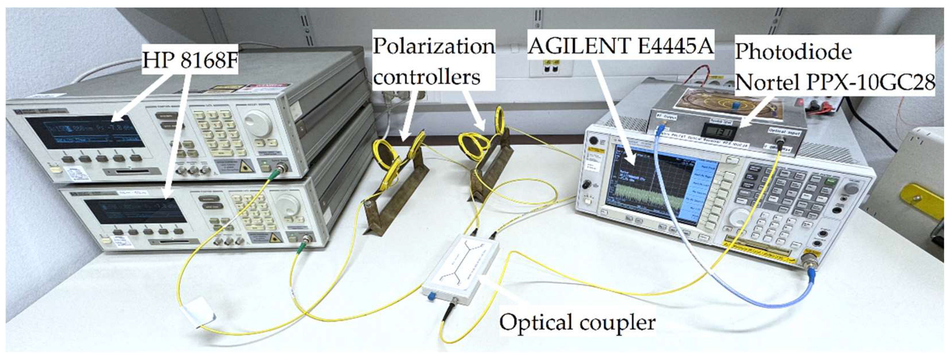
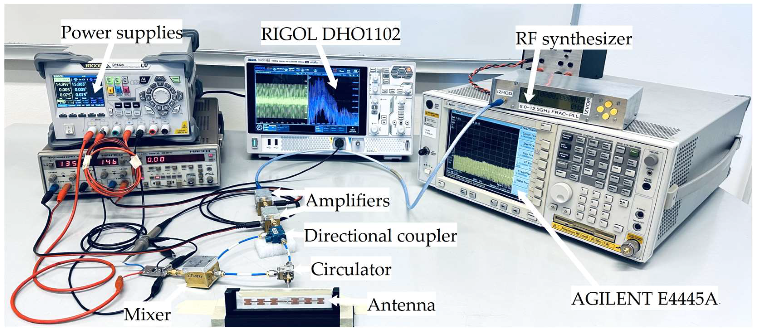
Figure 4 illustrates the measurement setup employed to evaluate stable optical generation of X-band signals. Two laser sources (HP 8168F) were utilized to simulate the optical spectrum after a MZM (following the configuration depicted in
Figure 1). Prior to coupling the two signals into a single fiber optic cable, manual polarization controllers were incorporated to exert additional control over the polarization at the photodiode surface. Optical power levels were then adjusted to optimize the photodiode current (around 600 µA), thereby achieving the optimal phase noise performance of the RF signal produced at the photodiode output. This signal was subsequently observed and measured using the Agilent E4445A spectrum analyzer.
Although it is entirely feasible to use such a generated signal directly in the subsequent RF output stage, the signal parameters were reconstructed using a specially designed X-band RF synthesizer to circumvent the lengthy warm-up time of the HP8168F laser sources and polarization fluctuations encountered when handling the optical cables of the measurement setup (which would not be a concern when using a PIC structure) [
33].
4.2. RF Frontend
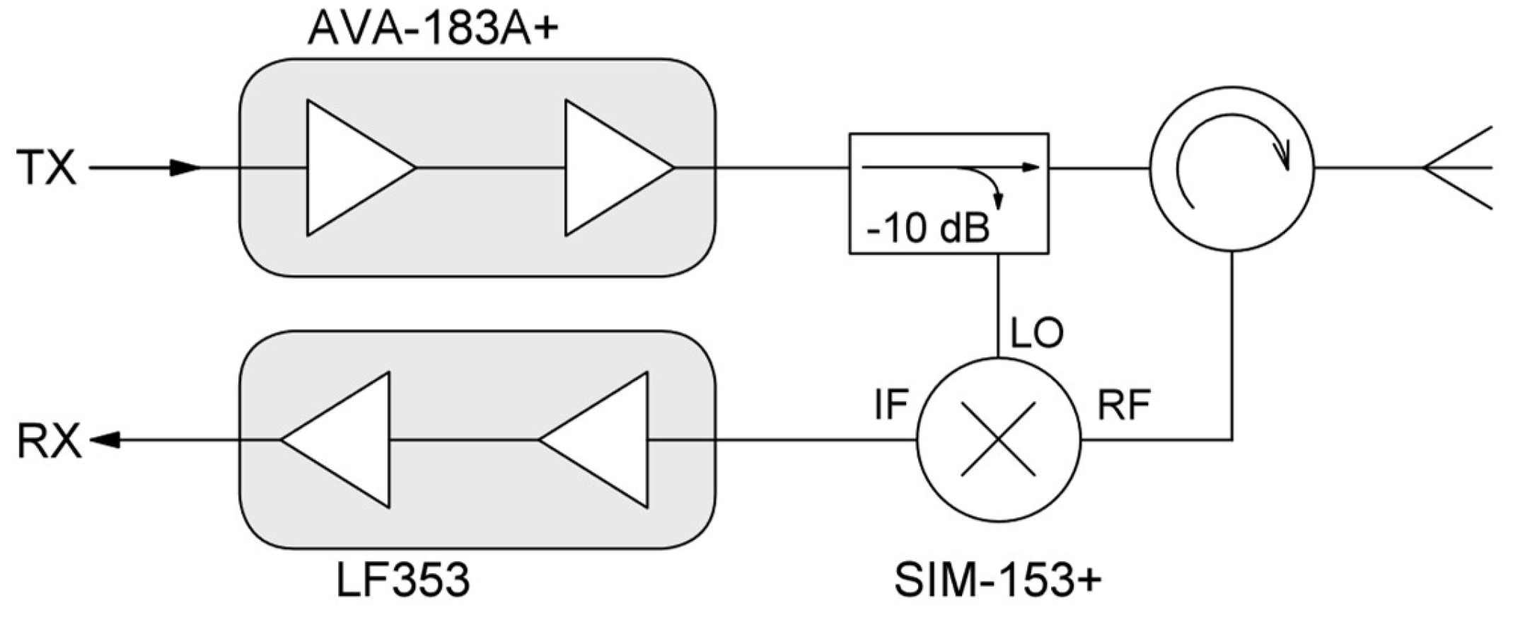
Given the relatively low signal output from the PIC, amplification was necessary prior to transmission. To achieve this, two AVA-183A+ amplifiers were employed, as depicted in
Figure 5. Renowned for their minimal phase noise contribution, typically -151 dBc/Hz at a 10 kHz offset [
34], these amplifiers possess high linearity and low phase noise degradation, making them ideal candidates for radar applications. The amplifiers’ ability to minimize signal degradation and distortion is crucial for maintaining optimal system performance.
Following amplification, the signal was then routed through a directional coupler. While two antennas are commonly used in radar systems (to minimize costs), transmission and reception can be achieved with a single antenna using a circulator. The scattered signal was then routed to the SIM-153+ mixer along with a reference signal from the directional coupler. A coupling of -10 dB was selected to achieve suitable LO levels while adhering to the ISM region limitations given the signal levels and antenna gain (achievable EIRP).
The resulting mixing product was subsequently amplified using a low-noise, low-frequency two-stage amplifier, elevating the signal levels to a range suitable for the signal digitalization and FFT analysis. Each amplification stage was built around a LF353 J-FET wideband dual operational amplifier, each providing approximately 20 dB of voltage gain (40 dB of power gain), while remaining stable even in the absence of an input signal (self-oscillation) or excessive scattering from the object (saturation). The final output signal was then digitized and analyzed using the integrated functions of a Rigol DHO1102 oscilloscope.
Figure 6 illustrates the final measurement setup, with the antenna located at the front of the desk.
4.3. Antenna Design
To validate the proposed RF front-end design and conduct performance measurements, a specialized narrowband antenna was designed and fabricated on a lightweight high-frequency laminate. To mitigate the frequency dependence inherent in serially connected antenna array elements, the antenna structure was divided into two parallel-connected elements, thereby reducing main lobe frequency steering, as illustrated in
Figure 7.
To achieve a directivity of approximately 18 dBi, a rectangular 1×6 element patch antenna array was selected. The dimensions of each patch were calculated based on the target frequency and subsequently optimized through simulation. A coaxial probe-fed technique was employed, with a microstrip line feeding each group. The feed line of one group was extended (non-symmetrical structure) to ensure constructive beam summation.
To optimize radiation efficiency, careful consideration was given to the substrate material. A low dielectric constant and appropriate substrate thickness are critical factors in antenna performance [
35]. The Rogers RO4350B laminate was chosen due to its dielectric constant of 3.48 and thickness of 0.51 mm, striking a balance between performance and the physical constraints imposed on the final antenna [
36].
Figure 8 depicts one half of the final prototype antenna structure, with all dimensions provided in mm.
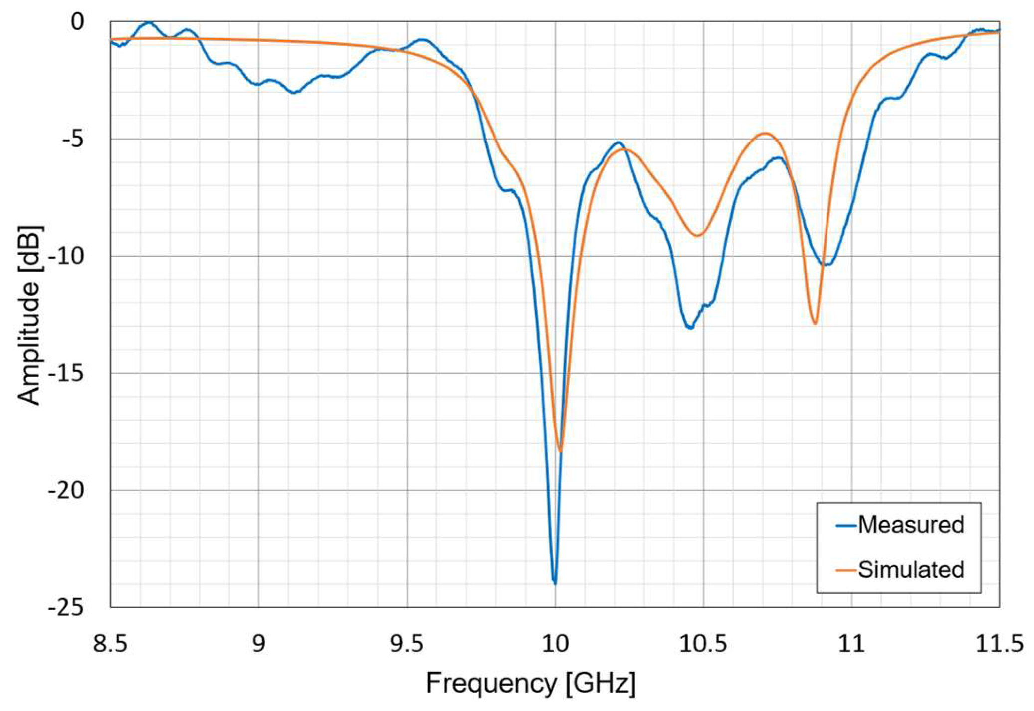
The antenna’s radiation pattern and S11 parameter were both simulated and measured to verify performance. Measurement of the S11 parameter was conducted on a Rohde & Schwarz ZVA-67 vector network analyzer. As shown in
Figure 9, the antenna exhibits optimal performance around 10 GHz, as designed. Input matching remains below -6 dB within approximately Δ400 MHz of bandwidth and below -10 dB for Δ180 MHz. The antenna design significantly enhances the rejection of higher harmonics generated by the PIC structure, in conjunction with the MLL and MZ modulator.
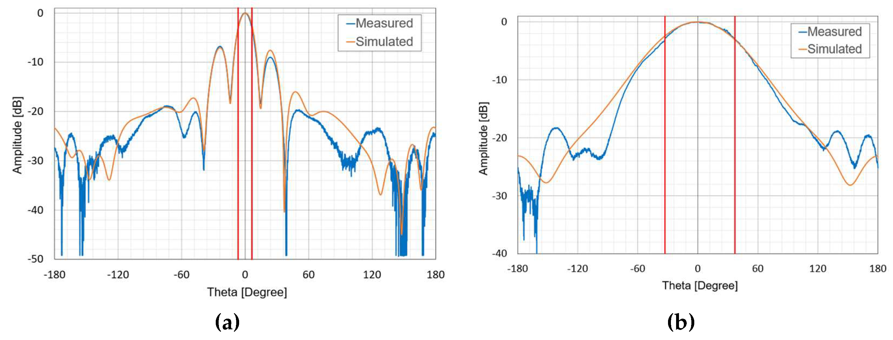
The radiation pattern, presented in
Figure 10, demonstrates minimal back lobe radiation, as expected for patch antennas, although some side lobes were observed. These side lobes are within acceptable limits for seamless operation of continuous-wave (CW) radars. Notably, the overlapping beams (from two parallelly excited halves of the patch antenna arrays) focus the majority of the radiated power at theta = 0°, with a Half-Power Beamwidth (HPBW) marked by the red lines in
Figure 10, indicating a 3 dB drop in the main lobe amplitude at the designed frequency of 10 GHz.
4.4. Performance Analysis
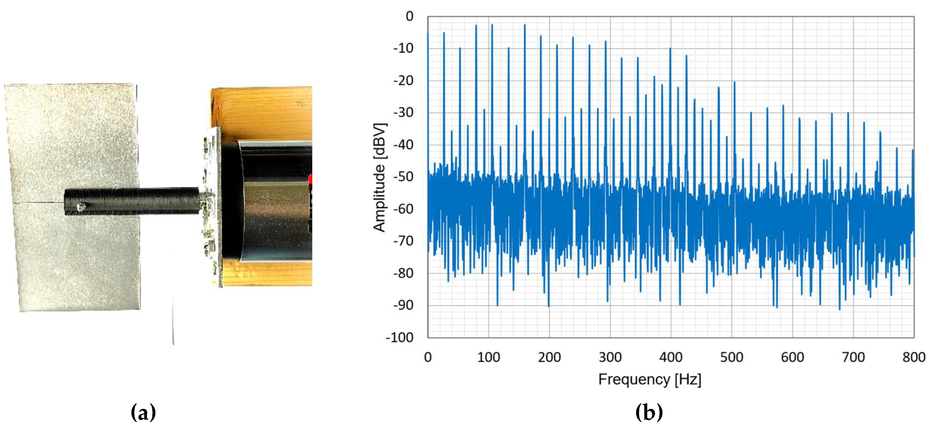
To assess the performance of the demonstrated radar system, a controlled moving target with known characteristics was required to measure the Doppler response. A servo motor equipped with a rectangular blade was selected due to its precise control over both rotational speed and blade dimensions. The experimental setup for the rotor is depicted in
Figure 11, along with the FFT analysis of the scattered signal received by the proposed RF front-end system shown in
Figure 6.
FFT analysis, depicted in
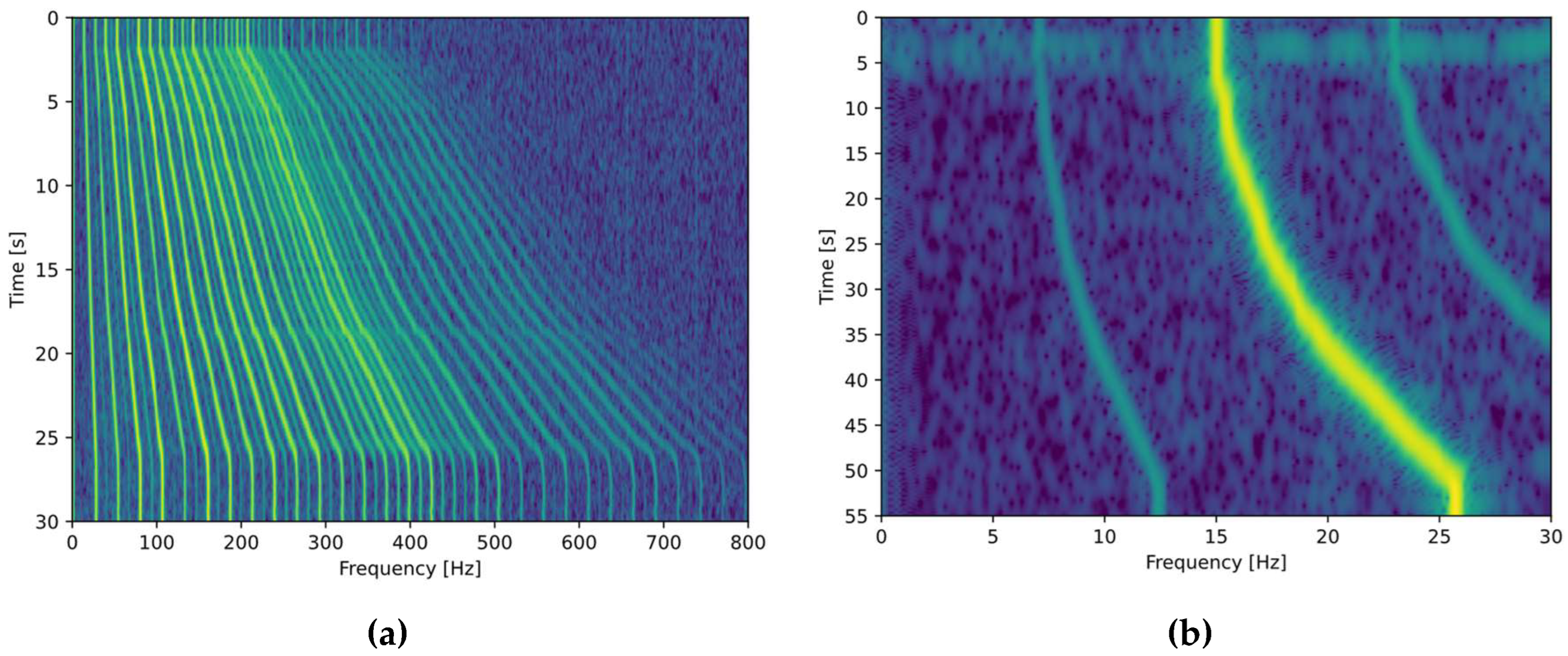
Figure 11, reveals distinct frequency peaks corresponding to reflections from various sections of the blade, each rotating at a unique angular velocity. The differential Doppler shifts observed across the blade’s radial extent, from the rotor shaft to the tip, are a direct consequence of varying velocity. As the rotor speed increases, the frequency response undergoes a corresponding dilation, as illustrated in
Figure 12(a) where the rotational velocity is elevated from 16 to 26 revolutions per second. This distinctive frequency signature serves as a reliable Doppler-based identifier for the rotor blade in scenarios such as throttling up during a lift-off sequence or climbing to a higher altitude, and can be considered a UAV Doppler signature.
5. Discussion
This study validates the feasibility of a robust RF front-end chain for microwave photonic radar systems, especially those employing photonic integrated circuits as core components. The primary goal was to demonstrate the RF front-end’s ability to maintain signal integrity despite PIC limitations like low output power and high optical processing losses.
As shown in
Figure 12, the system can detect a moving propeller and measure FFT bins with a resolution as low as Δ 0.5 Hz. While further research is needed to classify all moving parts of an UAV (all rotor blades), our results indicate that this is achievable with a PIC-based RF signal generation, which requires additional amplification stages compared to traditional electronic radar systems. Excessive signal degradation in the amplification stage would result in a Doppler’s fingerprint diagram that is indistinguishable from other moving objects, such as those that do not generate multiple Doppler-shifted frequencies (moving car, glider plane). As depicted in
Figure 12(b), the system is sensitive enough to detect both Doppler shifts of the rotating blade: the upper part moving towards the radar and the lower part moving away. The system’s lack of a quadrature mixer with I and Q paths prevents the differentiation of individual scattered frequencies. Consequently, the is also a summation of both, with the highest magnitude resulting from their combined effect.
The custom-designed RF front-end effectively addressed challenges such as low signal strength and the need for high-gain amplification while ensuring stability and minimizing noise. By carefully selecting amplifiers like the AVA-183A+, which contributes minimal phase noise, we demonstrated that high-performance amplification is achievable even in systems where optical-to-electrical conversion introduces additional losses and distortions.
This work establishes a foundation for further integration of photonic components into RF systems, particularly for frequency-agile radar designs where traditional electronic systems may be inadequate. The validation of the RF front-end chain opens up new possibilities for the development of fully integrated photonic radar systems (with synchronous radar and lidar transmission), potentially leading to more compact, efficient, and cost-effective solutions in advanced radar applications.
Future research will focus on system miniaturization and integration onto a single PCB structure for use on UAV drones as part of in-flight hostile object detection and classification.
Author Contributions
Conceptualization, A.B. and B.B.; Methodology, A.B.; Validation, A.B.; Investigation, A.B. and L.Z.; Data curation, L.Z.; Writing—original draft preparation, A.B.; Writing—review and editing, L.Z..; Visualization, A.B. and L.Z.; Supervision, B.B. All authors have read and agreed to the published version of the manuscript.
Funding
This research is supported by NATO multiyear project CLARIFIER - SPS.MYP G5888 and by the Slovenian Research and Innovation Agency (ARIS), grant numbers V2-24005 and J2-50072 and research core funding No. P2-0246.
Data Availability Statement
Not applicable.
Conflicts of Interest
The authors declare no conflicts of interest.
References
- Waldschmidt, C.; Hasch, J.; Menzel, W. Automotive Radar — From First Efforts to Future Systems. IEEE J. Microw. 2021, 1, 135–148. [CrossRef]
-
Principles of Modern Radar; Richards, M.A., Scheer, J., Holm, W.A., Melvin, W.L., Eds.; SciTech Pub: Raleigh, NC, 2010; ISBN 978-1-891121-52-4.
- Hakobyan, G.; Yang, B. High-Performance Automotive Radar: A Review of Signal Processing Algorithms and Modulation Schemes. IEEE Signal Process. Mag. 2019, 36, 32–44. [CrossRef]
- Skolnik, M.I. Introduction to Radar Systems; McGraw-Hill electrical engineering series; Third edition.; McGraw Hill: Boston, Mass. Burr Ridge, IL Dubuque, IA, 2001; ISBN 978-0-07-288138-7.
-
Radar Handbook; Skolnik, M.I., Ed.; 3rd ed.; McGraw-Hill: New York, 2008; ISBN 978-0-07-148547-0.
- Ghelfi, P.; Laghezza, F.; Scotti, F.; Serafino, G.; Capria, A.; Pinna, S.; Onori, D.; Porzi, C.; Scaffardi, M.; Malacarne, A.; et al. A Fully Photonics-Based Coherent Radar System. Nature 2014, 507, 341–345. [CrossRef]
- Onori, D.; Laghezza, F.; Scotti, F.; Scaffardi, M.; Bogoni, A. Coherent Radar/Lidar Integrated Architecture. In Proceedings of the 2015 European Radar Conference (EuRAD); IEEE: Paris, France, September 2015; pp. 241–244.
- Scotti, F.; Onori, D.; Laghezza, F. Fully Coherent S- and X-Band Photonics-Aided Radar System Demonstration. IEEE Microw. Wireless Compon. Lett. 2015, 25, 757–759. [CrossRef]
- Batagelj, B.; Bogataj, L.; Vidmar, M. Key Properties and Design Issues for an Opto-Electronic Oscillator. In Proceedings of the 2015 17th International Conference on Transparent Optical Networks (ICTON); IEEE: Budapest, July 2015; pp. 1–4.
- Serafino, G.; Scotti, F.; Lembo, L.; Hussain, B.; Porzi, C.; Malacarne, A.; Maresca, S.; Onori, D.; Ghelfi, P.; Bogoni, A. Toward a New Generation of Radar Systems Based on Microwave Photonic Technologies. J. Lightwave Technol. 2019, 37, 643–650. [CrossRef]
- Tang, Z.; Li, Y.; Yao, J.; Pan, S. Photonics-Based Microwave Frequency Mixing: Methodology and Applications. Laser & Photonics Reviews 2020, 14, 1800350. [CrossRef]
- Ghelfi, P.; Laghezza, F.; Scotti, F.; Serafino, G.; Pinna, S.; Onori, D.; Lazzeri, E.; Bogoni, A. Photonics in Radar Systems: RF Integration for State-of-the-Art Functionality. IEEE Microwave 2015, 16, 74–83. [CrossRef]
- Capmany, J.; Novak, D. Microwave Photonics Combines Two Worlds. Nature Photon 2007, 1, 319–330. [CrossRef]
- Pan, S.; Zhang, Y. Microwave Photonic Radars. J. Lightwave Technol. 2020, 38, 5450–5484. [CrossRef]
- Laghezza, F.; Scotti, F.; Ghelfi, P.; Bogoni, A.; Pinna, S. Jitter-Limited Photonic Analog-to-Digital Converter with 7 Effective Bits for Wideband Radar Applications. In Proceedings of the 2013 IEEE Radar Conference (RadarCon13); IEEE: Ottawa, ON, Canada, April 2013; pp. 1–5.
- Yoo, S.; Bae, Y.; Jang, S. Design of Wideband FMCW Radar Transceiver System Using Photonic Elements. Micromachines 2023, 14, 1296. [CrossRef]
- Falconi, F.; Melo, S.; Scotti, F.; Malik, M.N.; Scaffardi, M.; Porzi, C.; Ansalone, L.; Ghelfi, P.; Bogoni, A. A Combined Radar & Lidar System Based on Integrated Photonics in Silicon-on-Insulator. J. Lightwave Technol. 2021, 39, 17–23. [CrossRef]
- Cui, S.L.Z.; Ye, X.; Feng, J.; Yang, Y.; He, Z.; Cong, R.; Zhu, D.; Zhang, F.; Pan, S. Chip-Based Photonic Radar for High-Resolution Imaging 2019.
- Scotti, F.; Porzi, C.; Ghelfi, P.; Falconi, F.; Amir, M.M.H.; Maresca, S.; Borgarino, M.; Bogoni, A. Indoor Field-Trial in X Band of a Photonics-Based Multiband Radar on a Packaged Silicon Chip. In Proceedings of the 2021 International Topical Meeting on Microwave Photonics (MWP); IEEE: Pisa, Italy, November 15 2021; pp. 1–4.
- Scotti, F.; Laghezza, F.; Ghelfi, P.; Bogoni, A. Multi-Band Software-Defined Coherent Radar Based on a Single Photonic Transceiver. IEEE Trans. Microwave Theory Techn. 2015, 63, 546–552. [CrossRef]
- Vercesi, V.; Onori, D.; Laghezza, F.; Scotti, F.; Bogoni, A.; Scaffardi, M. Frequency-Agile Dual-Frequency Lidar for Integrated Coherent Radar-Lidar Architectures. Opt. Lett. 2015, 40, 1358. [CrossRef]
- Zhu, D.; Chen, W.; Chen, Z.; Du, T.; Tang, Z.; Pan, S. RF Front-End Based on Microwave Photonics. In Proceedings of the 2017 Opto-Electronics and Communications Conference (OECC) and Photonics Global Conference (PGC); IEEE: Singapore, July 2017; pp. 1–3.
- Laghezza, F.; Scotti, F.; Ghelfi, P.; Bogoni, A.; Banchi, L.; Malaspina, V.; Serafino, G. Photonic Based Marine Radar Demonstrator. In Proceedings of the 2015 IEEE Radar Conference (RadarCon); IEEE: Arlington, VA, USA, May 2015; pp. 0226–0230.
- Rohde, U.L.; Newkirk, D.P. RF/Microwave Circuit Design for Wireless Applications; J. Wiley & Sons: New York, 2000; ISBN 978-0-471-29818-2.
- Wang, X.; Cao, F.; Ma, C.; Yang, Y.; Zhang, F.; Pan, S. Dual-Band Coherent Microwave Photonic Radar Using Linear Frequency Modulated Signals With Arbitrary Chirp Rates. IEEE J. Select. Topics Quantum Electron. 2023, 29, 1–9. [CrossRef]
- Serafino, G.; Maresca, S.; Porzi, C.; Scotti, F.; Malacarne, A.; Amir, M.M.H.; Ghelfi, P.; Bogoni, A. Maritime Field Trial of a Dual-Band Silicon Integrated Photonics-Based Radar. IEEE J. Select. Topics Quantum Electron. 2022, 28, 1–10. [CrossRef]
- Fan, B.; Zhang, F.; Ma, C.; Yang, Y.; Pan, S.; Wang, X. Microwave Photonic Bistatic Radar for Real-Time and High-Resolution Imaging. IEEE Photon. Technol. Lett. 2020, 32, 1397–1400. [CrossRef]
- McManamon, P.F. LiDAR Technologies and Systems; SPIE, 2019; ISBN 978-1-5106-2539-6.
- Reza, M.; Maresca, S.; Scotti, F.; Pandey, G.; Imran, M.; Serafino, G.; Amir, M.H.; Camponeschi, F.; Ghelfi, P.; Bogoni, A.; et al. Multi-Static Multi-Band Synthetic Aperture Radar (SAR) Constellation Based on Photonic Processing. In Proceedings of the 2022 IEEE International Topical Meeting on Microwave Photonics (MWP); IEEE: Orlando, FL, USA, October 2022; pp. 1–4.
- Borowski, T.; Pasternak, M.; Pietrasinski, J. The Photonic Radar: The Situation Today and the Prospects for the Future. In Proceedings of the Radioelectronic Systems Conference 2019; Kaniewski, P., Matuszewski, J., Eds.; SPIE: Jachranka, Poland, February 11 2020; p. 52.
- Scotti, F.; Onori, D.; Scaffardi, M.; Lazzeri, E.; Bogoni, A.; Laghezza, F. Multi-Frequency Lidar/Radar Integrated System for Robust and Flexible Doppler Measurements. IEEE Photon. Technol. Lett. 2015, 27, 2268–2271. [CrossRef]
- Wang, A.; Zheng, D.; Du, S.; Zhang, J.; Du, P.; Zhu, Y.; Cong, W.; Luo, X.; Wang, Y.; Dai, Y. Microwave Photonic Radar System with Ultra-Flexible Frequency-Domain Tunability. Opt. Express 2021, 29, 13887. [CrossRef]
- Blatnik, A.; Batagelj, B. Wideband Low Phase-Noise Signal Generation Using Coaxial Resonator in Cascaded Phase Locked Loop. Electronics 2024, 13, 1934. [CrossRef]
- Mini-Circuits Monolithic Amplifier AVA-183A+ 2023.
-
Antenna Engineering Handbook; Volakis, J.L., Johnson, R.C., Jasik, H., Eibert, T.F., Yo, D.M.K.A., Emrick, R., Sahalos, J.N., Tai, C.-T., Long, S.A., Smith, G.S., Best, S.R., Jackson, D.R., Kempel, L.C., et al., Eds.; McGraw-Hill’s AccessEngineering; 4th ed.; McGraw-Hill: New York, 2007; ISBN 978-0-07-147574-7.
- Antenna Theory: Analysis and Design - Patch Antenna. In Antenna theory: analysis and design; Wiley: Hoboken, New Jersey, 2016; p. 782 ISBN 978-1-118-64206-1.
|
Disclaimer/Publisher’s Note: The statements, opinions and data contained in all publications are solely those of the individual author(s) and contributor(s) and not of MDPI and/or the editor(s). MDPI and/or the editor(s) disclaim responsibility for any injury to people or property resulting from any ideas, methods, instructions or products referred to in the content. |
© 2024 by the authors. Licensee MDPI, Basel, Switzerland. This article is an open access article distributed under the terms and conditions of the Creative Commons Attribution (CC BY) license (http://creativecommons.org/licenses/by/4.0/).
