1. Introduction
The growing environmental concerns associated with non-biodegradable plastics have driven the development for biodegradable alternatives derived from renewable resources. These biodegradable polymers, whether naturally derived or synthetically produced, are increasingly used in diverse applications such as textiles [
1], food packaging [
2], tissue engineering [
3], drug delivery [
4], and 3D printing [
5]. Their widespread use is mainly attributed to their biocompatibility and reduced environmental impact.
Polylactic acid (PLA), a biodegradable thermoplastic polymer derived from renewable resources like corn and sugarcane, is widely used due to its good mechanical strength and biocompatibility. However, PLA exhibits brittleness and poor ductility at room temperature, limiting its applications. Traditionally, plasticizers are added to improve flexibility [
6], but they can compromise biocompatibility and increase costs. Therefore, alternative methods are needed to reduce the brittleness and stiffness of PLA.
Using polymer blends is an effective strategy to achieve the desired functional properties in PLA [
7]. Blending PLA with other polymers allows for the combination of complementary properties, enhancing the overall performance of the material. This approach can significantly improve the flexibility, toughness, and processability of PLA without the complexities associated with synthesizing new copolymers. While copolymer synthesis involves intricate chemical reactions and precise control over monomer compositions, polymer blending offers a more straightforward and cost-effective solution. Polymer blends can be tailored to specific applications, such as increasing flexibility, enhancing biodegradability, and improving mechanical strength, making them a versatile and sustainable alternative to copolymer synthesis.
In this study, polycaprolactone (PCL) and polyethylene oxide (PEO) were used to form polymer blends with PLA. PCL is a biodegradable polyester known for its low melting point and excellent flexibility, while PEO is a hydrophilic, biodegradable polymer with good biocompatibility and flexibility. Furthermore, to investigate the influence of processing methods on the mechanical properties of PLA and its blends, we employed two processing methods for fabricating their films: electrospinning and solvent casting.
Electrospinning is a versatile technique for producing ultrafine fibers at the nanometer scale by using an electric field to draw a charged polymer solution. As the charged solution travels toward a grounded collector, rapid solvent evaporation plays a critical role in fiber formation. This evaporation solidifies the polymer, while the continuous stretching of the jet under the electric field ensures the formation of long, thin fibers. Electrospinning generates non-woven fibrous membranes with high surface area-to-volume ratios and controllable fiber orientations [
8,
9]. Previous studies have demonstrated that electrospinning can significantly improve the mechanical properties of polymer blends. For instance, it has been shown to enhance the flexibility and elongation of PCL/PHBV blends [
10] and PCL films [
7], and increase the Young's modulus in PLA films [
4].
Solvent casting, on the other hand, is a commonly used technique for fabricating thin polymer films by dissolving a polymer in an appropriate solvent and then casting the solution onto a flat surface [
11]. As the solvent gradually evaporates, the polymer precipitates, resulting in the formation of a solid, uniform film. This method is valued for its simplicity and versatility. It enables the production of films with varying degrees of crystallinity based on the solvent's evaporation rate [
5,
12]. Solvent casting provides a baseline for comparison, enabling the evaluation of how different microstructure and crystallinity levels affect the mechanical properties and hydrophilicity of the films.
The objective of this study is to improve the mechanical behaviors of PLA by blending it with PEO and PCL. Specifically, we examined the mechanical properties of neat PLA and PLA blend films fabricated using both electrospinning and solvent casting. A series of analytical techniques were employed for comparison, including scanning electron microscopy (SEM) to assess surface morphology, Fourier transform infrared spectroscopy (FTIR) to detect potential changes in chemical structure, differential scanning calorimetry (DSC) to evaluate thermal properties and crystallinity, X-ray diffraction (XRD) to analyze molecular orientation, uniaxial tensile testing to measure mechanical properties, water contact angle measurements to assess surface hydrophilicity, and atomic force microscopy (AFM) to analyze nanoscale features of the fiber surface. The findings of this study may provide valuable insights for the development of PLA-based films tailored to specific applications.
2. Materials and Methods
2.1. Materials
Polylactic acid (PLA) (Ingeo 3001D, Mn = 100,000) was obtained from NatureWorks. Polycaprolactone (PCL) (Mn = 80,000) and polyethylene oxide (PEO) (Mn = 100,000) were purchased from Sigma-Aldrich. Both dichloromethane (DCM) and dimethylformamide (DMF) were of 99% purity and were obtained from Macron.
2.2. Electrospinning Setup
The electrospinning setup consisted of a syringe pump (KDS-210, KD Scientific, USA), a high-voltage power supply (AU-30P1-LC, Matsusada Precision Inc., Japan), and a grounded rotating drum (diameter 102 mm). A crank-slider mechanism was designed and employed to provide the reciprocating motion of the spinneret, ensuring a uniform film thickness. The voltage difference between the positively charged spinneret and the grounded collector was controlled by the high-voltage power supply. The flow rate was precisely controlled by the syringe pump, and the drum's rotational speed was adjusted using the DC power supply. The working distance was adjustable.
2.3. Preparation of Electrospun Films
To prepare the polymer solutions for electrospinning, polymers were dissolved in a 70:30 volumetric mixture of DCM and DMF. DCM, with its high volatility, promotes rapid fiber solidification, while DMF stabilizes the electrospinning process due to its low volatility and higher conductivity. A 24 wt% solution was used to electrospin neat PLA. The electrospinning parameters were set to a voltage to 13-16 kV, with a flow rate of 4.8 ml/h, and a working distance of 15 cm between the spinneret and the collector. The electrospun fibers were collected for 90 min to form a uniform film. PLA was also solvent blended with PCL or PEO at weight ratios of 1:1 and 1:2 for each blend. The total polymer concentration was 15 wt% for the PLA/PCL blends and 24 wt% for the PLA/PEO blends. For the electrospinning of PLA blends, the voltage was adjusted to 14-18 kV to maintain a stable Taylor cone, while the other parameters remained the same as those used for neat PLA. In a pilot study, a 2:1 PLA/PCL blend was also prepared; however, phase separation occurred and this ratio was not pursued further.
2.4. Preparation of Solvent-Cast Films
Solvent-cast films were prepared using the same polymer solutions as those used for electrospinning for comparison. The solution was poured into a Teflon dish and covered with a size-matched glass funnel to suppress evaporation [
7]. The solvent was allowed to evaporate at room temperature for 24 h, followed by an additional 24 h in a vacuum chamber to remove any residual solvents.
2.5. Characterization of the Films
2.5.1. Scanning Electron Microscopy
Scanning Electron Microscopy (SEM) was employed to observe the surface morphology of the films. SEM was conducted using a Phenom ProX SEM. Samples (7 mm × 7 mm) were sputter-coated with platinum to enhance conductivity. The fiber diameter and its distribution were analyzed using ImageJ software, measuring 150 fibers from five SEM images for each group.
2.5.2. Fourier-Transform Infrared Spectroscopy (FTIR)
FTIR spectra were recorded using a Thermo Scientific Nicolet 6700 FTIR spectrometer equipped with an ATR module. The parameters were set to 64 scans per minute, 2 cm-1 resolution, and a wavenumber range of 600-4000 cm-1.
2.5.3. X-Ray Diffraction Analysis (XRD)
XRD analysis was performed using a Bruker AXS GmbH D8 Advance X-ray diffractometer with Cu Kα radiation (1.5418 Å). The scanning range was 10-80°, with a step size of 0.025°/step and a counting time of 0.21 seconds/step.
2.5.4. Differential Scanning Calorimetry (DSC)
DSC measurements were conducted using a TA Instruments DSC Q200 equipped with an RCS cooling system. Samples (3-5 mg) were cooled to 0°C and then heated to 200°C at a rate of 10 °C/min. The melting temperature (
), cold crystallization temperature (
), melting enthalpy (
), and cold crystallization enthalpy (
) were recorded. The crystallinity degree for PLA, PCL, and PEO in the blends were calculated using the following equations.
where
,
, and
represent the weight fractions of PLA, PCL, and PEO in the blends, respectively. The theoretical melting enthalpy for PLA,
, was assumed to be 93 J/g [
13,
14], for PCL,
, it was assumed to be 139.5 J/g [
15,
16], and for PEO,
, it was assumed to be 213.5 J/g [
17]. For neat polymer,
1.
2.5.5. Uniaxial Tensile Testing
Dog bone-shaped specimens were prepared by punching the films with a miniature ASTM D412-C die (gauge length: 16.5 mm; width: 3 mm). Tensile tests were performed using a custom-built mechanical tester equipped with a 1000-g load cell (WMCP-1000G, Interface, Scottsdale, AZ). The specimens were stretched to failure at a strain rate of 0.0005 s
-1. The stretch ratio along the loading direction was determined by tracking the positions of twelve markers placed on the central surface of the specimen, relative to their positions in the unloaded state [
18]. The stress in the central region, where the stretch ratio was measured, was calculated from the tensile force recorded by the load cell and the deformed cross-sectional area at the center of the specimen. The Young's modulus, elongation at break, and ultimate strength were derived from the resulting stress-stretch curves.
2.5.6. Contact Angle Measurement
Water contact angle measurements were performed using an FTA125 contact angle goniometer. Deionized water droplets (5 μL) were placed on electrospun and solvent-cast films. The contact angle was measured for five samples of each type to assess hydrophilicity or hydrophobicity.
2.5.7. Atomic Force Microscopy (AFM)
AFM analysis was performed using an SPA-300HV AFM (SII Nanotechnology Inc.) in tapping mode with HI'RES-C18/CR-AU probes. Amplitude imaging captured the topography of electrospun fibers, while phase imaging revealed details about their crystalline structure and molecular chain alignment within the fibers.
2.6. Statistical Analysis
All data were reported as mean ± standard deviation. One-way ANOVA in conjunction with Tukey post hoc procedure was performed to access the difference between groups, with * indicating p < 0.05 and ** indicating p < 0.001.
3. Results and Discussion
3.1. PLA
3.1.1. Surface Morphology of the PLA Films
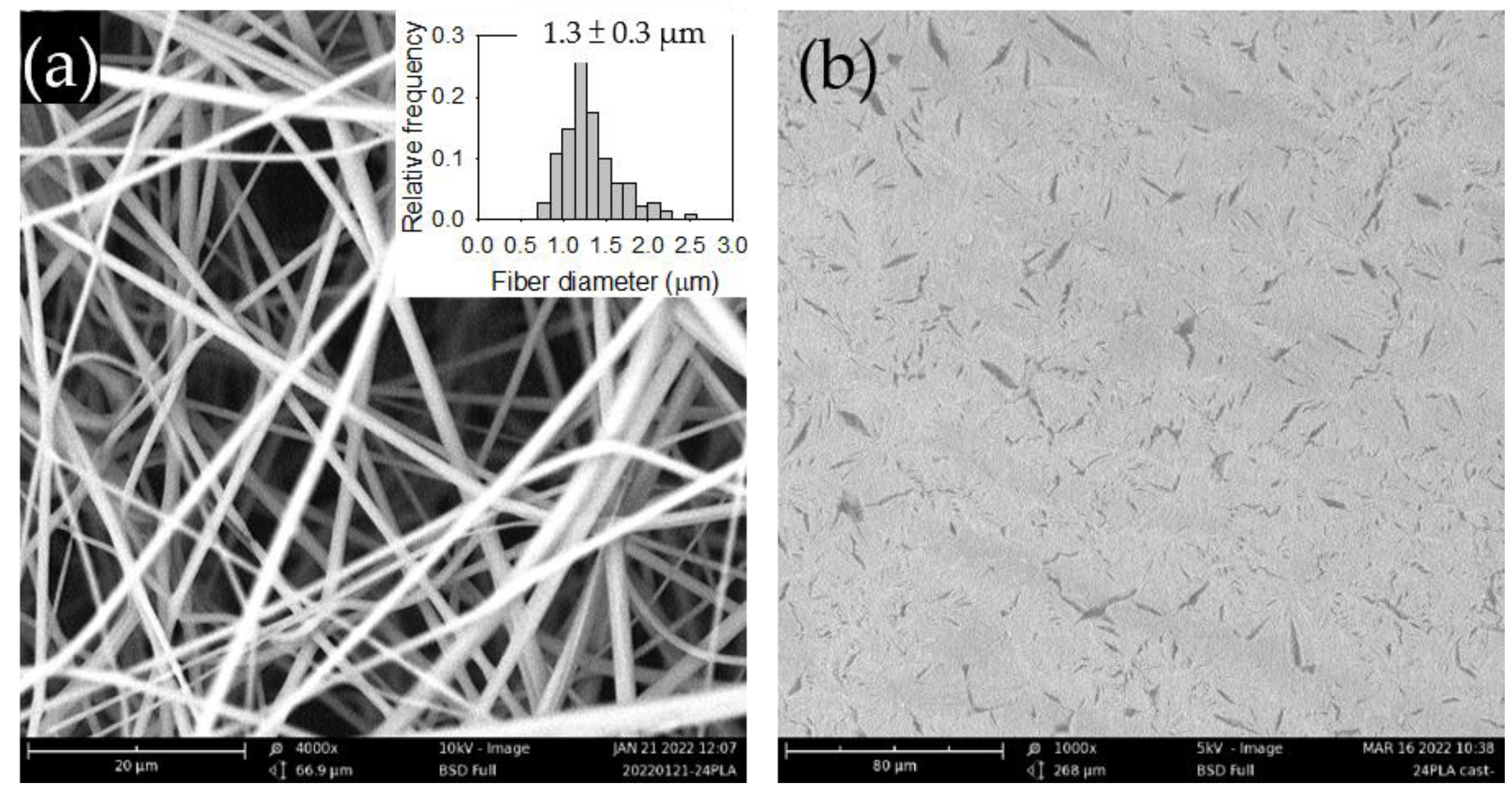
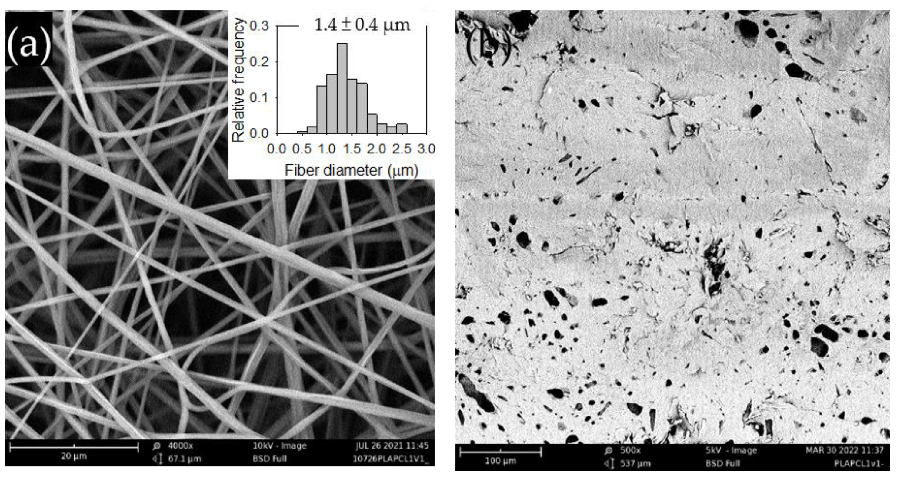
Figure 1a shows the SEM image of the electrospun PLA films along with its fiber diameter distribution.
Figure 1b presents the SEM image of the solvent-cast PLA films, which displayed a random but evenly distributed spindle-like structure. The structure may be attributed to phase-separated impurities present in the commercial PLA.
3.1.2. FTIR Analysis of the PLA Films
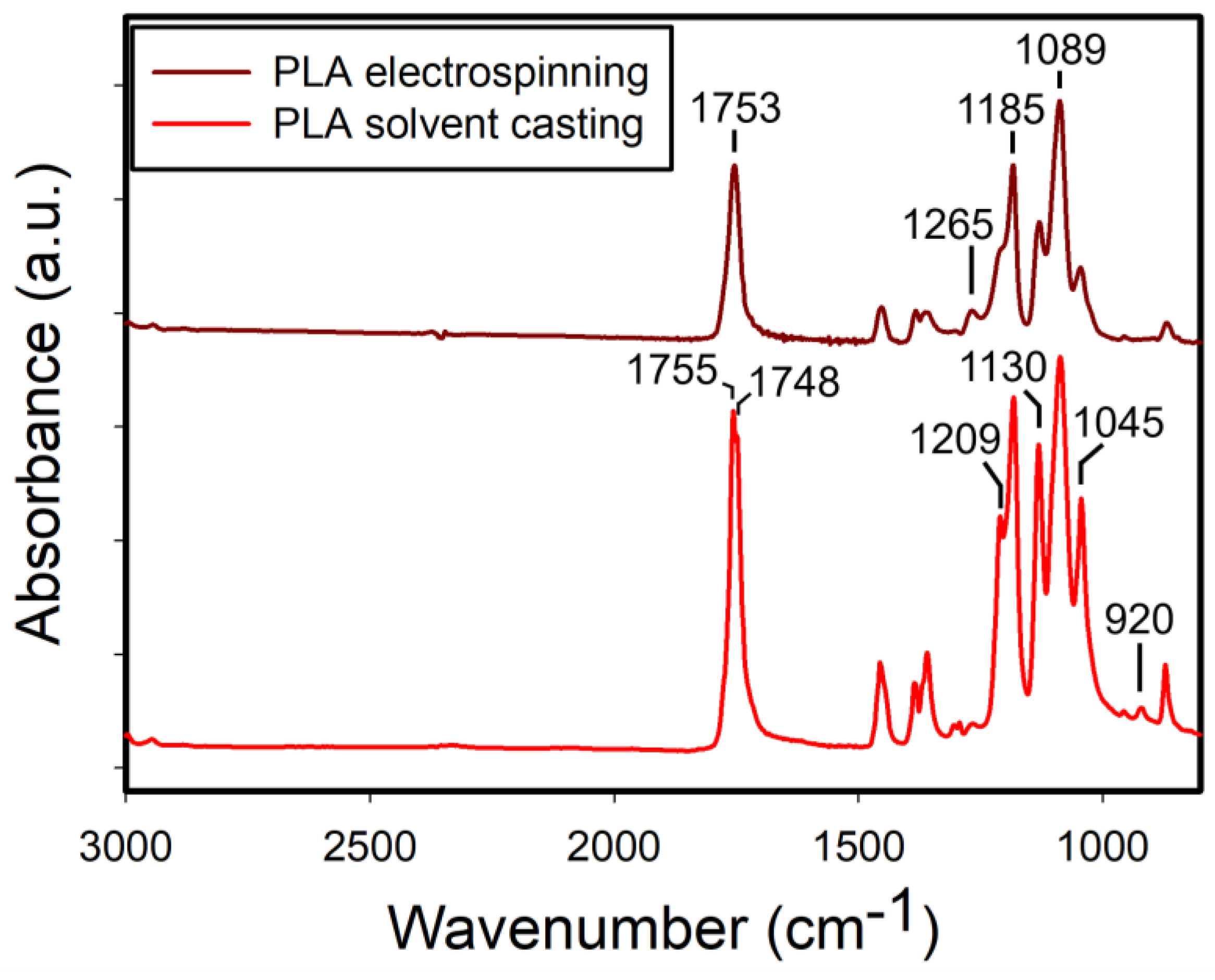
Figure 2 shows the FTIR spectra of both electrospun and solvent-cast PLA films. The solvent-cast films exhibited sharper and more intense absorption bands, indicating greater uniformity in bond angles and lengths, consistent with the more ordered packing of polymer chains characteristic of crystalline structures. Notably, the bands at 1045 cm
-1 (C-CH
3 stretching [
19,
20]) and 1130 cm
-1 (CH
3 rocking [
19,
20]) in the solvent-cast films were relatively more prominent than in the electrospun films, relative to the band at 1750 cm
-1 (C=O stretching) in each spectrum. In addition, the band at 920 cm
-1, associated with the backbone C-C vibration and CH
3 rocking [
19,
20], was observed only in the solvent-cast films. Previous studies have attributed the band at 920 cm
-1 to the PLLA crystal phases [
19,
21] and its absence in the electrospun films suggests their lack of the crystalline structures. Furthermore, an absorption band at 1265 cm
-1 was observed in the electrospun films, where it appeared relatively weak in the solvent-cast films. This band, along with the band at 1209 cm
-1 has been assigned to C-O-C stretching vibrations [
19,
20].
3.1.3. XRD Analysis of the PLA Films
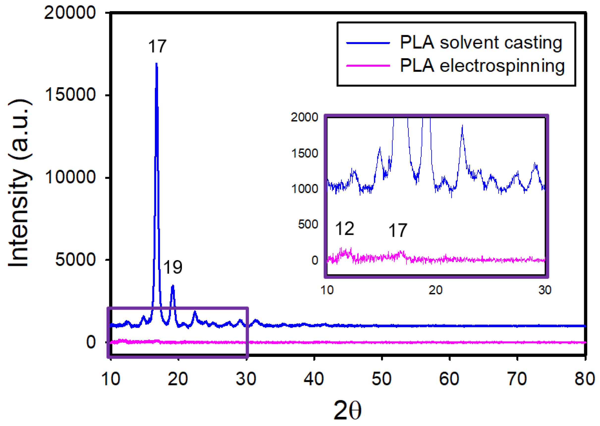
Figure 3 shows the X-ray diffraction (XRD) patterns of the electrospun and solvent-cast PLA films. The XRD pattern of the solvent-cast films exhibited intense diffraction peaks at 2θ = 17° and 19°. In contrast, the electrospun films showed almost no diffraction peaks, apart from two tiny protrusions at 2θ = 12° and 17°. The near absence of distinct diffraction peaks indicates small crystallite sizes or low crystallinity in the electrospun films.
3.1.4. Thermal Properties of the PLA Films
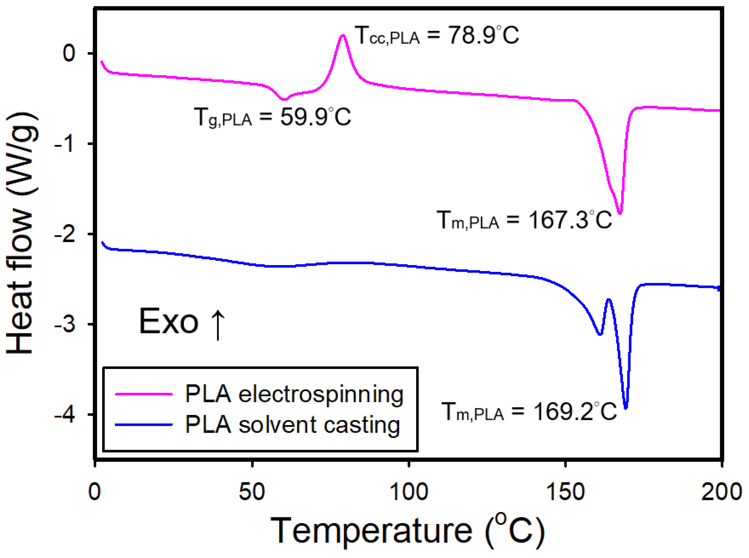
Figure 4 shows the DSC curves for the electrospun and solvent-cast PLA films. The electrospun PLA film exhibited a
Tg of approximately 59°C, a
Tcc of 78°C, and a
Tm of 167°C. On the other hand, the solvent-cast film displayed a broad endothermic band around 57°C, which was assigned as
Tg, and two endothermic peaks around 169°C with the absence of cold crystallization peak.
The DSC curve of the electrospun film exhibited a cold crystallization exotherm, indicating incomplete crystallization during the electrospinning process, with crystallization occurring upon heating above the glass transition temperature. The DSC curve of the solvent-cast film shows dual melting endothermic peaks, which might be caused by different crystalline structures or crystallite sizes of PLA, as reported in the literature [
22,
23,
24].
Table 1 presents the degrees of crystallinity of the electrospun and solvent-cast PLA films calculated from DSC curves by analyzing the melting and cold crystallization enthalpies. The electrospun PLA films had a significantly lower crystallinity degree than its solvent-cast counterpart. Bognitzki et al. reported that the degree of crystallinity (~35%) of electrospun PLA fibers is lower than that obtained for melt crystallization (60%) or crystallization from dilute solutions (90%). This was attributed to the rapid evaporation of solvent and dramatic increase in jet surface within milliseconds during electrospinning, which leaves minimal time for crystallization to occur [
25].
3.1.5. Mechanical Properties of the PLA Films
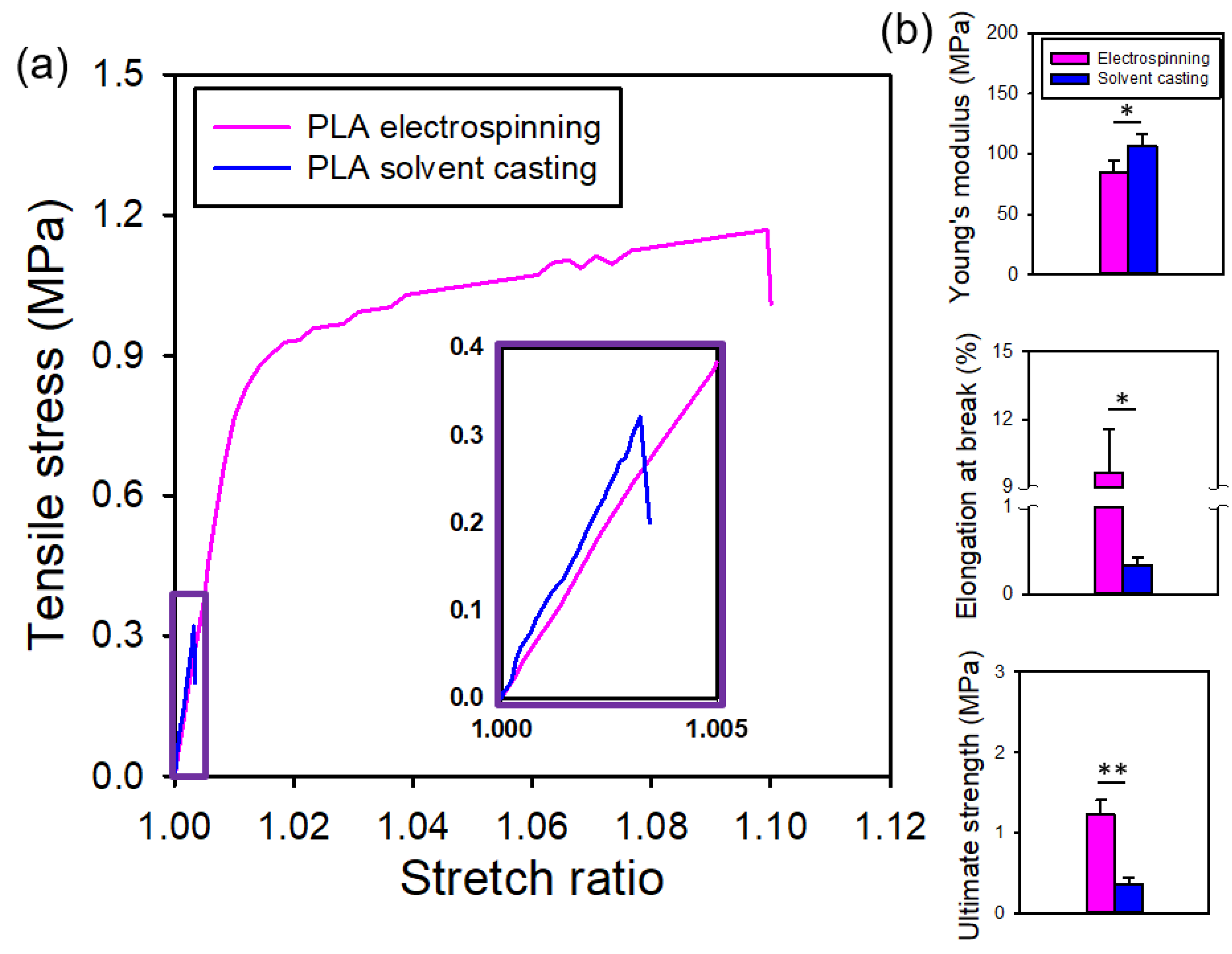
Figure 5a presents the representative stress-stretch curves for both types of PLA films., Notably, the electrospun PLA films exhibited clear yielding, with lower stiffness and greater toughness, in contrast to the brittle solvent-cast PLA films. That is, electrospun PLA films displayed better flexibility. The initial slope of the stress-stretch curves, which remained relatively constant within the stretch ratio range of 1.00 to 1.01, defines the Young’s modulus. The maximum stress observed in the stress-stretch curves defines the ultimate strength. The elongation at break is presented by the strain at which a sudden drop in stress occurs.
Figure 5b shows that the electrospun PLA films exhibited a lower Young’s modulus, greater elongation at break and higher ultimate strength compared to its solvent-cast counterpart. All these differences were statistically significant.
3.1.6. Water Contact Angle Measurements of the PLA Films
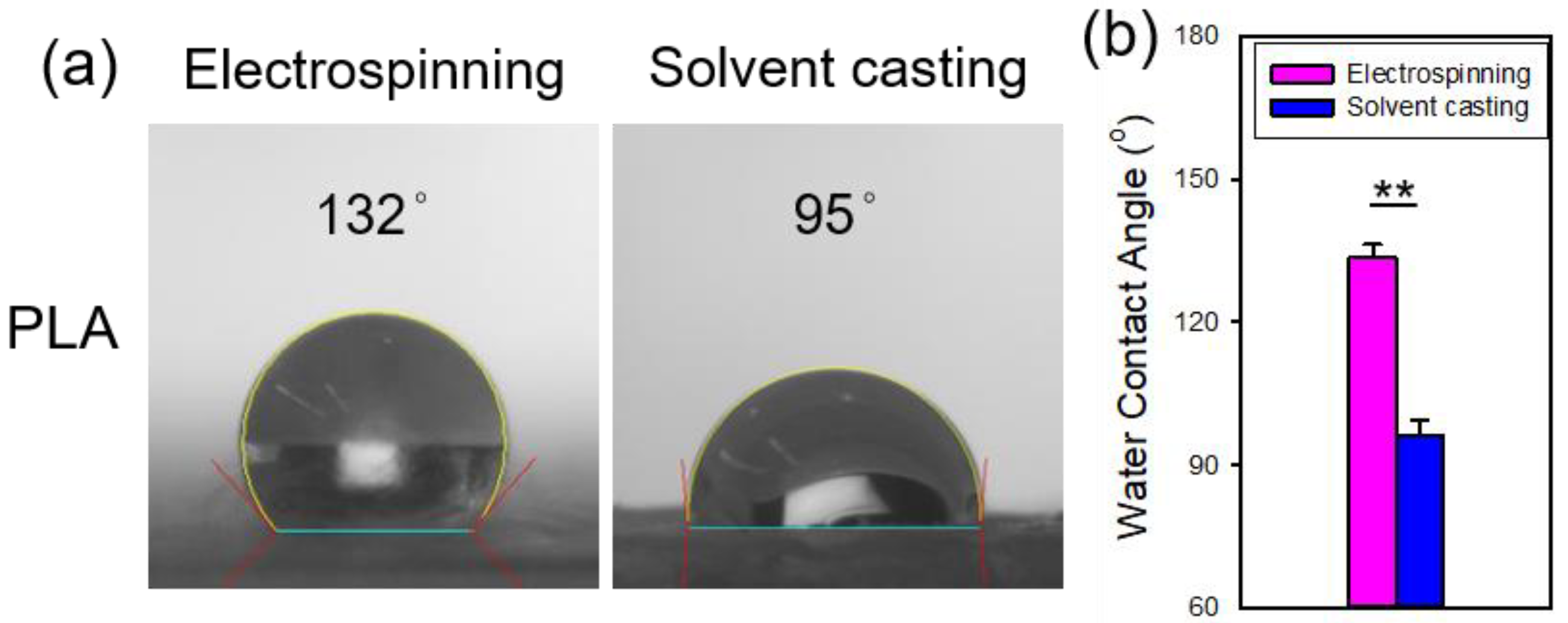
Figure 6 shows the water contact angles of the electrospun and solvent-cast PLA films. The contact angle for the electrospun PLA films was significantly higher than that of the solvent-cast PLA films, indicating greater hydrophobicity in the electrospun PLA. This can be explained by the Cassie-Baxter model, which suggests that the rougher surface of electrospun film traps more air pockets, leading to enhanced hydrophobicity and a higher contact angle [
26].
3.1.6. AFM Characterization of Single Fiber Morphology
AFM phase imaging can detect variations in mechanical or viscoelastic properties on the fiber surface, thereby providing insights into the nanoscale morphology and material heterogeneity of the fiber.
Figure 7 shows AFM images of a single electrospun PLA fiber. The leftmost amplitude image showed the overall fiber morphology, scanned over an area of 10 μm × 10 μm. The next two images are enlarged amplitude and phase images of the same region, with a scan area of 3 μm × 3 μm. The phase images revealed the crystalline structure on the fiber surface. A further magnification of the phase image, with a scan area of 1 μm × 1 μm, clearly showed that the crystalline structure of PLA aligned parallel to the fiber direction. This aligned crystalline structure may explain the preserved stiffness of electrospun PLA films, which also exhibited higher elongation at break and ultimate strength. Lim et al. demonstrated that PCL electrospun fibers with aligned crystalline structures exhibited higher Young's modulus and strength [
27]. Similarly, Goonoo et al. reported comparable trends in in electrospun fibers from polymer blends [
28].
3.2. PLA/PCL Blends
3.2.1. Surface Morphology of the Films of PLA/PCL Blends
Figure 8a and
Figure S1a show the SEM micrographs of the electrospun PLA/PCL blends at 1:1 and 1:2 ratios, respectively. As the PCL content increased, a slight increase in fiber diameter was observed
Figure 8b and
Figure S1b illustrate the surface morphology of the corresponding solvent-cast films, where significant surface heterogeneity and irregular pores were evident. The appearance of irregular pores is likely attributed to solvent evaporation process. The choice of solvent plays a critical role in determining pore size and morphology, as previously reported by Sun et al., who demonstrated that solvents with higher boiling point tend to produce smaller pores [
29].
Electrospun and solvent-cast PCL films were succssfully prepared using similar conditions;
Figure S2 presents their SEM images. The fiber diameter of electrospun PCL was significantly larger than that of the PLA/PCL blends. The surface of the solvent-cast PCL films appeared smoother than that of its PLA blends counterpart, with small pores observed.
3.2.2. FTIR Analysis of the Films of PLA/PCL Blends
The FTIR spectra of the electrospun and solvent-cast PCL films are shown in
Figure S3. Unlike PLA, the spectral features including intensity of the two film types were largely similar, with the exception of the carbonyl stretching at 1720 cm
-1, which was more intense in the solvent-cast films. In addition, the composite band in the region of 1162-1186 cm
-1, exhibited slight sifts in peak position between the two film types. The characteristic absorption bands of PCL were identified at 2940 cm
-1 (asymmetric stretching of CH
2), 1720 cm
-1 (C=O stretching), 1240 cm
-1 (asymmetric stretching of C-O), and 1180 cm
-1 (symmetric stretching of C-O), in agreement with a previous report [
30].
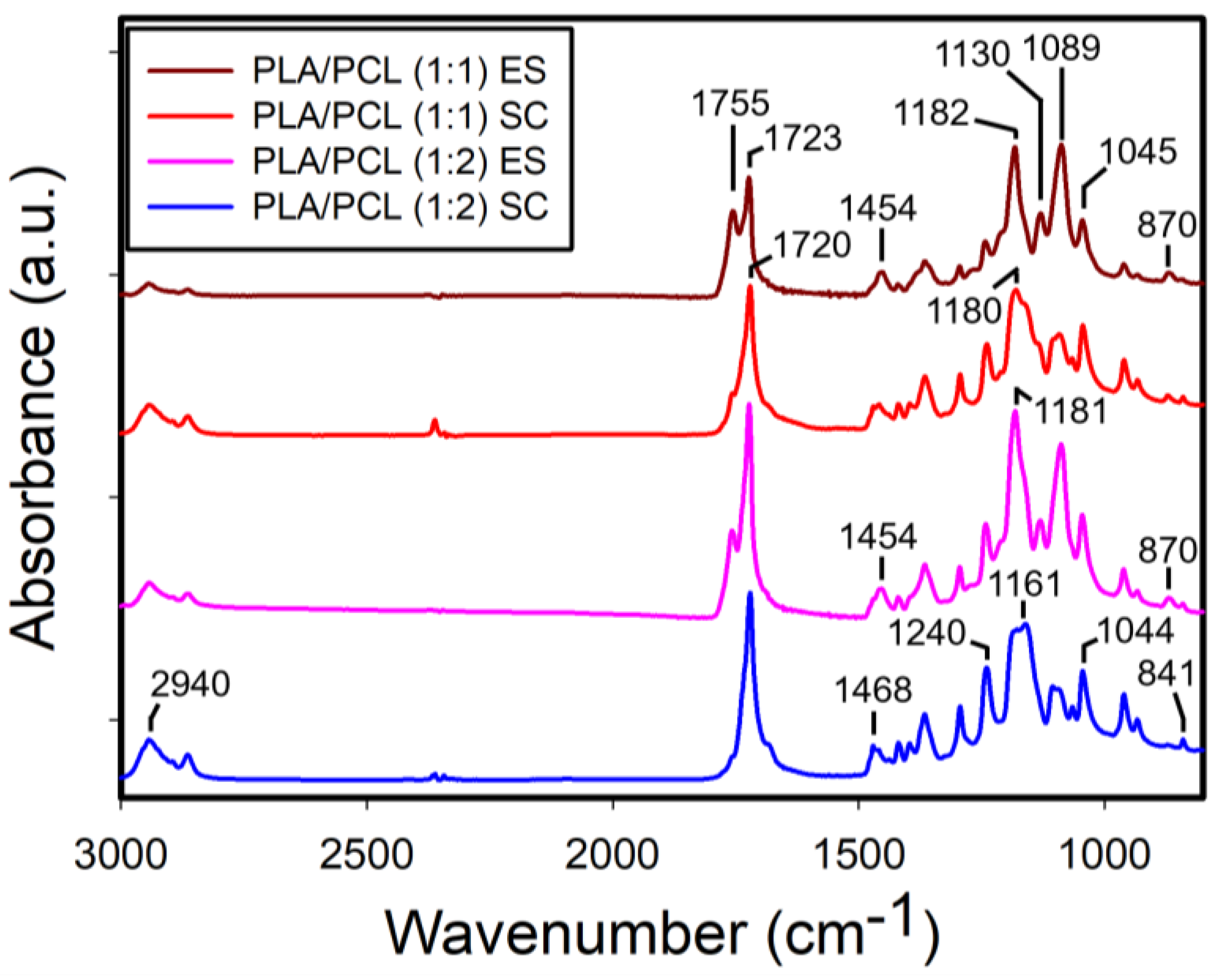
Figure 9 displays the FTIR spectra of the electrospun and solvent-cast PLA/PCL blends at 1:1 and 1:2 ratios. Notably, in the electrospun films, the characteristic absorption bands of PLA were more pronounced for both blend ratios. In contrast, the intensity of PLA absorption bands decreased in the solvent-cast films with a further reduction observed as the PCL content increased.
3.2.3. XRD Analysis of the Films of PLA/PCL Blends
Figure S5 shows the XRD patterns of both electrospun and solvent-cast PCL films. The solvent-cast PCL films exhibited prominent diffraction peaks at 2θ = 21° and 24°, characteristic of the crystalline phase of PCL. In contrast, the electrospun PCL films displayed significantly reduced peak intensities at these same positions, indicating a lower degree of crystallinity. Notably, the characteristic peaks remained detectable in the electrospun PCL films, whereas those of crystalline PLA were barely detectable in the XRD patterns of the electrospun PLA films.
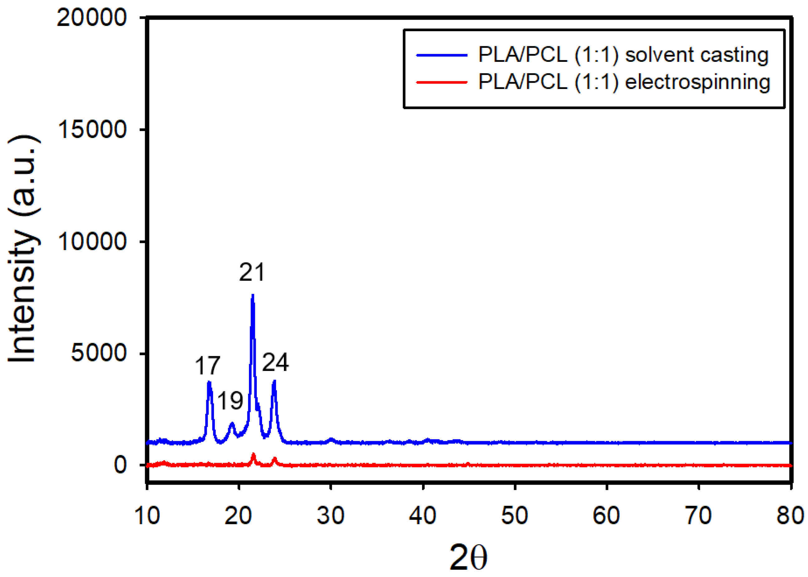
Figure 10 and
Figure S6 present the XRD patterns of both electrospun and solvent-cast films of PLA/PCL blends with ratios of 1:1 and 1:2, respectively. In the solvent-cast films, distinct diffraction peaks corresponding to PLA were observed at 2θ = 17° and 19°, and those for PCL appeared at 2θ = 21° and 24°, indicating the co-existence of PLA-rich and PCL-rich phases in the blends. There were no apparent shifts in characteristic peaks of PLA for the two ratios, suggesting that PCL has no significant effect on the crystal structure of PLA. In contrast, the electrospun films displayed only weak PCL peaks, with the PLA peaks no longer detectable.
3.2.4. Thermal Properties of the Films of PLA/PCL Blends
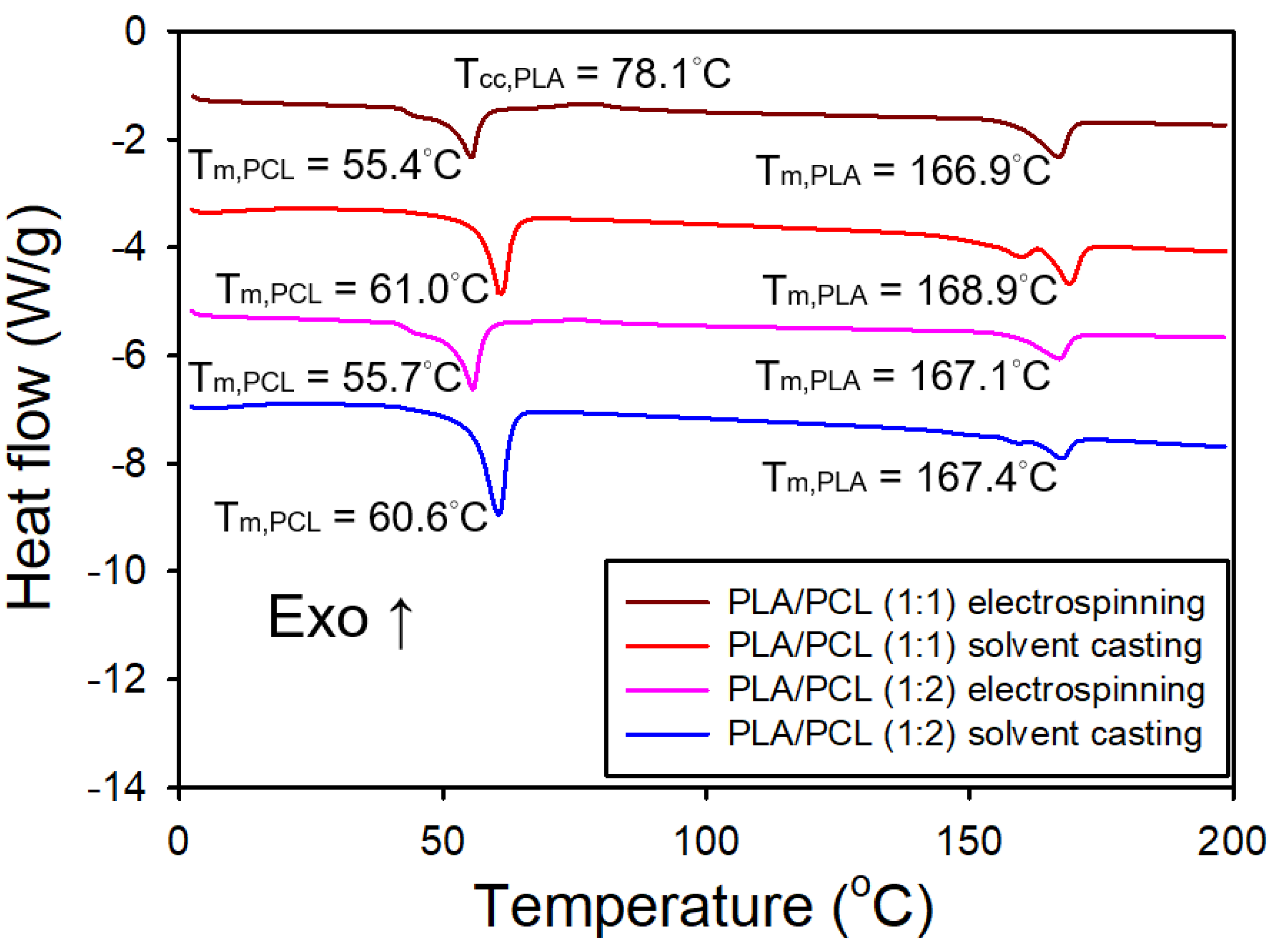
Figure 11 shows the DSC thermograms of both electrospun and solvent-cast films of PLA/PCL blends (1:1 and 1:2). The immiscibility of PLA and PCL was confirmed by the DSC curves of the blends, which exhibited two distinct melting peaks corresponding to PLA and PCL, consistent with a previous report [
31]. For the electrospun films, the DSC curves revealed an endothermic peak at around 55°C, corresponding to the melting of PCL, an exothermic peak at around 78°C, indicative of the cold crystallization of PLA, and an endothermic peak near 167°C, corresponding to the melting of PLA. The intensity of the exothermic peak associated with PLA cold crystallization diminished as the PLA content decreased. In contrast, the DSC curves for the solvent-cast films showed an endothermic peak at about 60°C, corresponding to the melting of PCL, along with dual endothermic peaks at around 169°C, which are attributed to the melting of PLA. Notably, the exothermic peak from PLA cold crystallization was absent in the solvent-cast films. The melting temperature of PCL was higher in the solvent-cast films compared to the electrospun films, likely due to increased crystallinity in the former. A similar trend was noted for PLA, although the difference in melting temperatures between the two processing methods was less pronounced.
Table 2 presents the crystallinity of both electrospun and solvent-cast films of neat PLA, PLA/PCL (1:1), PLA/PCL (1:2), and neat PCL. The electrospun films of PLA/PCL blends exhibited a significantly lower crystallinity degree of PLA compared to their solvent-cast counterparts. Furthermore, the crystallinity degree of PLA in the electrospun films increased markedly with increasing PCL content. In contrast, the crystallinity degree of PLA in the solvent-cast films slightly decreased as the PCL content increased. The crystallinity degree of PCL, however, slightly decreased in the presence of PLA for both film types.
3.2.5. Mechanical Properties of the Films of PLA/PCL Blends
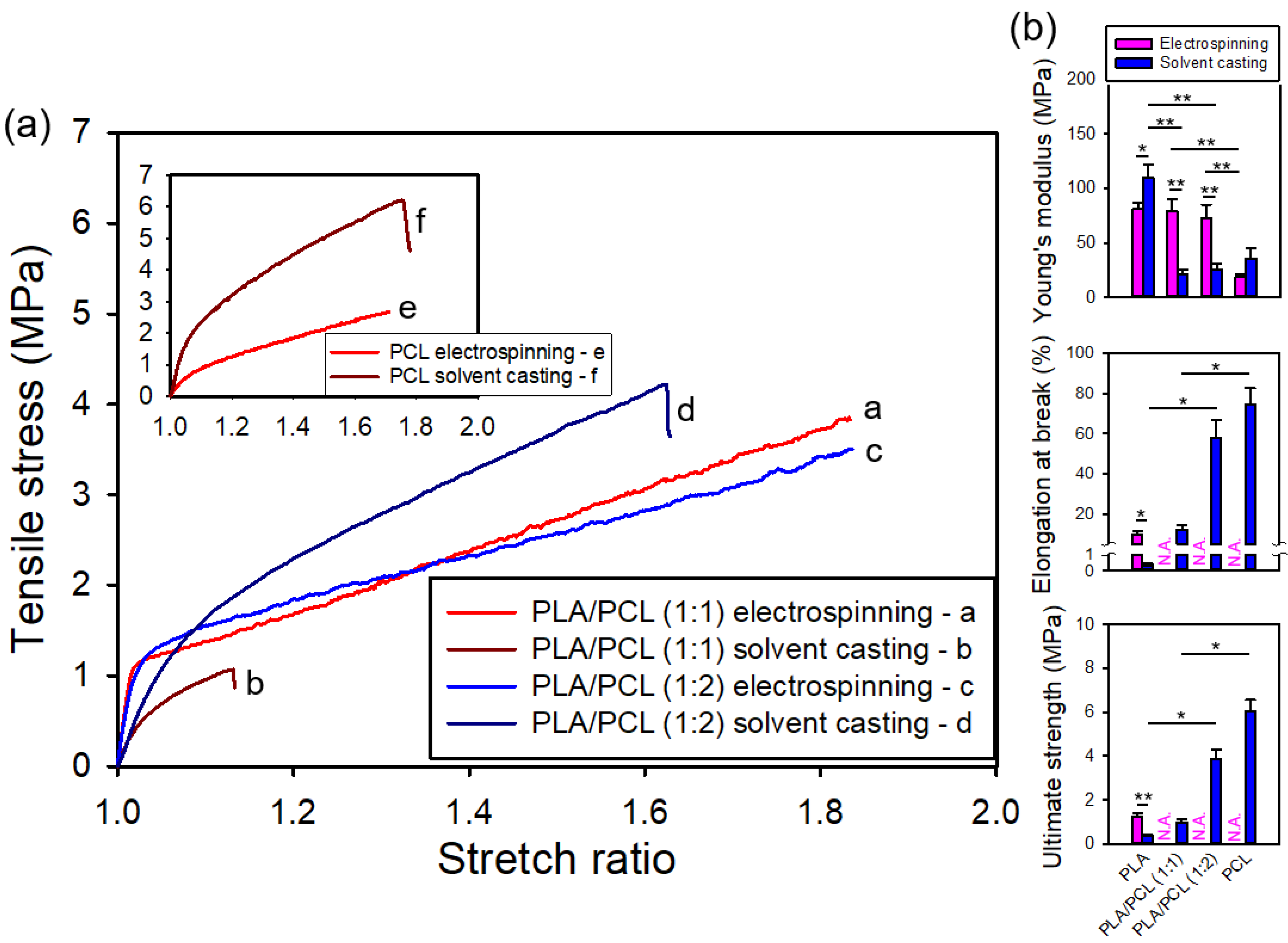
Figure 12a shows the representative stress-stretch curves for both electrospun and solvent-cast films of PLA/PCL blends (1:1 and 1:2) and neat PCL. All films, whether prepared by electrospinning or solvent-casting, exhibited clear yielding. For the electrospun films, the specimens, originally in sheet form, transformed into a bundle when the stretch ratio reached approximately 1.8, causing the surface markers to detach and preventing the estimation of elongation at break and hence ultimate strength.
Figure 12b provides statistical comparisons of the mechanical properties of both electrospun and solvent-cast films of neat PLA, PCL, and PLA/PCL blends (1:1 and 1:2). Among the solvent-cast films, neat PLA exhibited the highest Young's modulus, but this value significantly decreased with the addition of PCL, which has a lower modulus. However, the Young's modulus, ultimate strength, and elongation at break all showed varying degrees of enhancement with increasing PCL content.
Interestingly, for the electrospun films, no significant difference in Young's modulus was observed among neat PLA and the PLA/PCL blends (1:1 and 1:2), indicating that the stiffness of electrospun PLA films was not notably reduced by the addition of PCL — unlike the behavior observed in solvent-cast films. Unfortunately, due to the detachment of tracking markers, the elongation at break and ultimate strength of neat PCL and the PLA/PCL blends could not be determined. Nevertheless, the elongation at break for these films appeared to be considerably greater than that of neat PLA.
Considering PLA/PCL blends, the Young's modulus of electrospun films was significantly higher than that of solvent-cast films, in contrast to neat PLA and PCL. Polymer miscibility strongly affects the mechanical properties of solvent-cast films from polymer blends. PLA and PCL were shown to be poorly miscible polymers [
32,
33,
34]. Their poor miscibility likely leads to the significantly lower Young's modulus in solvent-cast films. This observation is consistent with findings by Chen et al. [
32], Murphy et al. [
35], and Wei et at. [
36], who reported that poor miscibility and weak interfacial adhesion between PLA and PCL reduces stiffness and strength in solvent-cast films. In contrast, this effect was not observed in electrospun films, likely due to the rapid solvent evaporation during electrospinning, which suppresses phase separation and minimizes the impact of poor miscibility. In addition, the electrospun films demonstrated a much greater elongation at break, presumably exceeding 80%, compared to their solvent-cast counterparts.
3.2.6. Water Contact Angle Measurement of the Films of PLA/PCL Blends
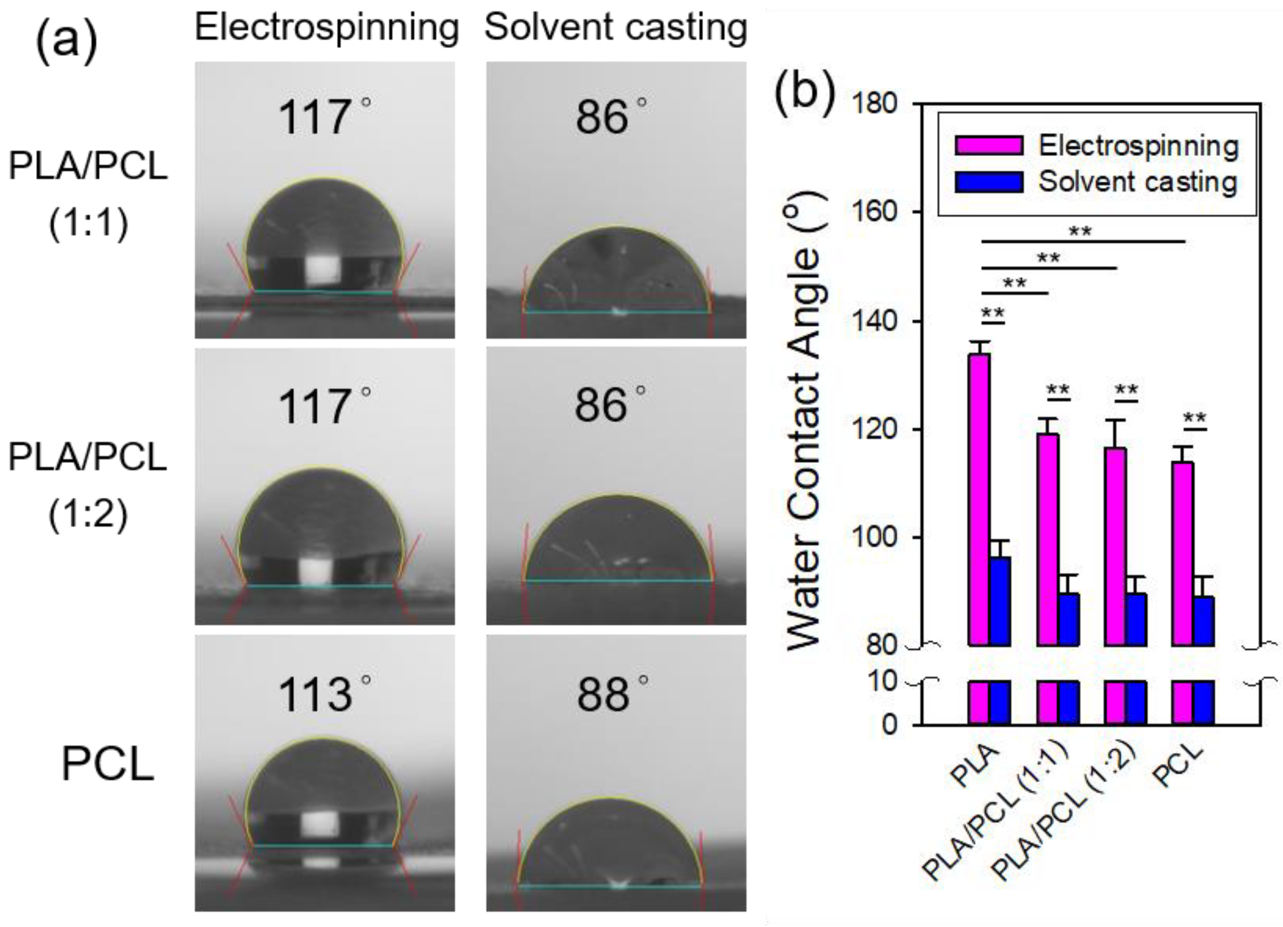
Figure 13 shows the contact angle measurements of the electrospun and solvent-cast films of PLA/PCL blends (1:1 and 1:2) and neat PCL along with their statistical comparisons, including neat PLA for reference. For both processing methods, the contact angles of the PLA/PCL bends were closer to those of neat PCL, with a more pronounced deviation from neat PLA observed in the electrospun films. However, no significant differences in contact angles were found among the solvent-cast films across the four groups. Consistent with previous observations for neat PLA, the electrospun films exhibited larger contact angles compared to their solvent-cast counterparts for both PLA/PCL blends and neat PCL, indicating greater hydrophobicity in the electrospun films. This phenomenon can be explained by the Cassie-Baxter model, as was noted for neat PLA. Note that the ATR-FTIR spectra of electrospun films revealed more pronounced characteristic absorption bands of PLA, which is more hydrophobic than PCL, for both blend ratios. This suggests that PLA is more concentrated at the electrospun fiber surface. Deng suggested that the surface hydrophobicity of electrospun and solvent-cast films is influenced by different mechanisms [
37]. During electrospinning, the hydrophobic groups of the polymer reorient toward the relatively nonpolar air-facing surface, resulting in a hydrophobic surface. In contrast, during the solvent-casting, the rapid evaporation of more volatile solvents increases the overall solvent polarity, leaving behind less volatile solvents [
37]. Farrugia and Groves reported that the increase in the solvent polarity favors the formation of hydrogen bonds [
38], which can result in a more hydrophilic fiber surface with a higher concentration of polar groups.
3.2.7. AFM Characterization of Single Fiber Morphology
Figure 14 shows the AFM images of an electrospun fiber from a 1:1 blend of PLA and PCL. The leftmost amplitude image depicted the fiber morphology. The next two images were enlarged amplitude and phase images of the same region. In the further magnified phase image, irregular, island-like domains were observed, which could be attributed to phase separated regions or crystalline structures.
Figure S6 shows the AFM images of a single electrospun PCL fiber, in which fiber-like structures were observed in the phase image, which likely are crystalline structures. In contrast to the morphology shown in the phase images of a single PLA fiber (
Figure 7), these structures were aligned more perpendicularly to the fiber direction.
3.3. PLA/PEO Blends
3.3.1. Surface Morphology of the Films of PLA/PEO Blends
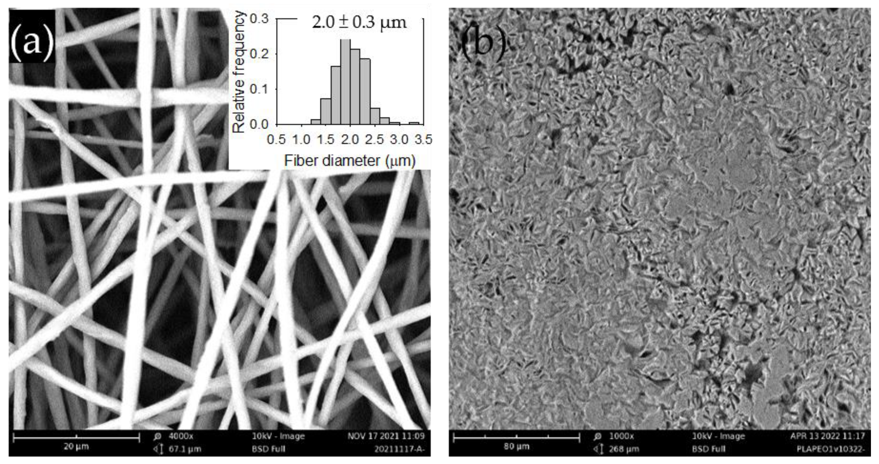
Figure 15a and
Figure S9a show the SEM images of the electrospun PLA/PEO blends at two ratios, 1:1 and 1:2, respectively. The fiber diameter distributions were similar for both ratios.
Figure 15b and
Figure S9b show the surface morphology of the solvent-cast counterparts. The co-continuous morphology observed in the solvent-cast films indicates phase separation, which becomes more pronounced with increasing PEO content.
3.3.2. FTIR Analysis of the Films of PLA/PEO Blends
The FTIR spectrum of the solvent-cast PEO films is shown in
Figure S4. Note that we were unable to fabricate electrospun PEO films using the DCM/DMF solvent system. The characteristic absorption bands of PEO were observed at 2880 cm
-1 (CH
2 stretching), 1468 cm
-1 (CH
2 scissoring), 1340 cm
-1 (CH
2 wagging), 1100 cm
-1 (C-O-C stretching), and 960 cm
-1 (CH
2 symmetric rocking), consistent with a previous report [
39].
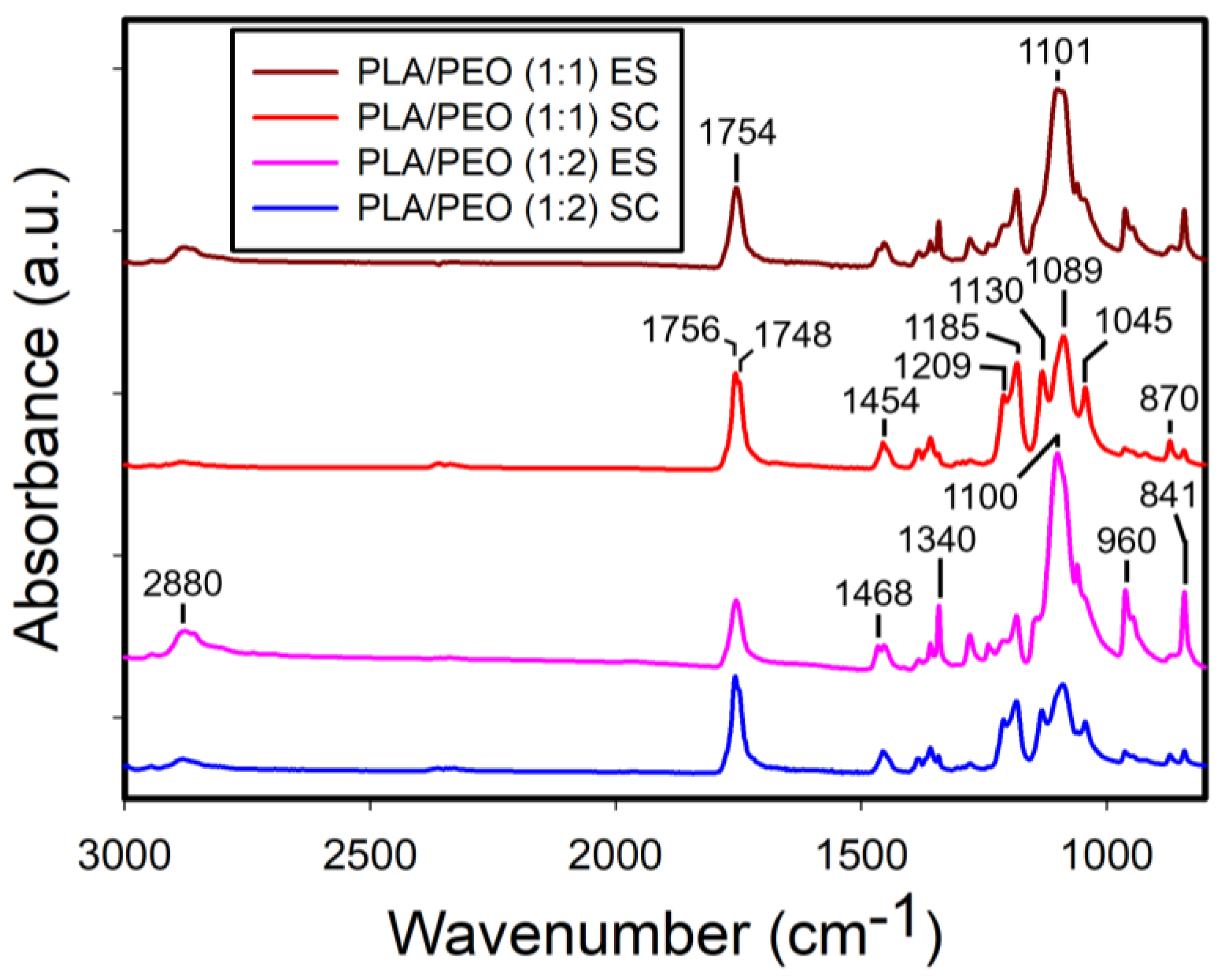
Figure 16 shows the FTIR spectra of the electrospun and solvent-cast PLA/PEO blends at 1:1 and 1:2 ratios. Interestingly, unlike the PLA/PCL blends, the characteristic absorption bands of PLA exhibited reduced intensity in the electrospun films, while they were more prominent in the solvent-cast films for both blend ratios.
3.3.3. XRD Analysis of the Films of PLA/PEO Blends
While electrospun PEO films were not available, the XRD pattern of the solvent-cast PEO films is shown in
Figure S9, displaying characteristic diffraction peaks at 2θ = 19° and 23°, typical of PEO.
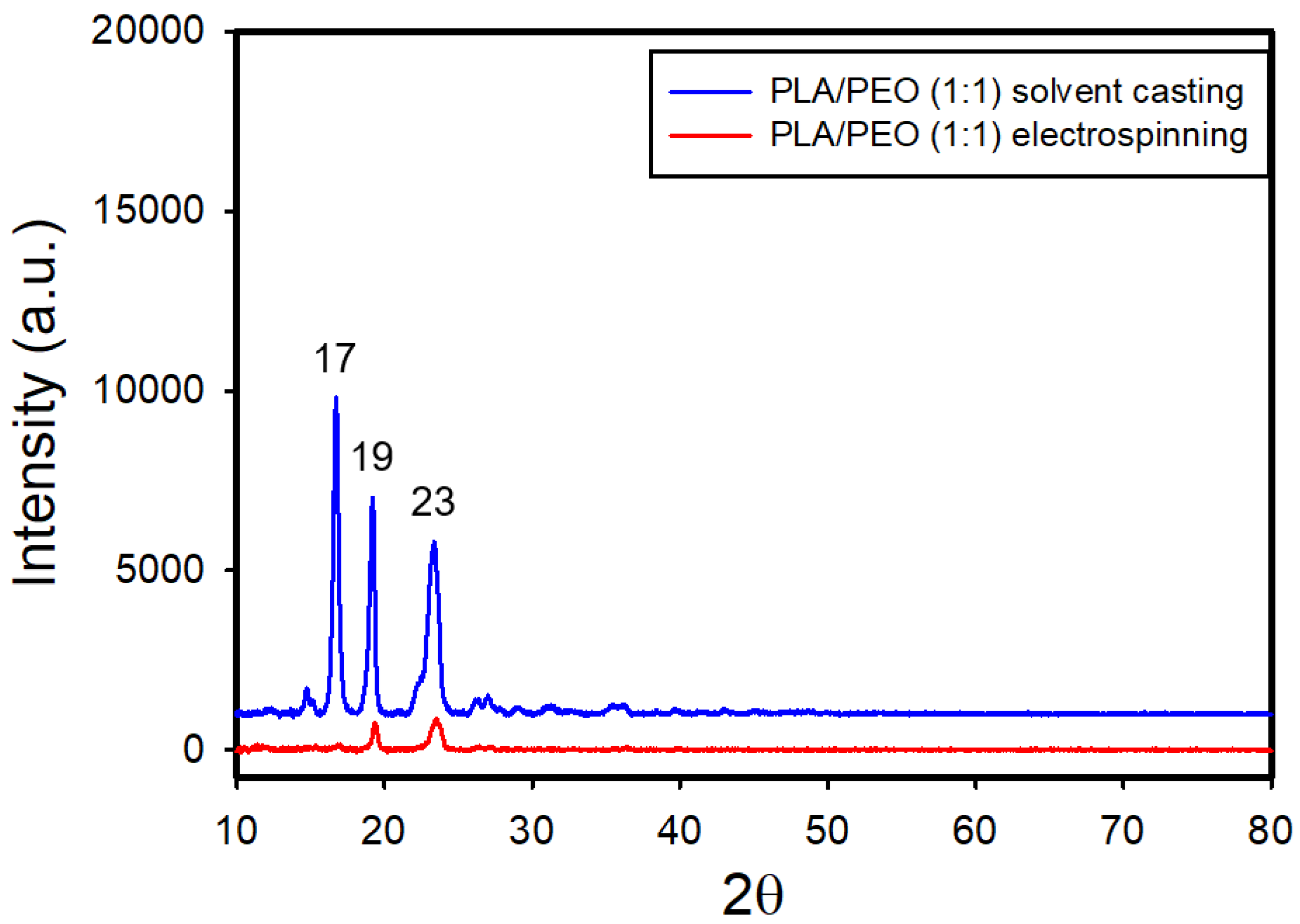
Figure 17 and
Figure S10 show the XRD patterns of both electrospun and solvent-cast PLA/PEO blend films with ratios of 1:1 and 1:2, respectively. In the solvent-cast films, the diffraction peak at 19° appeared to result from contributions of both PEO (with peaks at 2θ = 19° and 23°) and PLA (with peaks at 2θ = 17° and 19°); the peak at 2θ = 19° was more intense than that at 2θ = 23°. However, in the electrospun films, only the diffraction peaks of PEO were detected, with the PLA peaks substantially diminished.
3.3.4. Thermal Properties of the Films of PLA/PEO Blends
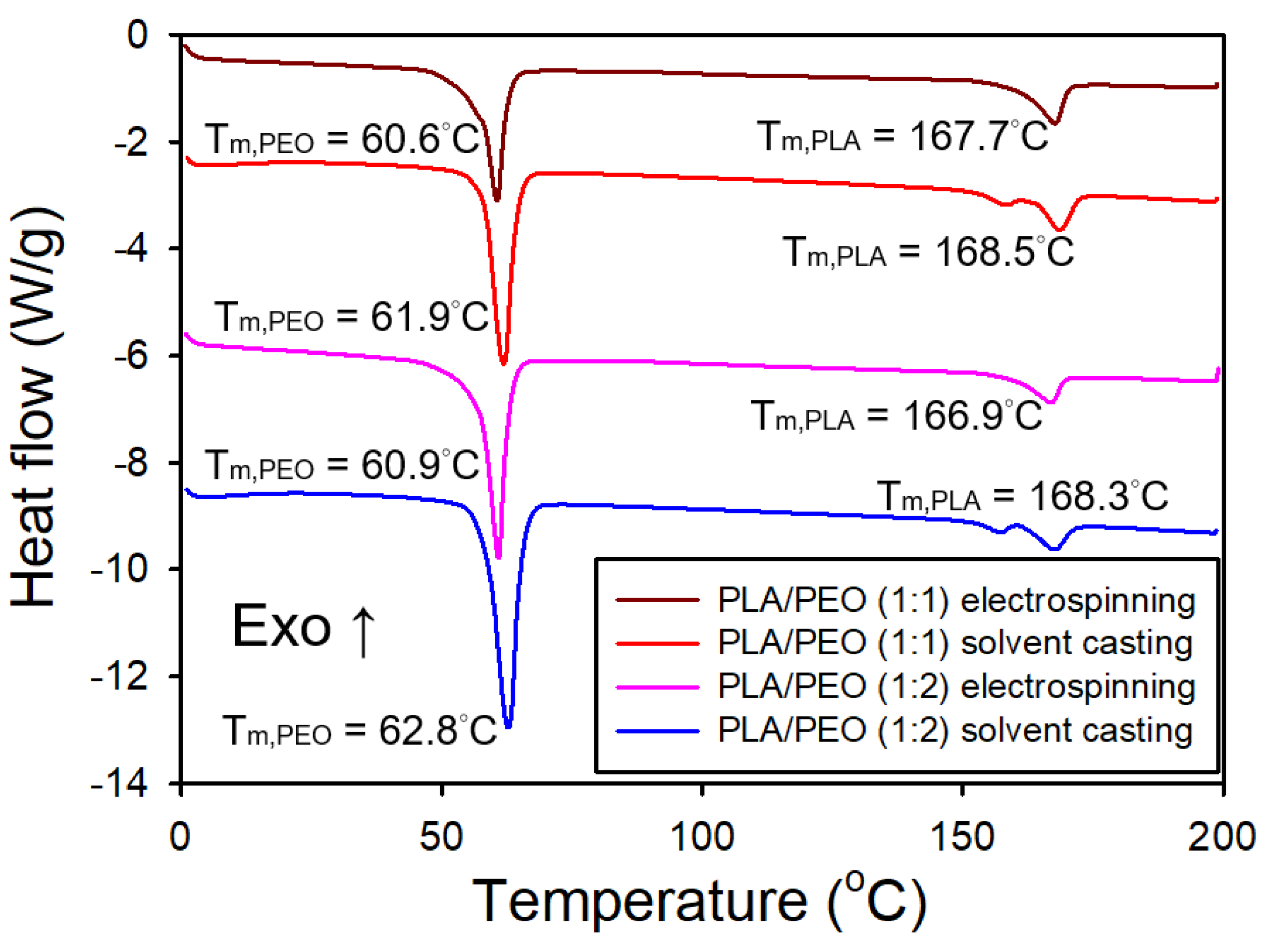
Figure 18 shows the DSC thermograms of both electrospun and solvent-cast films of PLA/PEO blends (1:1 and 1:2). For the electrospun films, an endothermic peak at approximately 61°C was observed, corresponding to the melting of PEO, along with an endothermic peak at about 167°C, corresponding to the melting of PLA. In the solvent-cast films, an endothermic peak at approximately 62°C and dual endothermic peaks at around 169°C were detected, corresponding to the melting of PEO and PLA, respectively. Notably, the melting temperature of PEO in the solvent-cast films was slightly higher than in the electrospun films, likely due to the increased crystallinity of the solvent-cast films. This trend is also observed for neat PLA in both types of films.
Table 3 presents the crystallinity of both electrospun and solvent-cast films of neat PLA, PLA/PEO blends (1:1 and 1:2), and neat PEO. The electrospun films of PLA/PEO blends exhibited a significantly lower crystallinity degree of PLA compared to their solvent-cast counterparts. Furthermore, the crystallinity degree of PLA in the electrospun films increased markedly with the addition of PEO. In contrast, the crystallinity degree of PLA in the solvent-cast films slightly decreased as the PEO content increased. However, the crystallinity degree of PEO slightly decreased in the presence of PLA in the electrospun films.
3.3.5. Mechanical Properties of the Films of PLA/PEO Blends
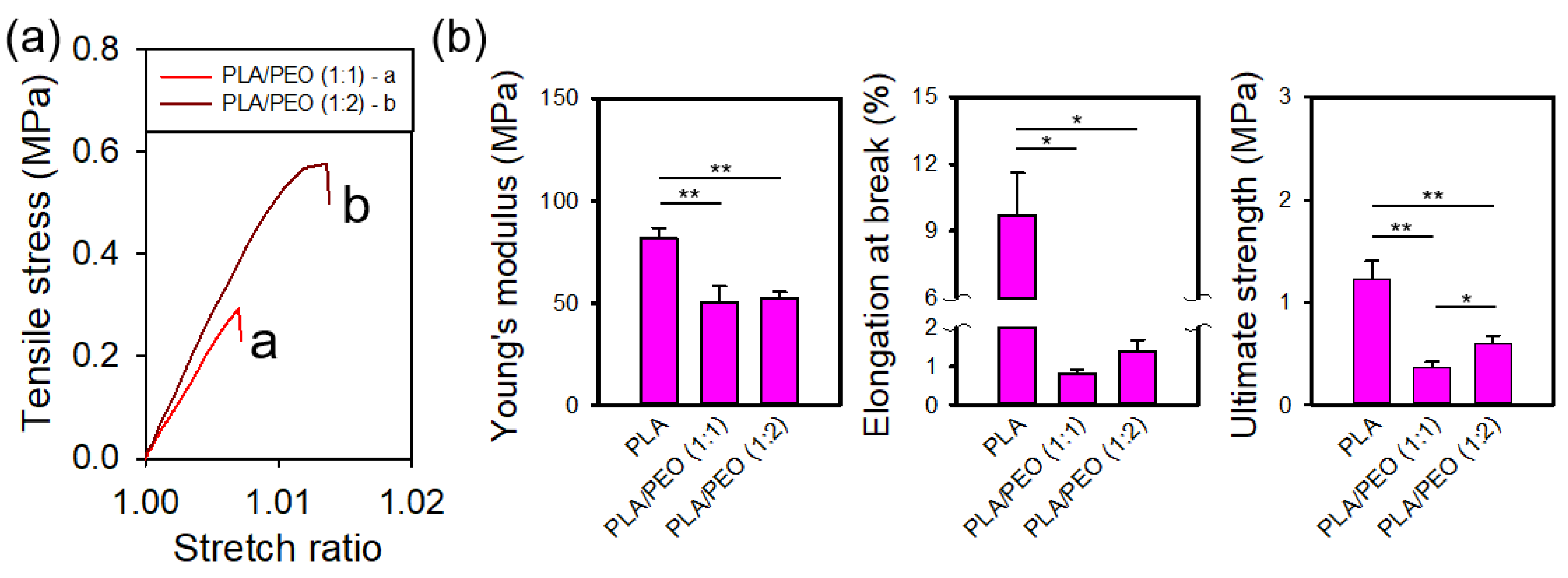
Because of the extreme brittleness of the solvent-cast films from PLA/PEO blends (1:1 and 1:2), intact testing specimens could not be obtained through die cutting.
Figure 19a shows the representative stress-stretch curves for electrospun films of PLA/PEO blends (1:1 and 1:2).
Figure 19b presents statistical comparisons of the mechanical properties of electrospun films of neat PLA and the PLA/PEO blends (1:1 and 1:2). The Young's modulus of the PLA/PEO blends was significantly lower than that of neat PLA. In addition, both the elongation at break and ultimate strength exhibited a substantial decrease with the addition of PEO. No statistical differences were observed in Young’s modulus or elongation at break between the 1:1 and 1:2 blends; however, the ultimate strength of the 1:2 blend was significantly greater than that of 1:1 blend.
3.3.6. Water Contact Angle Measurement of the Films of PLA/PEO Blends
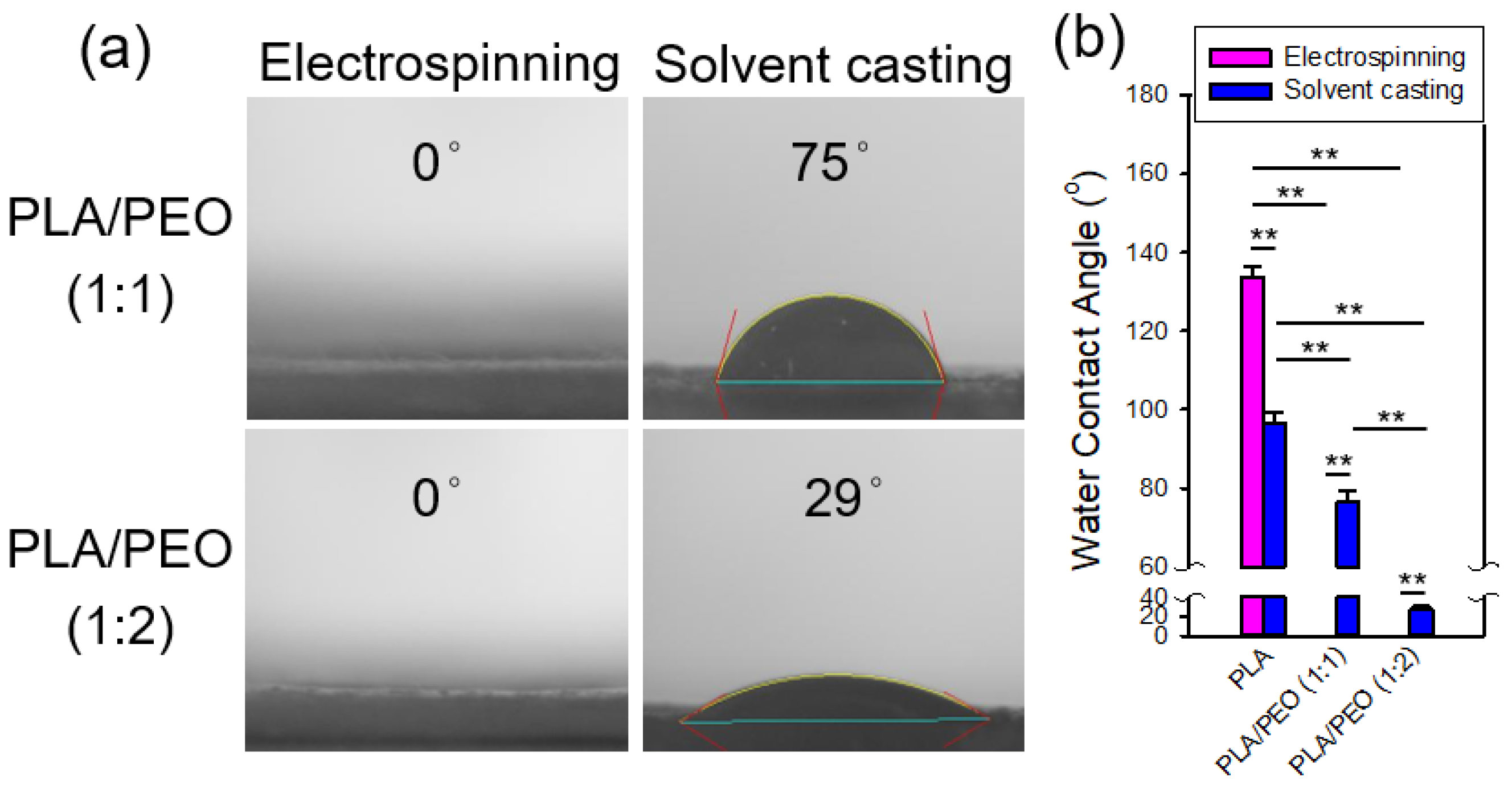
Figure 20 shows the contact angle measurements of the electrospun and solvent-cast films of PLA/PEO blends (1:1 and 1:2) along with statistical comparisons to neat PLA. The addition of PEO markedly enhanced the hydrophilicity of both electrospun and solvent-cast films. The contact angles of the solvent-cast PLA/PEO films were significantly smaller than those of the solvent-cast PLA films, with further reductions as the PEO content increased. On the other hand, for both electrospun PLA/PEO blends, the contact angles were 0°, significantly lower than those of the electrospun PLA films. In fact, water droplets were immediately adsorbed upon contact with the electrospun PLA/PEO films. This behavior is likely due to the combined effects of the hydrophilic nature of PEO and the porous structure of the electrospun fibers. The wettability of solid surfaces depends on both their chemical composition and surface morphology [
40]. Natu et al found that PCL/Lu (Lu stands for Lutrol F127, a hydrophilic copolymer) blend fibers were highly hydrophilic, with water contact angle below 20°. They attributed this hydrophilicity to the preferential arrangement of Lu at the fiber surface [
41]. Note that the ATR-FTIR spectra of electrospun films revealed more pronounced characteristic absorption bands of PEO, which is more hydrophilic than PLA, for both blend ratios, indicating that PEO is more prevalent at the surface of the electrospun fibers.
3.3.7. AFM characterization of single fiber morphology
Figure 21 shows the AFM images of an electrospun fiber from a 1:1 blend of PLA and PEO. The phase images on the right reveal pebble-like domains on the fiber surface, likely correspond to phase-separated regions or crystalline domains. The higher-magnification image provides a more detailed view of these domains, which appear to be slightly aligned along the fiber direction.
3.4 Limitations and Future Perspectives
In this study, we used a mixture of DCM and DMF to dissolve neat PLA, PCL and PEO, as well as PLA/PCL and PLA/PEO blends, for the preparation of both electrospun and solvent-cast films. This solvent mixture has proven effective for electrospinning [
42] and we have successfully used it to fabricate electrospun PLA or PCL films with satisfactory results [
43,
44]. The rapid fiber solidification during electrospinning hardly allows sufficient time for complete phase separation of the PLA blends. During solvent casting, however, the slower evaporation of the solvents allows the distinct volatilities of DCM and DMF to more significantly affect the phase separation dynamics of the PLA blends. In addition, the different solubility of PLA, PCL and PEO in DCM and DMF may further complicate phase separation during film formation, potentially leading to irregular morphology due to uneven solvent evaporation. The solvent-cast films may be better prepared using a single, low volatile solvent to avoid the complications.
Byun et al. found that the crystallinity of solvent-cast PLA films was influenced by the solvent system used, with higher boiling point solvents leading to more crystalline, but also more brittle, films [
12]. Given that solvent systems play a crucial role in polymer crystallization and have been shown to affect fiber morphology [
45], it may be worth investigating a broader range of solvent systems for electrospinning.
This study provides a basic understanding of how electrospinning can affect the mechanical properties of neat PLA and its blends with PCL and PEO. Future research will focus on optimizing the compositions of blends and processing parameters to further enhance the mechanical properties of the PLA-based films. Additionally, exploring the biocompatibility and degradation behavior of these films in vitro and in vivo is crucial for their biomedical applications.
5. Conclusions
This study has demonstrated that the choice of processing method – electrospinning versus solvent casting – has a substantial influence on the mechanical properties of films made from neat PLA, PLA/PCL blends, and PLA/PEO blends. Electrospun films consistently displayed superior flexibility compared to their solvent-cast counterparts, a result largely attributed to the distinct fibrous structure and low crystallinity of electrospun films. In the case of neat PLA, electrospinning produced more ductile films, characterized by slightly higher elongation at break and ultimate strength, while maintaining stiffness comparable to the solvent-cast PLA. For PLA/PCL blends, electrospinning significantly improved the elongation at break, without compromising stiffness observed in the solvent-cast films. These mechanical enhancements can be attributed to the reduced crystallinity and the alignment of crystalline domains in the electrospun fibers. However, the incorporation of PEO into PLA, while effectively in increasing surface hydrophilicity, resulted in marked reduction in mechanical performance. This highlights a trade-off between mechanical performance and improved hydrophilicity, potentially limiting the suitability of PLA/PEO blends in applications where mechanical integrity is crucial.
The electrospun films of neat PLA, PCL and PLA/PCL blends exhibited higher surface hydrophobicity compared to their solvent-cast counterparts. In contrast, both the electrospun and solvent-cast films of PLA/PEO blends displayed significant enhanced surface hydrophilicity compared to neat PLA.
Overall, the findings of this study indicate that electrospinning is a promising processing method for enhancing the mechanical properties of PLA-based films, particularly in cases where flexibility and mechanical integrity are essential.
Supplementary Materials
The following supporting information can be downloaded at the website of this paper posted on
Preprints.org, Supporting Information.
Author Contributions
Conceptualization, J.-J.H.; methodology, Q.-H.W. and J.-J.H.; validation, J.-J.H.; formal analysis, Q.-H.W., M.-H.H. and J.-J.H.; investigation, Q.-H.W.; resources, M.-H.H. and J.-J.H.; writing—original draft preparation, Q.-H.W. and J.-J.H.; writing—review and editing, J.-J.H.; visualization, Q.-H.W. and J.-J.H.; supervision, J.-J.H.; project administration, J.-J.H.; funding acquisition, M.-H.H. and J.-J.H. All authors have read and agreed to the published version of the manuscript.
Funding
This research was funded by the National Science and Technology Council, Taiwan (111-2221-E-A49 -019 -MY3) and Showchwan Memorial Hospital.
Data Availability Statement
The data presented in this study are available on request from the corresponding author.
Acknowledgments
Technical assistance from Ji-Feng Wang is gratefully acknowledged.
Conflicts of Interest
The authors declare no conflicts of interest.
References
- Solarski, S.; Mahjoubi, F.; Ferreira, M.; Devaux, E.; Bachelet, P.; Bourbigot, S.; Delobel, R.; Coszach, P.; Murariu, M.; Ferreira, A.D.; et al. (Plasticized) polylactide/clay nanocomposite textile: thermal, mechanical, shrinkage and fire properties. Journal of Materials Science 2007, 42, 5105–5117. [Google Scholar] [CrossRef]
- Arrieta, M.P.; Lopez, J.; Hernandez, A.; Rayon, E. Ternary PLA-PHB-Limonene blends intended for biodegradable food packaging applications. European Polymer Journal 2014, 50, 255–270. [Google Scholar] [CrossRef]
- Hu, J.J.; Chao, W.C.; Lee, P.Y.; Huang, C.H. Construction and characterization of an electrospun tubular scaffold for small-diameter tissue-engineered vascular grafts: A scaffold membrane approach. Journal of the Mechanical Behavior of Biomedical Materials 2012, 13, 140–155. [Google Scholar] [CrossRef] [PubMed]
- Scaffaro, R.; Maio, A.; Lopresti, F. Effect of graphene and fabrication technique on the release kinetics of carvacrol from polylactic acid. Composites Science and Technology 2019, 169, 60–69. [Google Scholar] [CrossRef]
- Dawin, T.P.; Ahmadi, Z.; Taromi, F.A. Bio-based solution-cast blend films based on polylactic acid and polyhydroxybutyrate: Influence of pyromellitic dianhydride as chain extender on the morphology, dispersibility, and crystallinity. Progress in Organic Coatings 2018, 119, 23–30. [Google Scholar] [CrossRef]
- Mastalygina, E.E.; Aleksanyan, K.V. Recent Approaches to the Plasticization of Poly(lactic Acid) (PLA) (A Review). Polymers 2024, 16. [Google Scholar] [CrossRef]
- Ghosal, K.; Chandra, A.; Praveen, G.; Snigdha, S.; Roy, S.; Agatemor, C.; Thomas, S.; Provaznik, I. Electrospinning over Solvent Casting: Tuning of Mechanical Properties of Membranes. Scientific Reports 2018, 8. [Google Scholar] [CrossRef]
- Teo, W.E.; Ramakrishna, S. A review on electrospinning design and nanofibre assemblies. Nanotechnology 2006, 17, R89–R106. [Google Scholar] [CrossRef]
- Huang, Z.M.; Zhang, Y.Z.; Kotaki, M.; Ramakrishna, S. A review on polymer nanofibers by electrospinning and their applications in nanocomposites. Composites Science and Technology 2003, 63, 2223–2253. [Google Scholar] [CrossRef]
- Del Gaudio, C.; Ercolani, E.; Nanni, F.; Bianco, A. Assessment of poly(ɛ-caprolactone)/poly(3-hydroxybutyrate-co-3-hydroxyvalerate) blends processed by solvent casting and electrospinning. Materials Science and Engineering: A 2011, 528, 1764–1772. [Google Scholar] [CrossRef]
- Koide, Y.; Ikake, H.; Muroga, Y.; Shimizu, S. Effect of the cast-solvent on the morphology of cast films formed with a mixture of stereoisomeric poly(lactic acids). Polymer Journal 2012, 45, 645–650. [Google Scholar] [CrossRef]
- Byun, Y.; Whiteside, S.; Thomas, R.; Dharman, M.; Hughes, J.; Kim, Y.T. The effect of solvent mixture on the properties of solvent cast polylactic acid (PLA) film. Journal of Applied Polymer Science 2012, 124, 3577–3582. [Google Scholar] [CrossRef]
- Shibata, M.; Inoue, Y.; Miyoshi, M. Mechanical properties, morphology, and crystallization behavior of blends of poly(L-lactide) with poly(butylene succinate-<i>co-</i>L-lactate) and poly(butylene succinate). Polymer 2006, 47, 3557–3564. [Google Scholar] [CrossRef]
- Hossain, K.M.Z.; Parsons, A.J.; Rudd, C.D.; Ahmed, I.; Thielemans, W. Mechanical, crystallisation and moisture absorption properties of melt drawn polylactic acid fibres. European Polymer Journal 2014, 53, 270–281. [Google Scholar] [CrossRef]
- Correa-Pacheco, Z.N.; Jiménez-Pérez, J.L.; Sabino, M.A.; Cruz-Orea, A.; Loaiza, M. Photothermal and morphological characterization of PLA/PCL polymer blends. Appl. Phys. A-Mater. Sci. Process. 2015, 120, 1323–1329. [Google Scholar] [CrossRef]
- Balsamo, V.; Calzadilla, N.; Mora, G.; Müller, A.J. Thermal characterization of polycarbonate/polycaprolactone blends. Journal of Polymer Science Part B: Polymer Physics 2001, 39, 771–785. [Google Scholar] [CrossRef]
- Li, X.; Hsu, S.L. An Analysis of the Crystallization Behavior of Poly(Ethylene Oxide) Poly(Methyl Methacrylate) Blends by Spectroscopic and Calorimetric Techniques. Journal of Polymer Science Part B-Polymer Physics 1984, 22, 1331–1342. [Google Scholar] [CrossRef]
- Hu, J.J.; Chen, G.W.; Liu, Y.C.; Hsu, S.S. Influence of Specimen Geometry on the Estimation of the Planar Biaxial Mechanical Properties of Cruciform Specimens. Experimental Mechanics 2014, 54, 615–631. [Google Scholar] [CrossRef]
- Kister, G.; Cassanas, G.; Vert, M.; Pauvert, B.; Térol, A. Vibrational analysis of poly(L-lactic acid). Journal of Raman Spectroscopy 1995, 26, 307–311. [Google Scholar] [CrossRef]
- Kister, G.; Cassanas, G.; Vert, M. Effects of morphology, conformation and configuration on the IR and Raman spectra of various poly(lactic acid)s. Polymer 1998, 39, 267–273. [Google Scholar] [CrossRef]
- Aou, K.; Hsu, S.L. Trichroic Vibrational Analysis on the α-Form of Poly(lactic acid) Crystals Using Highly Oriented Fibers and Spherulites. Macromolecules 2006, 39, 3337–3344. [Google Scholar] [CrossRef]
- Aliotta, L.; Cinelli, P.; Coltelli, M.B.; Righetti, M.C.; Gazzano, M.; Lazzeri, A. Effect of nucleating agents on crystallinity and properties of poly (lactic acid) (PTA). European Polymer Journal 2017, 93, 822–832. [Google Scholar] [CrossRef]
- Androsch, R.; Schick, C.; Di Lorenzo, M.L. Melting of Conformationally Disordered Crystals (alpha '-Phase) of Poly(L-lactic acid). Macromolecular Chemistry and Physics 2014, 215, 1134–1139. [Google Scholar] [CrossRef]
- Androsch, R.; Zhuravlev, E.; Schick, C. Solid-state reorganization, melting and melt-recrystallization of conformationally disordered crystals (alpha '-phase) of poly (L-lactic acid). Polymer 2014, 55, 4932–4941. [Google Scholar] [CrossRef]
- Bognitzki, M.; Czado, W.; Frese, T.; Schaper, A.; Hellwig, M.; Steinhart, M.; Greiner, A.; Wendorff, J.H. Nanostructured Fibers via Electrospinning. Advanced Materials 2001, 13, 70–72. [Google Scholar] [CrossRef]
- Yuan, Y.; Lee, T.R. Contact Angle and Wetting Properties. In Surface Science Techniques; Bracco, G., Holst, B., Eds.; Springer Berlin Heidelberg: Berlin, Heidelberg, 2013; pp. 3–34. [Google Scholar]
- Lim, C.T.; Tan, E.P.S.; Ng, S.Y. Effects of crystalline morphology on the tensile properties of electrospun polymer nanofibers. Applied Physics Letters 2008, 92. [Google Scholar] [CrossRef]
- Goonoo, N.; Bhaw-Luximon, A.; Rodriguez, I.A.; Wesner, D.; Schonherr, H.; Bowlin, G.L.; Jhurry, D. Poly(ester-ether)s: III. assessment of cell behaviour on nanofibrous scaffolds of PCL, PLLA and PDX blended with amorphous PMeDX. J Mater Chem B 2015, 3, 673–687. [Google Scholar] [CrossRef]
- Sun, M.Z.; Downes, S. Solvent-cast PCL films support the regeneration of NG108-15 nerve cells - art. In no. 64230E. In Proceedings of the International Conference on Smart Materials and Nanotechnology in Engineering, Harbin, PEOPLES R CHINA, 2007, Jul 01-04; p. 4230.
- Coleman, M.M.; Zarian, J. Fourier-transform infrared studies of polymer blends. II. Poly(ϵ-caprolactone)–poly(vinyl chloride) system. Journal of Polymer Science: Polymer Physics Edition 1979, 17, 837–850. [Google Scholar] [CrossRef]
- Simões, C.L.; Viana, J.C.; Cunha, A.M. Mechanical properties of poly(ε-caprolactone) and poly(lactic acid) blends. Journal of Applied Polymer Science 2009, 112, 345–352. [Google Scholar] [CrossRef]
- Chen, C.C.; Chueh, J.Y.; Tseng, H.; Huang, H.M.; Lee, S.Y. Preparation and characterization of biodegradable PLA polymeric blends. Biomaterials 2003, 24, 1167–1173. [Google Scholar] [CrossRef]
- Broz, M.E.; VanderHart, D.L.; Washburn, N.R. Structure and mechanical properties of poly(D,L-lactic acid)/poly(epsilon-caprolactone) blends. Biomaterials 2003, 24, 4181–4190. [Google Scholar] [CrossRef] [PubMed]
- Yeh, J.-T.; Wu, C.-J.; Tsou, C.-H.; Chai, W.-L.; Chow, J.-D.; Huang, C.-Y.; Chen, K.-N.; Wu, C.-S. Study on the Crystallization, Miscibility, Morphology, Properties of Poly(lactic acid)/Poly(ε-caprolactone) Blends. Polymer-Plastics Technology and Engineering 2009, 48, 571–578. [Google Scholar] [CrossRef]
- Murphy, S.H.; Marsh, J.J.; Kelly, C.A.; Leeke, G.A.; Jenkins, M.J. CO2 assisted blending of poly(lactic acid) and poly(epsilon-caprolactone). European Polymer Journal 2017, 88, 34–43. [Google Scholar] [CrossRef]
- Wei, Q.; Sun, D.; Zhang, K.; Wang, Y.; Guo, Y.; Wang, Y. Research on the miscibility, mechanical properties and printability of polylactic acid/poly (ε-caprolactone) blends: insights from molecular dynamics simulation and experiments. Journal of Materials Science 2021, 56, 9754–9768. [Google Scholar] [CrossRef]
- Deng, L.; Kang, X.; Liu, Y.; Feng, F.; Zhang, H. Characterization of gelatin/zein films fabricated by electrospinning vs solvent casting. Food Hydrocolloids 2018, 74, 324–332. [Google Scholar] [CrossRef]
- Farrugia, C.A.; Groves, M.J. Gelatin Behaviour in Dilute Aqueous Solution: Designing a Nanoparticulate Formulation. Journal of Pharmacy and Pharmacology 2010, 51, 643–649. [Google Scholar] [CrossRef]
- Rocco, A.M.; Pereira, R.P.; Felisberti, M.I. Miscibility, crystallinity and morphological behavior of binary blends of poly(ethylene oxide) and poly(methyl vinyl ether-maleic acid). Polymer 2001, 42, 5199–5205. [Google Scholar] [CrossRef]
- Feng, L.; Li, S.; Li, Y.; Li, H.; Zhang, L.; Zhai, J.; Song, Y.; Liu, B.; Jiang, L.; Zhu, D. Super-Hydrophobic Surfaces: From Natural to Artificial. Advanced Materials 2002, 14, 1857–1860. [Google Scholar] [CrossRef]
- Natu, M.V.; de Sousa, H.C.; Gil, M.H. Effects of drug solubility, state and loading on controlled release in bicomponent electrospun fibers. International Journal of Pharmaceutics 2010, 397, 50–58. [Google Scholar] [CrossRef]
- Lee, K.H.; Kim, H.Y.; Khil, M.S.; Ra, Y.M.; Lee, D.R. Characterization of nano-structured poly(ε-caprolactone) nonwoven mats via electrospinning. Polymer 2003, 44, 1287–1294. [Google Scholar] [CrossRef]
- Hu, J.-J.; Chao, W.-C.; Lee, P.-Y.; Huang, C.-H. Construction and characterization of an electrospun tubular scaffold for small-diameter tissue-engineered vascular grafts: A scaffold membrane approach. Journal of the Mechanical Behavior of Biomedical Materials 2012, 13, 140–155. [Google Scholar] [CrossRef] [PubMed]
- You, Z.-R.; Hu, M.-H.; Tuan-Mu, H.-Y.; Hu, J.-J. Fabrication of poly(glycerol sebacate) fibrous membranes by coaxial electrospinning: Influence of shell and core solutions. Journal of the Mechanical Behavior of Biomedical Materials 2016, 63, 220–231. [Google Scholar] [CrossRef] [PubMed]
- Casasola, R.; Thomas, N.L.; Trybala, A.; Georgiadou, S. Electrospun poly lactic acid (PLA) fibres: Effect of different solvent systems on fibre morphology and diameter. Polymer 2014, 55, 4728–4737. [Google Scholar] [CrossRef]
Figure 1.
Figure 1. SEM images of the (a) electrospun and (b) solvent-cast PLA films. The inset in (a) displays the fiber diameter distribution.
Figure 1.
Figure 1. SEM images of the (a) electrospun and (b) solvent-cast PLA films. The inset in (a) displays the fiber diameter distribution.
Figure 2.
ATR-FTIR spectra of the electrospun and solvent-cast PLA films.
Figure 2.
ATR-FTIR spectra of the electrospun and solvent-cast PLA films.
Figure 3.
XRD patterns of the electrospun and solvent-cast PLA films.
Figure 3.
XRD patterns of the electrospun and solvent-cast PLA films.
Figure 4.
DSC thermograms of the electrospun and solvent-cast PLA films.
Figure 4.
DSC thermograms of the electrospun and solvent-cast PLA films.
Figure 5.
(a) Representative stress-stretch curves and (b) comparisons of the mechanical properties of the electrospun and solvent-cast PLA films.
Figure 5.
(a) Representative stress-stretch curves and (b) comparisons of the mechanical properties of the electrospun and solvent-cast PLA films.
Figure 6.
(a) Representative photomicrographs and (b) comparison of the water contact angles of the electrospun and solvent-cast PLA films.
Figure 6.
(a) Representative photomicrographs and (b) comparison of the water contact angles of the electrospun and solvent-cast PLA films.
Figure 7.
AFM images of a single electrospun PLA fiber. The red square highlights the region that is magnified in the adjacent image to the right.
Figure 7.
AFM images of a single electrospun PLA fiber. The red square highlights the region that is magnified in the adjacent image to the right.
Figure 8.
SEM images of the (a) electrospun and (b) solvent-cast films of a PLA/PCL blend (1:1). The inset in (a) shows the fiber diameter distribution.
Figure 8.
SEM images of the (a) electrospun and (b) solvent-cast films of a PLA/PCL blend (1:1). The inset in (a) shows the fiber diameter distribution.
Figure 9.
ATR-FTIR spectra of the electrospun and solvent-cast films of PLA/PCL blends (1:1 and 1:2). ES stands for electrospinning and SC for solvent casting.
Figure 9.
ATR-FTIR spectra of the electrospun and solvent-cast films of PLA/PCL blends (1:1 and 1:2). ES stands for electrospinning and SC for solvent casting.
Figure 10.
XRD patterns of the electrospun and solvent-cast films of PLA/PCL blends (1:1 and 1:2).
Figure 10.
XRD patterns of the electrospun and solvent-cast films of PLA/PCL blends (1:1 and 1:2).
Figure 11.
DSC thermograms of the electrospun and solvent-cast films of PLA/PCL blends (1:1 and 1:2).
Figure 11.
DSC thermograms of the electrospun and solvent-cast films of PLA/PCL blends (1:1 and 1:2).
Figure 12.
(a) Representative stress-stretch curves and (b) comparisons of the mechanical properties of the electrospun and solvent-cast films of neat PLA and PLA/PCL blends (1:1 and 1:2).
Figure 12.
(a) Representative stress-stretch curves and (b) comparisons of the mechanical properties of the electrospun and solvent-cast films of neat PLA and PLA/PCL blends (1:1 and 1:2).
Figure 13.
(a) Representative photomicrographs and (b) comparisons of the water contact angles of the electrospun and solvent-cast films of PLA, PLA/PCL blends (1:1 and 1:2) and PCL.
Figure 13.
(a) Representative photomicrographs and (b) comparisons of the water contact angles of the electrospun and solvent-cast films of PLA, PLA/PCL blends (1:1 and 1:2) and PCL.
Figure 14.
AFM images of an electrospun fiber of a PLA/PCL blend (1:1). The red square highlights the region that is magnified in the adjacent image to the right.
Figure 14.
AFM images of an electrospun fiber of a PLA/PCL blend (1:1). The red square highlights the region that is magnified in the adjacent image to the right.
Figure 15.
SEM images of the (a) electrospun and (b) solvent-cast films of a PLA/PEO blend (1:1). The inset in (a) shows the fiber diameter distribution.
Figure 15.
SEM images of the (a) electrospun and (b) solvent-cast films of a PLA/PEO blend (1:1). The inset in (a) shows the fiber diameter distribution.
Figure 16.
ATR-FTIR spectra of the electrospun and solvent-cast films of PLA/PEO blends (1:1 and 1:2). ES stands for electrospinning and SC for solvent casting.
Figure 16.
ATR-FTIR spectra of the electrospun and solvent-cast films of PLA/PEO blends (1:1 and 1:2). ES stands for electrospinning and SC for solvent casting.
Figure 17.
XRD patterns of the electrospun and solvent-cast films of a PLA/PEO blend (1:1).
Figure 17.
XRD patterns of the electrospun and solvent-cast films of a PLA/PEO blend (1:1).
Figure 18.
DSC thermograms of the electrospun and solvent-cast films of PLA/PEO blends (1:1 and 1:2).
Figure 18.
DSC thermograms of the electrospun and solvent-cast films of PLA/PEO blends (1:1 and 1:2).
Figure 19.
(a) Representative stress-stretch curves and (b) comparisons of the mechanical properties of the electrospun films of neat PLA and PLA/PEO blends (1:1 and 1:2).
Figure 19.
(a) Representative stress-stretch curves and (b) comparisons of the mechanical properties of the electrospun films of neat PLA and PLA/PEO blends (1:1 and 1:2).
Figure 20.
(a) Representative photomicrographs and (b) comparisons of the water contact angles of the electrospun and solvent-cast films of neat PLA and PLA/PEO blends (1:1 and 1:2).
Figure 20.
(a) Representative photomicrographs and (b) comparisons of the water contact angles of the electrospun and solvent-cast films of neat PLA and PLA/PEO blends (1:1 and 1:2).
Figure 21.
AFM images of an electrospun fiber of a PEO/PLA blend (1:1). The red square highlights the region that is magnified in the adjacent image to the right.
Figure 21.
AFM images of an electrospun fiber of a PEO/PLA blend (1:1). The red square highlights the region that is magnified in the adjacent image to the right.
Table 1.
Crystallinity of the electrospun and solvent-cast PLA films.
Table 1.
Crystallinity of the electrospun and solvent-cast PLA films.
| |
(J/g) |
(J/g) |
(crystallinity) |
| Electrospinning |
24.93 |
52.84 |
30.01% |
| Solvent casting |
− |
67.33 |
72.40% |
Table 2.
Crystallinity of the electrospun and solvent-cast films of PLA, PLA/PCL blends (1:1 and 1:2), and PCL.
Table 2.
Crystallinity of the electrospun and solvent-cast films of PLA, PLA/PCL blends (1:1 and 1:2), and PCL.
| |
(J/g) |
(crystallinity) |
(J/g) |
(J/g) |
(crystallinity) |
| |
Electrospinning |
| PLA |
− |
− |
24.93 |
52.84 |
30.01% |
| PLA/PCL (1:1) |
60.91 |
43.66% |
17.16 |
54.64 |
40.30% |
| PLA/PCL (1:2) |
63.93 |
45.83% |
17.97 |
59.64 |
44.81% |
| PCL |
71.49 |
51.25 % |
− |
− |
− |
| |
Solvent casting |
| PLA |
− |
− |
− |
67.33 |
72.40% |
| PLA/PCL (1:1) |
94.96 |
68.07% |
− |
64.38 |
69.22% |
| PLA/PCL (1:2) |
94.65 |
67.85% |
− |
61.92 |
66.58% |
| PCL |
98.71 |
70.76 % |
− |
− |
− |
Table 3.
Crystallinity of the electrospun and solvent-cast films of PLA, PLA/PEO blends (1:1 and 1:2), and PEO.
Table 3.
Crystallinity of the electrospun and solvent-cast films of PLA, PLA/PEO blends (1:1 and 1:2), and PEO.
| |
(J/g) |
(crystallinity) |
(J/g) |
(J/g) |
crystallinity) |
| |
Electrospinning |
| PLA |
− |
− |
24.93 |
52.84 |
30.01% |
| PLA/PEO (1:1) |
156.44 |
73.31% |
4.50 |
57.26 |
56.73% |
| PLA/PEO (1:2) |
170.55 |
79.92% |
4.89 |
57.75 |
56.83% |
| |
Solvent casting |
| PLA |
− |
− |
− |
67.33 |
72.40% |
| PLA/PEO (1:1) |
200.6 |
94.00% |
− |
64.68 |
69.55% |
| PLA/PEO (1:2) |
201.4 |
94.38% |
− |
64.17 |
69.00% |
| PEO |
205.9 |
96.49% |
− |
− |
− |
|
Disclaimer/Publisher’s Note: The statements, opinions and data contained in all publications are solely those of the individual author(s) and contributor(s) and not of MDPI and/or the editor(s). MDPI and/or the editor(s) disclaim responsibility for any injury to people or property resulting from any ideas, methods, instructions or products referred to in the content. |
© 2024 by the authors. Licensee MDPI, Basel, Switzerland. This article is an open access article distributed under the terms and conditions of the Creative Commons Attribution (CC BY) license (http://creativecommons.org/licenses/by/4.0/).
