3.3. Efficiency Optimization of SPMSM Operation below Rated Speed
In the SPMSM, the magnets are fixed on the surface of the rotor, therefore, taking into account the fact that the magnetic permeability of PMs is close to the magnetic permeability of air, the inductances along the d and q axes have the same value:
Ld =
Lq =
L = 2 mH. This leads to the presence of only an active component in the electromagnetic torque (6):
In this regard, the energy-efficient SPMSM vector control strategy is the condition
id = 0 [6]. Under this condition, the input active power (26) will take the form
Based on (31), the input power and flow of the PC will be equal to
,
, and the system of linear equations describing the operation of SPMSM as PC will have the form
Let us determine the kinetic coefficients in the system of equations (32) using the mathematical model of the PMSM steady-state operation (8) and (9).
Under the condition of
id = 0, from the first equation of system (9), we obtain
Substituting (33) into the first equation of system (9), we get
Substituting (34) into (33), and then the resulting expression into the second equation of system (8), after transformations we get
The second term in parentheses can be neglected due to its smallness.
By substituting the obtained value
iq0 into the second equation of system (9), as well as into the third equation of system (9), we obtain
Equations (36) and (37) are reduced to system of equations (32):
From the equations of system (38), we obtain the expressions for the kinetic coefficients of the PC, which describe the operation of the vector-controlled SPMSM:
Based on kinetic coefficients (39), expressions for the main dimensionless parameters of this PC can be obtained from (12)-(14):
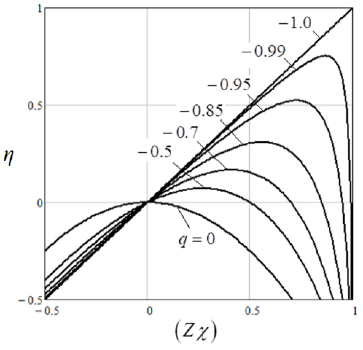
As can be seen from the obtained results (40), the coefficient of coupling q of the PC modelling the SPMSM vector controlled by the
id = 0 method, for the case without taking into account iron losses, is equal to –1 and does not depend on the mode parameters of the machine. In this case, the SPMSM is modeled by only one substitute scheme determined by the coordinate
q, but without resistance
Rc (
Figure 1(b)). Therefore, the current
iq completely forms an electromagnetic torque, that is, it is directly linked with the output current. For the case of taking into account iron losses, the resistance
Rc appears in the substitute circuit, through which a part of the input current is closed. In this way, there is already an incomplete coupling between the input and output of the PC, and the coefficient of coupling is determined through the value
A according to (40). With a decrease in the angular velocity of the machine,
A decreases because, according to (25), the value of the resistance
Rc decreases. For the machine under study, when the relative angular velocity ω
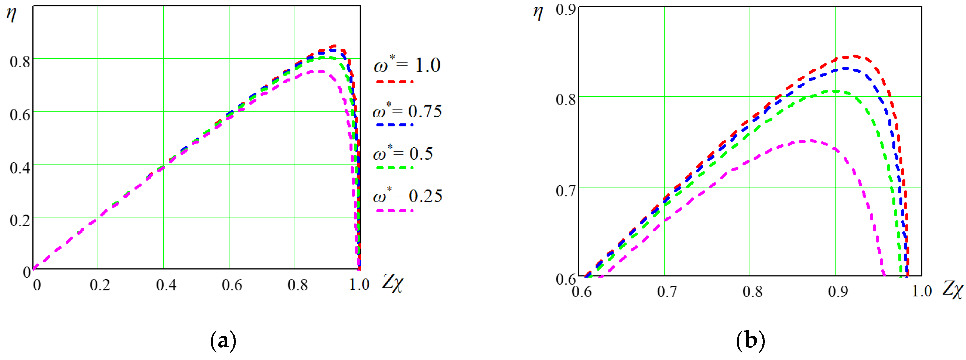
* decreases from 1 to 0.25, the value of q changes from -0.9965 to -0.9898. The maximum energy efficiency of such a machine, according to (17), also decreases from 0.845 to 0.751 (
Figure 3). The value of (
Zχ)
opt also decreases from 0.919 to 0.867.
The value of the SPMSM operating point
Zχ, in turn, depends on the values of two main variables – the angular velocity of the machine
ω and the load torque
TL, which directly affect the value of
vq. The value of the latter was calculated from equations (6), (8) and (9) under the following conditions:
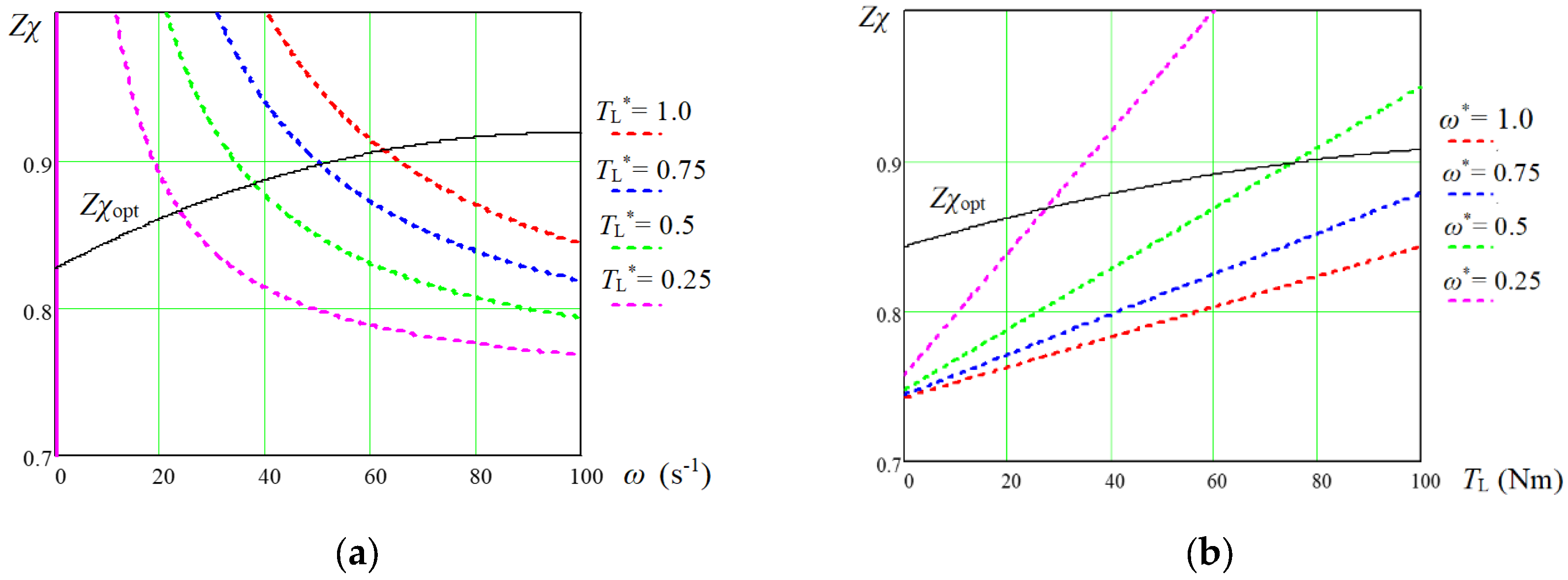
Figure 4 shows how the dimensionless indicator
Zχ of the operating mode of the experimental machine depends on the fixed values of the main variables
ω and
TL. As can be seen from this figure, the optimal value of (
Zχ)
opt, and therefore the maximum efficiency of the machine, is achieved only with a certain combination of values
ω and
TL. The following relationship between the variables ω and
TL corresponds to (
Zχ)
opt curve:
In
Figure 4 both above and below the curves shown (
Zχ)
opt, the energy efficiency of the SPMSM decreases, and the lower part corresponds to the left side of the
η(
Zχ) characteristics shown in
Figure 3, and the upper part is on the right side of the
η(
Zχ) characteristics. As can be seen from
Figure 4(a), the parts of the obtained dependences, which lie below the (
Zχ)
opt curve, correspond to higher angular velocities of the machine. For them, the value of
Zχ does not decrease below 0.76. This means that energy efficiency will not be less than 0.75 even at the nominal load torque. The situation can be worse at low motor angular velocities, which are characterized by the upper parts of the dependences in relation to the (
Zχ)
opt curves in
Figure 4. As can be seen from
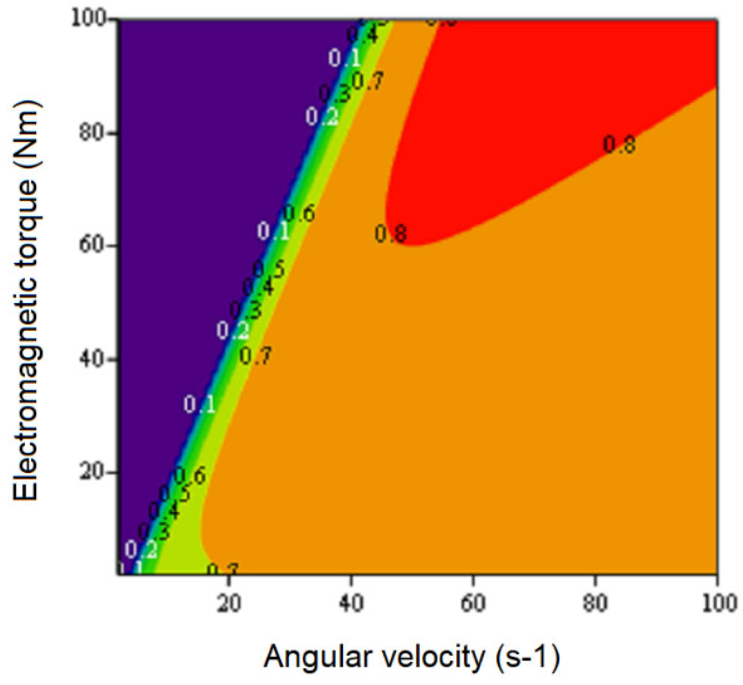
Figure 4(a), there is a limitation regarding the maximum load torque, below which the energy efficiency can rapidly decrease to zero. At the same time, the smaller the angular velocity of the SPMSM, the smaller the load torque permissible for a given level of efficiency. The obtained regularity can be clearly seen from the efficiency map, which is constructed for the experimental SPMSM in
Figure 5. As the resulting map shows, high energy efficiency is ensured in a fairly wide range starting from the minimum angular speed, at which the machine starts to develop an electromagnetic torque, up to the nominal load and higher. However, it can be seen from the obtained efficiency map that the SPMSM, which is controlled according to the
id = 0 criterion, cannot provide sufficient electromagnetic torque for EVs at low drive speeds. During acceleration of the experimental machine, as can be seen from
Figure 5, its electromagnetic torque will increase gradually, and will reach its nominal value only after half of the nominal value of the angular velocity. Unfortunately, there are no other options to change the SPMSM performance map.
3.4. Efficiency Optimization of IPMSM Operation Below the Rated Speed
As can be seen from the nonlinear mathematical model of IPMSM for its steady-state operation – from systems of equations (8) and (9), as well as from complex expressions for the input force and flow (28), obtain analytical expressions for the kinetic coefficients of the PC that describe the operation of this machine, is impossible. Therefore, the research method for this case remains only numerical. Since the system is clearly nonlinear, the PC parameters will change depending on the working point of the machine - the set values of the angular velocity ω0 and the load torque TL0. For a given pair of values of these variables, it is necessary to linearize the system and obtain the PC parameters.
As is known [9], already in the first range of angular velocity regulation of the IPMSM, the energy efficiency of its operation also depends on the value of the armature current component id. Even for the classic case – without taking into account iron losses – it is not possible to obtain analytical expressions for the dependencies of the optimal values of the components of the armature current on the value of only the load torque - the MTPA curve [35]. If iron losses are also taken into account, even with the help of such a simple model, which is used in this work, it will not be possible to obtain such analytical dependencies. Therefore, for the purpose of numerical energy optimization of IPMSM taking into account iron losses, it is necessary to introduce one more variative variable. As the analysis showed, it is easiest to choose the component of the armature current id0, which determines the reactive component of the electromagnetic torque. Therefore, further calculations should be carried out as a function of this variable.
Therefore, it is advisable to build the IPMSM mathematical model taking into account iron losses, for successive numerical calculations, based on the systems of equations (8), (9) and expressions (28) in the following view:
Having the set parameters of the working point of the machine
ω =
ω0 and
TL =
TL0, as a result of cyclic calculations according to expressions (43)-(49) for points in the range
id0 = 0 – (-100) A, the final dependences
va(
id0) and
ia(
id0), which characterize the input power of the PC depending on the value of component of the armature current
id0, are obtained at a given output power
Po(
ω0,
TL0). Thus, for each value of
id0 there is a pair of the PC input and output coordinates - flow
X and force
J. However, these values are not enough to determine three kinetic coefficients from two equations in system (29). To obtain one more point of the linear PC, it is necessary to linearize the obtained dependences of the input force
va(
id0) and the input flow
ia(
id0) of the PC on the output coordinates of the force ω and the flow
TL at the given point (
ω0,
TL0). To obtain such linear dependences, similar calculations were carried out according to expressions (43)-(49), but for points equidistant to the left and right of the given point at some insignificant distances: once by the value of
ω0 for
TL =
TL0, and the second time by the value of
TL0 for
ω =
ω0. Four linear dependences of the input flow and force on the output flow and force at the given point (
ω0,
TL0) were found based on the pairs of values
va(
id0) and
ia(
id0) obtained at these points, and depending on
id0. Attempts to apply points from the obtained linear dependencies to determine the kinetic coefficients showed that if even two points from different dependencies are taken, then the values of the kinetic coefficients
Lio and
Loi determined from the two equations of system (29) will be different. Therefore, only one linearized dependence was taken –
va(
id0) in the function
ω, which the least of all obtained differs from the linear character that leads to the smallest calculation error. From this dependence, one point was determined – the voltage value
va(
id0) at
ω = 0:
where
are the angular coefficients of the linear dependences of
va on
ω found for different values of
id0.
The value of the kinetic coefficients was carried out in the following order.
From the second equation of system (29) for
ω = 0 is obtained
From the first equation of system (29) for the working point of the PC is found
From the second equation of system (29) for the working point of the PС is determined
With the use of kinetic coefficients (51)-(53) according to expressions (12)-(14), dependences on the main parameters of the PC and the indicator of the energy efficiency of the experimental IPMSM taking into account iron losses were obtained: q(id0), Zχ(id0), and η(id0).
According to the described algorithm, a program was created in the MathCad environment that allows you to calculate the specified parameters and performance indicators of the PC, which models the operation of the experimental IPMSM taking into account iron losses for different operating points of the machine depending on the component of the armature current id0.
To check the correctness of the algorithm, the first computational experiment was conducted for the variant whose results can be determined analytically – for the IPMSM without taking into account iron losses. Having set three orders of magnitude higher than the real value of
Rc in the model, the results were obtained for the nominal angular velocity of the machine and for the values of the load torque of 0.25
Tn, 0.5
Tn, 0.75
Tn, and 1.0
Tn, which are shown in
Figure 6.
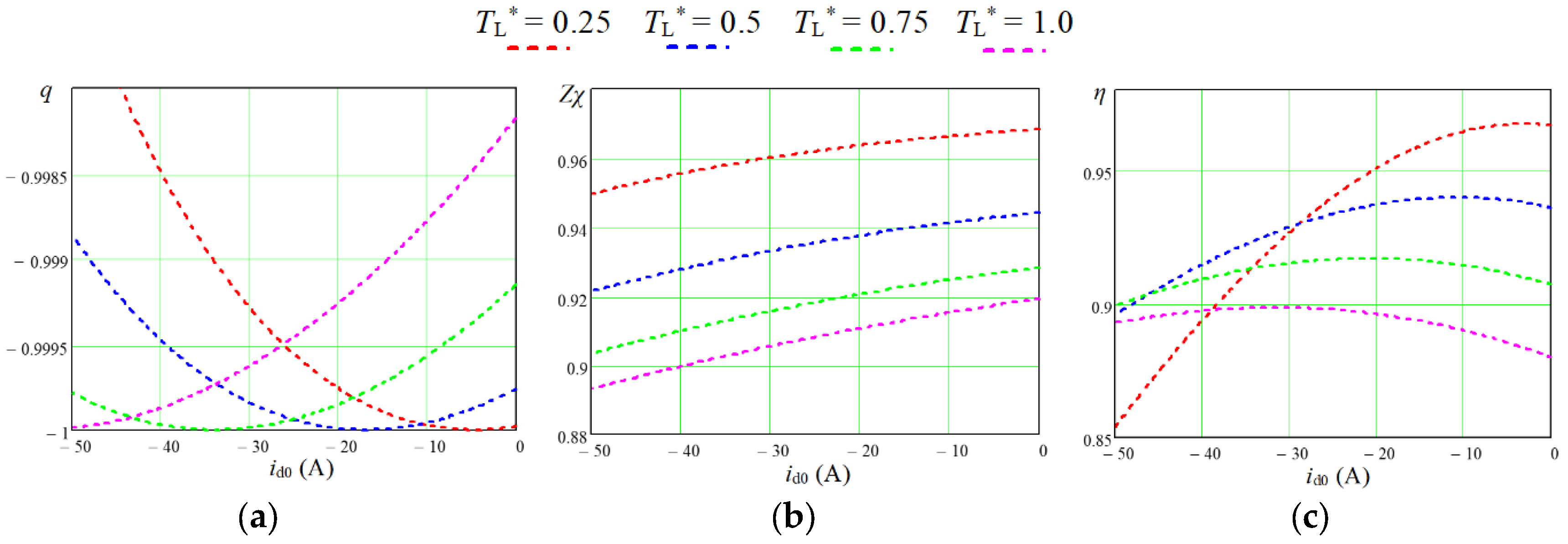
From the dependences
η(
Zχ) shown in
Figure 6, the value of the current component
id0, at which the maximum energy efficiency is achieved, were obtained that are listed in
Table 2. Since in the case of not taking into account iron losses,
id0 =
id, these values should correspond to the values of the MTPA curve. In [24], the dependence in p. u. between the electromagnetic torque and the component of the armature current
id for IPMSM at the points of the MTPA curve is given as
where the relative values are normalized to the corresponding base values
For calculation, a numerical dependence was obtained from expression (54) in [24]:
Calculated using (54)-(56) for the experimental IPMSM
id values from the MTPA curve are given in
Table 2. The deviation obtained according to the developed algorithm from the corresponding values obtained analytically does not exceed 1.5 A for medium and high loads, which is less than 10% for medium loads and less than 5% for the nominal motor load torque. This is an acceptable result for these studies and indicates the adequacy of the proposed research method and algorithm for calculating the parameters and performance indicators of IPMSM taking into account iron losses.
From
Figure 6, it can be seen that even without taking into account in the IPMSM iron losses the coefficient of coupling decreases.
q = –1, i.e. full coupling for each loads occurs only for the one value of
id0, i.e. for a certain optimal ratio between the components of the armature current
id0 and
iq0. With other ratios between these components, which also provide the required electromagnetic torque of the machine, the coupling between the input and output will already be incomplete. This can be explained by the different contribution of the components of the armature current to the production of the electromagnetic torque according to (6) and the two substitute circuits that work in this case (
Figure 1). With different from the optimal ratios between the components of the armature current, there is a "slippage" of power in one of the circuits or in two circuits together.
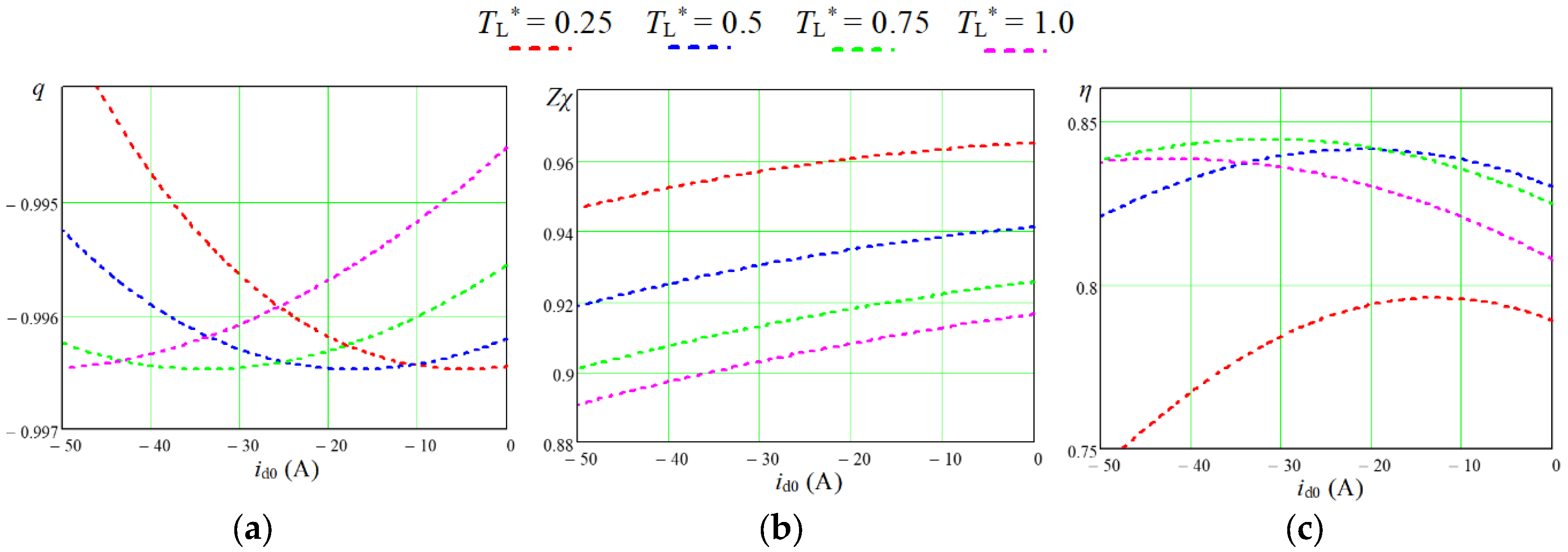
In
Figure 7 are similar to those shown in
Figure 6 dependencies obtained by the developed calculation program for the experimental IPMSM taking into account iron losses.
Comparison of the results shown in
Figure 7 with the similar ones shown in
Figure 6 makes it possible to draw the following conclusions. Taking into account iron losses leads to a decrease in the modulus of the PC coefficient of coupling, which simulates the operation of the machine (
Figure 7(a)) and a shift of its maximum towards higher values of the id0 current component. The values of the maximum energy efficiency under medium and high loads of the drive (
TL* = 0.5 – 1.0) are reduced by taking into account the iron losses by 5-9% compared to the option without taking into account these losses (
Figure 7(c)). In the case of low drive load (
TL* = 0.25),
η is reduced by as much as 17%, which is explained by the relative increase in the effect on
η of losses in steel compared to reduced losses in copper. The points of maximum energy efficiency are also shifted towards larger values of the
id0 current component, which are very close to similar values of this current, at which the maximum value of the coefficient of coupling is ensured. Similar regularities also occur for other values of IPMSM angular velocity.
Thus, the presence of one more variable coordinate – the id0 current component – makes it possible to ensure the operation of the IPMSM taking into account the iron losses at the points of maximum energy efficiency. The developed technique makes it possible to obtain optimal values of id0.opt for each pair of values of the operating point of the drive - angular velocity and load torque.
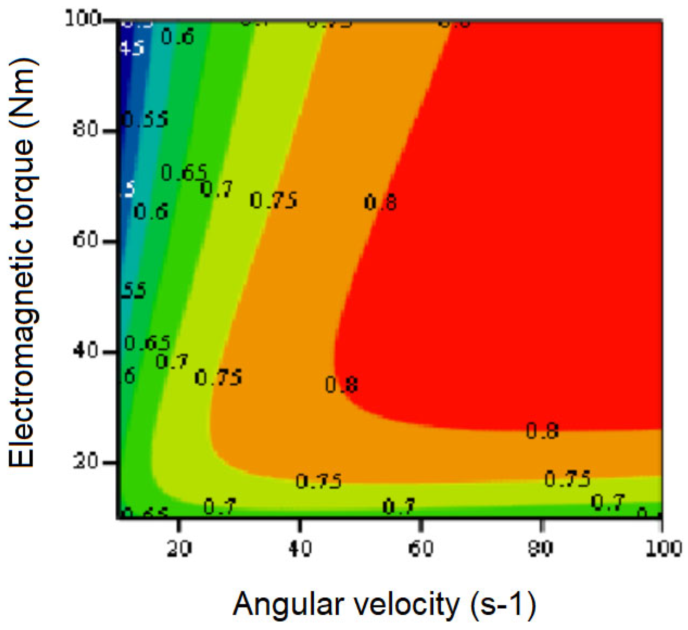
Figure 8 presents the efficiency map obtained for the experimental IPMSM taking into account iron losses, which operates at the points of maximum energy efficiency at optimal values of the
id0.opt current component. The map is calculated using the same created program; however,
id0.opt is needed at each step of the calculations for the running values of the machine's angular velocity and torque. Such values were obtained in the program by interpolation from the dependence
id0.opt (
ω,
TL), previously obtained from experiments similar to those shown in
Figure 7 carried out for a number of angular velocities of the experimental machine. Since the above dependence is smooth, the interpolation error did not exceed 2%. A comparison of the obtained efficiency map for IPMSM with the efficiency map for SPMSM (
Figure 5) shows the advantages of the first over the second, which are the ability to provide a large starting torque and a wider zone of maximum energy efficiency – more than 0.8.
Based on the given results of the IPMSM operation with different loads at the nominal angular velocity, it is possible to easily calculate, based on (22) and (23), the power loss components caused by the imbalance of the power conversion process Δ
PR and incomplete coupling of the PC Δ
Pq. The calculation procedure is as follows. From
Figure 7(b), the values of the current component
id0.opt for each load are obtained. For each of
id0.opt from
Figures 7(a) and 7(b), the values of
q and
Zχ are defined, which are used to find the power loss components in p. u. using (22) and (23). For each of the loads, the value of the input force
Xi =
vs(
id0.opt) and the kinetic coefficient
Lii(
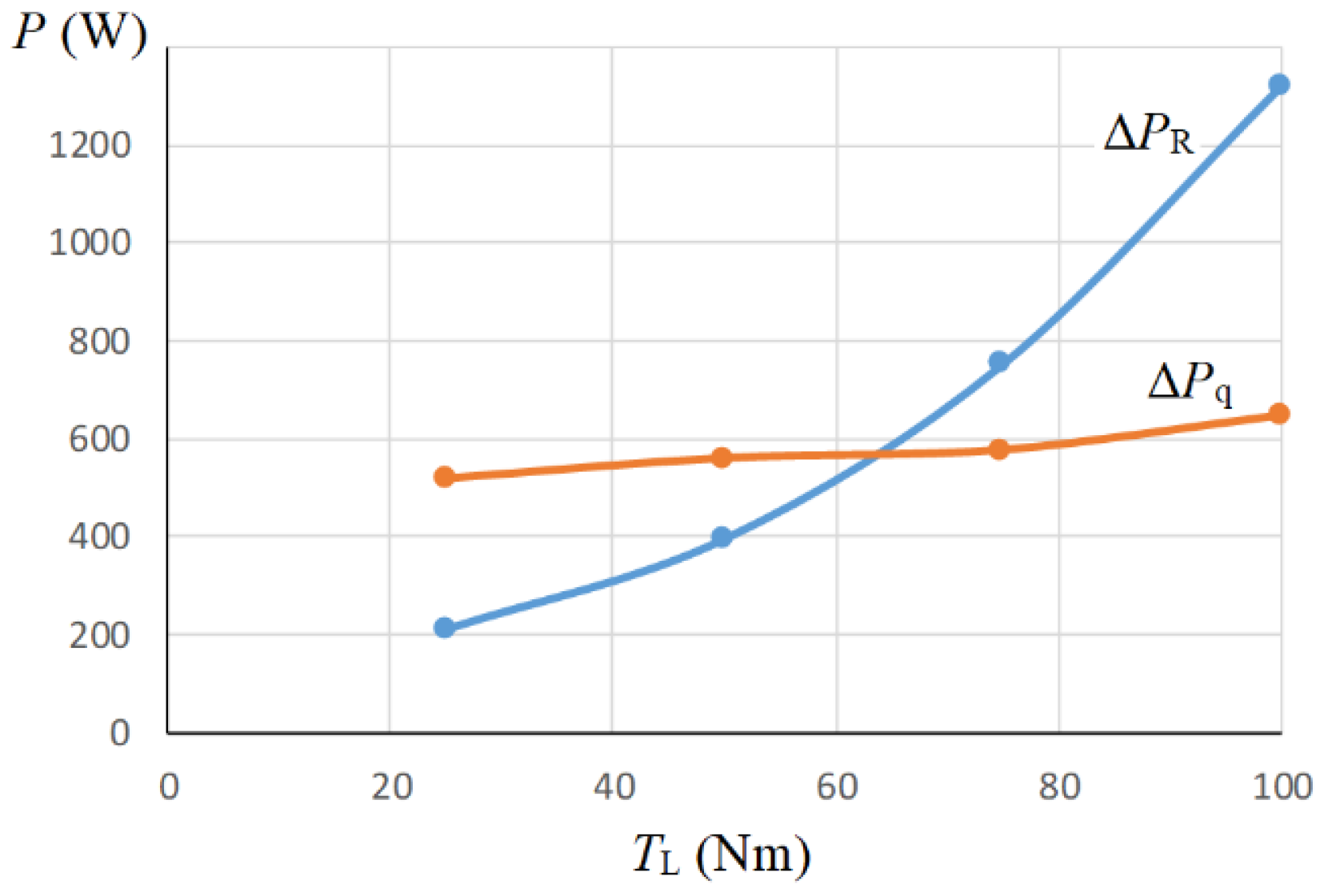
id0.opt) are determined from the program. Based on the obtained data, the absolute values of the components of power losses were found using the same expressions (22) and (23). Their dependence on the IPMSM load is shown in
Figure 9.
As can be seen from the obtained results, the losses from incomplete coupling ΔPq, which are caused primarily by losses in steel, at a constant motor angular velocity depend very little on the drive load, while the losses from the imbalance of the process ΔPR, which are the heating losses in the armature windings, rapidly increase with an increase in the load torque of the drive.
3.5. Efficiency Optimization of IPMSM Operation Above the Rated Speed
The numerical simulation algorithm of the IPMSM taking into account iron losses operation developed with the use of the LNTD is quite suitable for modelling their operation in the second region of angular velocity regulation - above its nominal value. The difference between IPMSM operation in the second region compared to the first one is the presence of a limitation on the armature voltage that is caused by the value of the DC voltage
VDC of the VI power supply, as well as a limitation on the armature current in the long-term operating mode that is caused by the heating of the motor. These restrictions are described by the following inequalities [5]:
where
vs.max is the maximum value of the armature voltage amplitude in the two-phase reference frame and
is.max is the maximum value of the armature current amplitude in the two-phase reference frame in the long-term motor operating mode.
The
vs.max value is related to
VDC by the following relationship:
With the use of the developed calculation program in the MathCad environment, work was simulated in the second region of the experimental IPMSM taking into account the iron losses, similarly as it was done for the first region.
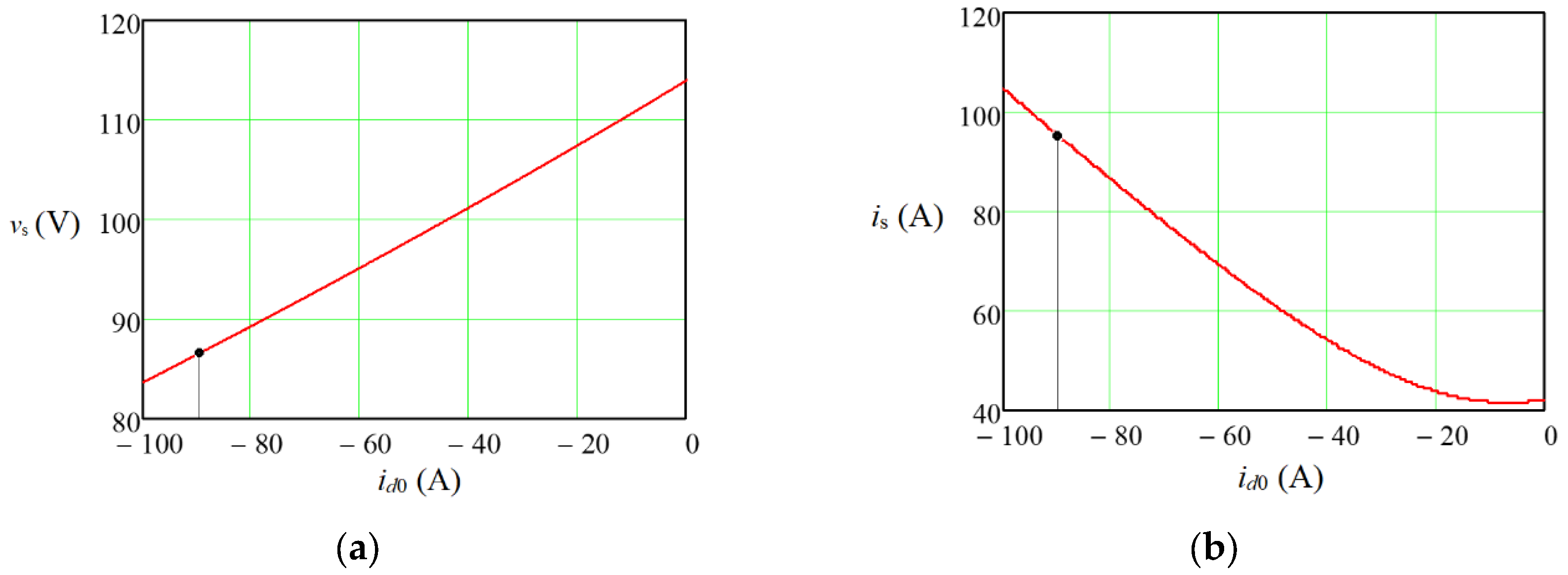
At the beginning, for the nominal operating mode of the machine – the nominal values of the angular velocity and the load torque – the vs.max and is.max values were determined by (57) and (58): vs.max = 87 V and is.max = 93.5 A. According to (59), the required value for this is VDC = 150 V.
Further studies were carried out for the relative angular velocity of IPMSM equal to
ω* = 1.5. The research methodology consisted in reducing the motor load torque to such a value that the voltage vs decreased to
vs.max. As a result, the value of the load torque
TL = 38 Nm, which was permissible from the point of view of current limitation, was obtained (
Figure 10). At the same time, the optimal
id0 value for ensuring the specified maximum torque was -90A. Dependencies of the main parameters and characteristics for the PC, which models of the experimental IPMSM operation on the value of such armature current component
id0 during machine operation in the second region with an angular velocity of 150 s-1 for the maximum value of a load torque of 38 Nm are shown in
Figure 11. As can be seen from the figure, at the operating point, the degree of coupling is
q = –0.9923, and the energy efficiency of the IPMSM is
η = 0.750. At the same time, for the optimal value
id0 = –23 A for this load
η = 0.828. However, for such a regime, the required value of
vs is 107 V, which is significantly more than the nominal value (
Figure 10(a)).
Analyzing the dependencies presented in
Figure 11, it can be concluded that the operation of the IPMSM in the second angular velocity control region is characterized by a significant shift of the operating point from the point of maximum energy efficiency. This is explained by the need to set such a value of the armature current component
id0, which would provide the task of increased angular velocity while limiting the value of the armature voltage at the nominal level. When the angular velocity increases, the armature voltage remains unchanged, but the armature current increases (
Figure 10(b)), which leads to a decrease in energy efficiency. The higher the given angular velocity, the larger the id0 value will be, and the lower the energy efficiency will be. That is, when working in the second region, the
id0 value is assigned a different task than energy optimization, as it was in the first region. Hence, accordingly, a decrease in the energy efficiency of the machine. When the load torque decreases below the permissible value of 38 Nˑm for a given angular velocity, the energy efficiency decreases even more. Thus, at the same angular velocity of the machine of 150 s
-1, the decrease of
TL to 18 Nˑm leads to a decrease of
id0 to -70 A, but η decreases already to 0.657.
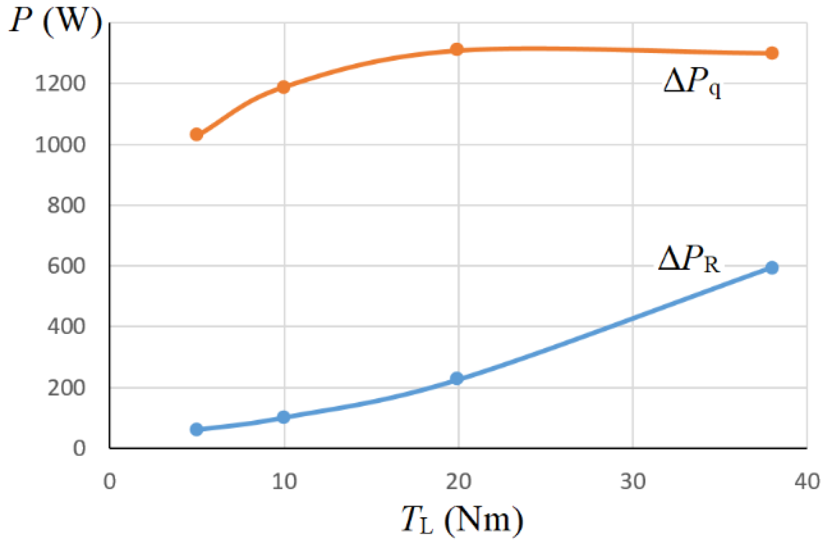
To analyze the energy regularities of IPMSM operation in the second region of angular velocity regulation, for the last experiment, the components of power loss due to process imbalance Δ
PR and the PC incomplete coupling Δ
Pq on the drive load torque
TL were calculated according to the algorithm described in subsection 3.4 (
Figure 12). The
TL varied from 5 Nm to the maximum permissible value of 38 Nm for a given angular velocity of 150 s
-1.
The nature of the components of power losses in IPMSM during its operation in the second region of angular velocity regulation obtained in
Figure 12 is radically different from the nature of these losses in the first region shown in
Figure 9. Although the total value of power losses at the maximum load of the drive differs slightly, and, in the second region, the iron losses clearly prevail over the copper losses. As in the previous case, the iron losses slightly depend on the drive load, since the motor angular velocity is unchanged, but in the second region, these losses are approximately twice as large as in the first one. Losses in copper are also higher in the second region than in the first one for the same value of the load torque. This is explained by the significant value of the current component id0, at the level of (–65) – (–90) A, compared to this component in the range (–13) – (–43) A in the first region. As a result of the significant losses and the low value of the electromagnetic torque of the motor, despite its higher angular velocity, the energy efficiency of the IPMSM in the second region decreases (from 0.365 to 0.745 in the computational experiment) compared to the first region (from 0.795 to 0.845).

