Submitted:
22 October 2024
Posted:
24 October 2024
You are already at the latest version
Abstract
Keywords:
1. Introduction
2. Methodology
- Parallel-parallel and interconnected manipulators (the first and fifth types in the classification above) are rarely used in practice because of their complex design.
- Quasi-serial manipulators (the fourth type) are often treated as well-studied serial manipulators, and a review of these systems has also been performed recently [30].
- There were no recent reviews of parallel-serial manipulators of the second type, while these manipulators are becoming more popular and widespread in practice nowadays.
- The papers discuss parallel-serial manipulators of the second type and not the other types.
- The papers primarily focus on parallel-serial manipulators and not on the parallel manipulator.
- Patents and theses are not included in this review.
- First, we used Scopus to search for papers that considered parallel-serial or hybrid manipulators, robots, and mechanisms. For this purpose, we defined the following search request: TITLE-ABS-KEY((hybrid OR (parallel W/0 seri*)) W/0 (manip* OR robot* OR mechan*)). The results were then limited to the engineering field. At that moment, we had 2512 articles (17 September 2024). After excluding inappropriate publications according to the criteria above, we selected 280 papers.
- Next, we examined the references in the selected publications using the same criteria and repeated this process for each new paper. After this step, we got 368 papers.
- Finally, we checked the citations of each selected work in Google Scholar and defined the following search request for each set of citations: (hybrid OR (parallel-seri*)). After that, we repeated this procedure for each newly obtained paper. As a result, we got 510 papers, which were included and analyzed in this review.
3. Applications and Architectures
3.1. Machining
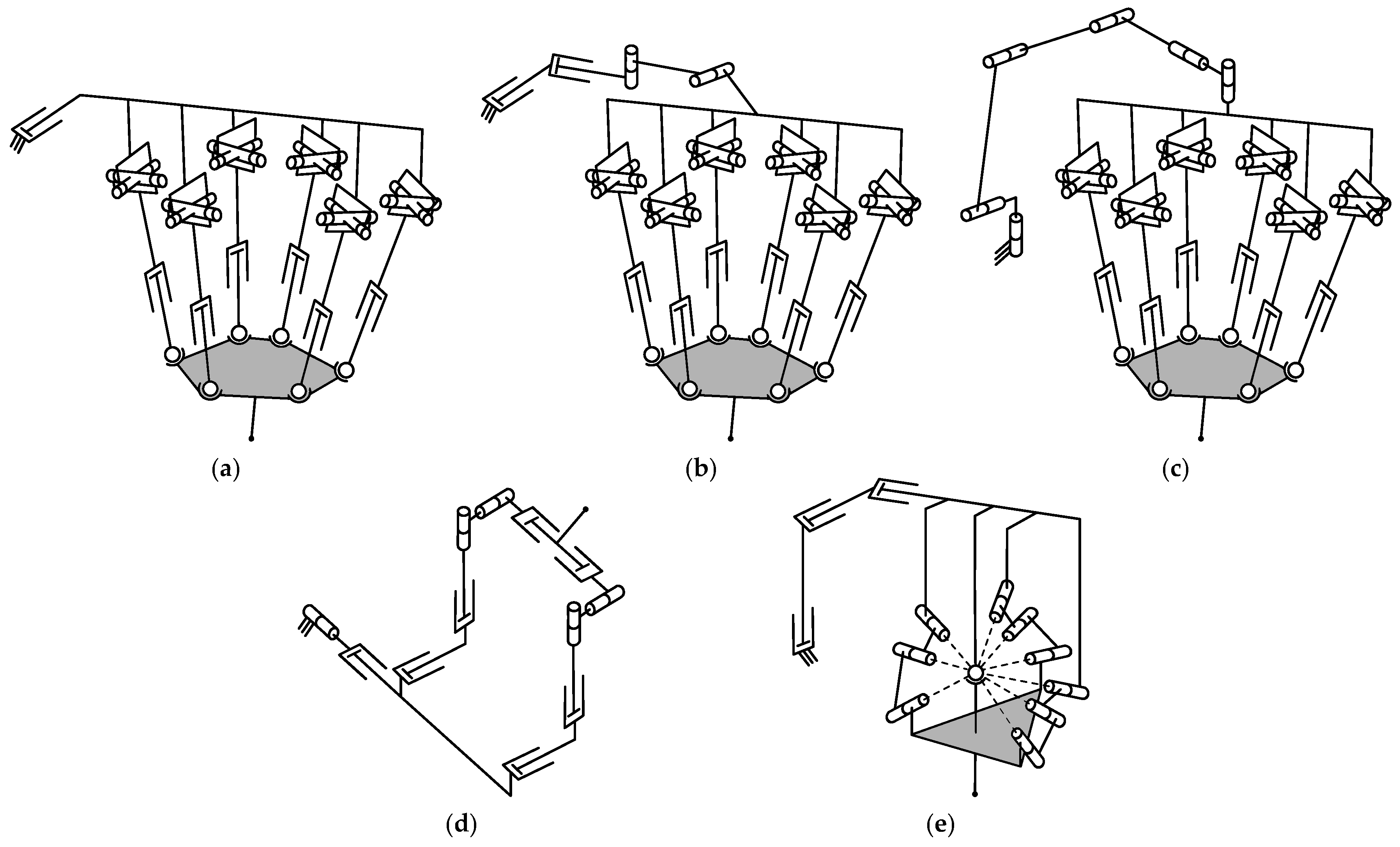
3.1.1. Manipulators Based on the Tricept Parallel Mechanism
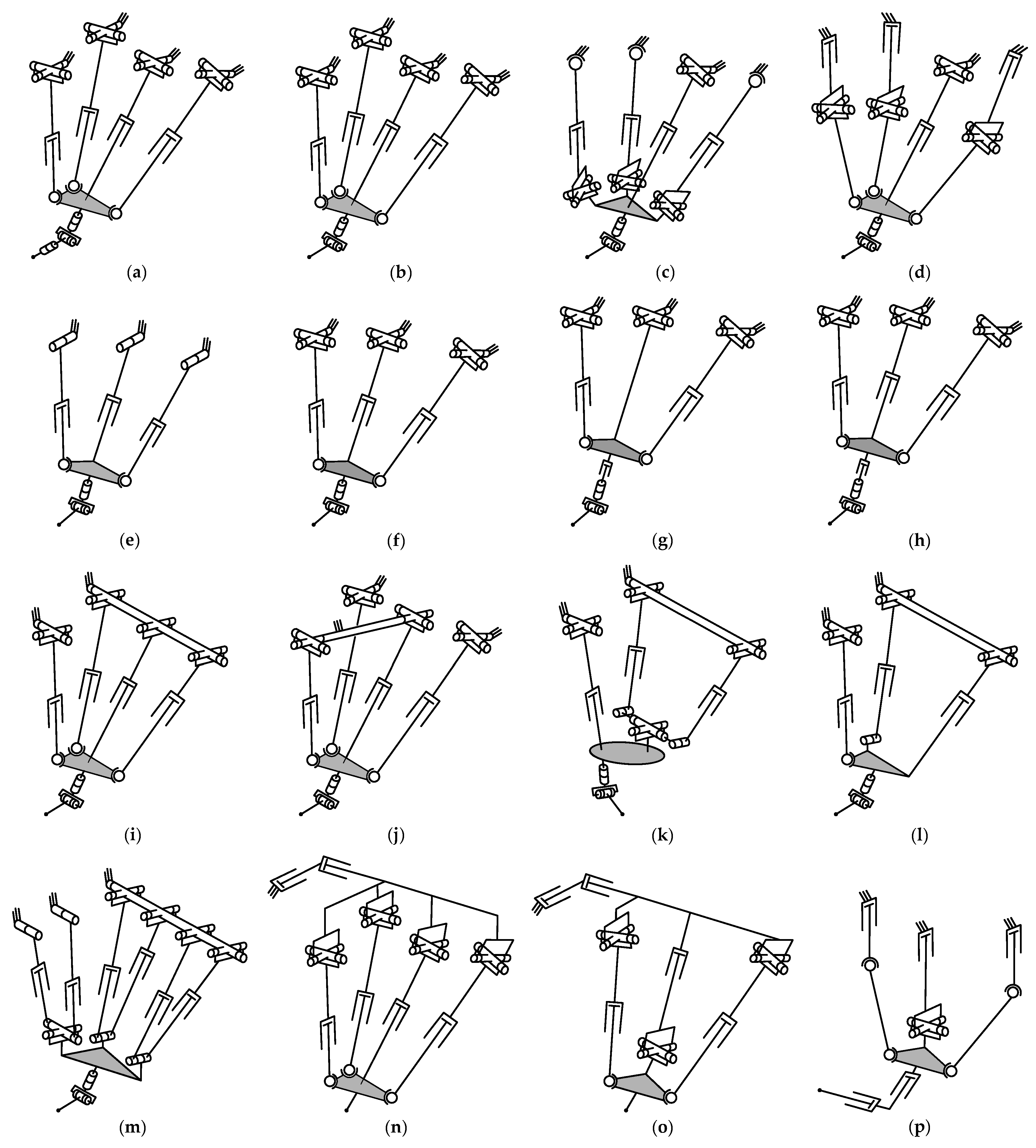
3.1.2. Manipulators Based on the Sprint Z3 Parallel Mechanism
3.1.3. Manipulators Based on the Exechon Parallel Mechanism
3.1.4. Manipulators Based on Planar Parallel Mechanisms
3.1.5. Manipulators Based on the Delta Parallel Mechanism
3.1.6. Manipulators Based on the Gough–Stewart Platform
3.1.7. Other Manipulators
3.2. Medicine
3.2.1. Manipulators for Minimally Invasive Surgery
3.2.2. Manipulators for Non-minimally Invasive Surgery
3.2.3. Manipulators for Fracture Reduction
3.2.4. Manipulators for Rehabilitation
3.2.5. Other Manipulators
3.3. Pick-and-Place and Manipulation
3.3.1. Non-kinematically Redundant Manipulators
3.3.2. Kinematically Redundant Manipulators
3.4. Humanoids and Legged Systems
3.5. Haptic Devices
3.6. Additive Technologies
3.7. Simulators
3.8. Orienting Devices
3.9. Ocean Wave Compensation
3.10. Other Applications
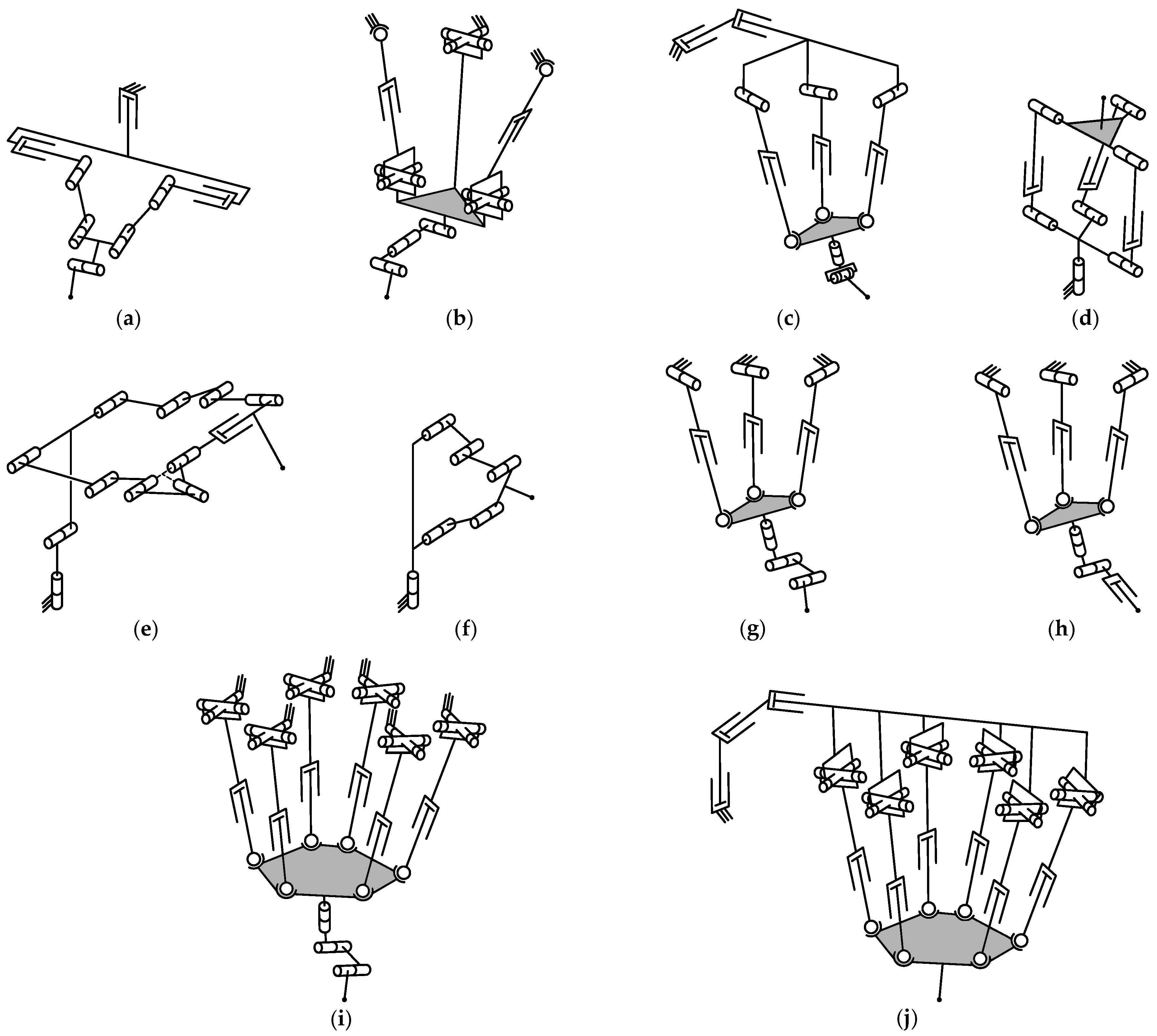
4. Design and Analysis
4.1. Type Synthesis
4.2. Mobility Analysis
4.3. Position Analysis
4.4. Instantaneous Kinematic Analysis
4.5. Singularity Analysis
4.6. Workspace Analysis
4.7. Dynamic Analysis
4.8. Performance Evaluation
4.8.1. Kinematic Performance
4.8.2. Static Performance
4.8.3. Dynamic Performance
4.9. Dimensional Synthesis
4.10. Control
4.11. Calibration
5. Discussion
5.1. Applications and Architectures
5.2. Design and Analysis
5.3. Perspectives
- New applications of parallel-serial manipulators. Although machining remains the most popular application of hybrid robots, some novel applications have appeared in the last decade, such as ocean wave engineering, additive technologies, or medicine operations considered in this review. We believe parallel-serial manipulators will find other applications in the near future as well.
- New architectures of parallel-serial manipulators. The diversity of architectures presented in this review indicates that scholars continue developing new manipulators in search of the best design. At the same time, most hybrid robots rely on parallel mechanisms with two or three DOFs and typical motion types, while 6-DOF parallel mechanisms in kinematically redundant systems are represented just by the Gough–Stewart platform. It looks attractive and promising to study hybrid architectures where parallel mechanisms have four or five DOFs and non-typical motion types.
- Comprehensive methods of design and analysis. Despite a large number of studies devoted to parallel-serial manipulators, many works focus on the design and analysis of only the parallel part. In particular, papers devoted to type synthesis, singularity analysis, performance evaluation, and dimensional synthesis of hybrid robots usually concentrate on the parallel mechanism and ignore the serial chain. Developing methods that will analyze the full parallel-serial architecture also appears promising for future studies.
6. Conclusions
Funding
Institutional Review Board Statement
Informed Consent Statement
Data Availability Statement
Conflicts of Interest
References
- Ye, W.; Tang, T.; Li, Q. Robotized manufacturing equipment: a review from the perspective of mechanism topology. Sci. China Technol. Sci. 2023, 66, 1683–1697. [Google Scholar] [CrossRef]
- Peters, B.S.; Armijo, P.R.; Krause, C.; Choudhury, S.A.; Oleynikov, D. Review of emerging surgical robotic technology. Surg. Endosc. 2018, 32, 1636–1655. [Google Scholar] [CrossRef] [PubMed]
- Gonzalez-Aguirre, J.A.; Osorio-Oliveros, R.; Rodríguez-Hernández, K.L.; Lizárraga-Iturralde, J.; Morales Menendez, R.; Ramírez-Mendoza, R.A.; Ramírez-Moreno, M.A.; Lozoya-Santos, J.J. Service robots: trends and technology. Appl. Sci. 2021, 11, 10702. [Google Scholar] [CrossRef]
- Flores-Abad, A.; Ma, O.; Pham, K.; Ulrich, S. A review of space robotics technologies for on-orbit servicing. Prog. Aerosp. Sci. 2014, 68, 1–26. [Google Scholar] [CrossRef]
- Sivčev, S.; Coleman, J.; Omerdić, E.; Dooly, G.; Toal, D. Underwater manipulators: a review. Ocean Eng. 2018, 163, 431–450. [Google Scholar] [CrossRef]
- Ceccarelli, M. Fundamentals of Mechanics of Robotic Manipulation, 2 ed.; Springer: Cham, Switzerland, 2022. [Google Scholar] [CrossRef]
- Karupusamy, S.; Maruthachalam, S.; Veerasamy, B. Kinematic modeling and performance analysis of a 5-DoF robot for welding applications. Machines 2024, 12, 378. [Google Scholar] [CrossRef]
- Borrell, J.; Perez-Vidal, C.; Segura, J.V. Optimization of the pick-and-place sequence of a bimanual collaborative robot in an industrial production line. Int. J. Adv. Manuf. Technol. 2024, 130, 4221–4234. [Google Scholar] [CrossRef]
- Zhu, Z.; Hu, H. Robot learning from demonstration in robotic assembly: a survey. Robotics 2018, 7, 17. [Google Scholar] [CrossRef]
- Russo, M.; Zhang, D.; Liu, X.J.; Xie, Z. A review of parallel kinematic machine tools: design, modeling, and applications. Int. J. Mach. Tools Manuf. 2024, 196, 104118. [Google Scholar] [CrossRef]
- Huang, X.; Rendon-Morales, E.; Aviles-Espinosa, R. ROMI: design and experimental evaluation of a linear Delta robotic system for high-precision applications. Machines 2023, 11, 1072. [Google Scholar] [CrossRef]
- Müller, A.; Zlatanov, D. (Eds.) Singular Configurations of Mechanisms and Manipulators; Springer: Cham, Switzerland, 2019. [Google Scholar] [CrossRef]
- Liu, Q.; Liu, H.; Xiao, J.; Tian, W.; Ma, Y.; Li, B. Open-architecture of CNC system and mirror milling technology for a 5-axis hybrid robot. Robot. Comput. Integr. Manuf. 2023, 81, 102504. [Google Scholar] [CrossRef]
- Tao, B.; Feng, Y.; Fan, X.; Lan, K.; Zhuang, M.; Wang, S.; Wang, F.; Chen, X.; Wu, Y. The accuracy of a novel image-guided hybrid robotic system for dental implant placement: an in vitro study. Int. J. Med. Rob. Comput. Assisted Surg. 2023, 19, e2452. [Google Scholar] [CrossRef]
- He, J.; Zheng, H.; Gao, F.; Zhang, H. Dynamics and control of a 7-DOF hybrid manipulator for capturing a non-cooperative target in space. Mech. Mach. Theory 2019, 140, 83–103. [Google Scholar] [CrossRef]
- Nayak, A.; Caro, S.; Wenger, P. Kinematic analysis of the 3-RPS-3-SPR series–parallel manipulator. Robotica 2019, 37, 1240–1266. [Google Scholar] [CrossRef]
- Gallardo-Alvarado, J. Unified infinitesimal kinematics of a 3-RRR/PRR six-degree-of-freedom parallel-serial manipulator. Meccanica 2023, 58, 795–811. [Google Scholar] [CrossRef]
- Elsamanty, M.; Faidallah, E.M.; Hossameldin, Y.H.; Abd Rabbo, S.M.; Maged, S.A. Design, simulation, and kinematics of 9-DOF serial-parallel hybrid manipulator robot. 2021 3rd Novel Intelligent and Leading Emerging Sciences Conference; , 2021; pp. 370–375. [CrossRef]
- Wang, F.S.; Chen, S.L. Geometric error measurement and compensation of a six-degree-of-freedom hybrid positioning stage. Proc. Inst. Mech. Eng., Part B: J. Eng. Manuf. 2008, 222, 185–200. [Google Scholar] [CrossRef]
- Fajardo-Pruna, M.; López-Estrada, L.; Pérez, H.; Diez, E.; Vizán, A. Analysis of a single-edge micro cutting process in a hybrid parallel-serial machine tool. Int. J. Mech. Sci. 2019, 151, 222–235. [Google Scholar] [CrossRef]
- Klimchik, A.; Pashkevich, A. Serial vs. quasi-serial manipulators: comparison analysis of elasto-static behaviors. Mech. Mach. Theory 2017, 107, 46–70. [Google Scholar] [CrossRef]
- Zeng, Q.; Fang, Y. Structural synthesis and analysis of serial–parallel hybrid mechanisms with spatial multi-loop kinematic chains. Mech. Mach. Theory 2012, 49, 198–215. [Google Scholar] [CrossRef]
- Huang, P.; Wang, J.; Wang, L.; Yao, R. Kinematical calibration of a hybrid machine tool with regularization method. Int. J. Mach. Tools Manuf. 2011, 51, 210–220. [Google Scholar] [CrossRef]
- Chong, Z.; Xie, F.; Liu, X.J.; Wang, J.; Niu, H. Design of the parallel mechanism for a hybrid mobile robot in wind turbine blades polishing. Robot. Comput. Integr. Manuf. 2020, 61, 101857. [Google Scholar] [CrossRef]
- Sun, P.; Li, Y.B.; Wang, Z.S.; Chen, K.; Chen, B.; Zeng, X.; Zhao, J.; Yue, Y. Inverse displacement analysis of a novel hybrid humanoid robotic arm. Mech. Mach. Theory 2020, 147, 103743. [Google Scholar] [CrossRef]
- Singh, A.; Singla, A.; Soni, S. D-H parameters augmented with dummy frames for serial manipulators containing spatial links. 23rd IEEE International Symposium on Robot and Human Interactive Communication; , 2014; pp. 975–980. [CrossRef]
- Li, Q.; Fucai, L.; Lihuan, L. A novel hybrid humanoid dextrous manipulator for on-orbit servicing and its kinematics analysis. 2013 Third International Conference on Instrumentation, Measurement, Computer, Communication and Control; , 2013; pp. 432–437. [CrossRef]
- Zou, Q.; Zhang, D.; Huang, G. Kinematic models and the performance level index of a picking-and-placing hybrid robot. Machines 2023, 11, 979. [Google Scholar] [CrossRef]
- Abarca, V.E.; Elias, D.A. A review of parallel robots: rehabilitation, assistance, and humanoid applications for neck, shoulder, wrist, hip, and ankle joints. Robotics 2023, 12, 131. [Google Scholar] [CrossRef]
- Kumar, S.; Wöhrle, H.; de Gea Fernández, J.; Müller, A.; Kirchner, F. A survey on modularity and distributivity in series-parallel hybrid robots. Mechatronics 2020, 68, 102367. [Google Scholar] [CrossRef]
- Neumann, K.E. Robot, 1988. US Patent 4,732,525.
- Thornton, G.S. The GEC Tetrabot – a new serial-parallel assembly robot. 1988 IEEE International Conference on Robotics and Automation; , 1988; pp. 437–439. [CrossRef]
- Choi, B.O.; Lee, M.K. Development of a hybrid robot arm for propeller grinding. In Intelligent Robots and Computer Vision XV: Algorithms, Techniques, Active Vision, and Materials Handling; Casasent, D.P., Ed.; SPIE: Bellingham, WA, USA, 1996; pp. 517–527. [Google Scholar] [CrossRef]
- Lee, M.K.; Park, K.W.; Choi, B.O. Kinematic and dynamic models of hybrid robot manipulator for propeller grinding. J. Robot. Syst. 1999, 16, 137–150. [Google Scholar] [CrossRef]
- Zhao, D.; Dong, C.; Guo, H.; Tian, W. Kinematic calibration based on the multicollinearity diagnosis of a 6-DOF polishing hybrid robot using a laser tracker. Math. Probl. Eng. 2018, 2018, 5602397. [Google Scholar] [CrossRef]
- Huang, T.; Zhao, D.; Yin, F.; Tian, W.; Chetwynd, D.G. Kinematic calibration of a 6-DOF hybrid robot by considering multicollinearity in the identification Jacobian. Mech. Mach. Theory 2019, 131, 371–384. [Google Scholar] [CrossRef]
- Ma, Y.; Liu, H.; Zhang, M.; Li, B.; Liu, Q.; Dong, C. Elasto-dynamic performance evaluation of a 6-DOF hybrid polishing robot based on kinematic modeling and CAE technology. Mech. Mach. Theory 2022, 176, 104983. [Google Scholar] [CrossRef]
- Tian, W.; Xu, M.; Zhang, X.; Guo, X.; Wang, L.; Huang, T. Repeatability prediction of 6-DOF hybrid robot based on equivalent error model of actuated joint. Measurement 2023, 207, 112377. [Google Scholar] [CrossRef]
- Han, J.; Shan, X.; Liu, H.; Xiao, J.; Huang, T. Fuzzy gain scheduling PID control of a hybrid robot based on dynamic characteristics. Mech. Mach. Theory 2023, 184, 105283. [Google Scholar] [CrossRef]
- Han, J.; Cheng, H.; Shan, X.; Liu, H.; Xiao, J.; Huang, T. A novel multi-pulse friction compensation strategy for hybrid robots. Mech. Mach. Theory 2024, 201, 105726. [Google Scholar] [CrossRef]
- Olazagoitia, J.L.; Wyatt, S. New PKM Tricept T9000 and its application to flexible manufacturing at aerospace industry. AeroTech Congress & Exhibition; , 2007; pp. 2007–01–3820.
- Siciliano, B. A study on the kinematics of a class of parallel manipulators. In Advances in Robot Kinematics: Analysis and Control; Lenarčič, J., Husty, M.L., Eds.; Springer: Dordrecht, The Netherlands, 1998; pp. 29–38. [Google Scholar] [CrossRef]
- Siciliano, B. The Tricept robot: inverse kinematics, manipulability analysis and closed-loop direct kinematics algorithm. Robotica 1999, 17, 437–445. [Google Scholar] [CrossRef]
- Milutinović, M.; Slavković, N.; Milutinović, D. Kinematic modelling of hybrid parallel-serial five-axis machine tool. FME Trans. 2013, 41, 1–10. [Google Scholar]
- Eastwood, S.; Webb, P. Compensation of thermal deformation of a hybrid parallel kinematic machine. Robot. Comput. Integr. Manuf. 2009, 25, 81–90. [Google Scholar] [CrossRef]
- Callegari, M.; Gabrielli, A.; Palpacelli, M.C.; Principi, M. Robotised cell for the incremental forming of metal sheets. ASME 8th Biennial Conference on Engineering Systems Design and Analysis; , 2006; Vol. 1, pp. 749–756. [CrossRef]
- Callegari, M.; Gabrielli, A.; Palpacelli, M.C.; Principi, M. Incremental forming of sheet metal by means of parallel kinematics machines. J. Manuf. Sci. Eng. 2008, 130, 054501. [Google Scholar] [CrossRef]
- Callegari, M.; Forcellese, A.; Palpacelli, M.; Simoncini, M. Robotic friction stir welding of AA5754 aluminum alloy sheets at different initial temper states. Key Eng. Mater. 2014, 622-623, 540–547. [Google Scholar] [CrossRef]
- Palpacelli, M.; Callegari, M.; Carbonari, L.; Palmieri, G. Theoretical and experimental analysis of a hybrid industrial robot used for friction stir welding. Int. J. Mechatron. Manuf. Syst. 2015, 8, 258. [Google Scholar] [CrossRef]
- Dong, C.; Liu, H.; Huang, T.; Chetwynd, D.G. A lumped model for dynamic behavior prediction of a hybrid robot for optical polishing. In Advances in Mechanism and Machine Science; Uhl, T., Ed.; Springer: Cham, Switzerland, 2019; pp. 2007–2016. [Google Scholar] [CrossRef]
- Dong, C.; Liu, H.; Huang, T.; Chetwynd, D.G. A screw theory-based semi-analytical approach for elastodynamics of the Tricept robot. J. Mech. Robot. 2019, 11, 031005. [Google Scholar] [CrossRef]
- Jin, Z.; Cheng, G.; Chen, S.; Guo, F. Human-machine-environment information fusion and control compensation strategy for large optical mirror processing system. Proc. Inst. Mech. Eng., Part C: J. Mech. Eng. Sci. 2021, 235, 2507–2523. [Google Scholar] [CrossRef]
- Jin, Z.; Cheng, G.; Xu, S.; Yuan, D. Error prediction for large optical mirror processing robot based on deep learning. Strojniški Vestn. - J. Mech. Eng. 2022, 68, 175–184. [Google Scholar] [CrossRef]
- Dong, K.; Li, J.; Lv, M.; Li, X.; Gu, W.; Cheng, G. Active disturbance rejection control algorithm for the driven branch chain of a polishing robot. Strojniški Vestn. - J. Mech. Eng. 2023, 69, 509–521. [Google Scholar] [CrossRef]
- Kim, J.W.; Shin, C.R.; Kim, H.S.; Kyung, J.H.; Ha, Y.H.; Yu, H.S. Error model and kinematic calibration of a 5-axis hybrid machine tool. 2006 SICE-ICASE International Joint Conference; , 2006; pp. 3111–3115. [CrossRef]
- Park, K.W.; Kim, T.S.; Lee, M.K.; Kyung, J.H. Study on kinematic optimization of a combined parallel-serial manipulator. 2006 SICE-ICASE International Joint Conference; , 2006; pp. 1212–1216. [CrossRef]
- Kyung, J.H.; Han, H.S.; Park, C.H.; Ha, Y.H.; Park, J.H. Dynamics of a hybrid serial-parallel robot for multi-tasking machining processes. 2006 SICE-ICASE International Joint Conference; , 2006; pp. 3026–3030. [CrossRef]
- Kyung, J.H.; Park, J.H.; Yu, H.S.; Han, H.S. Specification of driving constraints for dynamics simulation of a parallel-serial manipulator. 2007 International Conference on Control, Automation and Systems; , 2007; pp. 2283–2287. [CrossRef]
- Tönshoff, H.K.; Grendel, H.; Kaak, R. Structure and characteristics of the hybrid manipulator Georg V. In Parallel Kinematic Machines; Boër, C., Molinari-Tosatti, L., Smith, K., Eds.; Springer: London, UK, 1999; pp. 365–376. [Google Scholar] [CrossRef]
- Li, M.; Huang, T.; Zhang, D.; Zhao, X.; Hu, S.J.; Chetwynd, D.G. Conceptual design and dimensional synthesis of a reconfigurable hybrid robot. J. Manuf. Sci. Eng. 2005, 127, 647–653. [Google Scholar] [CrossRef]
- Huang, T.; Wang, P.F.; Zhao, X.M.; Chetwynd, D.G. Design of a 4-DOF hybrid PKM module for large structural component assembly. CIRP Annals 2010, 59, 159–162. [Google Scholar] [CrossRef]
- Wang, M.; Wang, P.; Song, Y.; Zhao, X.; Huang, T. Stiffness analysis of a 4-DOF hybrid robot. J. Mech. Eng. 2011, 47, 9–16. [Google Scholar] [CrossRef]
- Huang, T.; Li, M.; Zhao, X.M.; Mei, J.P.; Chetwynd, D.G.; Hu, S.J. Conceptual design and dimensional synthesis for a 3-DOF module of the TriVariant—a novel 5-DOF reconfigurable hybrid robot. IEEE Trans. Robot. 2005, 21, 449–456. [Google Scholar] [CrossRef]
- Liu, H.; Huang, T.; Mei, J.; Zhao, X.; Chetwynd, D.G.; Li, M.; Hu, S.J. Kinematic design of a 5-DOF hybrid robot with large workspace/limb–stroke ratio. J. Mech. Des. 2007, 129, 530–537. [Google Scholar] [CrossRef]
- Sun, T.; Song, Y.; Li, Y.; Zhang, J. Stiffness estimation for the 4-DOF hybrid module of a novel reconfigurable robot. 2009 ASME/IFToMM International Conference on Reconfigurable Mechanisms and Robots; , 2009; pp. 565–571.
- Dong, C.; Liu, H.; Liu, Q.; Sun, T.; Huang, T.; Chetwynd, D.G. An approach for type synthesis of overconstrained 1T2R parallel mechanisms. In Computational Kinematics; Zeghloul, S., Romdhane, L., Laribi, M.E., Eds.; Springer: Cham, Switzerland, 2018; pp. 274–281. [Google Scholar] [CrossRef]
- Wang, M.; Li, L.; Li, Z.; Liu, H.; Huang, T. Topological structure synthesis and optimization of 1T2R parallel mechanisms. China Mech. Eng. 2022, 33, 2395–2402. [Google Scholar] [CrossRef]
- Li, J.; Dong, C.; Huang, S.; Zhao, H.; Shan, X.; Liu, H. Kinematic analysis and dimensional synthesis of a novel 3-DOF parallel mechanism. In Advances in Mechanism and Machine Science; Uhl, T., Ed.; Springer: Cham, Switzerland, 2019; pp. 1751–1760. [Google Scholar] [CrossRef]
- Dong, C.; Liu, H.; Yang, J. Dimensional synthesis of a novel asymmetric 5-DOF hybrid robot. China Mech. Eng. 2021, 32, 2418–2426. [Google Scholar] [CrossRef]
- Liu, X.; Wan, B.; Wang, Y.; Li, M.; Zhao, Y. Design, analysis and performance optimization of a novel super-redundantly actuated hybrid robot. J. Mech. Eng. 2024, 60, 55–67. [Google Scholar] [CrossRef]
- Luo, J.; Wang, D.; Jiang, Y. Geometry optimization of a new hybrid robot manipulator. 2011 IEEE International Conference on Mechatronics and Automation; , 2011; pp. 881–886. [CrossRef]
- Shan, Y.; He, N.; Li, L.; Yang, Y. Realization of spindle prompt normal posture alignment for assembly holemaking on large suspended panel. 2011 Third International Conference on Measuring Technology and Mechatronics Automation; , 2011; Vol. 2, pp. 956–960. [CrossRef]
- Ganiev, R.F.; Glazunov, V.A.; Filippov, G.S. Urgent problems of machine science and ways of solving them: wave and additive technologies, the machine tool industry, and robot surgery. J. Mach. Manuf. Reliab. 2018, 47, 399–406. [Google Scholar] [CrossRef]
- Li, M.; Huang, T.; Chetwynd, D.G.; Hu, S.J. Forward position analysis of the 3-DOF module of the TriVariant: a 5-DOF reconfigurable hybrid robot. J. Mech. Des. 2006, 128, 319–322. [Google Scholar] [CrossRef]
- Bulej, V.; Uríček, J.; Poppeova, V.; Zahoranský, R.; Rupikova, M. Study of the workspace of hybrid mechanism Trivariant. Appl. Mech. Mater. 2013, 436, 366–373. [Google Scholar] [CrossRef]
- Li, M.; Huang, T.; Mei, J.; Zhao, X.; Chetwynd, D.G.; Hu, S.J. Dynamic formulation and performance comparison of the 3-DOF modules of two reconfigurable PKM—the Tricept and the Trivariant. J. Mech. Des. 2005, 127, 1129–1136. [Google Scholar] [CrossRef]
- Wang, Y.Y.; Huang, T.; Zhao, X.M.; Mei, J.P.; Chetwynd, D.G.; Hu, S.J. Finite element analysis and comparison of two hybrid robots—the Tricept and the TriVariant. 2006 IEEE/RSJ International Conference on Intelligent Robots and Systems; , 2006; pp. 490–495. [CrossRef]
- Liu, H.T.; Huang, T.; Zhao, X.M.; Mei, J.P.; Chetwynd, D.G. Optimal design of the TriVariant robot to achieve a nearly axial symmetry of kinematic performance. Mech. Mach. Theory 2007, 42, 1643–1652. [Google Scholar] [CrossRef]
- Huang, T.; Hong, Z.Y.; Mei, J.P.; Chetwynd, D.G. Kinematic calibration of the 3-DOF module of a 5-DOF reconfigurable hybrid robot using a double-ball-bar system. 2006 IEEE/RSJ International Conference on Intelligent Robots and Systems; , 2006; pp. 508–512. [CrossRef]
- Liu, H.; Mei, J.; Zhao, X.; Huang, T.; Chetwynd, D.G. Inverse dynamics and servomotor parameter estimation of a 2-DOF spherical parallel mechanism. Sci. China Ser. E: Technol. Sci. 2008, 51, 288–301. [Google Scholar] [CrossRef]
- Wang, Y.; Huang, T.; Zhao, X.; Mei, J.; Chetwynd, D.G. A semi-analytical approach for stiffness modeling of PKM by considering compliance of machine frame with complex geometry. Chin. Sci. Bull. 2008, 53, 2565–2574. [Google Scholar] [CrossRef]
- Sun, T.; Song, Y. Comparison between a 4-DOF hybrid module and Tricept module focusing on inverse kinematics and stiffness. 2009 IEEE International Conference on Robotics and Biomimetics; , 2009; pp. 1597–1602. [CrossRef]
- Sun, T.; Song, Y.; Li, Y.; Zhang, J. Workspace decomposition based dimensional synthesis of a novel hybrid reconfigurable robot. J. Mech. Robot. 2010, 2, 031009. [Google Scholar] [CrossRef]
- Sun, T.; Wu, H.; Lian, B.; Qi, Y.; Wang, P.; Song, Y. Stiffness modeling, analysis and evaluation of a 5 degree of freedom hybrid manipulator for friction stir welding. Proc. Inst. Mech. Eng., Part C: J. Mech. Eng. Sci. 2017, 231, 4441–4456. [Google Scholar] [CrossRef]
- Huang, T.; Dong, C.; Liu, H.; Sun, T.; Chetwynd, D.G. A simple and visually orientated approach for type synthesis of overconstrained 1T2R parallel mechanisms. Robotica 2019, 37, 1161–1173. [Google Scholar] [CrossRef]
- Liu, Q.; Huang, T. Inverse kinematics of a 5-axis hybrid robot with non-singular tool path generation. Robot. Comput. Integr. Manuf. 2019, 56, 140–148. [Google Scholar] [CrossRef]
- Liu, Q.; Tian, W.; Li, B.; Ma, Y. Kinematics of a 5-axis hybrid robot near singular configurations. Robot. Comput. Integr. Manuf. 2022, 75, 102294. [Google Scholar] [CrossRef]
- Ma, Y.; Zhang, J.; Dong, C.; Liu, H.; Shan, X. Kinetostatic modelling and gravity compensation of the TriMule robot. In Advances in Mechanism and Machine Science; Uhl, T., Ed.; Springer: Cham, Switzerland, 2019; pp. 1731–1740. [Google Scholar] [CrossRef]
- Wu, L.; Dong, C.; Wang, G.; Liu, H.; Huang, T. An approach to predict lower-order dynamic behaviors of a 5-DOF hybrid robot using a minimum set of generalized coordinates. Robot. Comput. Integr. Manuf. 2021, 67, 102024. [Google Scholar] [CrossRef]
- Dong, C.; Liu, H.; Xiao, J.; Huang, T. Dynamic modeling and design of a 5-DOF hybrid robot for machining. Mech. Mach. Theory 2021, 165, 104438. [Google Scholar] [CrossRef]
- Yue, W.; Liu, H.; Meng, S.; Bai, Y.; Li, G.; Song, Y. Kinetostatic modeling of a 5-DOF hybrid robot considering the gravitational effect. In Advances in Mechanism and Machine Science; Okada, M., Ed.; Springer: Cham, Switzerland, 2023. [Google Scholar] [CrossRef]
- Liu, Q.; Yan, T.; Li, B.; Ma, Y. Dynamic formulation and inertia fast estimation of a 5-DOF hybrid robot. Sci. Rep. 2024, 14, 17252. [Google Scholar] [CrossRef] [PubMed]
- Wu, L.; Wang, G.; Liu, H.; Huang, T. An approach for elastodynamic modeling of hybrid robots based on substructure synthesis technique. Mech. Mach. Theory 2018, 123, 124–136. [Google Scholar] [CrossRef]
- Dong, C.; Liu, H.; Yue, W.; Huang, T. Stiffness modeling and analysis of a novel 5-DOF hybrid robot. Mech. Mach. Theory 2018, 125, 80–93. [Google Scholar] [CrossRef]
- Zhao, Y.; Wang, C.; Niu, W.; Mei, Z. Stiffness modeling and analysis of a 3-DOF parallel kinematic machine. In Advances in Mechanism and Machine Science; Uhl, T., Ed.; Springer: Cham, Switzerland, 2019; pp. 2955–2964. [Google Scholar]
- Shi, M.; Li, H.; Li, S.; Qin, X.; Liu, H. A rapid prediction method for the stiffness and the machining accuracy evaluation of a parallel kinematic mechanism. J. Mech. Sci. Technol. 2023, 37, 5965–5978. [Google Scholar] [CrossRef]
- Wang, C.; Su, F.; Zhao, Y.; Liu, H.; Guo, Y.; Niu, W. A rapid performance evaluation approach for lower mobility hybrid robot based on gravity-center position. Sci. Prog. 2020, 103, 0036850420927135. [Google Scholar] [CrossRef]
- Zhao, Y.; Mei, J.; Niu, W.; Wu, M.; Zhang, F. Coupling analysis of a 5-degree-of-freedom hybrid manipulator based on a global index. Sci. Prog. 2020, 103, 1–21. [Google Scholar] [CrossRef]
- Zhao, Y.; Mei, J.; Jin, Y.; Niu, W. A new hierarchical approach for the optimal design of a 5-dof hybrid serial-parallel kinematic machine. Mech. Mach. Theory 2021, 156, 104160. [Google Scholar] [CrossRef]
- Zhao, Y.; Mei, J.; Niu, W. Vibration error-based trajectory planning of a 5-dof hybrid machine tool. Robot. Comput. Integr. Manuf. 2021, 69, 102095. [Google Scholar] [CrossRef]
- Li, G.; Liu, H.; Liu, S.; Xiao, J. A general C2 continuous toolpath corner smoothing method for a 5-DOF hybrid robot. Mech. Mach. Theory 2022, 169, 104640. [Google Scholar] [CrossRef]
- Liu, H.; Li, G.; Xiao, J. A C3 continuous toolpath corner smoothing method for a hybrid machining robot. J. Manuf. Process. 2022, 75, 1072–1088. [Google Scholar] [CrossRef]
- Li, G.; Liu, H.; Huang, T.; Han, J.; Xiao, J. An effective approach for non-singular trajectory generation of a 5-DOF hybrid machining robot. Robot. Comput. Integr. Manuf. 2023, 80, 102477. [Google Scholar] [CrossRef]
- Li, G.; Liu, H.; Yue, W.; Xiao, J. Feedrate scheduling of a five-axis hybrid robot for milling considering drive constraints. Int. J. Adv. Manuf. Technol. 2021, 112, 3117–3136. [Google Scholar] [CrossRef]
- Xiao, J.; Liu, S.; Liu, H.; Wang, M.; Li, G.; Wang, Y. A jerk-limited heuristic feedrate scheduling method based on particle swarm optimization for a 5-DOF hybrid robot. Robot. Comput. Integr. Manuf. 2022, 78, 102396. [Google Scholar] [CrossRef]
- Li, G.; Liu, H.; Yue, W. Trajectory scheduling for a five-axis hybrid robot in flank milling of the S-shaped test piece. In Advances in Mechanism, Machine Science and Engineering in China; Liu, X., Ed.; Springer: Singapore, 2023; pp. 1713–1725. [Google Scholar] [CrossRef]
- Tian, W.; Mou, M.; Yang, J.; Yin, F. Kinematic calibration of a 5-DOF hybrid kinematic machine tool by considering the ill-posed identification problem using regularisation method. Robot. Comput. Integr. Manuf. 2019, 60, 49–62. [Google Scholar] [CrossRef]
- Fu, J.; Ding, Y.; Huang, T.; Liu, X. Hand-eye calibration method with a three-dimensional-vision sensor considering the rotation parameters of the robot pose. Int. J. Adv. Rob. Syst. 2020, 17, 172988142097729. [Google Scholar] [CrossRef]
- Fu, J.; Ding, Y.; Huang, T.; Liu, H.; Liu, X. Hand–eye calibration method based on three-dimensional visual measurement in robotic high-precision machining. Int. J. Adv. Manuf. Technol. 2022, 119, 3845–3856. [Google Scholar] [CrossRef]
- Liu, H.; Yan, Z.; Xiao, J. Pose error prediction and real-time compensation of a 5-DOF hybrid robot. Mech. Mach. Theory 2022, 170, 104737. [Google Scholar] [CrossRef]
- Liu, Q.; Guo, H.; Ma, Y.; Tian, W.; Zhang, Z.; Li, B. Real-time error compensation of a 5-axis machining robot using externally mounted encoder systems. Int. J. Adv. Manuf. Technol. 2022, 120, 2793–2802. [Google Scholar] [CrossRef]
- Wu, C.; Liu, H.; Yan, Z.; Huang, T.; Wu, H.; Ge, X. A local overfitting alleviation method for data-driven calibration applied in a 5-DOF hybrid robot. In Advances in Mechanism and Machine Science; Okada, M., Ed.; Springer: Cham, Switzerland, 2023; Vol.1, pp. 346–355. [Google Scholar] [CrossRef]
- Liu, H.; Jia, Y.; Yan, Z. A new self-calibration method for the 5-DOF hybrid robot based on vision measurement. In Advances in Mechanism, Machine Science and Engineering in China; Liu, X., Ed.; Springer: Singapore, 2023; pp. 1883–1897. [Google Scholar] [CrossRef]
- Yin, F.; Wang, L.; Tian, W.; Zhang, X. Kinematic calibration of a 5-DOF hybrid machining robot using an extended Kalman filter method. Precis. Eng. 2023, 79, 86–93. [Google Scholar] [CrossRef]
- Song, Y.; Tian, W.; Tian, Y.; Liu, X. A task-oriented calibration method for a 5-DOF hybrid machining robot based on the equivalent system. Measurement 2023, 216, 112909. [Google Scholar] [CrossRef]
- Yang, X.; Liu, H.; Xiao, J.; Zhu, W.; Liu, Q.; Gong, G.; Huang, T. Continuous friction feedforward sliding mode controller for a TriMule hybrid robot. IEEE/ASME Trans. Mechatron. 2018, 23, 1673–1683. [Google Scholar] [CrossRef]
- Liu, Q.; Xiao, J.; Yang, X.; Liu, H.; Huang, T.; Chetwynd, D.G. An iterative tuning approach for feedforward control of parallel manipulators by considering joint couplings. Mech. Mach. Theory 2019, 140, 159–169. [Google Scholar] [CrossRef]
- Wu, L.; Wang, G.; Liu, H.; Huang, T. An improved algorithm to predict the pose-dependent cutting stability in robot milling. Int. J. Adv. Manuf. Technol. 2022, 120, 2979–2991. [Google Scholar] [CrossRef]
- Liu, H.; Yu, B.; Shan, X.; Yuan, H.; Meng, S. P-PI controller tuning for multi-axis motion control of hybrid robots. In Advances in Mechanism, Machine Science and Engineering in China; Liu, X., Ed.; Springer: Singapore, 2023; pp. 1871–1882. [Google Scholar] [CrossRef]
- Qin, X.; Li, Y.; Feng, G.; Bao, Z.; Li, S.; Liu, H.; Li, H. A novel surface topography prediction method for hybrid robot milling considering the dynamic displacement of end effector. Int. J. Adv. Manuf. Technol. 2024, 130, 3495–3508. [Google Scholar] [CrossRef]
- Li, H.; Xu, Q.; Wen, S.; Qin, X.; Huang, T. Deformation analysis and hole diameter error compensation for hybrid robot based helical milling. J. Adv. Mech. Des. Syst. Manuf. 2019, 13, JAMDSM0041. [Google Scholar] [CrossRef]
- Xiao, J.L.; Zhao, S.L.; Guo, H.; Huang, T.; Lin, B. Research on the collaborative machining method for dual-robot mirror milling. Int. J. Adv. Manuf. Technol. 2019, 105, 4071–4084. [Google Scholar] [CrossRef]
- Fei, J.; Lin, B.; Huang, T.; Xiao, J. Thin floor milling using moving support. Int. J. Adv. Manuf. Technol. 2022, 120, 1385–1397. [Google Scholar] [CrossRef]
- Liu, S.; Xiao, J.; Tian, Y.; Ma, S.; Liu, H.; Huang, T. Chatter-free and high-quality end milling for thin-walled workpieces through a follow-up support technology. J. Mater. Process. Technol. 2023, 312, 117857. [Google Scholar] [CrossRef]
- Ma, S.; Xiao, J.; Liu, H.; Liu, S.; Tian, Y. Modeling and analysis for time-varying dynamics of thin-walled workpieces in mirror milling considering material removal. Sci. China Technol. Sci. 2023, 66, 1883–1898. [Google Scholar] [CrossRef]
- Xiao, J.; Wang, Y.; Liu, S.; Sun, Y.; Liu, H.; Huang, T.; Xu, J. Grinding trajectory generation of hybrid robot based on Cartesian direct teaching technology. Ind. Robot 2021, 48, 341–351. [Google Scholar] [CrossRef]
- Sun, Y.; Xiao, J.; Liu, H.; Huang, T.; Wang, G. Deformation prediction based on an adaptive GA-BPNN and the online compensation of a 5-DOF hybrid robot. Ind. Robot 2020, 47, 915–928. [Google Scholar] [CrossRef]
- Yue, W.; Liu, H.; Huang, T. An approach for predicting stiffness of a 5-DOF hybrid robot for friction stir welding. Mech. Mach. Theory 2022, 175, 104941. [Google Scholar] [CrossRef]
- Yue, W.; Liu, H.; Li, G. An approach for optimizing the posture of a friction stir welding robotized equipment. In Advances in Mechanism, Machine Science and Engineering in China; Liu, X., Ed.; Springer: Singapore, 2023; pp. 1611–1631. [Google Scholar] [CrossRef]
- Li, Z.; Zhao, H.; Zhang, X.; Dong, J.; Hu, L.; Gao, H. Multi-parameter sensing of robotic friction stir welding based on laser circular scanning. J. Manuf. Process. 2023, 89, 92–104. [Google Scholar] [CrossRef]
- Xiao, J.; Wang, M.; Liu, H.; Liu, S.; Zhao, H.; Gao, J. A constant plunge depth control strategy for robotic FSW based on online trajectory generation. Robot. Comput. Integr. Manuf. 2023, 80, 102479. [Google Scholar] [CrossRef]
- Gao, X.; Li, Z.; Zhao, H.; Dong, J.; Gao, H. Strain-based multi-dimensional force sensing system for robotic friction stir welding. Measurement 2024, 236, 115101. [Google Scholar] [CrossRef]
- Zhang, Y.; Li, H.; Qin, X.; Liu, J.; Hou, Z. Analysis of vibration response and machining quality of hybrid robot based UD-CFRP trimming. Proc. Inst. Mech. Eng., Part B: J. Eng. Manuf. 2021, 235, 974–986. [Google Scholar] [CrossRef]
- Ding, Y.; Zhang, Z.; Liu, X.; Fu, J.; Huang, T. Development of a novel mobile robotic system for large-scale manufacturing. Proc. Inst. Mech. Eng., Part B: J. Eng. Manuf. 2021, 235, 2300–2309. [Google Scholar] [CrossRef]
- Zhang, Z.; Xiao, J.; Liu, H.; Huang, T. Base placement optimization of a mobile hybrid machining robot by stiffness analysis considering reachability and nonsingularity constraints. Chin. J. Aeronaut. 2023, 36, 398–416. [Google Scholar] [CrossRef]
- Yan, Z.; Wang, Y.; Liu, H.; Xiao, J.; Huang, T. An improved data-driven calibration method with high efficiency for a 6-DOF hybrid robot. Machines 2023, 11, 31. [Google Scholar] [CrossRef]
- Wang, M.; Wang, M. Dynamic modeling and performance evaluation of a new five-DOF hybrid robot. J. Mech. Eng. 2023, 59, 63–75. [Google Scholar] [CrossRef]
- Yang, Y.; Wang, M. Modeling and analysis of position accuracy reliability of R(RPS&RP)& 2-UPS parallel mechanism. J. Mech. Eng. 2023, 59, 62–72. [Google Scholar] [CrossRef]
- Antonov, A.; Fomin, A.; Glazunov, V.; Kiselev, S.; Carbone, G. Inverse and forward kinematics and workspace analysis of a novel 5-DOF (3T2R) parallel–serial (hybrid) manipulator. Int. J. Adv. Robot. Syst. 2021, 18, 1729881421992963. [Google Scholar] [CrossRef]
- Laryushkin, P.; Antonov, A.; Fomin, A.; Essomba, T. Velocity and singularity analysis of a 5-DOF (3T2R) parallel-serial (hybrid) manipulator. Machines 2022, 10, 276. [Google Scholar] [CrossRef]
- Wahl, J. Articulated tool head, 2002. US Patent 6,431,802.
- Hunt, K.H. Structural kinematics of in-parallel-actuated robot-arms. J. Mech., Trans., and Automation 1983, 105, 705–712. [Google Scholar] [CrossRef]
- Weck, M.; Staimer, D. Parallel kinematic machine tools – current state and future potentials. CIRP Ann. 2002, 51, 671–683. [Google Scholar] [CrossRef]
- Briones, J.A.; Castillo, E.; Carbone, G.; Ceccarelli, M. Position and force control of the CAPAMAN 2 bis parallel robot for drilling tasks. 2009 Electronics, Robotics and Automotive Mechanics Conference; , 2009; pp. 181–186. [CrossRef]
- Chen, G.; Gao, S.; Li, H.; Yang, K.; Song, K. Kinematic analysis and experiments of the hybrid robot for the HTGR plugging weld. Mech. Eng. J. 2023, 10, 22–00458. [Google Scholar] [CrossRef]
- Wang, R.; Ren, Y.Y.; Huang, X.S. Kinematics analysis of double-cutter & double-surface symmetrical machining tool for large-scale marine propeller. Appl. Mech. Mater. 2014, 602–605, 122–130. [Google Scholar] [CrossRef]
- Yang, X.; Zhao, J.; Zhang, L.; Li, D.; Li, R. A novel surface self-adapting parallel machine tool for blade machining. 2009 International Conference on Mechatronics and Automation;, 2009; pp. 3921–3926. [CrossRef]
- Li, B.; Huang, T.; Zhang, L.; Zhao, X. Conceptual design and dimensional synthesis of a novel 5-DOF hybrid manipulator. China Mech. Eng. 2011, 22, 1900–1905. [Google Scholar]
- Li, Q.; Wu, W.; Xiang, J.; Li, H.; Wu, C. A hybrid robot for friction stir welding. Proc. Inst. Mech. Eng., Part C: J. Mech. Eng. Sci. 2015, 229, 2639–2650. [Google Scholar] [CrossRef]
- Xu, D.; Dong, J.; Wang, G.; Cai, J.; Wang, H.; Yin, L. Redundant composite polishing robot with triangular parallel mechanism-assisted polishing to improve surface accuracy of thin-wall parts. J. Manuf. Process. 2024, 124, 147–162. [Google Scholar] [CrossRef]
- Tian, X.; Zhao, T.; Wang, C.; Li, E.; Sheng, Y. Configuration and performance analysis of 3-RHUR/PUS+PP hybrid robot. Trans. Chin. Soc. Agric. Mach. 2021, 52, 386–396. [Google Scholar] [CrossRef]
- San, H.; Ding, L.; Zhang, H.; Wu, X. Error analysis of a new five-degree-of-freedom hybrid robot. Actuators 2023, 12, 324. [Google Scholar] [CrossRef]
- Wang, L.; Li, M.; Yu, G. A novel sensitivity analysis method for geometric errors of a parallel spindle head. In Intelligent Robotics and Applications; Yang, H., Liu, H., Zou, J., Yin, Z., Liu, L., Yang, G., Ouyang, X., Wang, Z., Eds.; Springer: Singapore, 2023; Vol.9, pp. 202–211. [Google Scholar] [CrossRef]
- Wang, L.; Li, M.; Yu, G. A novel error sensitivity analysis method for a parallel spindle head. Robotics 2023, 12, 129. [Google Scholar] [CrossRef]
- Ni, Y.; Cui, Y.; Lu, C.; Liu, H.; Zhang, L.; Lu, W. Semi-analytical static compliance modeling of hybrid equipment. Proc. Inst. Mech. Eng., Part C: J. Mech. Eng. Sci. 2023, 237, 3444–3458. [Google Scholar] [CrossRef]
- Li, M.; Wang, L.; Yu, G.; Li, W. A new calibration method for hybrid machine tools using virtual tool center point position constraint. Measurement 2021, 181, 109582. [Google Scholar] [CrossRef]
- Li, M.; Wang, L.; Yu, G. Kinematic calibration of a hybrid machine tool with constrained least square method. In Advances in Mechanism, Machine Science and Engineering in China; Liu, X., Ed.; Springer: Singapore, 2023; pp. 1391–1402. [Google Scholar] [CrossRef]
- Li, M.; Wang, L.; Yu, G.; Li, W.; Kong, X. A multiple test arbors-based calibration method for a hybrid machine tool. Robot. Comput. Integr. Manuf. 2023, 80, 102480. [Google Scholar] [CrossRef]
- Wang, L.; Li, M.; Yu, G.; Li, W.; Kong, X. Automated measurement and hybrid adaptive identification method for kinematic calibration of hybrid machine tools. Measurement 2023, 222, 113638. [Google Scholar] [CrossRef]
- Wang, L.; Kong, X.; Yu, G.; Li, W.; Li, M.; Jiang, A. Error estimation and cross-coupled control based on a novel tool pose representation method of a five-axis hybrid machine tool. Int. J. Mach. Tools Manuf. 2022, 182, 103955. [Google Scholar] [CrossRef]
- Kong, X.; Wang, L.; Yu, G.; Li, W.; Li, M. Research on servo matching of a five-axis hybrid machine tool. Int. J. Adv. Manuf. Technol. 2023, 129, 983–997. [Google Scholar] [CrossRef]
- Wang, L.; Kong, X.; Yu, G. Torque feedforward control of the parallel spindle head feed axes. In Advances in Mechanism, Machine Science and Engineering in China; Liu, X., Ed.; Springer: Singapore, 2023; pp. 1403–1418. [Google Scholar] [CrossRef]
- Wang, D.; Wu, J.; Wang, L.; Liu, Y.; Yu, G. Research on the dynamic characteristics of a 3-DOF parallel tool head. Ind. Robot 2017, 44, 28–37. [Google Scholar] [CrossRef]
- Huang, P.; Wang, J.; Wang, L.; Yao, R. Identification of structure errors of 3-PRS-XY mechanism with regularization method. Mech. Mach. Theory 2011, 46, 927–944. [Google Scholar] [CrossRef]
- Liu, Y.; Wu, J.; Wang, L.; Wang, J.; Wang, D.; Yu, G. Kinematic calibration of a 3-DOF parallel tool head. Ind. Robot 2017, 44, 231–241. [Google Scholar] [CrossRef]
- Wang, D.; Wang, L.; Wu, J. Physics-based mechatronics modeling and application of an industrial-grade parallel tool head. Mech. Syst. Signal Process. 2021, 148, 107158. [Google Scholar] [CrossRef]
- Ren, Y.Y.; Wang, R.; Zhong, S.S.; Wen, J.M. Kinematic calibration of hybrid machine tool for marine propellers processing. Appl. Mech. Mater. 2014, 602–605, 653–661. [Google Scholar] [CrossRef]
- Fan, C.; Zhao, G.; Zhao, J.; Zhang, L.; Sun, L. Calibration of a parallel mechanism in a serial-parallel polishing machine tool based on genetic algorithm. Int. J. Adv. Manuf. Technol. 2015, 81, 27–37. [Google Scholar] [CrossRef]
- Wang, M.; Liu, H.; Huang, T. Kinematics performance evaluation of a 3-SPR parallel manipulator. J. Mech. Eng. 2017, 53, 108–115. [Google Scholar] [CrossRef]
- Wang, M.; Liu, H.; Huang, T.; Chetwynd, D.G. Compliance analysis of a 3-SPR parallel mechanism with consideration of gravity. Mech. Mach. Theory 2015, 84, 99–112. [Google Scholar] [CrossRef]
- Wang, M.; Liu, H.; Huang, T. An approach for the lightweight design of a 3-SPR parallel mechanism. J. Mech. Robot. 2017, 9, 051016. [Google Scholar] [CrossRef]
- Pan, B.; Song, Y.; Wang, P.; Dong, G.; Sun, T. Laser tracker based rapid home position calibration of a hybrid robot. J. Mech. Eng. 2014, 50, 31–37. [Google Scholar] [CrossRef]
- Chen, J.; Xie, F.; Liu, X.J.; Chong, Z. Elasto-geometrical calibration of a hybrid mobile robot considering gravity deformation and stiffness parameter errors. Robot. Comput. Integr. Manuf. 2023, 79, 102437. [Google Scholar] [CrossRef]
- Xie, F.; Chong, Z.; Liu, X.J.; Zhao, H.; Wang, J. Precise and smooth contact force control for a hybrid mobile robot used in polishing. Robot. Comput. Integr. Manuf. 2023, 83, 102573. [Google Scholar] [CrossRef]
- Neumann, K.E. The key to aerospace automation. Aerospace Manufacturing and Automated Fastening Conference & Exhibition;, 2006; pp. 2006–01–3144. [CrossRef]
- Neumann, K.E. Adaptive in-jig high load Exechon machining technology & assembly technology. Aerospace Manufacturing and Automated Fastening Conference & Exhibition; , 2008; pp. 2008–01–2308. [CrossRef]
- Kong, Y.; Cheng, G.; Guo, F.; Gu, W.; Zhang, L. Inertia matching analysis of a 5-DOF hybrid optical machining manipulator. J. Mech. Sci. Technol. 2019, 33, 4991–5002. [Google Scholar] [CrossRef]
- Jin, Y.; Bi, Z.; Higgins, C.; Price, M.; Chen, W.; Huang, T. Optimal design of a new parallel kinematic machine for large volume machining. In Advances in Reconfigurable Mechanisms and Robots I; Dai, J.S., Zoppi, M., Kong, X., Eds.; Springer: London, UK, 2012; pp. 343–354. [Google Scholar] [CrossRef]
- Jin, Y.; McToal, P.; Higgins, C.; Brookes, H.; Summers, M. Parallel kinematic assisted automated aircraft assembly. Int. J. Robot. Mechatron. 2015, 1, 89–95. [Google Scholar] [CrossRef]
- Jin, Y.; Bi, Z.M.; Liu, H.T.; Higgins, C.; Price, M.; Chen, W.H.; Huang, T. Kinematic analysis and dimensional synthesis of Exechon parallel kinematic machine for large volume machining. J. Mech. Robot. 2015, 7, 041004. [Google Scholar] [CrossRef]
- Hu, B.; Shi, Y.; Xu, L.; Bai, P. Reconsideration of terminal constraint/mobility and kinematics of 5-DOF hybrid manipulators formed by one 2R1T PM and one RR SM. Mech. Mach. Theory 2020, 149, 103837. [Google Scholar] [CrossRef]
- Bi, Z.M.; Jin, Y. Kinematic modeling of Exechon parallel kinematic machine. Robot. Comput. Integr. Manuf. 2011, 27, 186–193. [Google Scholar] [CrossRef]
- Kang, R.; Chanal, H.; Bonnemains, T.; Pateloup, S.; Branson, D.T.; Ray, P. Learning the forward kinematics behavior of a hybrid robot employing artificial neural networks. Robotica 2012, 30, 847–855. [Google Scholar] [CrossRef]
- Kang, R.; Chanal, H.; Dai, J.S.; Ray, P. Comparison of numerical and neural network methods for the kinematic modeling of a hybrid structure robot. Proc. Inst. Mech. Eng., Part C: J. Mech. Eng. Sci. 2015, 229, 1162–1171. [Google Scholar] [CrossRef]
- Bi, Z.M. Kinetostatic modeling of Exechon parallel kinematic machine for stiffness analysis. Int. J. Adv. Manuf. Technol. 2014, 71, 325–335. [Google Scholar] [CrossRef]
- Zhang, J.; Zhao, Y.Q.; Jin, Y. Elastodynamic modeling and analysis for an Exechon parallel kinematic machine. J. Manuf. Sci. Eng. 2016, 138, 031011. [Google Scholar] [CrossRef]
- Zhang, J.; Zhao, Y.; Jin, Y. Kinetostatic-model-based stiffness analysis of Exechon PKM. Robot. Comput. Integr. Manuf. 2016, 37, 208–220. [Google Scholar] [CrossRef]
- Shen, N.; Geng, L.; Li, J.; Ye, F.; Yu, Z.; Wang, Z. Improved stiffness modeling for an Exechon-like parallel kinematic machine (PKM) and its application. Chin. J. Mech. Eng. 2020, 33, 40. [Google Scholar] [CrossRef]
- Yang, S.H.; Lee, D.M.; Lee, H.H.; Lee, K.I. Sequential measurement of position-independent geometric errors in the rotary and spindle axes of a hybrid parallel kinematic machine. Int. J. Precis. Eng. Manuf. 2020, 21, 2391–2398. [Google Scholar] [CrossRef]
- López-Custodio, P.C.; Dai, J.S.; Fu, R.; Jin, Y. Kinematic analysis of the Exechon robot accounting offsets in the joint axes. ASME 2019 International Design Engineering Technical Conferences and Computers and Information in Engineering Conference;, 2019; Vol. 5A, p. V05AT07A025. [CrossRef]
- López-Custodio, P.C.; Dai, J.S.; Fu, R.; Jin, Y. Kinematics and constraints of the Exechon robot accounting offsets due to errors in the base joint axes. J. Mech. Robot. 2020, 12, 021109. [Google Scholar] [CrossRef]
- Nagao, K.; Fujiki, N.; Morimoto, Y.; Hayashi, A. Calibration method of parallel mechanism type machine tools. Int. J. Autom. Technol. 2020, 14, 429–437. [Google Scholar] [CrossRef]
- Nagao, K.; Fujiki, N.; Tanaka, H.; Hayashi, A.; Yamaoka, H.; Morimoto, Y. Machining performance of robot-type machine tool consisted of parallel and serial links based on calibration of kinematics parameters. Int. J. Autom. Technol. 2021, 15, 611–620. [Google Scholar] [CrossRef]
- Tanaka, H.; Morimoto, Y.; Hayashi, A.; Yamaoka, H. Posture evaluation based on forward kinematics and inverse kinematics of parallel link type machine tool. Int. J. Autom. Technol. 2022, 16, 497–506. [Google Scholar] [CrossRef]
- López-Custodio, P.C.; Fu, R.; Dai, J.S.; Jin, Y. Compliance model of Exechon manipulators with an offset wrist. Mech. Mach. Theory 2022, 167, 104558. [Google Scholar] [CrossRef]
- Sagar, K.; Ramadoss, V.; Zoppi, M. Towards high dynamic operations with parallel-serial hybrid robots. ASME 2023 International Design Engineering Technical Conferences and Computers and Information in Engineering Conference; , 2023; Vol. 8, p. V008T08A064. [CrossRef]
- Li, J.; Ye, F.; Shen, N.; Wang, Z.; Geng, L. Dimensional synthesis of a 5-DOF hybrid robot. Mech. Mach. Theory 2020, 150, 103865. [Google Scholar] [CrossRef]
- Tengfei, T.; Yanqin, Z.; Jun, Z.; Yan, J. Conceptual design and workspace analysis of an Exechon-inspired parallel kinematic machine. In Advances in Reconfigurable Mechanisms and Robots II; Ding, X., Kong, X., Dai, J.S., Eds.; Springer: Cham, Switzerland, 2016; pp. 445–453. [Google Scholar] [CrossRef]
- Tang, T.; Zhang, J. Conceptual design and kinetostatic analysis of a modular parallel kinematic machine-based hybrid machine tool for large aeronautic components. Robot. Comput. Integr. Manuf. 2019, 57, 1–16. [Google Scholar] [CrossRef]
- Jin, Y.; Kong, X.; Higgins, C.; Price, M. Kinematic design of a new parallel kinematic machine for aircraft wing assembly. IEEE 10th International Conference on Industrial Informatics; , 2012; pp. 669–674. [CrossRef]
- Xu, Y.; Hu, J.; Zhang, D.; Yao, J.; Zhao, Y. A five-degree-of-freedom hybrid manipulator for machining of complex curved surface. In Intelligent Robotics and Applications; Huang, Y., Wu, H., Liu, H., Yin, Z., Eds.; Springer: Cham, Switzerland, 2017; Vol.2, pp. 48–58. [Google Scholar] [CrossRef]
- Zhang, H.; Fang, H.; Fang, Y.; Jiang, B. Workspace analysis of a hybrid kinematic machine tool with high rotational applications. Math. Probl. Eng. 2018, 2018, 2607497. [Google Scholar] [CrossRef]
- Zhang, D.; Xu, Y.; Yao, J.; Zhao, Y.; Chen, I.M. Rotational axes and inverse kinematics analysis of a novel 5-DOF hybrid manipulator. 2017 IEEE International Conference on Cybernetics and Intelligent Systems and IEEE Conference on Robotics, Automation and Mechatronics; IEEE: Ningbo, China, 2017; pp. 350–355. [CrossRef]
- Xu, L.; Chai, X.; Ding, Y. Design of a 2RRU-RRS parallel kinematic mechanism for an inner-cavity machining hybrid robot. J. Mech. Robot. 2024, 16, 054501. [Google Scholar] [CrossRef]
- Yue, Y.; Zhang, Z.; Wei, B.; Zhu, J.; Li, X.; Liao, Z. Continuous rotational axes and workspace analysis of a novel 2UPU-2SPR parallel mechanism. In Advances in Mechanism and Machine Science; Okada, M., Ed.; Springer: Cham, Switzerland, 2023; Vol.1, pp. 632–640. [Google Scholar] [CrossRef]
- Zhang, H.; Fang, H.; Zhang, D.; Luo, X.; Zou, Q. Forward kinematics and workspace determination of a novel redundantly actuated parallel manipulator. Int. J. Aerosp. Eng. 2019, 2019, 4769174. [Google Scholar] [CrossRef]
- Tang, T.; Zhang, J.; Ceccarelli, M. Static performance analysis of an Exechon-like parallel kinematic machine. In Mechanism and Machine Science; Zhang, X., Wang, N., Huang, Y., Eds.; Springer: Singapore, 2017; pp. 831–843. [Google Scholar] [CrossRef]
- Xu, Y.; Hu, J.; Zhang, D.; Hou, Z.; Yao, J.; Zhao, Y. A kind of five degrees of freedom hybrid robot with all rotating shafts continuous. J. Mech. Eng. 2018, 54, 19–24. [Google Scholar] [CrossRef]
- Zhang, D.; Xu, Y.; Yao, J.; Zhao, Y. Inverse dynamic analysis of novel 5-DOF hybrid manipulator. Trans. Chin. Soc. Agric. Mach. 2017, 48, 384–391. [Google Scholar] [CrossRef]
- Zhang, D.; Xu, Y.; Yao, J.; Zhao, Y. Static stiffness analysis of 2RPU/UPR+RP 5-DOF hybrid manipulators. China Mech. Eng. 2018, 29, 712–719. [Google Scholar] [CrossRef]
- Zhang, D.S.; Xu, Y.D.; Yao, J.T.; Zhao, Y.S. Analysis and optimization of a spatial parallel mechanism for a new 5-DOF hybrid serial-parallel manipulator. Chin. J. Mech. Eng. 2018, 31, 54. [Google Scholar] [CrossRef]
- Lu, L.; Zhang, D.; Xu, Y.; Yao, J.; Zhao, Y. Dimension and structure optimization design of 5-DOF hybrid manipulator. Trans. Chin. Soc. Agric. Mach. 2018, 49, 412–419. [Google Scholar] [CrossRef]
- Ma, X.; He, X.; Wang, Y.; Jin, L.; Xu, Y.; Yao, J.; Zhao, Y. Error identification and accuracy compensation algorithm for improved 2RPU/UPR+R+P hybrid robot. IEEE Robot. Autom. Lett. 2024, 9, 8547–8554. [Google Scholar] [CrossRef]
- Ye, H.; Wang, D.; Wu, J.; Yue, Y.; Zhou, Y. Forward and inverse kinematics of a 5-DOF hybrid robot for composite material machining. Robot. Comput. Integr. Manuf. 2020, 65, 101961. [Google Scholar] [CrossRef]
- Xu, Y.; Yang, F.; Mei, Y.; Zhang, D.; Zhou, Y.; Zhao, Y. Kinematic, workspace and force analysis of a five-DOF hybrid manipulator R(2RPR)R/SP+RR. Chin. J. Mech. Eng. 2022, 35, 123. [Google Scholar] [CrossRef]
- Zhang, D.; Xu, Y.; Yao, J.; Zhao, Y. Design of a novel 5-DOF hybrid serial-parallel manipulator and theoretical analysis of its parallel part. Robot. Comput. Integr. Manuf. 2018, 53, 228–239. [Google Scholar] [CrossRef]
- Wang, X.; Wu, J.; Wang, Y. Dynamics evaluation of 2UPU/SP parallel mechanism for a 5-DOF hybrid robot considering gravity. Robot. Auton. Syst. 2021, 135, 103675. [Google Scholar] [CrossRef]
- Wang, X.; Wu, J.; Zhou, Y. Dynamic modeling and performance evaluation of a 5-DOF hybrid robot for composite material machining. Machines 2023, 11, 652. [Google Scholar] [CrossRef]
- Zhang, D.; Xu, Y.; Yao, J.; Zhou, Y.; Zhao, Y. Force analysis and mechanical design of a novel 3-DOF parallel mechanism. ASME 2018 International Design Engineering Technical Conferences and Computers and Information in Engineering Conference; , 2018; Vol. 5B, pp. 2–7. [CrossRef]
- Xu, Y.; Xu, Z.; Yang, F.; Zhao, Y.; Mei, Y.; Zhou, Y.; Yao, J.; Zhao, Y. Design and analysis of a new 5-DOF hybrid robot considering workspace and force transmission efficiency. China Mech. Eng. 2019, 30, 1996–2002. [Google Scholar] [CrossRef]
- Xu, Y.; Xu, Z.; Yang, F.; Mei, Y.; Yue, Y.; Zhou, Y.; Yao, J.; Zhao, Y. Design and analysis of a new 5-DOF hybrid serial-parallel manipulator. In Recent Advances in Mechanisms, Transmissions and Applications; Wang, D., Petuya, V., Chen, Y., Yu, S., Eds.; Springer: Singapore, 2020; pp. 301–311. [Google Scholar] [CrossRef]
- Ye, H.; Wu, J.; Wang, D. A general approach for geometric error modeling of over-constrained hybrid robot. Mech. Mach. Theory 2022, 176, 104998. [Google Scholar] [CrossRef]
- Zhang, H.; Fang, H.; Zhang, D.; Luo, X.; Zhao, F. Kinematics and dynamics simulation analysis of a 3-DOF parallel mechanism for application in hybrid machine. In Recent Advances in Mechanisms, Transmissions and Applications; Wang, D., Petuya, V., Chen, Y., Yu, S., Eds.; Springer: Singapore, 2020; pp. 247–258. [Google Scholar] [CrossRef]
- Zhang, H.; Tang, J.; Yan, C.; Cui, G.; Zhang, M.; Yao, Y. Stiffness analysis of a 3-DOF parallel mechanism for engineering special machining. Mech. Sci. 2022, 13, 635–645. [Google Scholar] [CrossRef]
- Zhang, H.; Tang, J.; Gao, Q.; Cui, G.; Shi, K.; Yao, Y. Multi-objective optimization of a redundantly actuated parallel robot mechanism for special machining. Mech. Sci. 2022, 13, 123–136. [Google Scholar] [CrossRef]
- Li, J.; Shen, H.P.; Jiang, Y.X.; Deng, J.M.; Liu, S.S.; Ding, L.; Wang, W. Research and design of control system for a 3-DOF hybrid robot. Appl. Mech. Mater. 2011, 43, 207–210. [Google Scholar] [CrossRef]
- Ma, X.; Xu, Y.; Wang, Y.; Yang, F.; Zhao, Y.; Yao, J.; Zhou, Y. Analysis of a five-degree-of-freedom hybrid robot RPR/RP + RR + P. In Advances in Mechanism, Machine Science and Engineering in China; Liu, X., Ed.; Springer: Singapore, 2023; pp. 367–379. [Google Scholar] [CrossRef]
- Wang, M.; Wang, P.; Sun, T.; Chen, Y.; Lian, B.; Hou, B.; Zhao, X.; Song, Y. Teleoperation robot machining for large casting components. In Intelligent Robotics and Applications; Liu, X.J., Nie, Z., Yu, J., Xie, F., Song, R., Eds.; Springer: Cham, Switzerland, 2021; Vol.2, pp. 620–627. [Google Scholar] [CrossRef]
- Wang, M.; Song, Y.; Wang, P.; Zhao, X.; Lian, B.; Chen, Y.; Sun, T. Master-slave robot system and its teleoperation machining approach for medium and large casting parts. J. Mech. Eng. 2022, 58, 93–103. [Google Scholar] [CrossRef]
- Uchiyama, T.; Terada, H.; Mitsuya, H. Continuous path control of a 5-DOF parallel-serial hybrid robot. J. Mech. Sci. Technol. 2010, 24, 47–50. [Google Scholar] [CrossRef]
- Guo, W.; Li, R.; Cao, C.; Gao, Y. Kinematics analysis of a novel 5-DOF hybrid manipulator. Int. J. Autom. Technol. 2015, 9, 765–774. [Google Scholar] [CrossRef]
- Guo, W.; Li, R.; Cao, C.; Gao, Y. A novel method of dexterity analysis for a 5-DOF manipulator. J. Robot. 2016, 2016, 8901820. [Google Scholar] [CrossRef]
- Guo, W.; Li, R.; Cao, C.; Tong, X.; Gao, Y. A new methodology for solving trajectory planning and dynamic load-carrying capacity of a robot manipulator. Math. Probl. Eng. 2016, 2016, 1302537. [Google Scholar] [CrossRef]
- Guo, W.; Li, R.; Cao, C.; Gao, Y. Kinematics, dynamics, and control system of a new 5-degree-of-freedom hybrid robot manipulator. Adv. Mech. Eng. 2016, 8, 1–19. [Google Scholar] [CrossRef]
- Guo, W.; Li, R.; Zhu, Y.; Yang, T.; Qin, R.; Hu, Z. A robotic deburring methodology for tool path planning and process parameter control of a five-degree-of-freedom robot manipulator. Appl. Sci. 2019, 9, 2033. [Google Scholar] [CrossRef]
- Yang, G.; Chen, W.; Ho, E.H.L. Design and kinematic analysis of a modular hybrid parallel-serial manipulator. 7th International Conference on Control, Automation, Robotics and Vision; , 2002; Vol. 1, pp. 45–50. [CrossRef]
- Yang, G.; Chen, I.M.; Yeo, S.H.; Lin, W. Design and analysis of a modular hybrid parallel-serial manipulator for robotised deburring applications. In Smart Devices and Machines for Advanced Manufacturing; Wang, L., Xi, J., Eds.; Springer: London, UK, 2008; pp. 167–188. [Google Scholar] [CrossRef]
- Antonov, A.V.; Fomin, A.S. Inverse kinematics of a 5-DOF hybrid manipulator. Autom. Remote Control 2023, 84, 281–293. [Google Scholar] [CrossRef]
- Antonov, A.; Fomin, A. Velocity analysis of a 5-DOF hybrid manipulator. In New Advances in Mechanisms, Transmissions and Applications; Laribi, M.A., Nelson, C.A., Ceccarelli, M., Zeghloul, S., Eds.; Springer: Cham, Switzerland, 2023; pp. 161–170. [Google Scholar] [CrossRef]
- Clavel, R. Device for displacing and positioning an element in space, 1987. International Patent WO 87/03528.
- Yu, M.; Zhao, J.; Zhang, L.; Wang, Y. Study on the dynamic characteristics of a virtual-axis hybrid polishing machine tool by flexible multibody dynamics. Proc. Inst. Mech. Eng., Part B: J. Eng. Manuf. 2004, 218, 1067–1076. [Google Scholar] [CrossRef]
- Xu, P.; Cheung, C.F.; Li, B.; Ho, L.T.; Zhang, J.F. Kinematics analysis of a hybrid manipulator for computer controlled ultra-precision freeform polishing. Robot. Comput. Integr. Manuf. 2017, 44, 44–56. [Google Scholar] [CrossRef]
- Mohammadipanah, H.; Zohoor, H. Design and analysis of a novel 8-DOF hybrid manipulator. Int. J. Mech. Ind. Aerosp. Sci. 2009, 3, 1158–1164. [Google Scholar] [CrossRef]
- Nguyen, V.L.; Kuo, C.H.; Lin, P.T. Compliance error compensation of a robot end-effector with joint stiffness uncertainties for milling: an analytical model. Mech. Mach. Theory 2022, 170, 104717. [Google Scholar] [CrossRef]
- Yu, M.; Zhao, J.; Ma, W.T. Study on the modeling and experiments for the virtual axis hybrid polishing machine tool by the flexible multibody dynamics. Key Eng. Mater. 2006, 304–305, 502–506. [Google Scholar] [CrossRef]
- Wang, G.; Wang, Y. Research on polishing process of a special polishing machine tool. Mach. Sci. Technol. 2009, 13, 106–121. [Google Scholar] [CrossRef]
- Xu, P.; Cheung, C.F.; Wang, C.; Zhao, C. Novel hybrid robot and its processes for precision polishing of freeform surfaces. Precis. Eng. 2020, 64, 53–62. [Google Scholar] [CrossRef]
- Xu, P.; Li, B.; Chueng, C.F. Dynamic analysis of a linear Delta robot in hybrid polishing machine based on the principle of virtual work. 2017 18th International Conference on Advanced Robotics; , 2017; pp. 379–384. [CrossRef]
- Xu, P.; Cheung, C.F.; Li, B.; Wang, C.; Zhao, C. Design, dynamic analysis, and experimental evaluation of a hybrid parallel–serial polishing machine with decoupled motions. J. Mech. Robot. 2021, 13, 061008. [Google Scholar] [CrossRef]
- Xu, P.; Cheung, C.F.; Li, B.; Wang, C.; Ho, L.T. Design, development, and analysis of a hybrid serial-parallel machine for precision polishing. In Precision Machines; Yang, S., Jiang, Z., Eds.; Springer: Singapore, 2020; pp. 171–205. [Google Scholar] [CrossRef]
- Xu, P.; Li, B.; Cheung, C.F.; Zhang, J.F. Stiffness modeling and optimization of a 3-DOF parallel robot in a serial-parallel polishing machine. Int. J. Precis. Eng. Manuf. 2017, 18, 497–507. [Google Scholar] [CrossRef]
- Xu, P.; Li, B.; Huang, H.; Xu, G. Error modeling and identification of a parallel robot in a hybrid machine for polishing. 2017 IEEE International Conference on Real-time Computing and Robotics; , 2017; pp. 229–233. [CrossRef]
- Li, Z.; Cheung, C.F.; Lam, K.M.; Lun, D.P.K. Active compliance smart control strategy of hybrid mechanism for bonnet polishing. Sensors 2024, 24, 421. [Google Scholar] [CrossRef]
- Gough, V.E. Contribution to discussion of papers on research in automobile stability, control and tyre performance. Proc. Inst. Mech. Eng.: Automob. Div. 1957, 171, 392–395. [Google Scholar]
- Stewart, D. A platform with six degrees of freedom. Proc. Inst. Mech. Eng. 1965, 180, 371–386. [Google Scholar] [CrossRef]
- Merlet, J.P. Parallel Robots, 2 ed.; Springer: Dordrecht, The Netherlands, 2006. [Google Scholar] [CrossRef]
- Wu, H.; Pessi, P.; Handroos, H. Assembling and repairing for ITER vacuum vessel with mobile parallel robot. 2007 IEEE 22nd Symposium on Fusion Engineering; IEEE: Albuquerque, NM, USA, 2007; pp. 1–4. [CrossRef]
- Wang, Y.; Pessi, P.; Wu, H.; Handroos, H. Accuracy analysis of hybrid parallel robot for the assembling of ITER. Fusion Eng. Des. 2009, 84, 1964–1968. [Google Scholar] [CrossRef]
- Li, M.; Wu, H.; Handroos, H. Static stiffness modeling of a novel hybrid redundant robot machine. Fusion Eng. Des. 2011, 86, 1838–1842. [Google Scholar] [CrossRef]
- Li, M.; Wu, H.; Handroos, H. Stiffness-maximum trajectory planning of a hybrid kinematic-redundant robot machine. IECON 2011 - 37th Annual Conference of the IEEE Industrial Electronics Society; , 2011; pp. 283–288. [CrossRef]
- Wang, Y.; Wu, H.; Handroos, H.; Chen, B. On the error modeling of a novel mobile hybrid parallel robot. 2008 IEEE Conference on Robotics, Automation and Mechatronics, 2008, pp. 1217–1222. [CrossRef]
- Wang, Y.; Wu, H.; Handroos, H. Identifiable parameter analysis for the kinematic calibration of a hybrid robot. ASME 2011 International Design Engineering Technical Conferences and Computers and Information in Engineering Conference; , 2011; Vol. 6, pp. 911–919. [CrossRef]
- Wang, Y.; Wu, H.; Handroos, H. Markov Chain Monte Carlo (MCMC) methods for parameter estimation of a novel hybrid redundant robot. Fusion Eng. Des. 2011, 86, 1863–1867. [Google Scholar] [CrossRef]
- Wang, Y.; Wu, H.; Handroos, H. Error modelling and differential-evolution-based parameter identification method for redundant hybrid robot. Int. J. Modell. Simul. 2012, 32, 255–264. [Google Scholar] [CrossRef]
- Wang, Y.; Wu, H.; Handroos, H. Accuracy improvement of a hybrid robot for ITER application using POE modeling method. Fusion Eng. Des. 2013, 88, 1877–1880. [Google Scholar] [CrossRef]
- Li, M.; Wu, H.; Handroos, H.; Yang, G. Software design of the hybrid robot machine for ITER vacuum vessel assembly and maintenance. Fusion Eng. Des. 2013, 88, 1872–1876. [Google Scholar] [CrossRef]
- Wu, H.; Wang, Y.; Li, M.; Al-Saedi, M.; Handroos, H. Chatter suppression methods of a robot machine for ITER vacuum vessel assembly and maintenance. Fusion Eng. Des. 2014, 89, 2357–2362. [Google Scholar] [CrossRef]
- Al-Saedi, M.I.; Wu, H.; Handroos, H. Intelligent controller of a flexible hybrid robot machine for ITER assembly and maintenance. Fusion Eng. Des. 2014, 89, 1795–1803. [Google Scholar] [CrossRef]
- Li, M.; Wu, H.; Handroos, H.; Yang, G.; Wang, Y. Software protocol design: communication and control in a multi-task robot machine for ITER vacuum vessel assembly and maintenance. Fusion Eng. Des. 2015, 98–99, 1532–1537. [Google Scholar] [CrossRef]
- Li, C.; Wu, H.; Eskelinen, H. Design and multi-objective optimization of a dexterous mobile parallel mechanism for fusion reactor vacuum vessel assembly. IEEE Access 2021, 9, 153796–153810. [Google Scholar] [CrossRef]
- Li, J.; Cheng, Y.; Ji, H.; Pan, H.; Yang, Y.; Zhang, X.; Zhong, Y.; Song, Y.; Wu, H.; Li, C. Experiments of vacuum vessel in-situ milling via mobile parallel robot machine. Fusion Eng. Des. 2024, 205, 114553. [Google Scholar] [CrossRef]
- Ancuţa, P.N.; Constantin, A.; Munteanu, I.S.; Gornoavă, V. Study on improving the measurement accuracy by touch probe with a cobotic multi-application platform. Int. J. Mechatron. Appl. Mech. 2022, 2022, 243–248. [Google Scholar] [CrossRef]
- Mianowski, K.; Nazarczuk, K.; Wojtyra, M.; Szynkiewicz, W.; Zieliński, C.; Woźniak, A. Application of the RNT robot to milling and polishing. In Romansy 13; Morecki, A., Bianchi, G., Rzymkowski, C., Eds.; Springer: Vienna, Austria, 2000; pp. 421–429. [Google Scholar] [CrossRef]
- Xie, F.; Mei, B.; Liu, X.; Zhang, J.; Yue, Y. Novel mode and equipment for machining large complex components. J. Mech. Eng. 2020, 56, 70–78. [Google Scholar] [CrossRef]
- Lu, S.; Li, Y.; Ding, B. Kinematics and dynamics analysis of the 3PUS-PRU parallel mechanism module designed for a novel 6-DOF gantry hybrid machine tool. J. Mech. Sci. Technol. 2020, 34, 345–357. [Google Scholar] [CrossRef]
- Tian, X.; Zhao, T.; Li, E. A novel 5-DOF hybrid robot without singularity configurations. In Intelligent Robotics and Applications; Yu, H., Liu, J., Liu, L., Ju, Z., Liu, Y., Zhou, D., Eds.; Springer: Cham, Switzerland, 2019; pp. 448–457. [Google Scholar] [CrossRef]
- Li, R.; Wang, S.; Fan, D.; Du, Y.; Bai, S. Dynamic modeling of a 2-RPU+2-UPS hybrid manipulator for machining application. Model. Identif. Control 2017, 38, 169–184. [Google Scholar] [CrossRef]
- Tian, X.; Zhao, T.; Peng, X.; Li, E. Singularity analysis and workspace optimization of a novel symmetrical 4-limb 5-DOF hybrid robot. J. Mech. Sci. Technol. 2023, 37, 2555–2567. [Google Scholar] [CrossRef]
- Wang, G.; Wang, Y.; Zhao, J.; Chen, G. Process optimization of the serial-parallel hybrid polishing machine tool based on artificial neural network and genetic algorithm. J. Intell. Manuf. 2012, 23, 365–374. [Google Scholar] [CrossRef]
- Dou, Y.; Wang, M.; Wang, P.; Huang, T. Stiffness analysis of a 6-DOF hybrid robot. J. Mech. Eng. 2015, 51, 38–44. [Google Scholar] [CrossRef]
- Zieliński, C.; Szynkiewicz, W.; Mianowski, K.; Nazarczuk, K. Mechatronic design of open-structure multi-robot controllers. Mechatronics 2001, 11, 987–1000. [Google Scholar] [CrossRef]
- Zieliński, C.; Mianowski, K.; Nazarczuk, K.; Szynkiewicz, W. A prototype robot for polishing and milling large objects. Ind. Robot 2003, 30, 67–76. [Google Scholar] [CrossRef]
- He, Y.; Xie, F.; Liu, X.J.; Xie, Z.; Zhao, H.; Yue, Y.; Li, M. Stiffness-performance-based redundant motion planning of a hybrid machining robot. Machines 2022, 10, 1157. [Google Scholar] [CrossRef]
- He, Y.; Xie, F.; Xie, Z.; Wang, J.; Liu, X. Parameters and stiffness optimization of a five-axis parallel machining unit. J. Mech. Eng. 2024, 60, 308–315. [Google Scholar] [CrossRef]
- Mei, B.; Xie, F.; Liu, X.J.; Xie, Z.; Zhao, H. A mobile hybrid robot and its accuracy issue in machining of large-scale structures. IEEE/ASME Trans. Mechatron. 2024, 29, 347–357. [Google Scholar] [CrossRef]
- Plitea, N.; Pisla, D.; Vaida, C. On kinematics of a parallel robot used for the minimally invasive surgery. PAMM 2007, 7, 4010033–4010034. [Google Scholar] [CrossRef]
- Pisla, D.; Vaida, C.; Plitea, N.; Hesselbach, J.; Raatz, A.; Simnofske, M.; Burisch, A.; Vlad, L. Modeling and simulation of a new parallel robot used in minimally invasive surgery. Fifth International Conference on Informatics in Control, Automation and Robotics; , 2008; Vol. 3, pp. 194–201. [CrossRef]
- Pisla, D.; Plitea, N.; Vaida, C. Kinematic modeling and workspace generation for a new parallel robot used in minimally invasive surgery. In Advances in Robot Kinematics: Analysis and Design; Lenarčič, J., Wenger, P., Eds.; Springer: Dordrecht, The Netherlands, 2008; pp. 459–468. [Google Scholar] [CrossRef]
- Gherman, B.; Vaida, C.; Pisla, D.; Plitea, N.; Gyurka, B.; Lese, D.; Glogoveanu, M. Singularities and workspace analysis for a parallel robot for minimally invasive surgery. 2010 IEEE International Conference on Automation, Quality and Testing, Robotics; , 2010; Vol. 1, pp. 1–6. [CrossRef]
- Plitea, N.; Pisla, D.; Vaida, C.; Gherman, B.; Pisla, A. Dynamic modeling of a parallel robot used in minimally invasive surgery. In Proceedings of EUCOMES 08; Ceccarelli, M., Ed.; Springer: Dordrecht, The Netherlands, 2009; pp. 595–602. [Google Scholar] [CrossRef]
- Vaida, C.; Pisla, D.; Plitea, N.; Gherman, B.; Gyurka, B.; Stancel, E.; Hesselbach, J.; Raatz, A.; Vlad, L.; Graur, F. Development of a control system for a parallel robot used in minimally invasive surgery. In International Conference on Advancements of Medicine and Health Care through Technology; Vlad, S., Ciupa, R.V., Nicu, A.I., Eds.; Springer: Berlin/Heidelberg, Germany, 2009; pp. 171–176. [Google Scholar] [CrossRef]
- Vaida, C.; Pisla, D.; Plitea, N. Graphical simulation of a new concept of low sized surgical parallel robot for camera guidance in minimally invasive surgery. PAMM 2007, 7, 2090005–2090006. [Google Scholar] [CrossRef]
- Pisla, D.; Plitea, N.; Vaida, C.; Hesselbach, J.; Raatz, A.; Vlad, L.; Graur, F.; Gyurka, B.; Gherman, B.; Suciu, M. PARAMIS parallel robot for laparoscopic surgery. Chirurgia 2010, 105, 677–683. [Google Scholar]
- Pisla, D.; Szilaghyi, A.; Vaida, C.; Plitea, N. Kinematics and workspace modeling of a new hybrid robot used in minimally invasive surgery. Robot. Comput. Integr. Manuf. 2013, 29, 463–474. [Google Scholar] [CrossRef]
- Pisla, D.; Plitea, N.; Gherman, B.; Pisla, A.; Vaida, C. Kinematical analysis and design of a new surgical parallel robot. In Computational Kinematics; Kecskeméthy, A., Müller, A., Eds.; Springer: Berlin/Heidelberg, Germany, 2009; pp. 273–282. [Google Scholar] [CrossRef]
- Pisla, D.; Plitea, N.; Gherman, B.G.; Vaida, C.; Pisla, A.; Suciu, M. Kinematics and design of a 5-DOF parallel robot used in minimally invasive surgery. In Advances in Robot Kinematics: Motion in Man and Machine; Lenarčič, J., Stanišić, M.M., Eds.; Springer: Dordrecht, The Netherlands, 2010; pp. 99–106. [Google Scholar] [CrossRef]
- Pisla, D.; Gherman, B.; Vaida, C.; Plitea, N. Kinematic modelling of a 5-DOF hybrid parallel robot for laparoscopic surgery. Robotica 2012, 30, 1095–1107. [Google Scholar] [CrossRef]
- Pisla, D.; Gherman, B.G.; Suciu, M.; Vaida, C.; Lese, D.; Sabou, C.; Plitea, N. On the dynamics of a 5 DOF parallel hybrid robot used in minimally invasive surgery. In New Trends in Mechanism Science; Pisla, D., Ceccarelli, M., Husty, M., Corves, B., Eds.; Springer: Dordrecht, The Netherlands, 2010; pp. 691–699. [Google Scholar] [CrossRef]
- Gherman, B.; Pisla, D.; Vaida, C.; Plitea, N. Development of inverse dynamic model for a surgical hybrid parallel robot with equivalent lumped masses. Robot. Comput. Integr. Manuf. 2012, 28, 402–415. [Google Scholar] [CrossRef]
- Stoica, A.; Gherman, B.; Vaida, C.; Pisla, D.; Plitea, N. Inverse dynamic model of a new parallel robot used in minimally invasive surgery. Acta Tech. Napocensis 2012, 55, 543–578. [Google Scholar]
- Stoica, A.; Pisla, D.; Szilaghyi, A.; Gherman, B.; Plitea, N. Workspace and singularity analysis for a parallel robot used in surgical applications. In New Trends in Mechanism and Machine Science; Viadero, F., Ceccarelli, M., Eds.; Springer: Dordrecht, The Netherlands, 2013; pp. 149–157. [Google Scholar] [CrossRef]
- Stoica, A.; Pisla, D.; Andras, S.; Gherman, B.; Gyurka, B.Z.; Plitea, N. Kinematic, workspace and singularity analysis of a new parallel robot used in minimally invasive surgery. Front. Mech. Eng. 2013, 8, 70–79. [Google Scholar] [CrossRef]
- Szilaghyi, A.C.; Pisla, D. Matlab/Simulink simulation and validation of the kinematics model of a hybrid robot for minimally invasive surgery. Acta Tech. Napocensis 2012, 55, 513–518. [Google Scholar]
- Szilaghyi, A.; Pisla, D.; Vaida, C.; Gyurka, B.; Plitea, N. Kinematics simulation and validation of a medical robot. In New Advances in Mechanisms, Transmissions and Applications; Petuya, V., Pinto, C., Lovasz, E.C., Eds.; Springer: Dordrecht, The Netherlands, 2014; pp. 139–147. [Google Scholar] [CrossRef]
- Pisla, D.; Gherman, B.; Plitea, N.; Gyurka, B.; Vaida, C.; Vlad, L.; Graur, F.; Radu, C.; Suciu, M.; Szilaghi, A.; Stoica, A. PARASURG hybrid parallel robot for minimally invasive surgery. Chirurgia 2011, 108, 619–625. [Google Scholar]
- Suciu, M.; Pisla, D.; Vaida, C.; Plitea, N. Design and structural analysis of PARASURG-9M parallel hybrid surgical robotic system. Acta Tech. Napocensis 2012, 54, 245–250. [Google Scholar]
- Suciu, M.; Gherman, B.; Vaida, C.; Plitea, N.; Stoica, A.; Pisla, D. On the kinematics of a hybrid parallel robot used in minimally invasive surgery. In Mechanisms, Transmissions and Applications; Lovasz, E.C., Corves, B., Eds.; Springer: Dordrecht, The Netherlands, 2012; pp. 255–262. [Google Scholar] [CrossRef]
- Pisla, D.; Gherman, B.; Vaida, C.; Suciu, M.; Plitea, N. An active hybrid parallel robot for minimally invasive surgery. Robot. Comput. Integr. Manuf. 2013, 29, 203–221. [Google Scholar] [CrossRef]
- Gyurka, B.; Pisla, D.; Stancel, E.; Vaida, C.; Kovacs, I.; Gherman, B.; Balogh, S.; Plitea, N. Integrated control techniques for PARASURG 9M parallel robot. 2012 IEEE International Conference on Automation, Quality and Testing, Robotics; IEEE: Cluj-Napoca, Romania, 2012; pp. 461–466. [Google Scholar] [CrossRef]
- Gyurka, B.; Kovacs, I.; Pisla, D. Presentation of the mixt control unit for PARMIS parallel robotic system. 2014 IEEE International Conference on Automation, Quality and Testing, Robotics;, 2014; pp. 1–6. [CrossRef]
- Peng, Y.; Yu, H.; Du, Z. Design and kinematic analysis of a hybrid manipulator for spine surgery. 2016 IEEE International Conference on Mechatronics and Automation;, 2016; pp. 884–889. [CrossRef]
- Li, S.; Du, Z.; Yu, H. A robot-assisted spine surgery system based on intraoperative 2D fluoroscopy navigation. IEEE Access 2020, 8, 51786–51802. [Google Scholar] [CrossRef]
- Degirmenci, A.; Hammond, F.L.; Gafford, J.B.; Walsh, C.J.; Wood, R.J.; Howe, R.D. Design and control of a parallel linkage wrist for robotic microsurgery. 2015 IEEE/RSJ International Conference on Intelligent Robots and Systems; IEEE: Hamburg, Germany, 2015; pp. 222–228. [Google Scholar] [CrossRef]
- Tucan, P.; Gherman, B.; Andras, I.; Vaida, C.; Pisla, D. Kinematic modelling of a parallel robot used in single incision laparoscopic surgery. In ROMANSY 24 - Robot Design, Dynamics and Control; Kecskeméthy, A., Parenti-Castelli, V., Eds.; Springer: Cham, Switzerland, 2022; pp. 115–122. [Google Scholar] [CrossRef]
- Cao, W.; Xu, S.; Rao, K.; Ding, T. Kinematic design of a novel two degree-of-freedom parallel mechanism for minimally invasive surgery. J. Mech. Des. 2019, 141, 104501. [Google Scholar] [CrossRef]
- Li, J.; Xing, Y.; Liang, K.; Wang, S. Kinematic design of a novel spatial remote center-of-motion mechanism for minimally invasive surgical robot. J. Med. Devices 2015, 9, 011003. [Google Scholar] [CrossRef]
- Yang, Y.; Chen, Z.; Guang, C.; Zheng, Y.; Lin, C. Design and kinematics analysis of a serial-parallel hybrid mechanism used for intraocular surgeries. J. Mech. Eng. 2022, 58, 36–44. [Google Scholar] [CrossRef]
- Tanev, T.K. Minimally-invasive-surgery parallel robot with non-identical limbs. 2014 IEEE/ASME 10th International Conference on Mechatronic and Embedded Systems and Applications;, 2014; pp. 1–6. [CrossRef]
- Phan, V.T.; Nguyen, P.S.; Le, H.N. Kinematic analysis of a hybrid Delta- remote center of motion (RCM) robot assisting minimally invasive surgery. Univ. Danang - J. Sci. Technol. 2017, 11, 90–94. [Google Scholar]
- Hong, Z.D.; Yun, C.; Zhao, L. Modeling and mechanical design of a MRI-guided robot for neurosurgery. In 13th International Conference on Biomedical Engineering; Lim, C.T., Goh, J.C.H., Eds.; Springer: Berlin/Heidelberg, Germany, 2009; pp. 1004–1008. [Google Scholar] [CrossRef]
- Chung, G.B.; Chung, J.H.; Choi, D.G.; Yi, B.J.; Han, S.Y.; Kim, S.J. Development of a 5-DOF hybrid micro-manipulator and implementation to needle manipulation process in medical applications. Key Eng. Mater. 2006, 326–328, 773–776. [Google Scholar] [CrossRef]
- Puglisi, L.J.; Saltaren, R.; Rey Portolés, G.; Moreno, H.; Cárdenas, P.F.; Garcia, C. Design and kinematic analysis of 3PSS-1S wrist for needle insertion guidance. Rob. Auton. Syst. 2013, 61, 417–427. [Google Scholar] [CrossRef]
- Lin, C.; Guang, C.; Zheng, Y.; Ma, K.; Yang, Y. Preliminary evaluation of a novel vision-guided hybrid robot system for capsulotomy in cataract surgery. Displays 2022, 74, 102262. [Google Scholar] [CrossRef]
- Tao, Q.; Liu, J.; Zheng, Y.; Yang, Y.; Lin, C.; Guang, C. Evaluation of an active disturbance rejection controller for ophthalmic robots with piezo-driven injector. Micromachines 2024, 15, 833. [Google Scholar] [CrossRef] [PubMed]
- Tanev, T.K.; Cammarata, A.; Marano, D.; Sinatra, R. Elastostatic model of a new hybrid minimally-invasive-surgery robot. 14th IFToMM World Congress;, 2015; pp. 449–458. [CrossRef]
- Tanev, T.K. Singularity analysis of a novel minimally-invasive-surgery hybrid robot using geometric algebra. In New Trends in Medical and Service Robots; Wenger, P., Chevallereau, C., Pisla, D., Bleuler, H., Rodić, A., Eds.; Springer: Cham, Switzerland, 2016; pp. 15–29. [Google Scholar] [CrossRef]
- Ceccarelli, M.; Ottaviano, E.; Carbone, G. A study of feasibility for a novel parallel-serial manipulator. J. Robot. Mechatron. 2002, 14, 304–312. [Google Scholar] [CrossRef]
- Carbone, G.; Ceccarelli, M. A stiffness analysis for a hybrid parallel-serial manipulator. Robotica 2004, 22, 567–576. [Google Scholar] [CrossRef]
- Carbone, G.; Marini, G.; Ceccarelli, M. Experimental validation and tests of operation characteristics of a parallel-serial manipulator. In Romansy 14; Bianchi, G., Guinot, J.C., Rzymkowski, C., Eds.; Springer: Vienna, Austria, 2002; pp. 331–338. [Google Scholar] [CrossRef]
- Carbone, G.; Ceccarelli, M. A serial-parallel robotic architecture for surgical tasks. Robotica 2005, 23, 345–354. [Google Scholar] [CrossRef]
- Gómez-Bravo, F.; Carbone, G.; Fortes, J.C. Collision free trajectory planning for hybrid manipulators. Mechatronics 2012, 22, 836–851. [Google Scholar] [CrossRef]
- Carbone, G.; Ceccarelli, M.; Ottaviano, E.; Checcacci, D.; Frisoli, A.; Avizzano, C.A.; Bergamasco, M. A study of feasibility for a macro-milli serial-parallel robotic manipulator for surgery operated by a 3 Dofs haptic device. 12th International Workshop on Robotics in Alpe-Andria-Danube Region;, 2003; p. 006RAAD03.
- Carbone, G.; Ottaviano, E.; Ceccarelli, M. Experimental stiffness evaluation of a serial-parallel macro-milli manipulator for medical applications. In Proceedings of the 11th World Congress in Mechanism and Machine Science; Huang, T., Ed.; China Machine Press: Tianjin, China, 2004; Vol. 4, pp. 1862–1867.
- Feng, Y.; Fan, J.; Tao, B.; Wang, S.; Mo, J.; Wu, Y.; Liang, Q.; Chen, X. An image-guided hybrid robot system for dental implant surgery. Int. J. Comput. Assist. Radiol. Surg. 2022, 17, 15–26. [Google Scholar] [CrossRef] [PubMed]
- Tao, B.; Feng, Y.; Fan, X.; Zhuang, M.; Chen, X.; Wang, F.; Wu, Y. Accuracy of dental implant surgery using dynamic navigation and robotic systems: an in vitro study. J. Dent. 2022, 123, 104170. [Google Scholar] [CrossRef] [PubMed]
- Fan, X.; Feng, Y.; Tao, B.; Shen, Y.; Wu, Y.; Chen, X. A hybrid robotic system for zygomatic implant placement based on mixed reality navigation. Comput. Methods Programs Biomed. 2024, 249, 108156. [Google Scholar] [CrossRef]
- Tosi, D.; Legnani, G.; Pedrocchi, N.; Righettini, P.; Giberti, H. Cheope: a new reconfigurable redundant manipulator. Mech. Mach. Theory 2010, 45, 611–626. [Google Scholar] [CrossRef]
- Raabe, D.; Dogramadzi, S.; Atkins, R. Semi-automatic percutaneous reduction of intra-articular joint fractures – an initial analysis. 2012 IEEE International Conference on Robotics and Automation;, 2012; pp. 2679–2684. [CrossRef]
- Dagnino, G.; Georgilas, I.; Kohler, P.; Atkins, R.; Dogramadzi, S. Image-based robotic system for enhanced minimally invasive intra-articular fracture surgeries. 2016 IEEE International Conference on Robotics and Automation;, 2016; pp. 696–701. [CrossRef]
- Dagnino, G.; Georgilas, I.; Morad, S.; Gibbons, P.; Tarassoli, P.; Atkins, R.; Dogramadzi, S. Image-guided surgical robotic system for percutaneous reduction of joint fractures. Ann. Biomed. Eng. 2017, 45, 2648–2662. [Google Scholar] [CrossRef]
- Dagnino, G.; Georgilas, I.; Morad, S.; Gibbons, P.; Tarassoli, P.; Atkins, R.; Dogramadzi, S. Intra-operative fiducial-based CT/fluoroscope image registration framework for image-guided robot-assisted joint fracture surgery. Int. J. Comput. Assist. Radiol. Surg. 2017, 12, 1383–1397. [Google Scholar] [CrossRef] [PubMed]
- Dagnino, G.; Georgilas, I.; Tarassoli, P.; Atkins, R.; Dogramadzi, S. Vision-based real-time position control of a semi-automated system for robot-assisted joint fracture surgery. Int. J. Comput. Assist. Radiol. Surg. 2016, 11, 437–455. [Google Scholar] [CrossRef]
- Dagnino, G.; Georgilas, I.; Köhler, P.; Morad, S.; Atkins, R.; Dogramadzi, S. Navigation system for robot-assisted intra-articular lower-limb fracture surgery. Int. J. Comput. Assist. Radiol. Surg. 2016, 11, 1831–1843. [Google Scholar] [CrossRef] [PubMed]
- Ye, R.; Chen, Y. Development of a six degree of freedom (DOF) hybrid robot for femur shaft fracture reduction. 2008 IEEE International Conference on Robotics and Biomimetics;, 2009; pp. 306–311. [CrossRef]
- Ye, R.; Chen, Y. Path planning for robot assisted femur shaft fracture reduction: a preliminary investigation. 2009 IEEE International Conference on Virtual Environments, Human-Computer Interfaces and Measurements Systems;, 2009; pp. 113–117. [CrossRef]
- Ye, R.; Chen, Y.; Yau, W. A simple and novel hybrid robotic system for robot-assisted femur fracture reduction. Adv. Robot. 2012, 26, 83–104. [Google Scholar] [CrossRef]
- Wang, S.; Chen, Y.; Zhang, P. Control simulation of a six DOF parallel-serial robot for femur fracture reduction. 2009 IEEE International Conference on Virtual Environments, Human-Computer Interfaces and Measurements Systems;, 2009; pp. 330–335. [CrossRef]
- Wang, S.; Chen, Y.; Ye, R.; Yau, W. Kinematic analysis in robot assisted femur fracture reduction: fuzzy logic approach. In 26th Southern Biomedical Engineering Conference SBEC 2010; Herold, K.E., Vossoughi, J., Bentley, W.E., Eds.; Springer: Berlin/Heidelberg, Germany, 2010; pp. 118–121. [Google Scholar] [CrossRef]
- Ye, R.; Wang, S.; Chen, Y. Tele-operation and simulation for a new surgical robot design. Comput. Aided Des. Applic. 2011, 8, 325–334. [Google Scholar] [CrossRef]
- Cai, S.; Lei, J.; Rao, J. Configuration design and load capacity analysis of pelvic fracture reduction robot. J. Vibroeng. 2023, 25, 996–1010. [Google Scholar] [CrossRef]
- Shi, X.; Ren, L.; Liao, Z.; Zhu, J.; Wang, H. Design & analysis of the mechanical system for a spacial 4-DOF series-parallel hybrid lower limb rehabilitation robot. J. Mech. Eng. 2017, 53, 48–54. [Google Scholar] [CrossRef]
- Zhang, P.C.; Niu, J.Y.; Liu, C.L.; Song, J.K.; Wang, L.P.; Zhang, J.J. Mechanism parameter optimization and trajectory planning of traction lower limb rehabilitation robot. Chin. J. Eng. Des. 2022, 29, 695–704. [Google Scholar] [CrossRef]
- Li, R.; Fan, X.; Li, X.; Bai, S.; Zhang, J. Kinematic design of a 2-SPS/PU& R 4-DOF hybrid robot for ankle rehabilitation. In Advances in Mechanism and Machine, Science, Uhl, T., Eds.; Springer: Cham, Switzerland, 2019; pp. 1849–1858. [Google Scholar] [CrossRef]
- Qu, S.; Li, R.; Yao, W.; Ma, C.; Guo, Z. Structure design, kinematics analysis, and effect evaluation of a novel ankle rehabilitation robot. Appl. Sci. 2023, 13, 6109. [Google Scholar] [CrossRef]
- Mohanta, J.; Mohan, S.; Deepasundar, P.; Kiruba-Shankar, R. Development and control of a new sitting-type lower limb rehabilitation robot. Comput. Electr. Eng. 2018, 67, 330–347. [Google Scholar] [CrossRef]
- Wang, L.; Tian, J.; Du, J.; Zheng, S.; Niu, J.; Zhang, Z.; Wu, J. A hybrid mechanism-based robot for end-traction lower limb rehabilitation: design, analysis and experimental evaluation. Machines 2022, 10, 99. [Google Scholar] [CrossRef]
- Tian, J.; Wang, H.; Zheng, S.; Ning, Y.; Zhang, X.; Niu, J.; Vladareanu, L. sEMG-based gain-tuned compliance control for the lower limb rehabilitation robot during passive training. Sensors 2022, 22, 7890. [Google Scholar] [CrossRef]
- Tian, J.; Wang, H.; Lu, H.; Yang, Y.; Li, L.; Niu, J.; Cheng, B. Force/position-based velocity control strategy for the lower limb rehabilitation robot during active training: design and validation. Front. Bioeng. Biotechnol. 2024, 11, 1–14. [Google Scholar] [CrossRef] [PubMed]
- Vasanthakumar, M.; Vinod, B.; Mohanta, J.K.; Mohan, S. Design and robust motion control of a planar 1P-2P RP hybrid manipulator for lower limb rehabilitation applications. J. Intell. Robot. Syst. 2019, 96, 17–30. [Google Scholar] [CrossRef]
- Wang, H.B.; Ishimatsu, T.; Schaerer, C.; Huang, Z. Kinematics of a five degree-of-freedom prosthetic arm. Mech. Mach. Theory 1998, 33, 895–908. [Google Scholar] [CrossRef]
- Larbi, M.; Belharet, K.; Guechi, E.H. LQR feedback linearization method to control the motions of a spherical serial mechanism. 2020 IEEE/ASME International Conference on Advanced Intelligent Mechatronics;, 2020; pp. 1216–1221. [CrossRef]
- Nadour, H.; Bozorg Grayeli, A.; Poisson, G.; Belharet, K. CochleRob: parallel-serial robot to position a magnetic actuator around a patient’s head for intracochlear microrobot navigation. Sensors 2023, 23, 2973. [Google Scholar] [CrossRef] [PubMed]
- Kucuk, S.; Gungor, B.D. Inverse kinematics solution of a new hybrid robot manipulator proposed for medical purposes. 2016 Medical Technologies National Congress;, 2016; pp. 1–4. [CrossRef]
- Singh, A.; Singla, A.; Soni, S. Extension of D-H parameter method to hybrid manipulators used in robot-assisted surgery. Proc. Inst. Mech. Eng., Part H: J. Eng. Med. 2015, 229, 703–712. [Google Scholar] [CrossRef] [PubMed]
- Singh, A.; Singla, E.; Soni, S.; Singla, A. Kinematic modeling of a 7-degree of freedom spatial hybrid manipulator for medical surgery. Proc. Inst. Mech. Eng., Part H: J. Eng. Med. 2018, 232, 12–23. [Google Scholar] [CrossRef] [PubMed]
- Gupta, S.; Singla, E.; Soni, S.; Singla, A. Singularity analysis of a 7-DOF spatial hybrid manipulator for medical surgery. Int. J. Nonlinear Sci. Numer. Simul. 2022, 23, 419–431. [Google Scholar] [CrossRef]
- Singh, A.; Singla, A.; Soni, S. Gravity balancing of a seven-DOFs hybrid manipulator. 2nd International and 17th National Conference on Machines and Mechanisms;, 2015; pp. 5–14.
- Antonov, A.; Fomin, A. Mechanism design and inverse kinematics of a 5-DOF medical assistive manipulator. In New Trends in Medical and Service Robotics; Tarnita, D., Dumitru, N., Pisla, D., Carbone, G., Geonea, I., Eds.; Mechanisms and Machine Science, Springer: Cham, Switzerland, 2023; pp. 334–342. [Google Scholar] [CrossRef]
- Antonov, A.V.; Fomin, A.S. A screw theory approach for instantaneous kinematic analysis of parallel–serial manipulators. J. Mech. Robot. 2025, 17, 031009. [Google Scholar] [CrossRef]
- Liu, N.; Wu, J. Kinematics and application of a hybrid industrial robot – Delta-RST. Sensors & Transducers 2014, 169, 186–192. [Google Scholar]
- Wu, Y.; Fu, Z.; Xu, J.N.; Yan, W.X.; Liu, W.H.; Zhao, Y.Z. Kinematic analysis of 5-DOF hybrid parallel robot. In Intelligent Robotics and Applications; Liu, H., Kubota, N., Zhu, X., Dillmann, R., Zhou, D., Eds.; Springer: Cham, Switzerland, 2015; pp. 153–163. [Google Scholar] [CrossRef]
- Wu, Y.; Fu, Z.; Xu, J.N.; Yan, W.X.; Liu, W.H.; Zhao, Y.Z. Dynamics analysis of hybrid parallel robot. 2015 International Conference on Fluid Power and Mechatronics;, 2015; pp. 1272–1275. [CrossRef]
- Wu, Y.; Yang, Z.; Fu, Z.; Fei, J.; Zheng, H. Kinematics and dynamics analysis of a novel five-degrees-of-freedom hybrid robot. Int. J. Adv. Robot. Syst. 2017, 14, 172988141771663. [Google Scholar] [CrossRef]
- Deng, F.; Liu, X.; Zhang, N.; Zhang, F. Dimension synthesis of a 3T2R labelling robot with hybrid mechanism. J. Eur. Syst. Autom. 2019, 52, 509–514. [Google Scholar] [CrossRef]
- Lei, J.; San, H.; Zhao, J.; He, W. Trajectory planning and simulation of 5-DOF hybrid robot based on ADAMS. 2017 9th International Conference on Modelling, Identification and Control;, 2017; pp. 237–241. [CrossRef]
- Chen, J.; San, H.; Chen, M.; Zhang, K.; Zhang, D. Mobility analysis of a hybrid mechanism based on POC equations and its kinematic. 2019 IEEE 8th Data Driven Control and Learning Systems Conference;, 2019; pp. 1360–1367. [CrossRef]
- Yao, Y.; Lin, J.; Zhang, B.; Jiang, D.; Chen, L. Improved strong tracking extended Kalman filter for identifying load disturbances and model uncertainties of serial–parallel mechanism. Mech. Syst. Signal Process. 2022, 171, 108819. [Google Scholar] [CrossRef]
- Qiong, L.; Changyong, C.; Xiaodong, Z.; Kang, L.; Wenlei, X. Design of strawberry picking hybrid robot based on kinect sensor. 2018 International Conference on Sensing, Diagnostics, Prognostics, and Control;, 2018; pp. 248–251. [CrossRef]
- Huang, T.; Li, Z.; Li, M.; Chetwynd, D.G.; Gosselin, C.M. Conceptual design and dimensional synthesis of a novel 2-DOF translational parallel robot for pick-and-place operations. J. Mech. Des. 2004, 126, 449–455. [Google Scholar] [CrossRef]
- Moosavian, S.A.A.; Pourreza, A.; Alipour, K. Kinematics and dynamics of a hybrid serial-parallel mobile robot. 2009 IEEE International Conference on Robotics and Automation;, 2009; pp. 1358–1363. [CrossRef]
- Shen, H.; Ji, E.; Ding, W.; Deng, J.; Hua, Y.; Li, T. Mechanism design and dynamic balance analysis of 6-DOF hybrid robot for tea-picking. Trans. Chin. Soc. Agric. Mach. 2023, 54, 416–426. [Google Scholar] [CrossRef]
- Lv, C.; Hu, Y.; Wan, Z.; Zhang, J. The kinematics analysis for a five DOF serial-parallel manipulator with RP-(2-RRU/1-RUU) structure. 2011 IEEE International Conference on Mechatronics and Automation;, 2011; pp. 743–748. [CrossRef]
- Moosavian, S.A.A.; Nazari, A.A.; Hasani, A. Kinematics and workspace analysis of a novel 3-DOF spatial parallel robot. 2011 19th Iranian Conference on Electrical Engineering;, 2011; pp. 1–6.
- Lian, B.; Feng, P.; Wu, J.; Ma, J.; Zhang, Y.; Song, Y. Light-weight design of five-degree-of-freedom hybrid robot for assembling in the cabin. J. Mech. Robot. 2024, 16, 031010. [Google Scholar] [CrossRef]
- Golla, P.; Ramesh, S.; Bandyopadhyay, S. Kinematics of the hybrid 6-Axis (H6A) manipulator. Robotica 2023, 41, 2251–2282. [Google Scholar] [CrossRef]
- Huang, T.; Mei, J.; Li, Z.; Zhao, X.; Chetwynd, D.G. A method for estimating servomotor parameters of a parallel robot for rapid pick-and-place operations. J. Mech. Des. 2005, 127, 596–601. [Google Scholar] [CrossRef]
- Moosavian, S.A.A.; Pourreza, A.; Alipour, K. Dynamics and stability of a hybrid serial-parallel mobile robot. Math. Comput. Modell. Dyn. Syst. 2010, 16, 35–56. [Google Scholar] [CrossRef]
- Hou, C.; Zhang, P.; Hu, Y.; Zhang, J. The dynamics analysis for a five DOF serial-parallel manipulator with RP-(2-RRU/1-RUU) structure. 2012 IEEE International Conference on Robotics and Biomimetics, 2012, pp. 1564–1569. [CrossRef]
- Nazari, A.A.; Moosavian, S.A.A.; Hasani, A. Kinematics analysis, dynamic modeling and verification of a CRRR 3-DOF spatial parallel robot. 2nd International Conference on Control, Instrumentation and Automation;, 2011; pp. 1067–1073. [CrossRef]
- Moosavian, S.A.A.; Hoseyni, S.S. Dynamics modeling and tipover stability of a hybrid serial-parallel mobile robot. 2nd International Conference on Control, Instrumentation and Automation;, 2011; pp. 1024–1029. [CrossRef]
- Lian, B.; Guo, J.; He, Z.; Song, Y. Optimal design of assembling robot considering different limb topologies and layouts. J. Mech. Des. 2025, 147, 013305. [Google Scholar] [CrossRef]
- Waldron, K.J.; Raghavan, M.; Roth, B. Kinematics of a hybrid series-parallel manipulation system. J. Dyn. Sys., Meas., Control. 1989, 111, 211–221. [Google Scholar] [CrossRef]
- Khatib, O.; Roth, B.; Waldron, K.J. The design of a high-performance force-controlled manipulator. Eighth World Congress on the Theory of Machines and Mechanisms;, 1991; Vol. 2, pp. 475–478.
- Choi, H.S.; Han, C.S.; Lee, K.Y.; Lee, S.H. Development of hybrid robot for construction works with pneumatic actuator. Autom. Constr. 2005, 14, 452–459. [Google Scholar] [CrossRef]
- Elsamanty, M.; Faidallah, E.M.; Hossameldin, Y.H.; Rabbo, S.A.; Maged, S.A.; Yang, H.; Guo, K. Workspace analysis and path planning of a novel robot configuration with a 9-DOF serial-parallel hybrid manipulator (SPHM). Appl. Sci. 2023, 13, 2088. [Google Scholar] [CrossRef]
- Liang, F.; Zhang, G.; Zhang, T.; Guan, Y.; Liu, G. Kinematics analysis of a hybrid robot consisting of a SCARA and a parallel wrist. 2019 IEEE International Conference on Robotics and Biomimetics;, 2019; pp. 558–563. [CrossRef]
- Goubej, M.; Švejda, M. Research and design of modular robotic manipulator for chemical aggressive environment. 2011 12th International Carpathian Control Conference;, 2011; pp. 374–378. [CrossRef]
- Švejda, M.; Goubej, M. Innovative design and control of robotic manipulator for chemically aggressive environments. 13th International Carpathian Control Conference;, 2012; pp. 715–720. [CrossRef]
- Goubej, M.; Švejda, M. Dynamic analysis and control of robotic manipulator for chemically aggressive environments. 2013 IEEE International Conference on Mechatronics;, 2013; pp. 273–278. [CrossRef]
- Cheng, M.; Han, Z.; Ding, R.; Zhang, J.; Xu, B. Development of a redundant anthropomorphic hydraulically actuated manipulator with a roll-pitch-yaw spherical wrist. Front. Mech. Eng. 2021, 16, 698–710. [Google Scholar] [CrossRef]
- Cheng, H.H. Real-time manipulation of a hybrid serial-and-parallel-driven redundant industrial manipulator. 1993 American Control Conference;, 1993; pp. 1801–1805. [CrossRef]
- Wang, Y.; Zhang, H.; Xu, S.; Zhu, Z.; Tang, Q.; He, Y.; Wei, C. A capture method based on series-parallel manipulator for satellite on-orbit service. 2016 35th Chinese Control Conference;, 2016; pp. 6284–6289. [CrossRef]
- Souza-Jimenez, J.A.; Gonzalez-Villela, V.J. Kinematics and tip-over stability analysis for a hybrid serial-parallel mobile manipulator. ASME 2011 International Mechanical Engineering Congress and Exposition;, 2011; Vol. 7, pp. 1237–1246. [CrossRef]
- Kim, Y.Y.; Hwang, H.; Cho, S.I. A hybrid robotic system for harvesting heavy produce. Eng. Agric. Environ. Food 2008, 1, 18–23. [Google Scholar] [CrossRef]
- Cheng, H.H. Real-time manipulation of a hybrid serial-and-parallel-driven redundant industrial manipulator. J. Dyn. Sys., Meas., Control 1994, 116, 687–701. [Google Scholar] [CrossRef]
- Cheng, H.H.; Lee, J.J.; Penkar, R. Kinematic analysis of a hybrid serial-and-parallel-driven redundant industrial manipulator. Int. J. Robot. Autom. 1995, 10, 159–166. [Google Scholar]
- Cheng, H.H.; Penkar, R. Stacking irregular-sized packages by a robot manipulator. IEEE Rob. Autom. Mag. 1995, 2, 12–20. [Google Scholar] [CrossRef]
- Cheng, H.H. Real-time four-dimensional collision detection for an industrial robot manipulator. J. Appl. Mech. Robot. 1995, 2, 20–33. [Google Scholar]
- He, J.; Gao, F.; Sun, Q. Design and kinematic analysis of a novel hybrid kinematic mechanism with seven-degrees-of-freedom and variable topology for operation in space. J. Mech. Robot. 2019, 11, 011003. [Google Scholar] [CrossRef]
- He, J.; Ding, Q.; Gao, F.; Zhang, H. Kinematic calibration methodology of hybrid manipulator containing parallel topology with main limb. Measurement 2020, 152, 107334. [Google Scholar] [CrossRef]
- Wang, X.; Yu, H.; Wang, H.; Sang, L.; Wang, X. Kinematics analysis for the leg mechanism of a wheel-leg hybrid rescue robot. 2013 International Conference on Advanced Mechatronic Systems;, 2013; pp. 369–373. [CrossRef]
- Wang, X.; Wang, X.; Yu, H.; Wang, H.; Lu, L.; Vladareanu, L.; Melinte, D.O. Dynamic analysis for the leg mechanism of a wheel-leg hybrid rescue robot. 2014 UKACC International Conference on Control;, 2014; pp. 504–508. [CrossRef]
- Niu, J.; Wang, H.; Shi, H.; Pop, N.; Li, D.; Li, S.; Wu, S. Study on structural modeling and kinematics analysis of a novel wheel-legged rescue robot. Int. J. Adv. Robot. Syst. 2018, 15, 172988141775275. [Google Scholar] [CrossRef]
- Niu, J.; Wang, H.; Jiang, Z.; Chen, L.; Zhang, J.; Feng, Y.; Guo, S. Kinematic analysis of a serial-parallel hybrid mechanism and its application to a wheel-legged robot. IEEE Access 2020, 8, 111931–111944. [Google Scholar] [CrossRef]
- So, B.R.; Yi, B.J.; Kim, W.; Oh, S.R.; Park, J.; Kim, Y.S. Design of a redundantly actuated leg mechanism. 2003 IEEE International Conference on Robotics and Automation;, 2003; Vol. 3, pp. 4348–4353. [CrossRef]
- Zhang, W.; Guo, X.; Huang, H.; Huang, Q. Novel design of a 3-DOF series-parallel torso for humanoid robots. 2016 IEEE International Conference on Mechatronics and Automation;, 2016; pp. 1149–1154. [CrossRef]
- Alfayad, S.; Ouezdou, F.B.; Namoun, F. New 3-DOFs hybrid mechanism for ankle and wrist of humanoid robot: modeling, simulation, and experiments. J. Mech. Des. 2011, 133, 021005. [Google Scholar] [CrossRef]
- Abdellatif, A.; Alfayad, S.; Hildebrandt, A.C.; Ouezdou, F.B.; Mechbal, N.; Zweiri, Y. Development of a new hydraulic ankle for HYDROïD humanoid robot. J. Intell. Robot. Syst. 2018, 92, 293–308. [Google Scholar] [CrossRef]
- Li, Y.; Wang, Z.; Sun, P.; Xu, T.; Qin, S. Dynamic load distribution optimization for a 4-DOF redundant and series-parallel hybrid humanoid arm. J. Mech. Eng. 2020, 56, 45–54. [Google Scholar] [CrossRef]
- Li, Y.; Wang, L.; Chen, B.; Wang, Z.; Sun, P.; Zheng, H.; Xu, T.; Qin, S. Optimization of dynamic load distribution of a serial-parallel hybrid humanoid arm. Mech. Mach. Theory 2020, 149, 103792. [Google Scholar] [CrossRef]
- Wang, Z.; Li, Y.; Luo, Y.; Sun, P.; Chen, B.; Zheng, H. Dynamic analysis of a 7-DOF redundant and hybrid mechanical arm. J. Zhejiang Univ. (Eng. Sci.) 2020, 54, 1505–1515. [Google Scholar] [CrossRef]
- Gao, J.S.; Li, M.X.; Li, Y.Y.; Wang, B.T. Singularity analysis and dimensional optimization on a novel serial-parallel leg mechanism. Procedia Eng. 2017, 174, 45–52. [Google Scholar] [CrossRef]
- Feller, D.; Siemers, C. Topological analysis of a novel compact omnidirectional three-legged robot with parallel hip structures regarding locomotion capability and load distribution. Robotics 2021, 10, 117. [Google Scholar] [CrossRef]
- Russo, M.; Ceccarelli, M. Design and simulation of a parallel-serial LARMbot arm. In New Advances in Mechanism and Machine Science; Doroftei, I., Oprisan, C., Pisla, D., Lovasz, E., Eds.; Springer: Cham, Switzerland, 2018; pp. 379–386. [Google Scholar] [CrossRef]
- Ding, W.; Detert, T.; Corves, B.; Yao, Y.A. Reconbot: a reconfigurable rescue robot composed of serial-parallel hybrid upper humanoid body and track mobile platform. In New Advances in Mechanisms, Mechanical Transmissions and Robotics; Corves, B., Lovasz, E., Hüsing, M., Maniu, I., Gruescu, C., Eds.; Springer: Cham, Switzerland, 2017; pp. 241–249. [Google Scholar] [CrossRef]
- Alfayad, S.; Ouezdou, F.B.; Namoun, F.; Bruneau, O.; Henaff, P. Three DOF hybrid mechanism for humanoid robotic application: Modeling, design and realization. 2009 IEEE/RSJ International Conference on Intelligent Robots and Systems;, 2009; pp. 4955–4961. [CrossRef]
- Alfayad, S.; Tayba, A.M.; Ouezdou, F.B.; Namoun, F. Kinematic synthesis and modeling of a three degrees-of-freedom hybrid mechanism for shoulder and hip modules of humanoid robots. J. Mech. Robot. 2016, 8, 041017. [Google Scholar] [CrossRef]
- Tayba, A.; Alfayad, S.; Ouezdou, F.B.; Namoun, F. Kinematic modelling for glenohumeral shoulder of humanoid robot. WSEAS Trans. Syst. 2017, 16, 218–224. [Google Scholar]
- Ghandour, M.; Jleilaty, S.; Oufroukh, N.A.; Olaru, S.; Alfayad, S. Real-time EtherCAT-based control architecture for electro-hydraulic humanoid. Mathematics 2024, 12, 1405. [Google Scholar] [CrossRef]
- Ibrahim, A.A.H.; Ammounah, A.; Alfayad, S.; Tliba, S.; Ouezdou, F.B.; Delaplace, S. Hydraulic robotic leg for HYDROïD Robot: modeling and control. J. Robot. Mechatron. 2022, 34, 576–587. [Google Scholar] [CrossRef]
- Qin, L.; Liu, F.; Hou, T.; Liang, L. Kinematics analysis of serial-parallel hybrid humanoid robot in reaching movement. J. Robot. Mechatron. 2014, 26, 592–599. [Google Scholar] [CrossRef]
- Qin, L.; Liu, F.; Liang, L. The application of adaptive backstepping sliding mode for hybrid humanoid robot arm trajectory tracking control. Adv. Mech. Eng. 2014, 6, 307985. [Google Scholar] [CrossRef]
- Qin, L.; Liu, F.; Liang, L.; Jin, Z. Hybrid humanoid space mechanical arm trajectory tracking control based on sliding mode. China Mech. Eng. 2015, 26, 435–441. [Google Scholar] [CrossRef]
- Wang, Z.; Li, Y.; Sun, P.; Luo, Y.; Chen, B.; Zhu, W. A multi-objective approach for the trajectory planning of a 7-DOF serial-parallel hybrid humanoid arm. Mech. Mach. Theory 2021, 165, 104423. [Google Scholar] [CrossRef]
- Wang, Z.; Li, Y.; Shuai, K.; Zhu, W.; Chen, B.; Chen, K. Multi-objective trajectory planning method based on the improved elitist non-dominated sorting genetic algorithm. Chin. J. Mech. Eng. 2022, 35, 7. [Google Scholar] [CrossRef]
- Sun, P.; Li, Y.; Shuai, K.; Yue, Y.; Wei, B. Workspace optimization of a humanoid robotic arm based on the multi-parameter plane model. Robotica 2022, 40, 3088–3103. [Google Scholar] [CrossRef]
- Sun, P.; Li, Y.; Zhang, C.; Shan, X.; Yue, Y.; Wei, B. Scale optimization of humanoid robotic arms based on kinematic performance analysis. China Mech. Eng. 2022, 33, 2331–2340. [Google Scholar] [CrossRef]
- Gao, J.; Wang, Y.; Yu, Q.; Zuo, W. Study on gait planning and simulation of a novel hybrid quadruped robot. In Advances in Mechanical Design; Tan, J., Gao, F., Xiang, C., Eds.; Springer: Singapore, 2018; pp. 1225–1239. [Google Scholar] [CrossRef]
- Feller, D.; Siemers, C. Mechanical design and analysis of a novel three-legged, compact, lightweight, omnidirectional, serial–parallel robot with compliant agile legs. Robotics 2022, 11, 39. [Google Scholar] [CrossRef]
- Feller, D. Dexterity, workspace and performance analysis of the conceptual design of a novel three-legged, redundant, lightweight, compliant, serial-parallel robot. J. Intell. Rob. Syst. 2023, 109, 6. [Google Scholar] [CrossRef]
- Feller, D. Kinematics of a novel serial-parallel, compliant, three-legged robot. IEEE Access 2023, 11, 100729–100754. [Google Scholar] [CrossRef]
- Fort, A.; Ceccarelli, M.; Laribi, M.A. Prototype and testing of LARMbot PK arm. In Advances in Mechanism Design III; Beran, J., Bílek, M., Václavík, M., Žabka, P., Eds.; Springer: Cham, Switzerland, 2022; pp. 210–219. [Google Scholar] [CrossRef]
- Fort, A.; Laribi, M.A.; Ceccarelli, M. Design and performance of a LARMbot PK arm prototype. Int. J. Humanoid Robot. 2022, 19, 2250009. [Google Scholar] [CrossRef]
- Ceccarelli, M.; Beaumont, S.; Russo, M. Design of a tripod LARMbot arm. Actuators 2024, 13, 211. [Google Scholar] [CrossRef]
- Ceccarelli, M. A history of LARMbot humanoid. In Explorations in the History and Heritage of Machines and Mechanisms; Ceccarelli, M., Aslan Seyhan, I., Eds.; Springer: Cham, Switzerland, 2024; pp. 360–370. [Google Scholar] [CrossRef]
- Giri, G.S.; Maddahi, Y.; Zareinia, K. An application-based review of haptics technology. Robotics 2021, 10, 29. [Google Scholar] [CrossRef]
- Li, J.R.; Fu, J.L.; Wu, S.C.; Wang, Q.H. An active and passive combined gravity compensation approach for a hybrid force feedback device. Proc. Inst. Mech. Eng., Part C: J. Mech. Eng. Sci. 2021, 235, 4368–4381. [Google Scholar] [CrossRef]
- Li, Y.; Yan, Z.; Wang, H.; Du, Z.; Zhang, Y. Design and optimization of a haptic manipulator using series-parallel mechanism. 2012 IEEE International Conference on Mechatronics and Automation;, 2012; pp. 2140–2145. [CrossRef]
- Hao, J.L.; Xie, X.L.; Bian, G.B.; Hou, Z.G.; Zhou, X.H. Development and evaluation of a 7-DOF haptic interface. IEEE/CAA J. Autom. Sin. 2018, 5, 261–269. [Google Scholar] [CrossRef]
- Bilgincan, T.; Dede, M.I.C. Development of an R-CUBE based general purpose haptic device system. ASME 2010 10th Biennial Conference on Engineering Systems Design and Analysis;, 2010; Vol. 3, pp. 675–682. [CrossRef]
- Dede, M.I.C.; Maaroof, O.W.; Ceccarelli, M. Analytical dynamic analysis of a kinesthetic haptic device. J. Sci. Eng. 2018, 20, 492–508. [Google Scholar] [CrossRef]
- Tang, Z.; Payandeh, S. Design and modeling of a novel 6 degree of freedom haptic device. Third Joint EuroHaptics Conference and Symposium on Haptic Interfaces for Virtual Environment and Teleoperator Systems;, 2009; pp. 523–528. [CrossRef]
- Payandeh, S.; Tang, Z. Inverse kinematics solution of a class of hybrid manipulators. In Intelligent Robotics and Applications; Jeschke, S., Liu, H., Schilberg, D., Eds.; Springer: Berlin/Heidelberg, Germany, 2011; Vol.1, pp. 230–239. [Google Scholar] [CrossRef]
- Tang, Z.; Payandeh, S. Modeling and experimental studies of a novel 6-DOF haptic device. In Haptics: Generating and Perceiving Tangible Sensations; Kappers, A.M.L., van Erp, J.B.F., Bergmann Tiest, W.M., van der Helm, F.C.T., Eds.; Springer: Berlin/Heidelberg, Germany, 2010; pp. 73–80. [Google Scholar] [CrossRef]
- Tang, Z.; Payandeh, S. Experimental studies of a novel 6-DOF haptic device. 2013 IEEE International Conference on Systems, Man, and Cybernetics;, 2013; pp. 3372–3377. [CrossRef]
- Lu, S.; Li, Y. Kinematic analysis and performance evaluation of the 3-PUU parallel module of a 3D printing manipulator. 2014 13th International Conference on Control Automation Robotics & Vision;, 2014; pp. 1847–1852. [CrossRef]
- Lu, S.; Li, Y. Dynamic analysis of a 3-DOF 3-PUU parallel manipulator based on the principle of virtual work. 2015 IEEE International Conference on Advanced Intelligent Mechatronics;, 2015; pp. 1445–1450. [CrossRef]
- Lu, S.; Li, Y. Dynamic dexterity evaluation of a 3-DOF 3-PUU parallel manipulator based on generalized inertia matrix. 2015 IEEE International Conference on Robotics and Biomimetics;, 2015; pp. 1506–1511. [CrossRef]
- Zhou, H.; Ding, R.; Qin, Y.; Cao, Y. Hybrid kinematics mechanisms and its kinematic analysis oriented to multi 3D printing. China Mech. Eng. 2017, 28, 505–511. [Google Scholar] [CrossRef]
- Liu, J.; Zhai, M.; Wang, B.; Lin, M.; Li, W.; Cao, Y. Dynamics analysis of 3-CPaR& R1R2 hybrid mechanism with joint clearance. In Intelligent Robotics and, Applications, Yu, H., Liu, J., Liu, L., Ju, Z., Liu, Y., Zhou, D., Eds.; Springer: Cham, Switzerland, 2019; Vol.5, pp. 660–672. [Google Scholar] [CrossRef]
- Cao, Y.; Liu, J.; Zhai, M.; Wang, B.; Sheng, Y.; Ju, Y. Wear performance analysis of 3-CPaR&R1R2 hybrid mechanism with joint clearance. J. Harbin Eng. Univ. 2021, 42, 893–901. [Google Scholar] [CrossRef]
- Antonov, A.V.; Chernetsov, R.A.; Ulyanov, E.E.; Ivanov, K.A. Use of the chord method for analyzing workspaces of a parallel structure mechanism. IOP Conf. Ser.: Mater. Sci. Eng. 2020, 747, 012079. [Google Scholar] [CrossRef]
- Antonov, A. Stiffness evaluation and dimensional synthesis of a 5-DOF parallel-serial robot. In Mechanism Design for Robotics; Lovasz, E.C., Ceccarelli, M., Ciupe, V., Eds.; Springer: Cham, Switzerland, 2024; pp. 99–107. [Google Scholar] [CrossRef]
- Cong, M.; Liu, D.; Du, Y.; Wen, H.; Wu, Y. Application of triune parallel-serial robot system for full-mission tank training. Ind. Robot 2011, 38, 533–544. [Google Scholar] [CrossRef]
- Wang, X.; Chen, W. Command assignment method of a serial-parallel hybrid flight simulator. 27th Chinese Control and Decision Conference;, 2015; pp. 3539–3544. [CrossRef]
- Wang, X.; Chen, W. Kinematics analysis of a high dynamic serial-parallel hybrid flight simulator. 2015 34th Chinese Control Conference;, 2015; pp. 8667–8672. [CrossRef]
- Jaberi, A.; Nahvi, A.; Hasanvand, M.; Tale Masouleh, M.; Arbabtafti, M.R.; Yazdani, M.; Lagha, M.; Hemmatabadi, M.; Samiezadeh, S. Design and kinematic analysis of a 4-DOF serial-parallel manipulator for urban bus driving simulator. 2013 First RSI/ISM International Conference on Robotics and Mechatronics;, 2013; pp. 407–412. [CrossRef]
- Qazani, M.R.C.; Mohammadi, V.; Asadi, H.; Mohamed, S.; Nahavandi, S. Development of gantry-Tau-3R mechanism using a neuro PID controller. Australasian Conference on Robotics and Automation;, 2019; pp. 1–8.
- Nabavi, S.N.; Enferadi, J. Implementation of Gibbs-Appell method in dynamic analysis of a novel serial-parallel hybrid robot PP-(3RSS-PS). J. Appl. Comput. Sci. Mech. 2024, 36, 77–92. [Google Scholar] [CrossRef]
- Qazani, M.R.C.; Asadi, H.; Nahavandi, S. A new Gantry-Tau-based mechanism using spherical wrist and model predictive control-based motion cueing algorithm. Robotica 2020, 38, 1359–1380. [Google Scholar] [CrossRef]
- Gao, Z.; Xiao, J.; Wang, H.; Jin, Z. Dynamics analysis on a 3-DOF rotational platform with serial-parallel structure. China Mech. Eng. 2012, 23, 18–21, 38. [Google Scholar] [CrossRef]
- Xu, Y.; Chen, L.; Yan, W.; Wang, B.; Zhao, Y. Type synthesis of the hybrid rotary platform mechanism with three degrees of freedom. In Mechanism and Machine Science; Zhang, X., Wang, N., Huang, Y., Eds.; Springer: Singapore, 2017; pp. 379–387. [Google Scholar] [CrossRef]
- Xu, Y.; Ni, S.; Wang, B.; Wang, Z.; Yao, J.; Zhao, Y. Design and calibration experiment of serial–parallel hybrid rotary platform with three degrees of freedom. Proc. Inst. Mech. Eng., Part C: J. Mech. Eng. Sci. 2019, 233, 1807–1817. [Google Scholar] [CrossRef]
- Zhang, G.; Hou, Y.; Zeng, D.; Dou, Y.; Duan, Y. Motion characteristics analysis of 4-DOF hybrid antenna mechanisms. China Mech. Eng. 2020, 31, 2566–2572. [Google Scholar] [CrossRef]
- Zhang, G.; Zheng, D.; Guo, J.; Hou, Y.; Zeng, D. Dynamic modeling and mobility analysis of the 3-R(RRR)R+R antenna mechanism. Robotica 2021, 39, 1485–1503. [Google Scholar] [CrossRef]
- Deng, Y.; Duan, Y.; Li, J.; Dou, Y.; Zeng, D.; Hou, Y. Parametric design of hybrid polarization antenna mechanism based on workspace and its mechanical analysis. J. Mech. Eng. 2021, 57, 81–89. [Google Scholar] [CrossRef]
- Wang, A.; Wei, Y.; Han, H.; Guan, L.; Zhang, X.; Xu, X. Ocean wave active compensation analysis of inverse kinematics for hybrid boarding system based on fuzzy algorithm. 2018 OCEANS - MTS/IEEE Kobe Techno-Oceans;, 2018; pp. 1–6. [CrossRef]
- Yin, L.; Qiao, D.; Li, B.; Liang, H.; Yan, J.; Tang, G.; Ou, J. Modeling and controller design of an offshore wind service operation vessel with parallel active motion compensated gangway. Ocean Eng. 2022, 266, 112999. [Google Scholar] [CrossRef]
- Tian, C.; Wei, Y.; Han, H.; Wang, A. Ocean wave active compensation analysis of hybrid boarding system based on multitask motion planning. OCEANS 2019 - Marseille;, 2019; pp. 1–7. [CrossRef]
- Wei, Y.; Wang, A.; Han, H. Ocean wave active compensation analysis of inverse kinematics for hybrid boarding system based on fuzzy algorithm. Ocean Eng. 2019, 182, 577–583. [Google Scholar] [CrossRef]
- Wang, Y.; Wei, Y.; Gao, W.; Ma, T.; Han, Y. Ocean wave active compensation analysis for redundant hybrid boarding system: a multi-task motion planning method. J. Mar. Sci. Eng. 2023, 11, 708. [Google Scholar] [CrossRef]
- Niu, A.; Wang, S.; Sun, Y.; Qiu, J.; Qiu, W.; Chen, H. Dynamic modeling and analysis of a novel offshore gangway with 3UPU/UP-RRP series-parallel hybrid structure. Ocean Eng. 2022, 266, 113122. [Google Scholar] [CrossRef]
- Tang, G.; Lei, J.; Li, F.; Zhu, W.; Xu, X.; Yao, B.; Claramunt, C.; Hu, X. A modified 6-DOF hybrid serial–parallel platform for ship wave compensation. Ocean Eng. 2023, 280, 114336. [Google Scholar] [CrossRef]
- Wu, J.; Gao, Y.; Zhang, B.; Wang, L. Workspace and dynamic performance evaluation of the parallel manipulators in a spray-painting equipment. Robot. Comput. Integr. Manuf. 2017, 44, 199–207. [Google Scholar] [CrossRef]
- Yu, G.; Wu, J.; Wang, L.; Gao, Y. Optimal design of the three-degree-of-freedom parallel manipulator in a spray-painting equipment. Robotica 2020, 38, 1064–1081. [Google Scholar] [CrossRef]
- Wang, X.; Zhang, B.; Xu, S.; Li, C.; Wu, T.; Zhang, C. Spatial arc interpolation analysis of novel 5-DOF hybrid mechanism. Trans. Chin. Soc. Agric. Mach. 2017, 48, 403–411. [Google Scholar] [CrossRef]
- Karim, S.; Piano, S.; Leach, R.; Tolley, M. Error analysis for a high-precision five degree of freedom hybrid mechanism for high-power high-repetition rate laser operations. 32nd Annual Meeting of the American Society for Precision Engineering;, 2017; pp. 372–377.
- Karim, S.; Piano, S.; Leach, R.; Branson, D.; Tolley, M. Calibration and adjustment of a high-precision five degree-of-freedom hybrid mechanism. 33rd Annual Meeting of the American Society for Precision Engineering;, 2018; pp. 32–37.
- Karim, S.; Piano, S.; Leach, R.; Tolley, M. Error modelling and validation of a high-precision five degree of freedom hybrid mechanism for high-power high-repetition rate laser operations. Precis. Eng. 2018, 54, 182–197. [Google Scholar] [CrossRef]
- Karim, S.; Piano, S.; Branson, D.; Santoso, T.; Leach, R.; Tolley, M. Real-time target alignment system for high-power high-repetition rate laser operations using a five degree-of-freedom hybrid mechanism. Int. J. Control 2022, 95, 867–885. [Google Scholar] [CrossRef]
- Vossoughi, G.R.; Bagheri, S.; Tavakoli, M.; Zakerzadeh, M.R.; Hosseinzadeh, M. Design, modeling and kinematics analysis of a novel serial/parallel pole climbing and manipulating robot. ASME 7th Biennial Conference on Engineering Systems Design and Analysis;, 2004; Vol. 2, pp. 399–408. [CrossRef]
- Zakerzadeh, M.R.; Tavakoli, M.; Vossoughi, G.R.; Bagheri, S. Inverse kinematic/dynamic analysis of a new 4-DOF hybrid (serial-parallel) pole climbing robot manipulator. In Climbing and Walking Robots; Springer: Berlin/Heidelberg, Germany, 2005; pp. 919–934. [Google Scholar] [CrossRef]
- Tavakoli, M.; Vosoughi, G.R.; Bagheri, S.; Zakerzadeh, M.R.; Salarieh, H. A novel serial/parallel pole climbing/manipulating robot: design, kinematic analysis and workspace optimization with genetic algorithm. 21st International Symposium on Automation and Robotics in Construction;, 2004. [CrossRef]
- Tavakoli, M.; Zakerzadeh, M.R.; Vossoughi, G.R.; Bagheri, S. Design and prototyping of a hybrid pole climbing and manipulating robot with minimum DOFs for construction and service applications. In Climbing and Walking Robots; Springer: Berlin/Heidelberg, Germany, 2005; pp. 1071–1080. [Google Scholar] [CrossRef]
- Tavakoli, M.; Zakerzadeh, M.R.; Vossoughi, G.R.; Bagheri, S. A hybrid pole climbing and manipulating robot with minimum DOFs for construction and service applications. Ind. Robot 2005, 32, 171–178. [Google Scholar] [CrossRef]
- Yan, L.; Chen, I.M.; Yeo, S.H.; Chen, Y.; Yang, G.L. A high-dexterity low-degree-of-freedom hybrid manipulator structure for robotic lion dance. J. Zhejiang Univ. Sci. A 2010, 11, 240–249. [Google Scholar] [CrossRef]
- Chablat, D.; Wenger, P.; Angeles, J. The isoconditioning loci of a class of closed-chain manipulators. 1998 IEEE International Conference on Robotics and Automation;, 1998; Vol. 3, pp. 1970–1975. [CrossRef]
- Chablat, D.; Wenger, P.; Angeles, J. The kinematic design of a 3-DOF hybrid manipulator. In Integrated Design and Manufacturing in Mechanical Engineering ’98; Batoz, J.L., Chedmail, P., Cognet, G., Fortin, C., Eds.; Springer: Dordrecht, The Netherlands, 1999; pp. 225–232. [Google Scholar] [CrossRef]
- Huang, M.Z.; Ling, S.H.; Sheng, Y. A study of velocity kinematics for hybrid manipulators with parallel-series configurations. 1993 IEEE International Conference on Robotics and Automation;, 1993; Vol. 1, pp. 456–461. [CrossRef]
- Lee, S.; Kim, S. Efficient inverse kinematics for serial connections of serial and parallel manipulators. 1993 IEEE/RSJ International Conference on Intelligent Robots and Systems;, 1993; Vol. 3, pp. 1635–1641. [CrossRef]
- Huang, M.Z.; Ling, S.H. Kinematics of a class of hybrid robotic mechanisms with parallel and series modules. 1994 IEEE International Conference on Robotics and Automation;, 1994; Vol. 3, pp. 2180–2185. [CrossRef]
- Chen, S. Dynamic model of a hybrid robot manipulator based on Stewart platform. ASME 1994 Design Technical Conferences collocated with the ASME 1994 International Computers in Engineering Conference and Exhibition and the ASME 1994 8th Annual Database Symposium;, 1994; pp. 249–253. [CrossRef]
- Cha, S.H.; Lasky, T.A.; Velinsky, S.A. Kinematic redundancy resolution for serial-parallel manipulators via local optimization including joint constraints. Mech. Based Des. Struct. Mach. 2006, 34, 213–239. [Google Scholar] [CrossRef]
- Meng, X.; Gao, F.; Wu, S.; Ge, Q.J. Type synthesis of parallel robotic mechanisms: framework and brief review. Mech. Mach. Theory 2014, 78, 177–186. [Google Scholar] [CrossRef]
- Ye, W.; Li, Q. Type synthesis of lower mobility parallel mechanisms: a review. Chin. J. Mech. Eng. 2019, 32, 38. [Google Scholar] [CrossRef]
- Chakarov, D.; Parushev, P. Synthesis of parallel manipulators with linear drive modules. Mech. Mach. Theory 1994, 29, 917–932. [Google Scholar] [CrossRef]
- Campos, A.; Budde, C.; Hesselbach, J. A type synthesis method for hybrid robot structures. Mech. Mach. Theory 2008, 43, 984–995. [Google Scholar] [CrossRef]
- Zeng, Q.; Fang, Y. Structural synthesis of serial-parallel hybrid mechanisms via group theory and representation of logical matrix. 2009 International Conference on Information and Automation;, 2009; pp. 1392–1397. [CrossRef]
- Zeng, Q.; Fang, Y. Structural synthesis of serial-parallel hybrid mechanisms based on representation and operation of logical matrix. J. Mech. Robot. 2009, 1, 041003. [Google Scholar] [CrossRef]
- Zeng, Q.; Fang, Y. Algorithm for topological design of multi-loop hybrid mechanisms via logical proposition. Robotica 2012, 30, 599–612. [Google Scholar] [CrossRef]
- Shen, H.; Zhao, H.; Deng, J.; Meng, Q.; Zhu, W.; Yang, T. Type design method and the application for hybrid robot based on freedom distribution and position and orientation characteristic set. J. Mech. Eng. 2011, 47, 56–64. [Google Scholar] [CrossRef]
- Shen, H.; Yang, T.; Ma, L. Synthesis and structure analysis of kinematic structures of 6-dof parallel robotic mechanisms. Mech. Mach. Theory 2005, 40, 1164–1180. [Google Scholar] [CrossRef]
- Qin, Y.; Hai, Y.C.; Zhou, C.H.; Cao, Y. Structural synthesis of 3T2R five-degree-of-freedom (DoF) hybrid mechanism. 2015 IEEE International Conference on Cyber Technology in Automation, Control, and Intelligent Systems;, 2015; pp. 65–70. [CrossRef]
- Cao, Y.; Qin, Y.; Chen, H.; Ge, S.; Zhou, H. Structural synthesis of 5-DOF hybrid mechanisms based on GF set. Trans. Chin. Soc. Agric. Mach. 2015, 46, 392–398. [Google Scholar] [CrossRef]
- Qin, Y.; Cao, Y.; Chen, H.; Cao, H. Structural synthesis of fully-decoupled two-translational and three-rotational hybrid robotic manipulators. J. Xi’an Jiaotong Univ. 2016, 50, 92–99. [Google Scholar] [CrossRef]
- Qin, Y.; Cao, Y.; Chen, H. Type synthesis of two-translational and three-rotational hybrid mechanisms. China Mech. Eng. 2016, 27, 1001–1006. [Google Scholar] [CrossRef]
- Zhou, H.; Qin, Y.; Chen, H.; Ge, S.; Cao, Y. Structural synthesis of five-degree-of-freedom hybrid kinematics mechanism. J. Eng. Des. 2016, 27, 390–412. [Google Scholar] [CrossRef]
- Xie, F.; Liu, X.J.; Li, T. Type synthesis and typical application of 1T2R-type parallel robotic mechanisms. Math. Probl. Eng. 2013, 2013, 206181. [Google Scholar] [CrossRef]
- Zhang, D.; Zheng, Y.; Wei, L.; Wu, J.; Xu, Y.; Zhao, Y. Type synthesis of 2T1R planar parallel mechanisms and their moduling development applications. IEEE Access 2021, 9, 72217–72227. [Google Scholar] [CrossRef]
- Zhang, L.; Qi, Y. Topology synthesis of hybrid space control mechanism based on FIS theory. IEEE Access 2023, 11, 48749–48767. [Google Scholar] [CrossRef]
- Antonov, A.; Fomin, A.; Glazunov, V.; Petelin, D.; Filippov, G. Type synthesis of 5-DOF hybrid (parallel-serial) manipulators designed from open kinematic chains. Robotics 2023, 12, 98. [Google Scholar] [CrossRef]
- Zanganeh, K.E.; Angeles, J. A formalism for the analysis and design of modular kinematic structures. Int. J. Robot. Res. 1998, 17, 720–730. [Google Scholar] [CrossRef]
- Shukla, D.; Paul, F.W. Motion kinematics of series-parallel robots using a virtual link concept. 22nd Biennial Mechanisms Conference: Robotics, Spatial Mechanisms, and Mechanical Systems;, 1992; pp. 49–58. [CrossRef]
- Li, Q.; Yang, C.; Xu, L.; Ye, W. Performance Analysis and Optimization of Parallel Manipulators; Springer: Singapore, 2023. [Google Scholar] [CrossRef]
- Carmichael, M.G.; Liu, D.; Waldron, K.J. A framework for singularity-robust manipulator control during physical human-robot interaction. Int. J. Rob. Res. 2017, 36, 861–876. [Google Scholar] [CrossRef]
- Sklar, M.; Tesar, D. Dynamic analysis of hybrid serial manipulator systems containing parallel modules. J. Mech. Transm. Autom. Des. 1988, 110, 109–115. [Google Scholar] [CrossRef]
- Chung, G.B.; Yi, B.J.; Lim, D.J.; Kim, W. An efficient dynamic modeling methodology for general type of hybrid robotic systems. 2004 IEEE International Conference on Robotics and Automation;, 2004; Vol. 2, pp. 1795–1802. [CrossRef]
- Zhang, X.; Wang, H.; Rong, Y.; Niu, J.; Tian, J.; Li, S. Dynamic modeling of a class of parallel-serial mechanisms by the principle of virtual work. Meccanica 2023, 58, 303–316. [Google Scholar] [CrossRef]
- Etemadi-Zanganeh, K.; Angeles, J. Instantaneous kinematics of modular parallel manipulators. ASME 1994 Design Technical Conferences collocated with the ASME 1994 International Computers in Engineering Conference and Exhibition and the ASME 1994 8th Annual Database Symposium;, 1994; pp. 271–277. [CrossRef]
- Etemadi-Zanganeh, K.; Angeles, J. Instantaneous kinematics of general hybrid parallel manipulators. J. Mech. Des. 1995, 117, 581–588. [Google Scholar] [CrossRef]
- Monsarrat, B.; Gosselin, C.M. Jacobian matrix of general parallel and hybrid mechanisms with rigid and flexible links: a software-oriented approach. ASME 2002 International Design Engineering Technical Conferences and Computers and Information in Engineering Conference;, 2002; Vol. 5, pp. 461–470. [CrossRef]
- Sun, P.; Li, Y.; Chen, K.; Zhu, W.; Zhong, Q.; Chen, B. Generalized kinematics analysis of hybrid mechanisms based on screw theory and Lie groups Lie algebras. Chin. J. Mech. Eng. 2021, 34, 98. [Google Scholar] [CrossRef]
- Cho, W.; Tesar, D.; Freeman, R.A. The dynamic and stiffness modeling of general robotic manipulator systems with antagonistic actuation. 1989 International Conference on Robotics and Automation;, 1989; pp. 1380–1387. [CrossRef]
- Cho, W. Constraint embedding in kinematics and dynamics of hybrid manipulator systems. KSME Journal 1994, 8, 6–18. [Google Scholar] [CrossRef]
- Rosyid, A.; El-Khasawneh, B.; Alazzam, A. Review article: performance measures of parallel kinematics manipulators. Mech. Sci. 2020, 11, 49–73. [Google Scholar] [CrossRef]
- Russo, M. Measuring performance: metrics for manipulator design, control, and optimization. Robotics 2022, 12, 4. [Google Scholar] [CrossRef]
- Lee, S.; Kim, S. Manipulabilities of serial-parallel manipulator systems. IEEE/RSJ International Conference on Intelligent Robots and Systems;, 1992; Vol. 2, pp. 1185–1192. [CrossRef]
- Lewis, F.L.; Dawson, D.M.; Abdallah, C.T. Robot Manipulator Control: Theory and Practice, 2 ed.; CRC Press: Boca Raton, 2003. [Google Scholar] [CrossRef]
- Ajwad, S.A.; Iqbal, J.; Ullah, M.I.; Mehmood, A. A systematic review of current and emergent manipulator control approaches. Front. Mech. Eng. 2015, 10, 198–210. [Google Scholar] [CrossRef]
- Majarena, A.C.; Santolaria, J.; Samper, D.; Aguilar, J.J. An overview of kinematic and calibration models using internal/external sensors or constraints to improve the behavior of spatial parallel mechanisms. Sensors 2010, 10, 10256–10297. [Google Scholar] [CrossRef] [PubMed]
- Chen, G.; Li, T.; Chu, M.; Xuan, J.Q.; Xu, S.H. Review on kinematics calibration technology of serial robots. Int. J. Pre. Eng. Manuf. 2014, 15, 1759–1774. [Google Scholar] [CrossRef]
- Ye, H.; Wu, J.; Huang, T. Kinematic calibration of over-constrained robot with geometric error and internal deformation. Mech. Mach. Theory 2023, 185, 105345. [Google Scholar] [CrossRef]
- Ye, H.; Wu, J. Residual index for measurement configuration optimization in robot kinematic calibration. Sci. China Technol. Sci. 2023, 66, 1899–1915. [Google Scholar] [CrossRef]
- Moser, B.L.; Gordon, J.A.; Petruska, A.J. Unified parameterization and calibration of serial, parallel, and hybrid manipulators. Robotics 2021, 10, 124. [Google Scholar] [CrossRef]
| 1 | The kinematic scheme of this mechanism traces back to Hunt’s paper [142]. |
| 2 |
Table 1 ignores two manipulators considered in Section 3: 1) a 6-DOF manipulator with an R(1-RRUR/1-RRS)R architecture [385] (Figure 16k) where the motion type of the 4-DOF parallel mechanism does not meet any type in the first column; 2) a reconfigurable manipulator with a (2-RRRRR)RRRRRRR architecture [425] (Figure 18n) where the parallel mechanism can have from zero to five DOFs. |

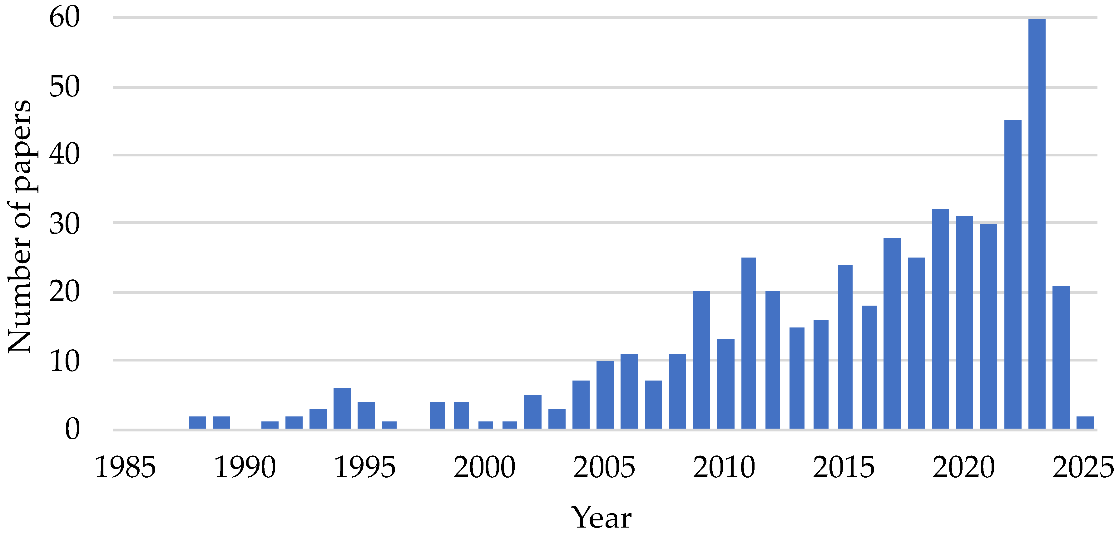
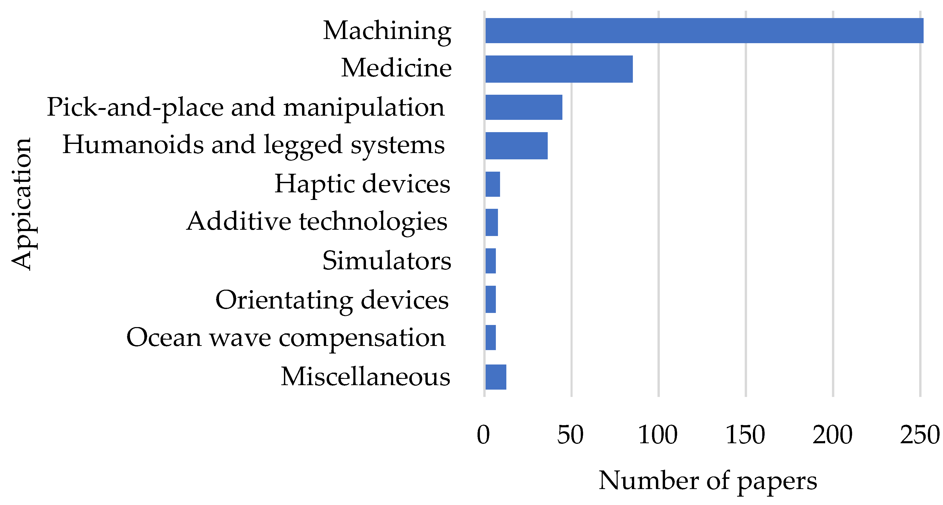
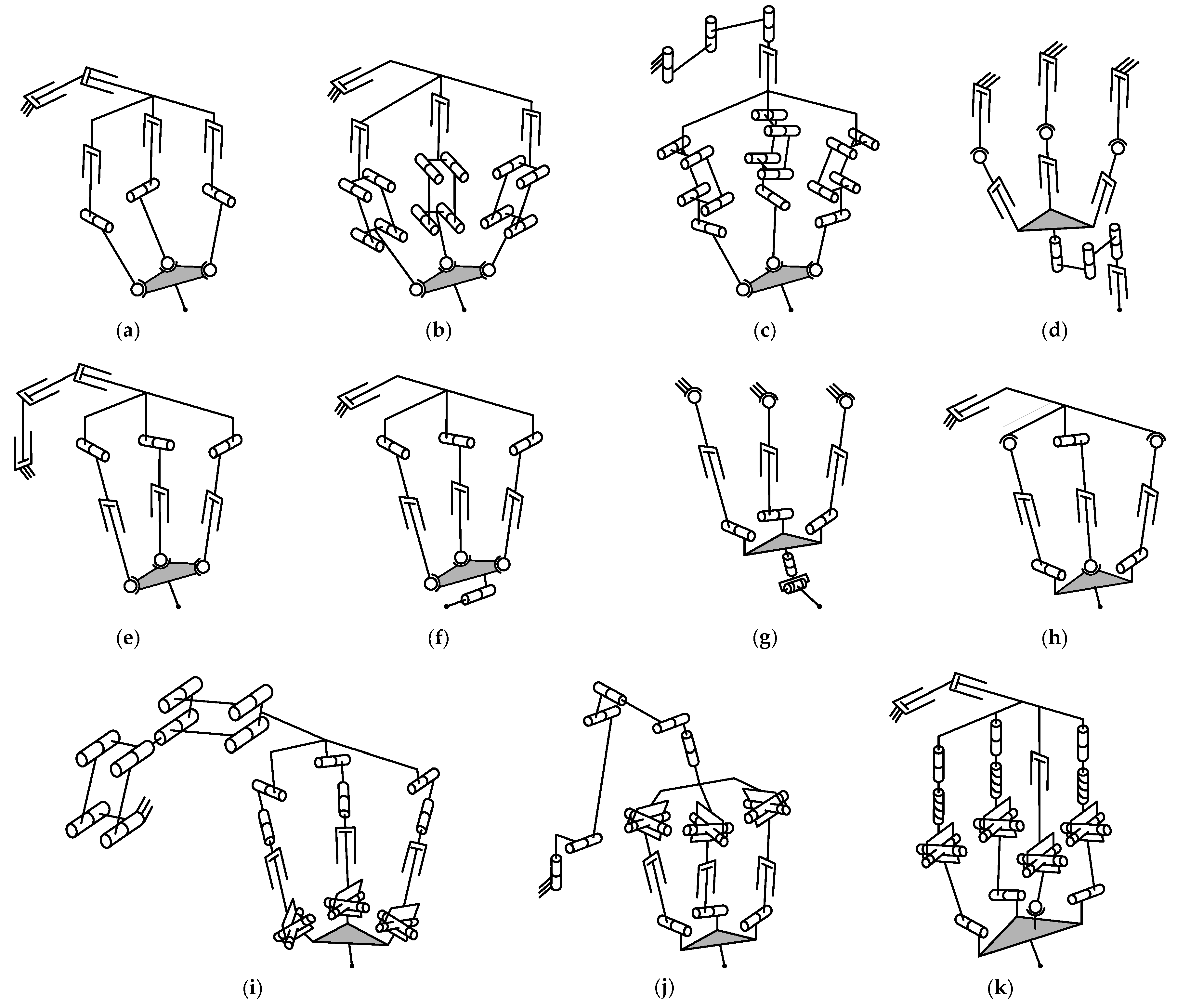
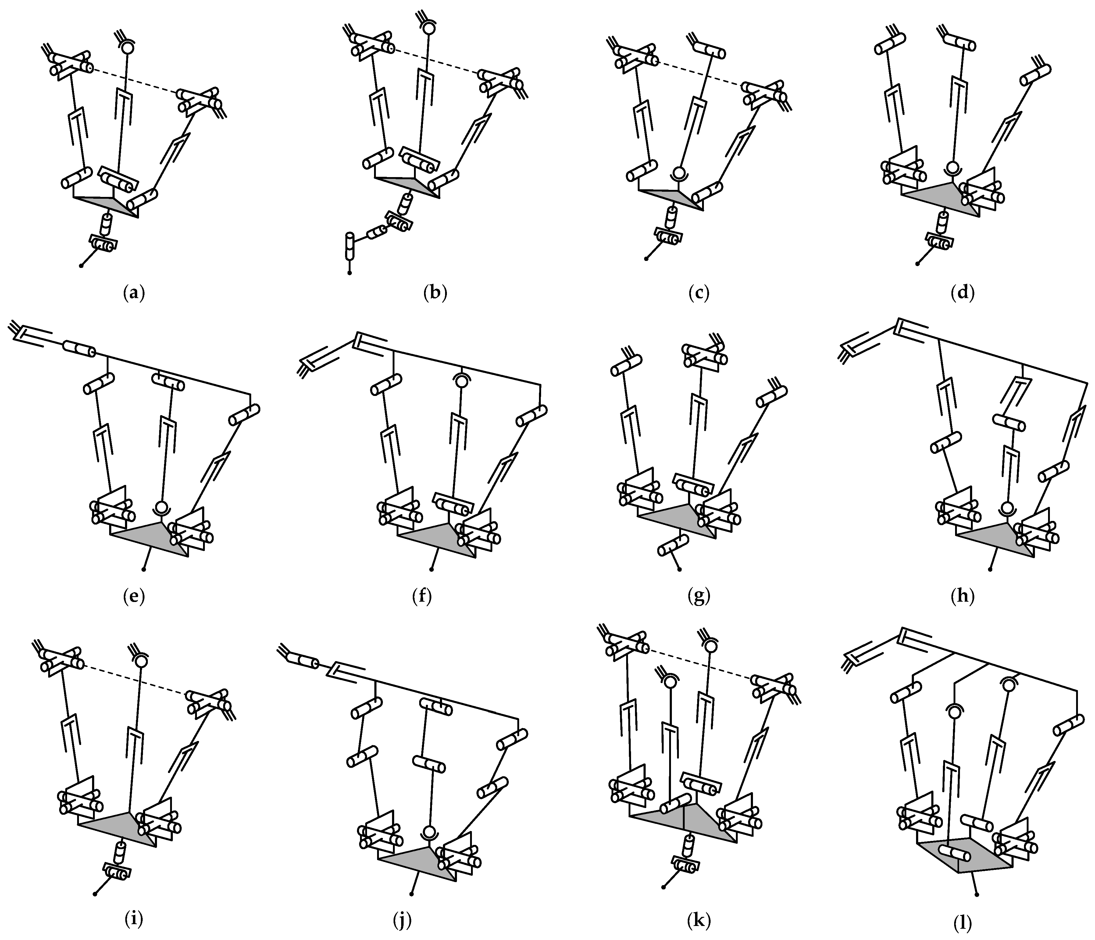
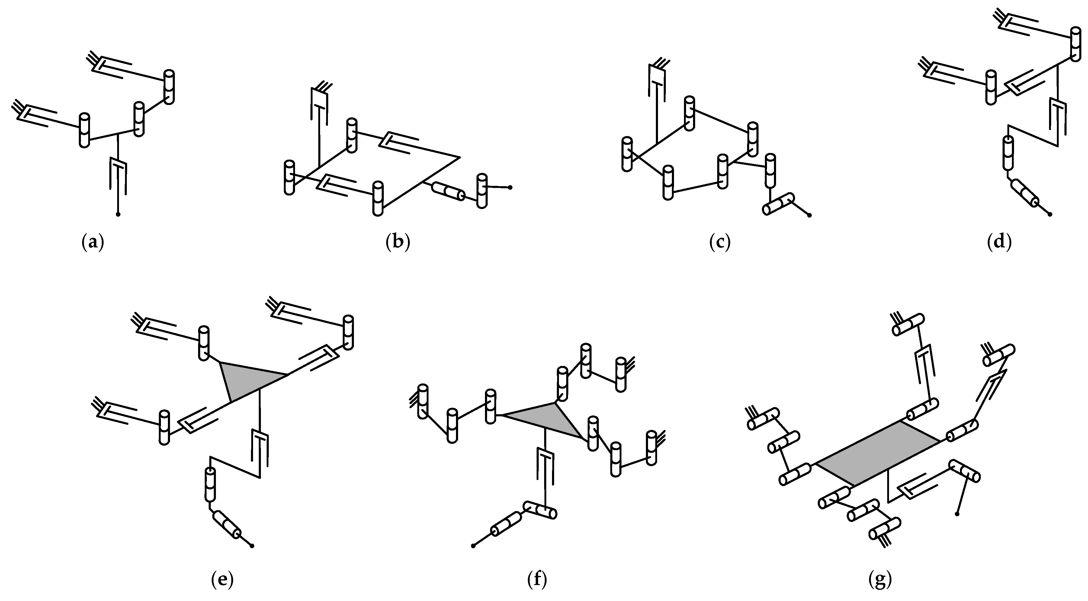
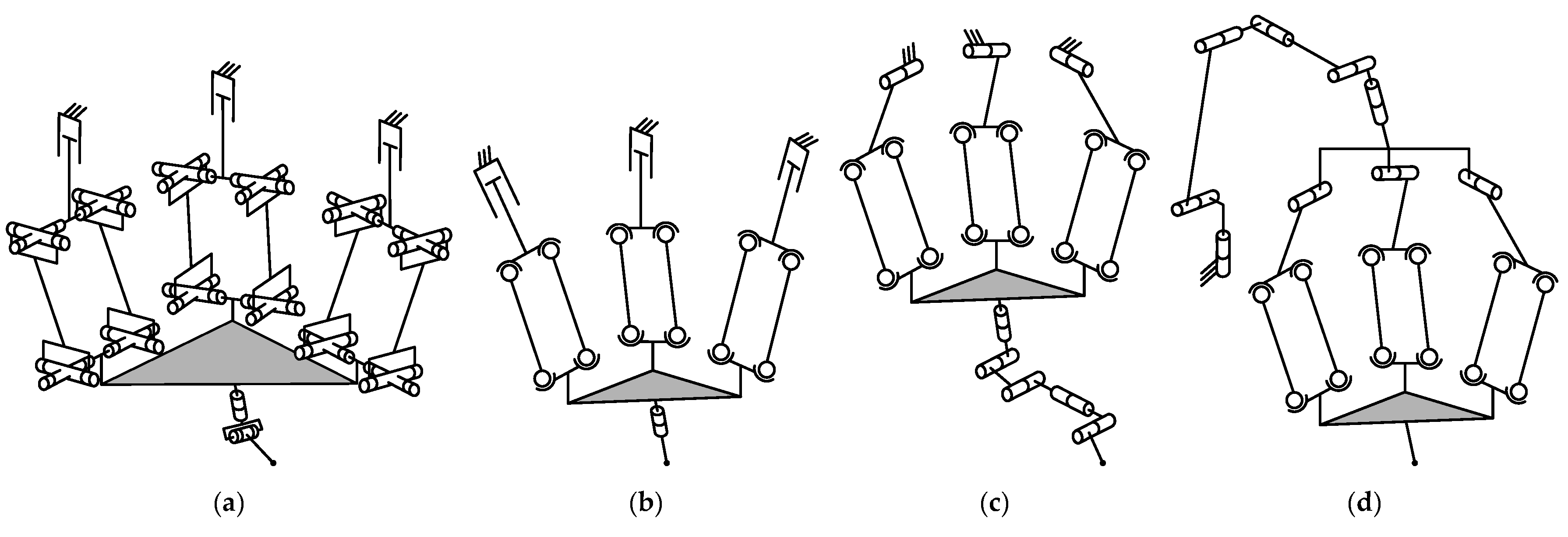
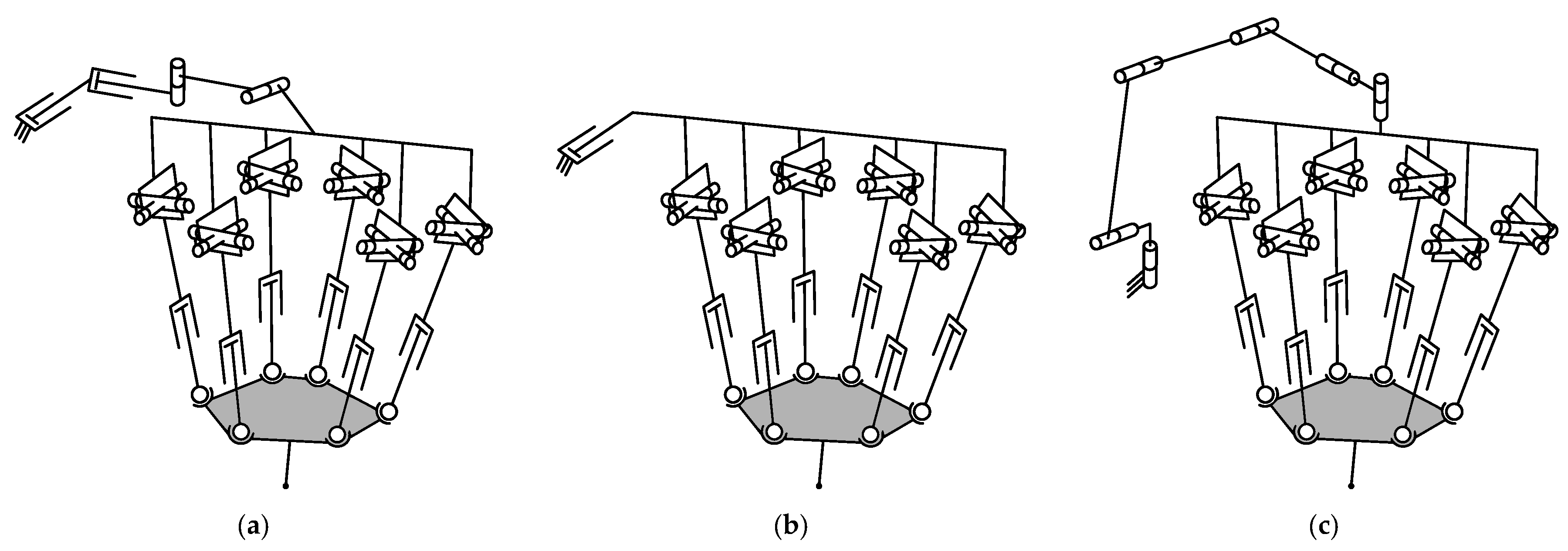
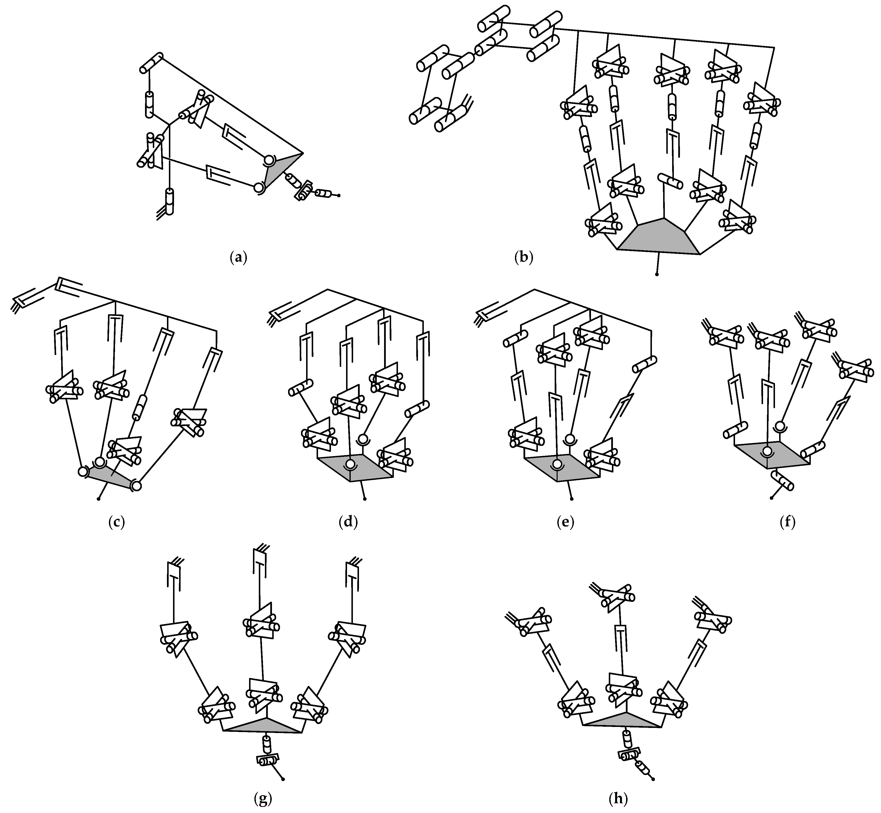
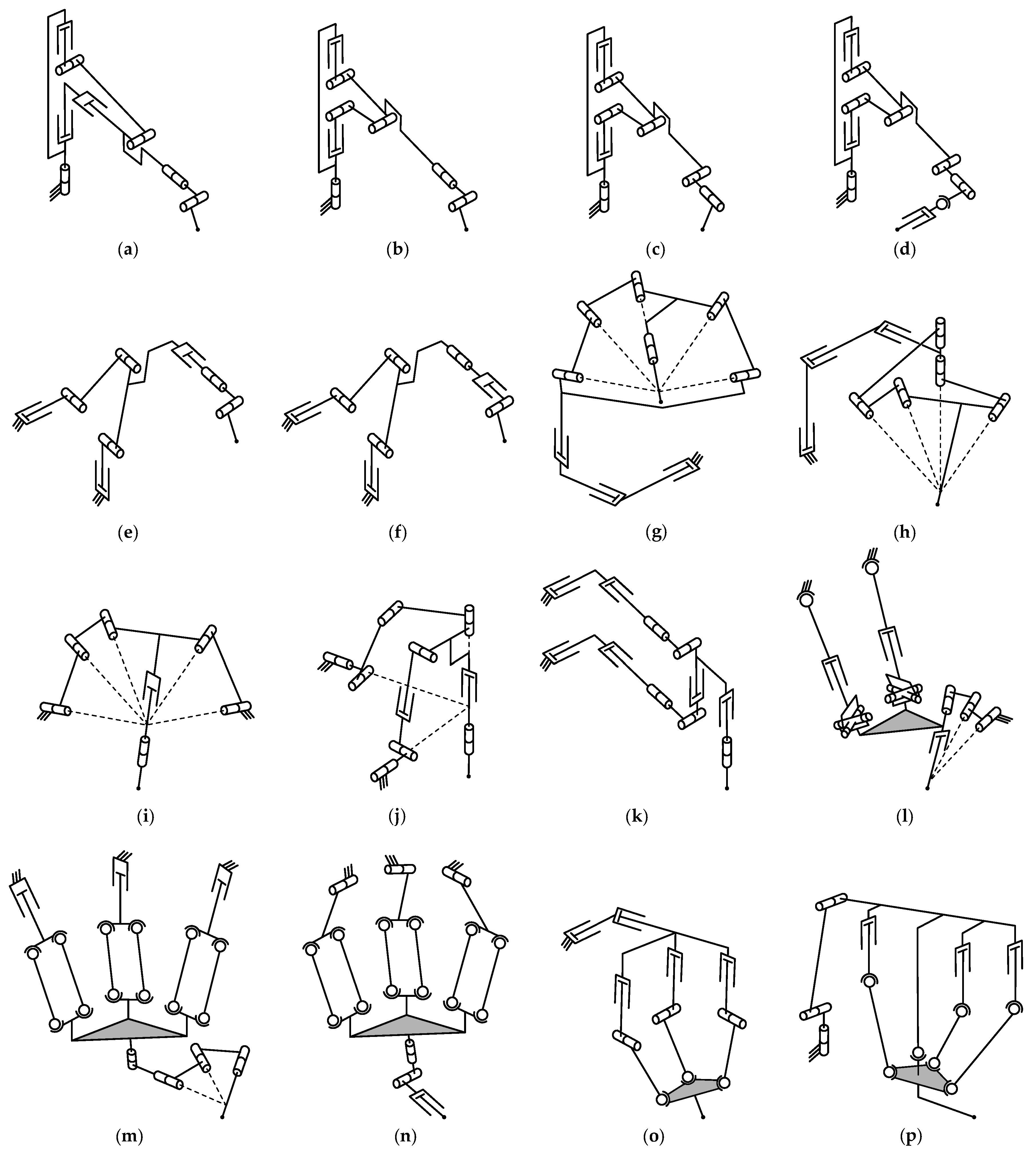
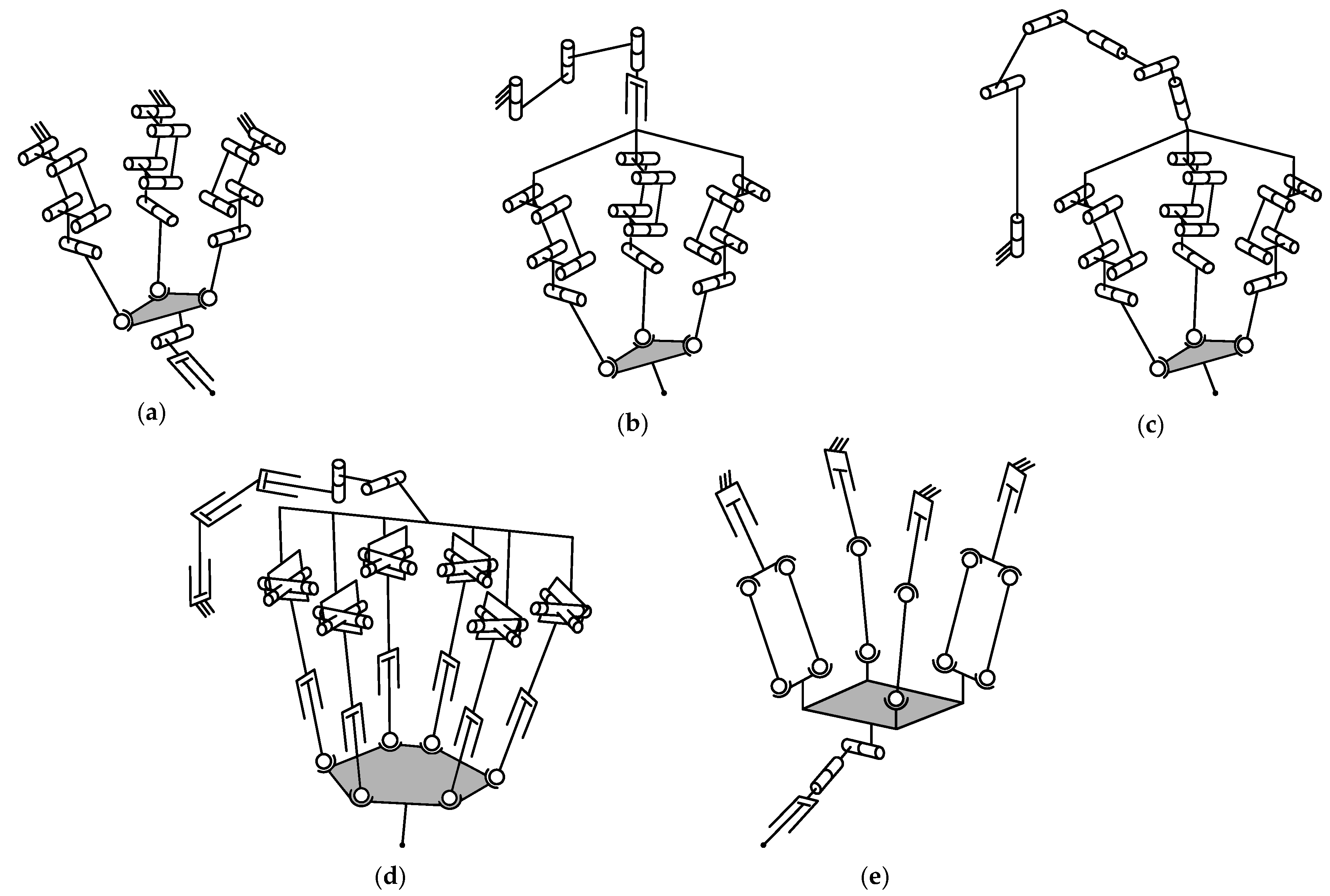
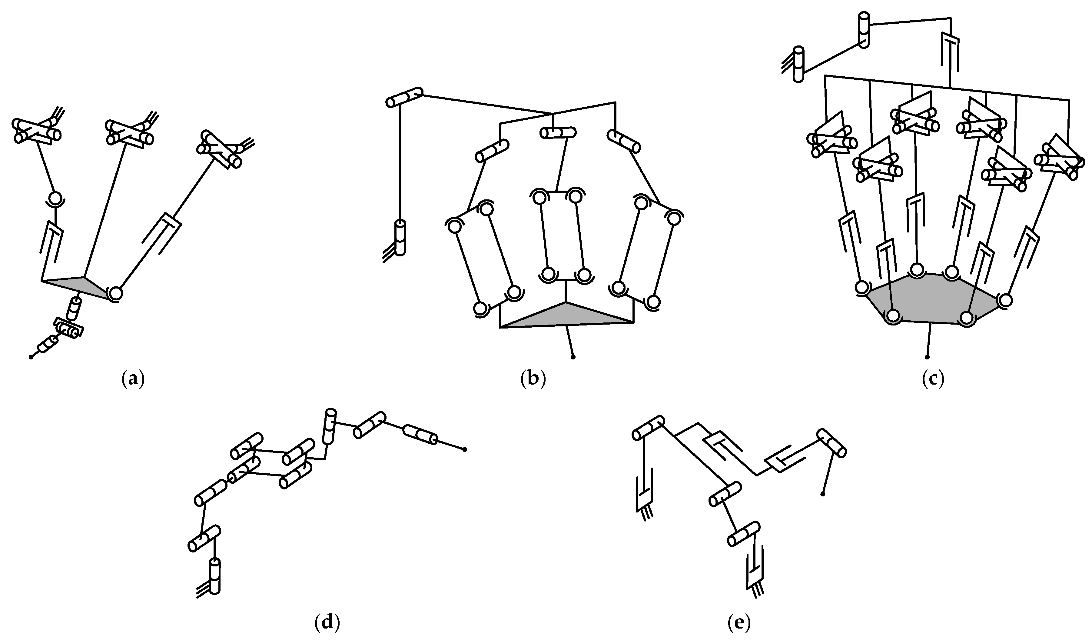
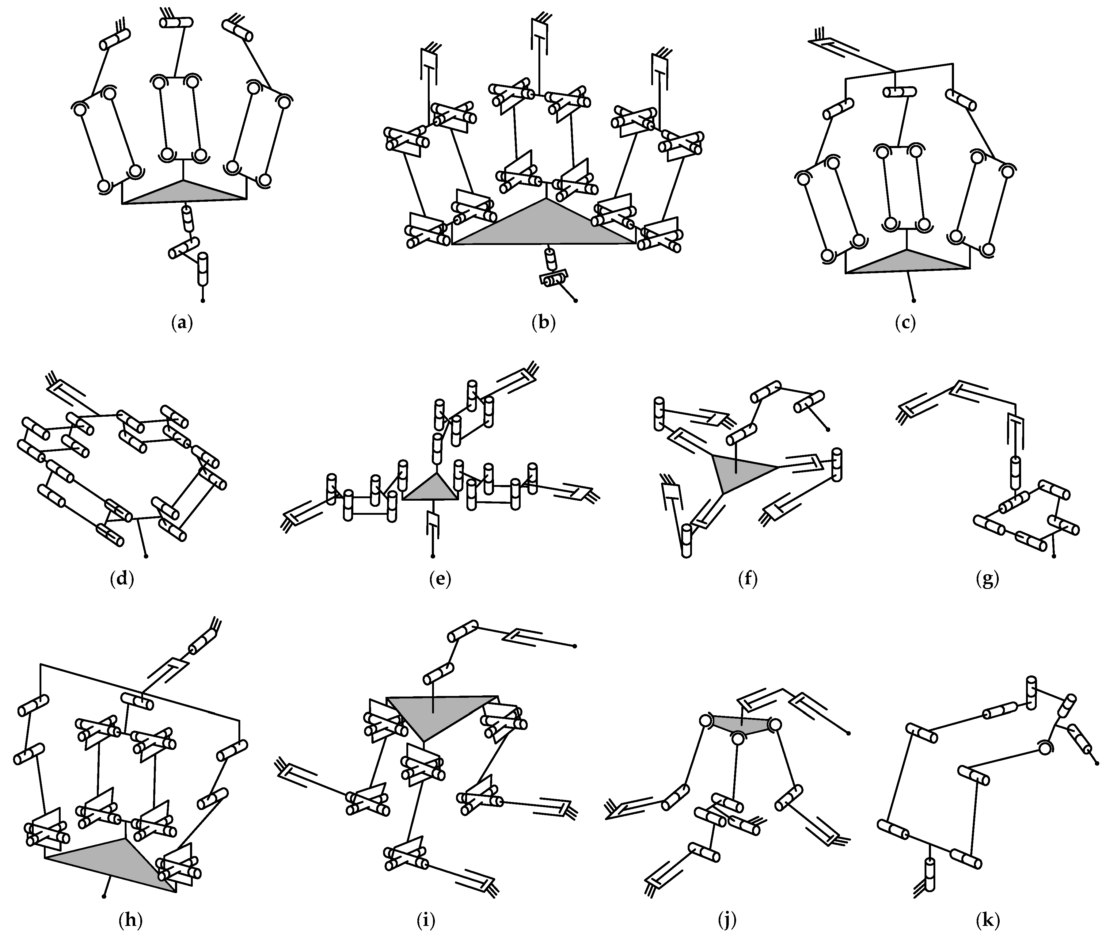
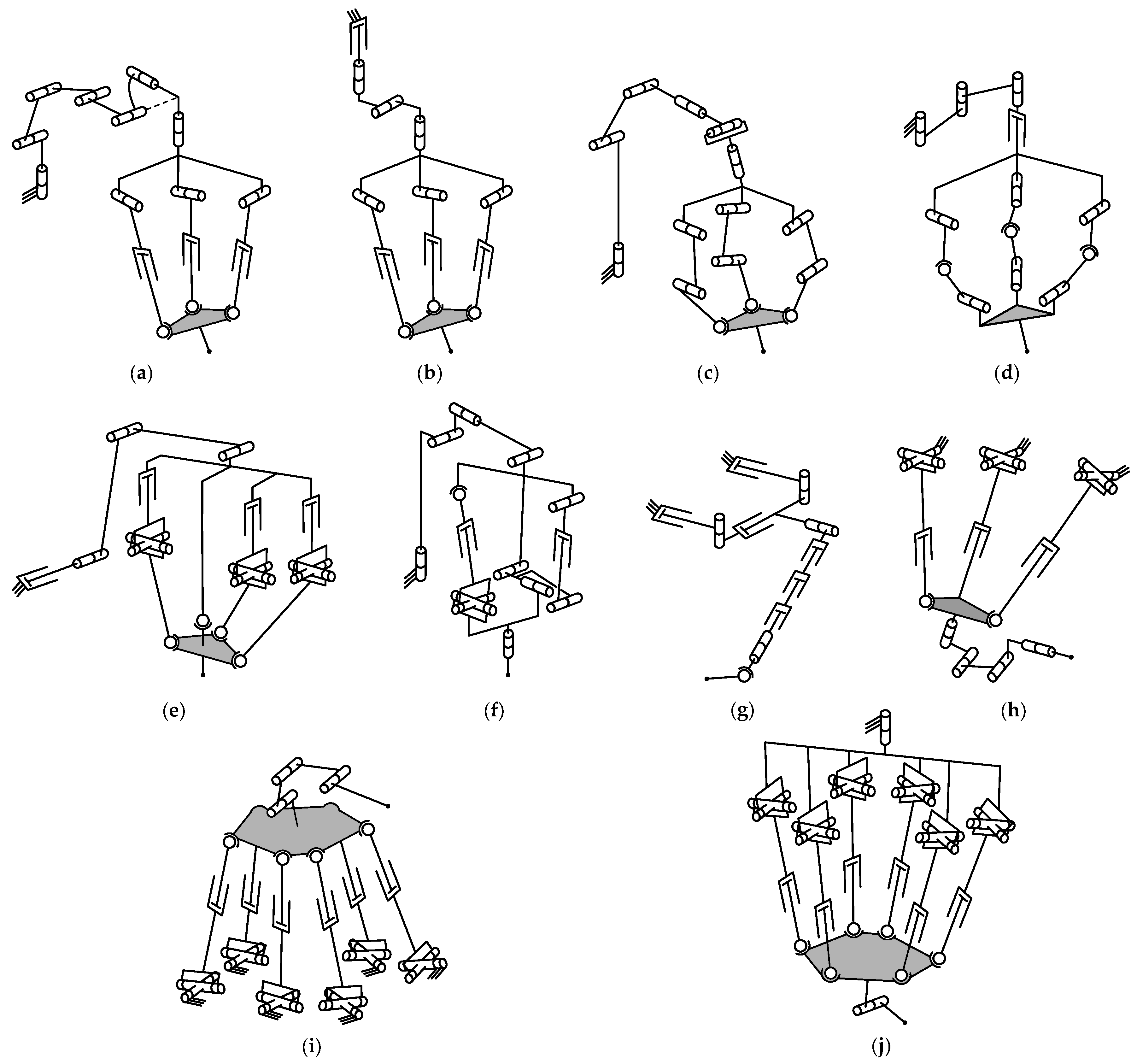
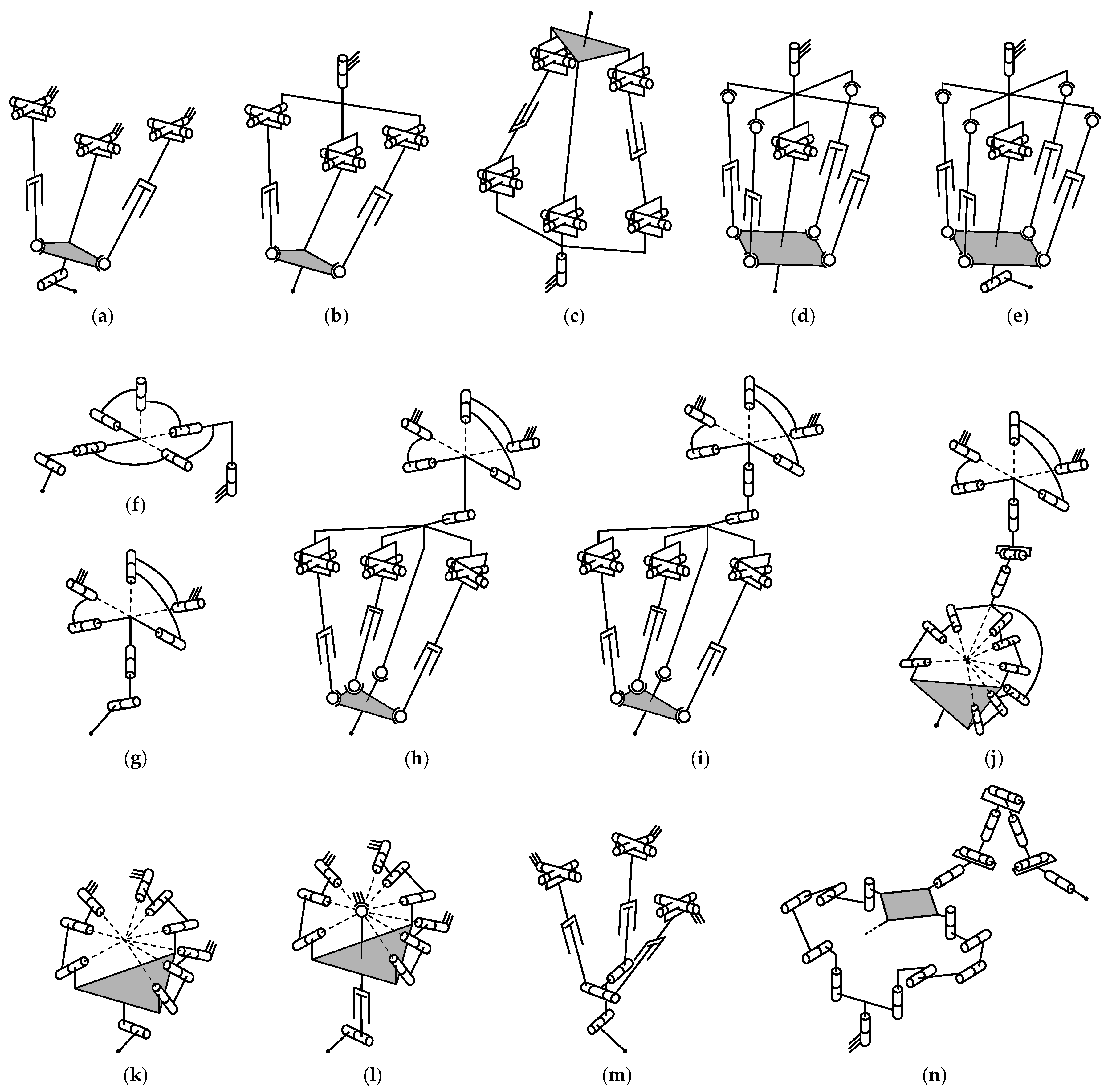
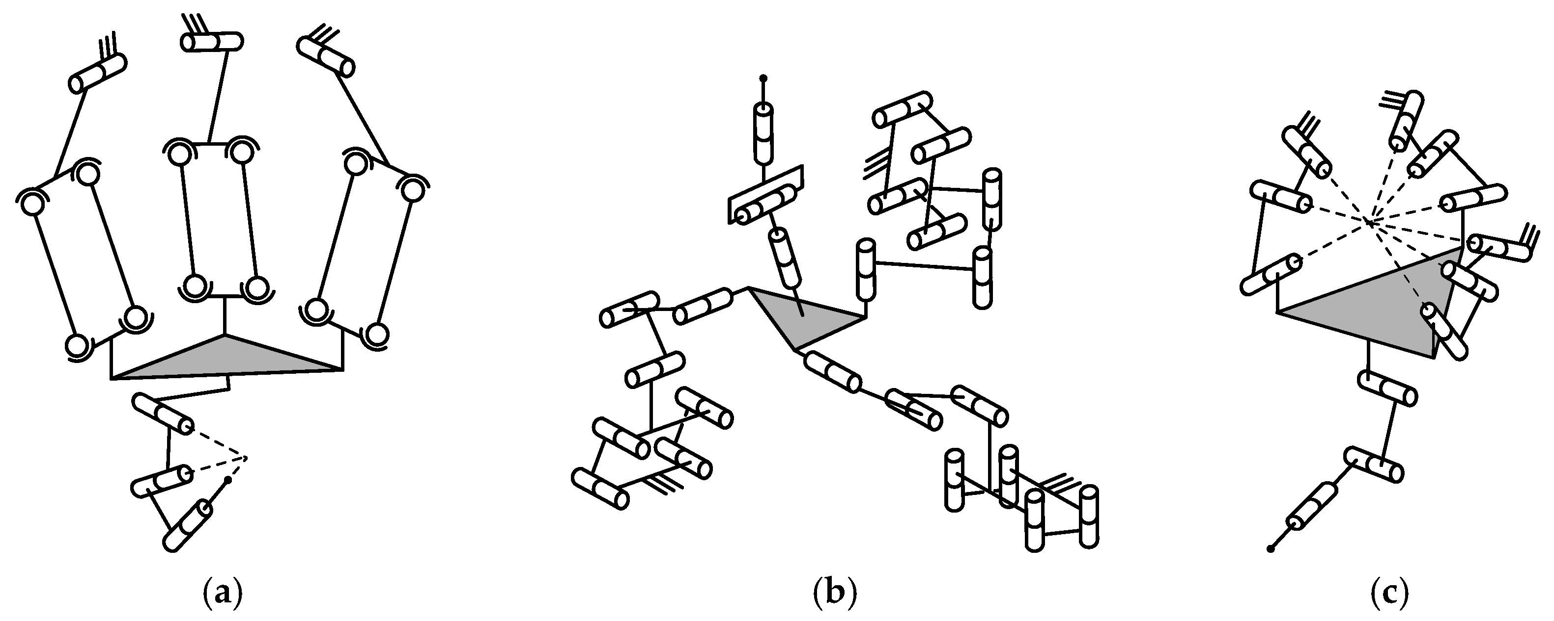

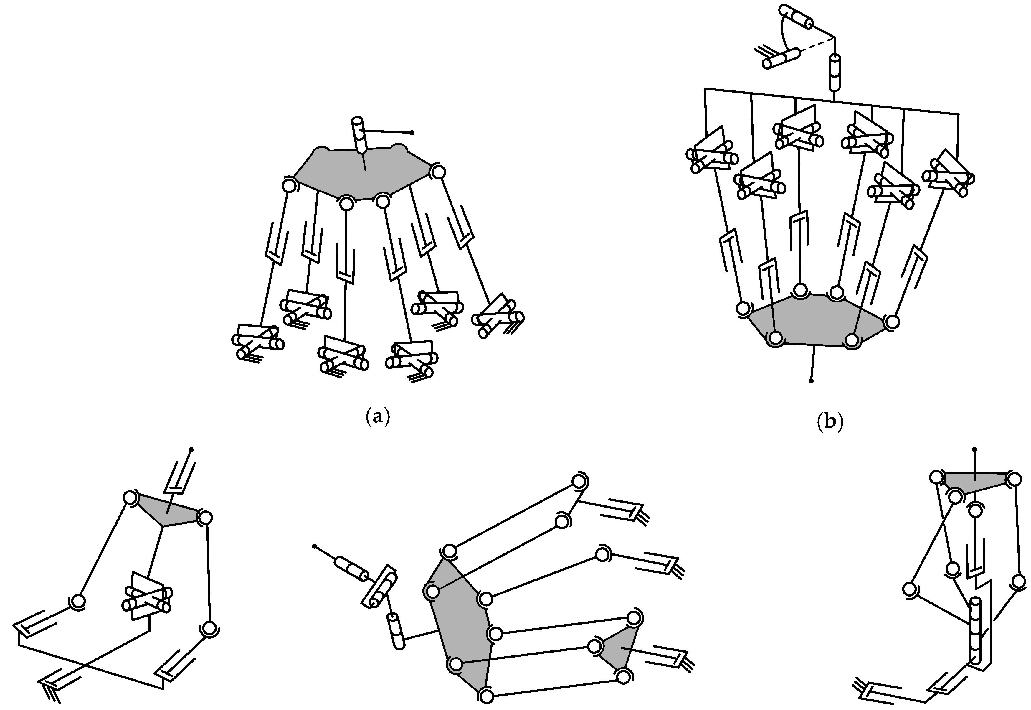


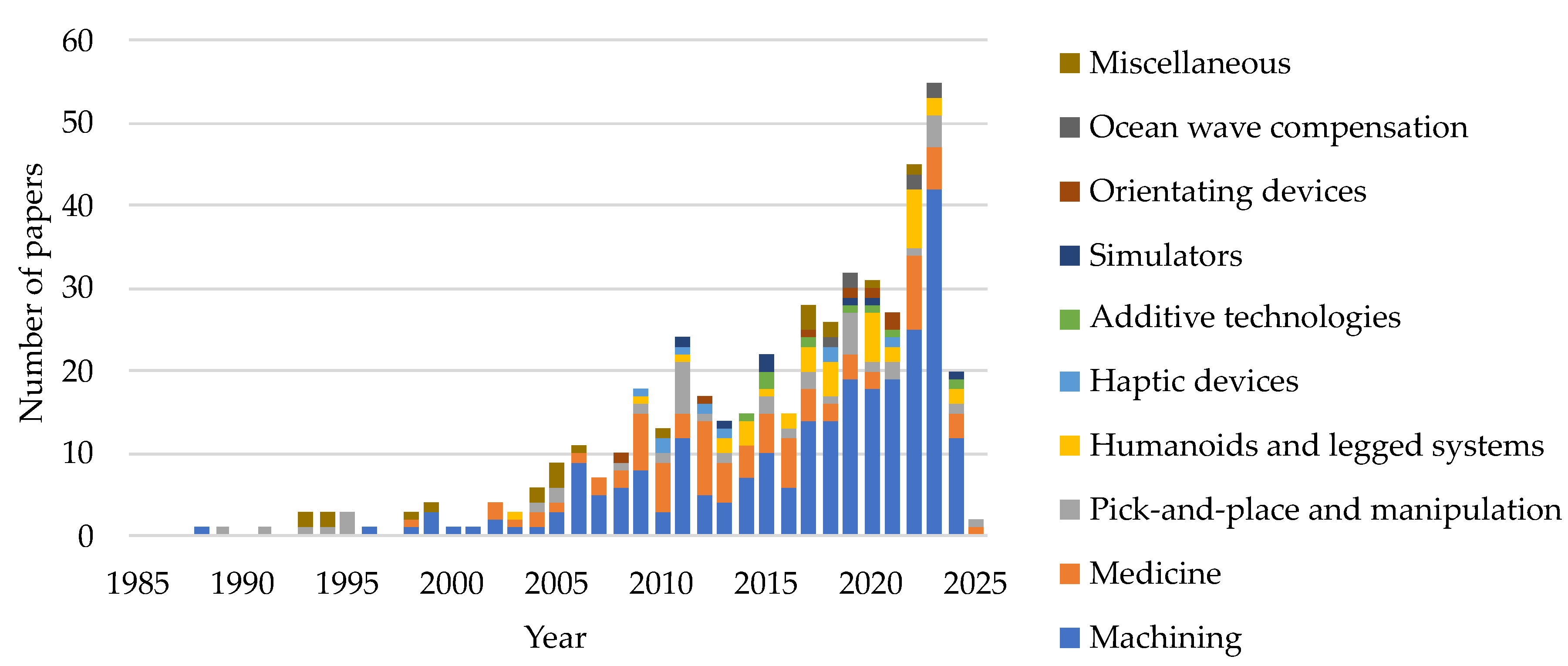

| Parallel part | Number of DOFs of a parallel-serial manipulator | Total | |||||||||
|---|---|---|---|---|---|---|---|---|---|---|---|
| motion type | 3 | 4 | 5 | 6 | 7 | 8 | 9 | 10 | 11 | 12 | |
| 1T | – | – | – | – | 1ME | – | – | – | – | – | 1 |
| 1R | – | – | – | 1PP | – | – | – | – | – | – | 1 |
| 1T1R | 1MA 1ME 1MS | 1MA | 4MA 5ME | – | – | – | 1ME | 1PP | – | – | 15 |
| 2T | – | 1PP | 1ME | – | – | – | – | – | – | – | 2 |
| 2R | 4HL 2OD | 3ME 3HL 1SM | 1MA 3ME 1MS | 1MA 1ME 1HL | 1PP 1HL | 1HL | – | – | – | – | 24 |
| 1T2R | – | 3MA 2ME 1HL 1OD | 27MA 2ME 1PP | 4MA 1OD 2OW 2MS | 3MA 1ME 3PP 1MS | – | 1MA 1ME 1PP | 1PP | – | – | 58 |
| 2T1R | – | 1PP 1MS | 1MA 1PP 1AT 1MS | 1MA 1PP | – | – | – | – | – | – | 8 |
| 3T | – | 1MA 1PP | 2MA 1ME 1PP 2AT | 1ME 2PP 2HD 1AT 1SM | 1ME | 1MA | 1MA | – | – | – | 18 |
| 3R | 1ME | 1HL | 1HL | 2ME 1HD | 1PP | – | – | – | – | – | 7 |
| 1T3R | – | – | – | – | 1MA 1SM | – | – | – | – | – | 2 |
| 2T2R | – | – | 3MA | 2ME 1MS | – | – | – | – | – | – | 6 |
| 3T1R | – | – | – | – | 1ME | – | – | – | – | – | 1 |
| 3T2R | – | – | – | – | 1MA | – | – | – | – | – | 1 |
| 3T3R | – | – | – | – | 1MA 1ME 1SM | 1PP | 1ME 1PP 1SM 1OW 2MS | 1MA 1ME | 1ME | 1MA 1ME | 15 |
| Total | 10 | 21 | 59 | 31 | 18 | 3 | 11 | 4 | 1 | 3 | 159 |
Disclaimer/Publisher’s Note: The statements, opinions and data contained in all publications are solely those of the individual author(s) and contributor(s) and not of MDPI and/or the editor(s). MDPI and/or the editor(s) disclaim responsibility for any injury to people or property resulting from any ideas, methods, instructions or products referred to in the content. |
© 2024 by the authors. Licensee MDPI, Basel, Switzerland. This article is an open access article distributed under the terms and conditions of the Creative Commons Attribution (CC BY) license (http://creativecommons.org/licenses/by/4.0/).

