Preprint
Review

Analysis of Cooling Methods to Improve the Electrical Performance of Photovoltaic Modules

Submitted:

25 October 2024

Posted:

29 October 2024

You are already at the latest version

Abstract
When solar energy is converted into electricity by photovoltaic modules, only 20% of the incident solar radiation is converted into electricity and the remaining 80% is converted into heat, increasing the temperature of the photovoltaic solar cells. The increase in PV module temperature has a negative impact on open-circuit voltage. This leads to a reduction in electrical efficiency and degradation of the photovoltaic modules. In order to maintain their operating temperature under standard test conditions, it is important to remove the excess heat from the photovoltaic solar cells by cooling. After cooling, the temperature of the PV modules decreases and the electrical efficiency is improved. In this article, air cooling techniques for photovoltaic modules are examined. The disadvantages and prospects of the different approaches to these air-cooling techniques are presented. Understanding the different cooling techniques is important for improving the electricity production of photovoltaic modules and for popularising this technology.
Keywords: 
Subject: 
Engineering  -   Energy and Fuel Technology

1. Introduction

Almost all countries in the world rely primarily on coal, oil and natural gas to meet their energy needs. Available in limited quantities, these conventional energy sources are running out at an accelerating rate. The massive use of fossil fuels has a harmful effect on the environment, such as global warming due to the release of carbon dioxide. To meet these energy needs and solve the environmental problem, renewable energies are now an alternative to fossil fuels [1,2]. Renewable energies have the potential to meet the world’s various energy needs and have no harmful impact on the environment. Among these renewable energy sources, solar energy has proved to be the most promising. Photovoltaic (PV) solar cells convert solar energy directly into electricity. PV solar cells are made of semiconductor materials, the main material being silicon [3]. Two forms of energy can be produced from solar energy, depending on the conversion technique used: electrical energy and thermal energy, using photovoltaic (PV) solar cells and solar thermal collectors respectively [4]. When solar radiation is absorbed by a PV module, the temperature of the PV solar cells increases, generating unwanted heat and thus decreasing their electrical efficiency [5,6]. PV modules become less efficient as the temperature increases; therefore, removing the heat from PV solar cells allows them to be cooled and makes the recovered heat useful for residential and industrial applications in many countries under varying climatic conditions [7,8]. This lowers the operating temperature of PV modules and improves their electrical efficiencies. In this paper, air cooling techniques for managing the operating temperature of PV modules have been reviewed. Various mechanisms for optimal heat extraction from PV modules have been presented. Finally, the drawbacks and prospects of the various air-cooling techniques are presented.

2. Factors Influencing the Electrical Performance of Photovoltaic Solar Modules

PV modules are spectrally selective absorbers that operate in a wavelength range of 0.35 μm to 1.2 μm and directly convert solar radiation into electricity [9]. The electrical efficiency of PV modules is therefore influenced by internal factors in PV solar cells and environmental factors. Factors such as PV solar cell temperature, solar irradiance, ambient temperature, air mass, humidity and dust affect the electrical performance of PV modules [10]. Solar irradiation and ambient temperature are factors that significantly affect the temperature of PV modules and therefore their electrical performance [11]. Figure 1 shows the current-voltage (I-V) curves of the PV module under different temperature and solar irradiance conditions.
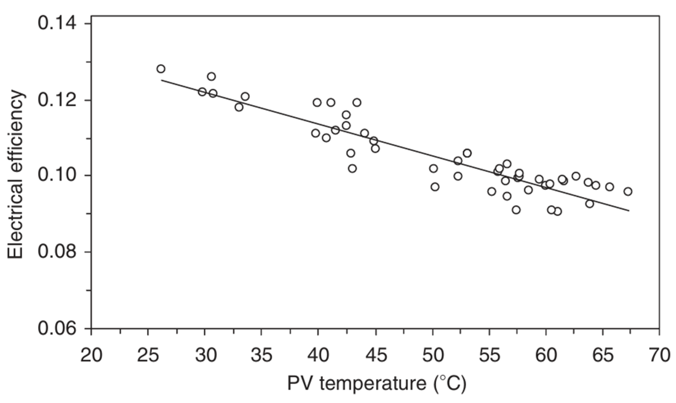
The electrical efficiency of a PV module is inversely proportional to its operating temperature. As the temperature of a PV module increases with solar irradiance, the electrical efficiency of the module decreases. This temperature is linear with respect to the ambient temperature and decreases exponentially with increasing wind speed [13]. The same authors [13] have also shown that dust deposited on the surface of a PV module increases the temperature of the PV module and consequently decreases its electrical power. In fact, the deposition of dust increases the temperature of the PV module by 6%. Figure 2 shows the electrical efficiency versus temperature curve for PV solar cells.
Consideration of the effect of wind in PV module temperature estimates and accurate knowledge of this behaviour is essential to optimise electricity production [15]. For example, high solar radiation contributes to heat dissipation from the solar PV module but increases its operating temperature [16]. In the presence of wind, the open-circuit voltage and maximum power at the point of maximum power are higher, while the short-circuit current is lower. When the PV module is tilted, the areas facing into the wind are cooled more [17]. A lower ambient temperature is useful both for heat dissipation and for improving the electrical efficiency of the PV module. Framed PV modules have a higher temperature gradient relative to their local temperature field than frameless glass PV modules. Framed PV modules facilitate more heat transport by conduction than by convection with ambient air, which is important for any solar power system [18]. The inclusion of PV module thermal inertia and wind speed in the temperature determination models resulted in a more accurate estimate of PV module temperature with 95% correlation and 3°C error [19].
The temperature distribution over the surface of PV modules depends largely on the geometry and material used in their design [20]. At high temperatures, amorphous silicon and copper-indium-gallium-selenide (CIGS) PV modules perform better than crystalline ones [21]. The power temperature coefficient depends on the PV solar cell technology used and therefore the electrical efficiency of the PV module depends on it. According to Dash and Gupta [22], the power temperature coefficient of monocrystalline silicon-based PV modules is higher than that of other types of PV modules, while cadmium telluride (CdTe)-based PV modules offer better electrical efficiency due to its low temperature coefficient. Indeed, for monocrystalline, polycrystalline, CdTe-based and amorphous silicon-based PV solar cells, the power temperature coefficient decreases by -0.446%/°C, -0.387%/°C, -0.172%/°C and 0.234%/°C respectively [22]. The temperature of thin-film PV modules is lower than that of other technologies, and the influence of ambient temperature on PV module temperature decreases in high wind conditions. The electrical efficiency of amorphous silicon PV modules is lower than that of multicrystalline PV modules in all wind conditions [23].

3. Need to Reduce the Temperature of Photovoltaic Solar Modules

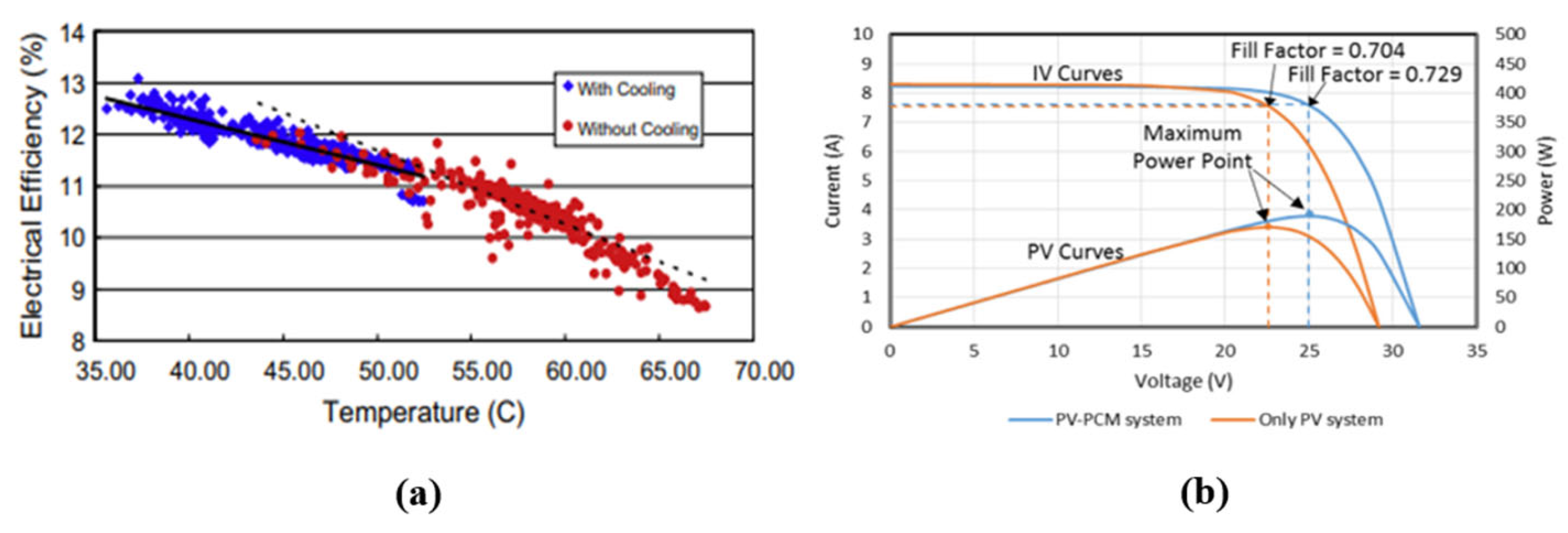
When converting solar energy into electricity, only 20% of the solar radiation incident on the surface of the PV module is converted into electricity and the remaining 80% is converted into heat [3]. The efficiency of PV modules is thus severely affected by the increase in temperature. The electrical performance of the PV module can be improved by lowering the operating temperature of the PV solar cells. For this purpose, several cooling means are used to regulate the temperature of the PV modules. Most of these cooling techniques were reviewed by J. Paul et al. [24]. There are active cooling methods and passive cooling methods. Passive cooling, which does not require external power, consists of natural air circulation using phase-change materials, fin heat sink cooling and radiative and photonic cooling [25]. There is also thermoelectric cooling and cooling by integrating PV modules into buildings. Active cooling is the circulation of forced air in an air duct to increase the rate of heat transfer. To enhance cooling, artificial roughness such as baffles, ribs etc. are added in the air duct. Active cooling results in higher electrical efficiency but requires power supply which is more expensive than passive cooling [26]. Teo et al. [26] experimentally actively cooled the PV modules and obtained a linear curve between the electrical efficiency and the temperature of the PV modules, as shown in Figure 3 (a). Without active cooling, they showed that the PV module temperature was high with an electrical efficiency of 8-9%. When the PV module operates in an active cooling condition, its temperature decreases; this leads to an increase in the electrical efficiency of the PV module of 12% to 14% [26]. Another experimental study by Rahman et al [10] shows that at 1000 W/m² without cooling, the PV module temperature increases by 56 °C, the electrical power decreases by 20.47 W and the electrical efficiency decreases by 3.13%. According to the same authors, reducing the PV module temperature by 22.4 °C increases the electrical power by 8.04 W and the electrical efficiency by 1.23% with cooling. Figure 3 (b) shows the effect of cooling with the phase-change material (PCM) and not cooling the PV module.

4. Methods of Cooling Photovoltaic Modules

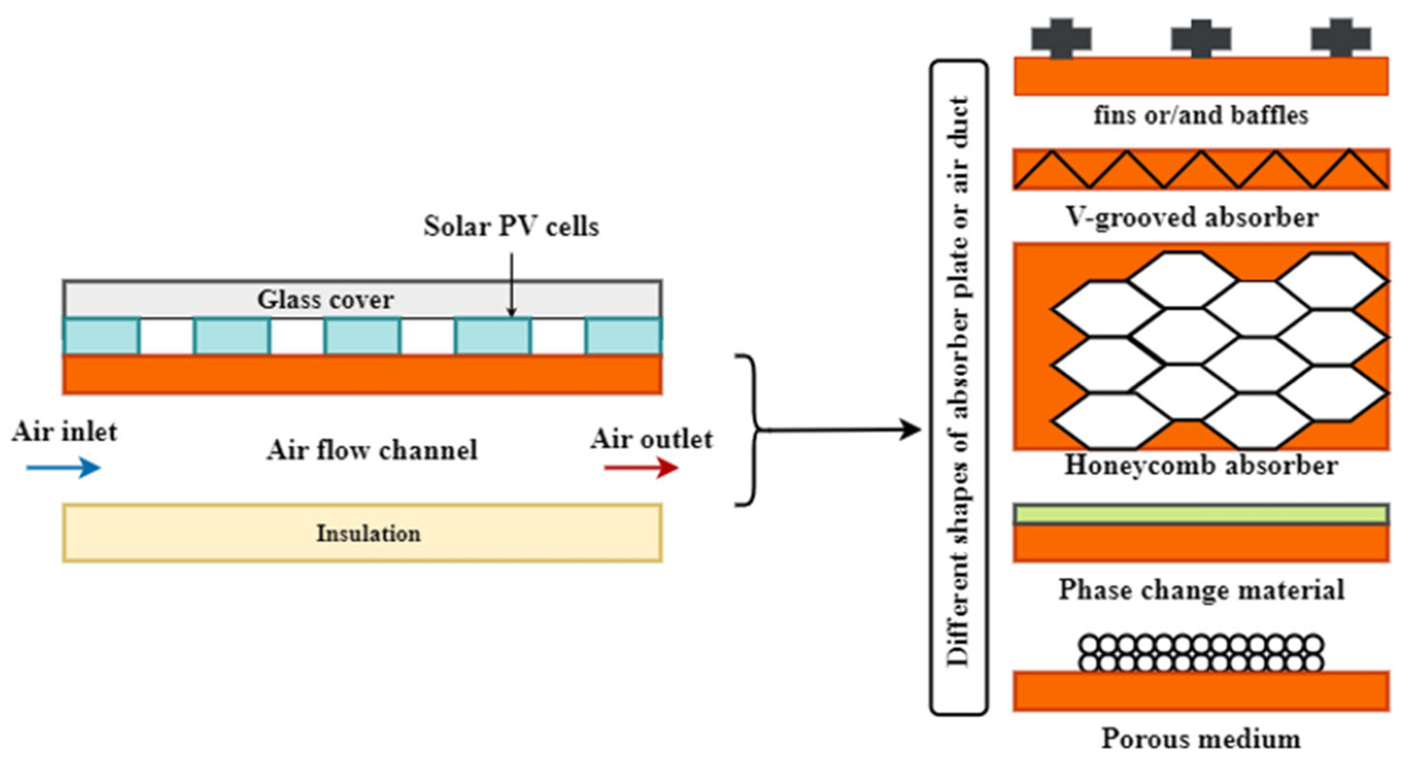
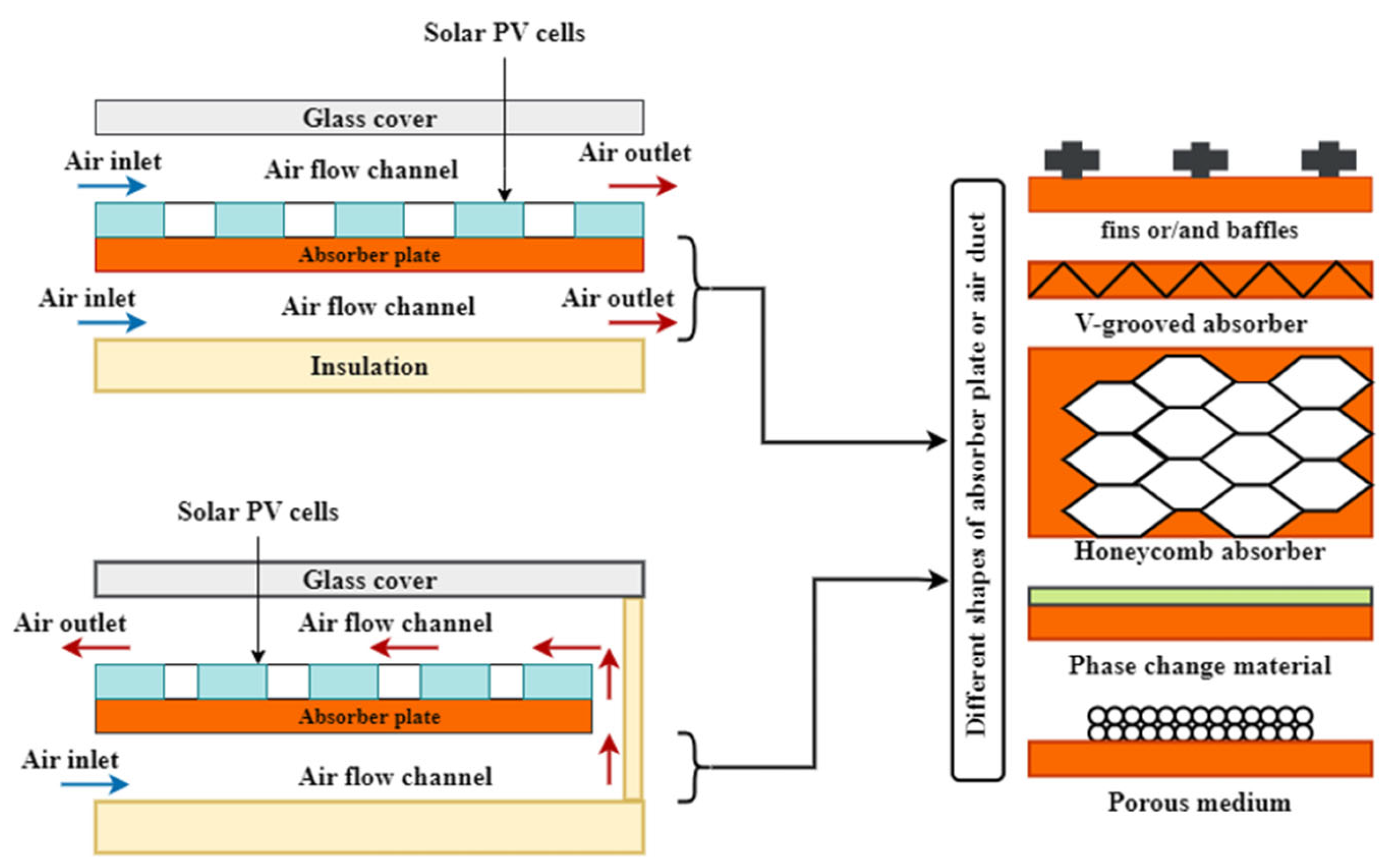
The various configurations of single-pass and double-pass air-cooled PVT plate hybrid solar collectors with their enhancement techniques are illustrated in Figure 4 and Figure 5.

4.1. Cooling of Photovoltaic Modules by Natural Air Convection

The natural mechanisms of heat transfer between the PV module and the ambient environment are highlighted in a natural air circulation cooling. This is the conduction, convection and radiation to dissipate heat from the PV module without the intervention of an external energy source. The passive cooling of the PV module studied by a simulation of the three-dimensional fluid dynamics of the natural air circulation and heat transfer showed that by increasing the angle of inclination of the PV module at wind speed above 1 m/s, the average temperature of the PV module increases by about 4 K but its electrical efficiency decreases.
Under transient conditions, the free convection currents in the tilted and horizontal positions of the PV module are lower compared to those in their vertical position [29]. In addition, increasing the length of the PV module up to 1.3 m in a tilted position improves the heat transfer rate [29]. However, beyond this length, the temperature of the PV module becomes high and the convective heat transfer coefficients are reduced regardless of the inclination [29]. In the horizontal position, the convective heat transfer rate is lower, especially on the lower surface of the PV module [29]. Radiation, free convection and forced convection heat transfer mechanisms are involved in the dissipation of thermal energy generated on PV module surfaces to the surrounding environment [30]. The same authors developed a model that incorporates a forced convection control coefficient to track the effect of the PV module tilt angle on the forced convection heat transfer mechanism. The results obtained showed that the model is capable of estimating the temperature of the PV module with an error of 0.927 °C and a correlation of 0.997 under the environmental conditions considered [30].

4.2. Cooling PV Modules with Finned Heat Sinks

A heat sink is a device that absorbs and transfers heat from an object through thermal contact. Heat is dissipated by the ambient air, the drawn-in air column or the coolant. Heat sinks are devices with fins, made of a good thermal conductor such as copper and aluminum alloy. The surface of the heat sink must be smooth and flat to minimize thermal resistance with the object being cooled. The use of fin heat sinks as cooling technique promotes a natural convection heat transfer resulting in better cooling rate by reducing the temperature of PV modules [25]. Thus, the passive cooling approach consists of attaching rectangular aluminum fins to the back surface of the tedlar layer. According to Emy Zairah Ahmad et al. [25], there was a reduction in the temperature of the PV module with fins of 3.25 °C compared to a module without fins. As a result, the heat sinks improved electrical power by up to 14.2%. The maximum voltage of the PV module increased from 17.2 V to 20.4 V when fins are added while the fill factor increased from 0.744 to 0.826.
The temperature reduction of PV modules using air-cooled heat sinks has been studied numerically by Popovici et al. [28]. The heat sink was designed as a ribbed wall made of a material with high thermal conductivity. Using ANSYS-fluent software for turbulent flow, the results showed that the increase in electrical power produced by a PV module with ribs is 6.97% to 7.55% for angles of 90° to 45°, respectively. The same authors [28] also showed that the cooling of the PV module is directly proportional to the height of the ribs and inversely proportional to their angles of inclination. Hudişteanu et al. [29] evaluated the passive cooling of PV modules through perforated and non-perforated heat sinks. The PV module was tilted at an angle of 45° to the horizontal with the wind direction to the rear. The greatest cooling effect was achieved under low wind conditions and high levels of solar radiation. For a wind speed of 1 m/s, a solar irradiance of 1000 W/m² and an ambient temperature of 35°C, the electricity production of the PV module without cooling reached 83.33%, while when the PV module was cooled, the electricity production reached 88.74%, resulting in a 6.49% increase in electricity. When the tedlar layer of a PV module was replaced with an aluminum alloy micro-fins heat sink, the temperature of the PV module was reduced by 14.65% and the improvement in electrical performance was 13% for electrical power and 13.32% for electrical efficiency [30]. The daily average was 11.02% for electrical efficiency, 40.94% for thermal efficiency and 51.9% for overall efficiency.

4.3. Cooling of Photovoltaic Modules by Forced Air Circulation

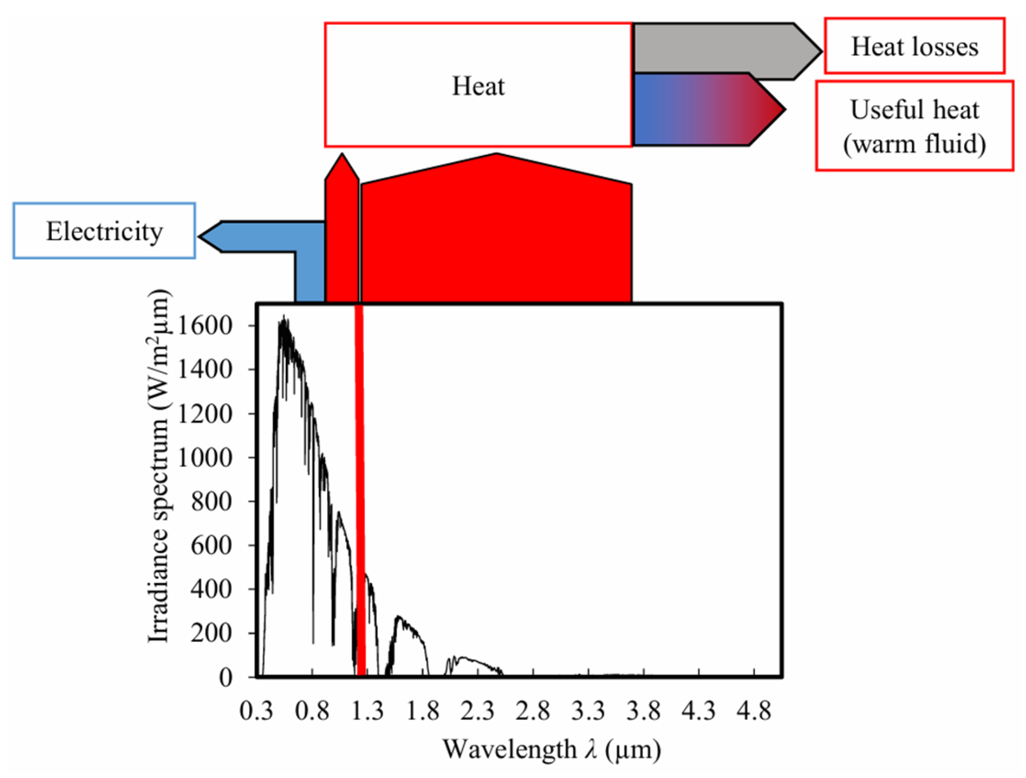
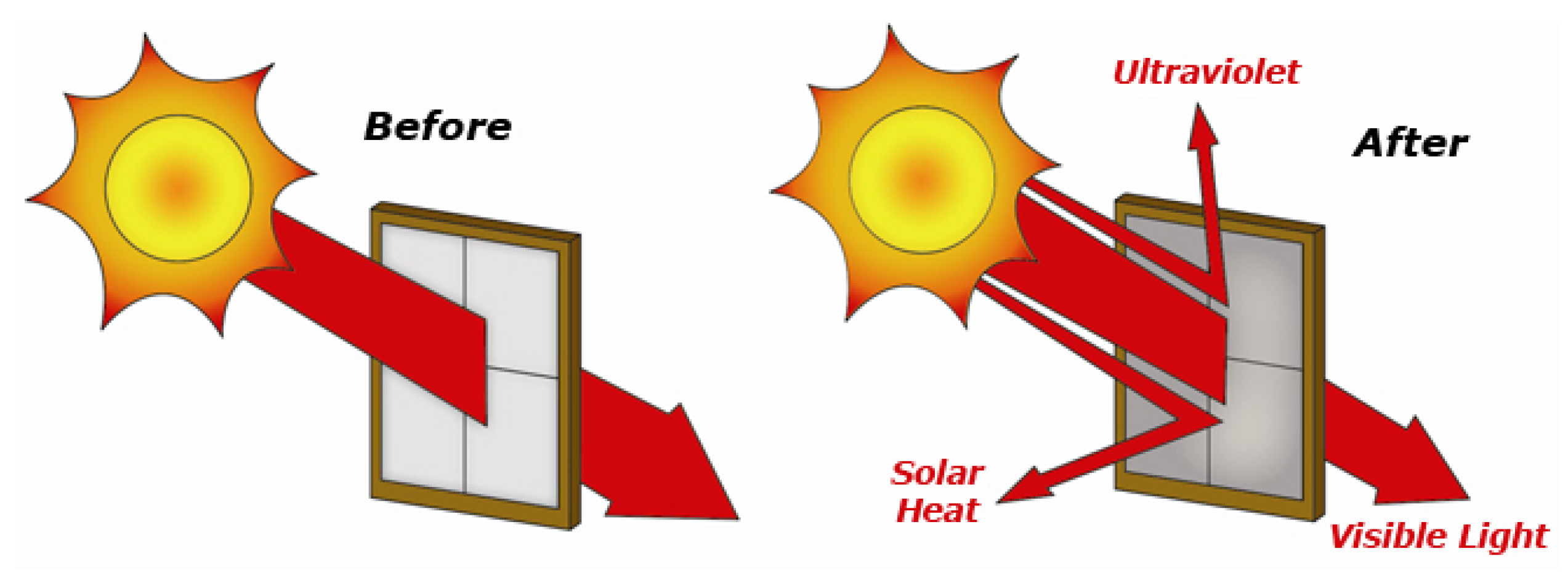
The visible and ultraviolet light spectrum is transferred to the PV solar cells and converted into electricity. The rest of the infrared light spectrum, which represents about half of the light spectrum, heats up the PV solar cells and thus reduces their electrical efficiency. Thus, the idea behind the design of hybrid photovoltaic/thermal (PVT) solar collectors is to better exploit unwanted heat into useful heat (Figure 6) [9]. As a result, PVT hybrid solar collectors can achieve higher overall efficiency than PV solar modules or thermal solar collectors alone [34,35]. The various PVT hybrid collectors design technologies are reviewed in several articles [36,37,38].
The PVT hybrid air collector is one of the most widely used PV module cooling technologies in recent years. The forced circulation of air through an air duct cools the PV solar cells so that the air leaving the PV module can be used for domestic and industrial applications. The PVT hybrid collector can decrease, optimise and control the temperature of the PV module, improve electrical efficiency, save installation space for the consumer and increase surface shading during times of high sunlight, thus reducing the thermal load on the system [39]. A study by Ranganathan et al. [40] shows that the maximum temperatures of the top glass, PV solar cells, Tedlar and air at the air duct outlet are 56.06°C, 59.44°C and 45.48°C respectively.
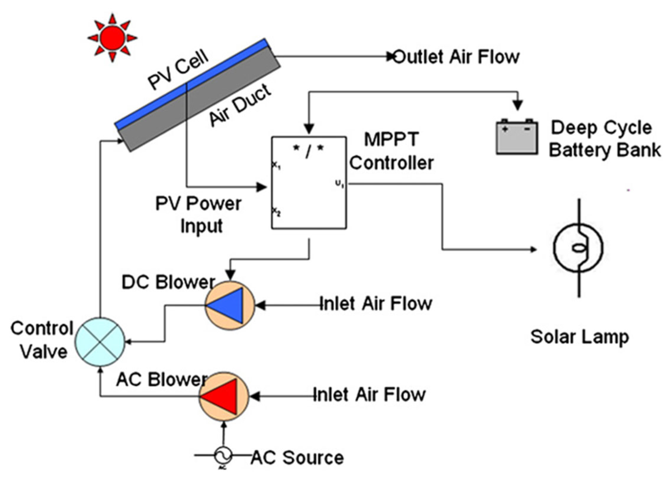
Srimanickam et al. [41] have shown that as the air mass flow rate increases, the efficiency of the PVT collector also increases. This means that the air mass flow rate helps to extract more thermal energy from the backside of the PV module and maintain its electrical efficiency. A comparative study of the performance of four different air-hybrid solar collector configurations under the same climatic conditions shows that the electrical efficiency increased from 9.8 to 12.9% for an air mass flow rate of 0.00847 kg/s and from 10.3 to 13.9% for an air mass flow rate of 0.0113 kg/s [42]. Omer and Zala [43] show experimentally that the electrical efficiency and thermal efficiency of the PVT hybrid collector increase by 20% and 44% respectively when the air flow rate is increased from 0.024 to 0.057 m3/s. An experimental study by Kim et al. [44] shows that the PVT hybrid collector fitted with a heat recovery ventilator has an overall efficiency of 38%. To investigate the effect of corona wind from an electro-hydrodynamics study, an experimental study by Golzari et al [45] showed that corona wind increases the heat transfer coefficient by 65% in the natural flow regime by producing a secondary flow and vortex, and consequently increases the efficiency of the once-through air PVT collector. Another experimental study by Golzari et al. [45] improves heat transfer by electro-hydrodynamics (corona wind effects) through a PVT hybrid once-through air collector. The results show that corona wind is effective in improving the performance of the PVT hybrid collector with an increase in the heat transfer coefficient of 65% in the natural flow regime. Active cooling of PV modules for different PVT hybrid collectors was performed by Ceylan et al. [46]. The electrical efficiencies of PV modules with cooling were about 13% and the electrical efficiencies of PV modules without cooling were about 10%. A comparative study carried out on a conventional PV module and a PVT hybrid once-through air collector shows the effect of cooling on improving electrical and thermal efficiencies, with up to 44% compared to the PV module without active cooling [47]. Teo et al. [26] conducted an experimental study on active cooling of the PV module using a DC fan (Figure 7).
According to this study, the electrical efficiency of the PV module increases with the mass flow rate up to 0.055 kg/s and remains almost constant above that [24]. Lyes et al. [48] analyzed the effect of mass flow rate and air channel depth on the efficiency of a PVT hybrid air collector. The results showed that the overall efficiency of the PVT-air hybrid collector increases from 60% to 75% and that the mass flow rate required to maintain the PV cells at a constant temperature decreases from 1.8 to 1.2 kg/s for an exchanger channel depth varying from 0.35 m to 0.05 m. They also found that the overall conversion efficiency of the PVT hybrid collector increases from 25% to 60% and the temperature of the PV solar cells decreases from 345 K to 335 K as the mass flow rate increases from 0.02 kg/s to 0.1 kg/s. For a flow rate of 0.0016 kg/s, an irradiation of 1000 W/m² and an ambient temperature of 20.15°C, the fluid outlet temperature reaches 55.96°C [49]. The same authors also showed that the temperature of PV solar cells decreases and reaches 23.845 °C with increasing mass flow rate up to 0.0256 kg/s; the electrical power reaches 59.434 W at the same flow rate. A Computational Fluid Dynamics (CFD) study of a PV module with and without cooling shows that the temperature reached by an uncooled PV module is 74.87 °C [50] with an electrical power drop of 0.113 %. For a cooled PV module, its temperature is maintained at 45.9°C and its electrical power at 1.4W. In addition, an optimum flow velocity of 0.5 m/s is achieved to absorb the maximum amount of heat from the PV module. When the flow velocity exceeds this value, the electrical energy is no longer affected [50].
The effect of high solar radiation using a concentrator significantly improves the electrical efficiency of the PV module. For irradiance ranging from 1000 to 5000 W/m² with an optimized flow rate of 180 L/h, the electrical and thermal energies of the PVT hybrid concentrator increased from 197 to 983W and from 1165 to 5387W, respectively. The electrical, thermal and overall efficiency reached 10.6%, 71% and 81.6%, respectively, for an irradiation of 5000 W/m² [51]. At an irradiation of 3000 W/m², the electrical power of a concentrating PV module increases by 190W compared with 63W at an irradiation of 1000 W/m². In addition, the electrical power and thermal energy increase by around 6.4 and 31.3W, respectively, for each 100 W/m² increase in solar irradiation [52].

4.4. Cooling Photovoltaic Modules Using Artificial Roughness

Optimum heat extraction from PV solar cells is achieved by adding artificial roughness or obstacles behind the PV module. Fixing obstacles in the air duct increases the heat transfer coefficient between the circulating air and the absorber of a PVT hybrid collector, thereby increasing its energy performance [53].
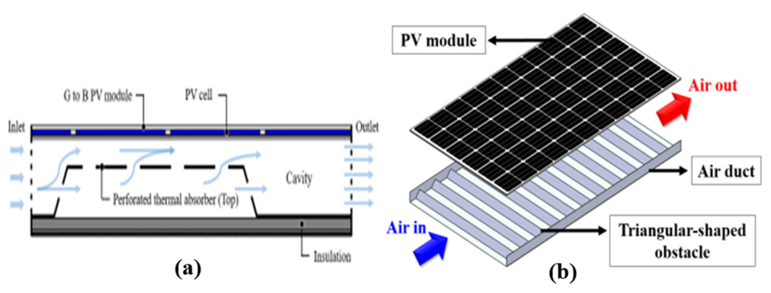
Several configurations using different shapes of obstacles in the airflow channels of PVT hybrid air collectors have been proposed in previous studies. Rectangular, triangular, inclined, perforated, curved, V-shaped and T-shaped baffles combined with fins are used as artificial roughness, generating turbulence in the air ducts for improved system cooling. The application of triangular baffles in an air-cooled PVT hybrid collector improves heat transfer in the air duct by cooling the PV solar cells [54]. The arrangement of the triangular baffles and the height of the air gap at the back of the PV module has an effect on the electrical performance of the PVT-air hybrid collector [55]. The electrical performance of the PVT hybrid collector improves when the horizontal spacing of the baffles is wider and the vertical spacing is narrower, while a high number of baffles decrease the electrical efficiency according to Yu et al. [55]. According to the same authors, the length of the baffles should be less than 150 mm and the slope of the baffles should be greater than 30° to obtain better air mixing in the duct. In addition, a collector slope of -30° moves the vortices towards the center of the channels, unlike a slope of +30°, which improves the heat transfer rate [55]. The use of perforated baffles in an air-cooled PVT hybrid collector shows that the total exergy efficiency of the air-cooled PVT hybrid collector with perforated baffles ranges from 24.8% to 30.5% when the total energy efficiency ranges from 44.1% to 63.3% [56]. With curved baffles, thermal and electrical efficiencies vary from 37.1% to 6.4%. The annual heat gain is 644 kWh and the annual electrical power generated is 118 kWh [57]. When triangular-shaped obstacles are used in the air duct of a PVT hybrid collector, the daily average thermal, electrical, overall and exergy efficiencies are 24.73%, 15.59%, 62.83% and 15.57%, respectively, while these efficiencies for an unobstructed air PVT hybrid collector are 17.08%, 15.30%, 54.47% and 15.13% respectively [58]. The annual energy and exergy yield of the PVT hybrid collector with triangular obstacles are 12.84% and 1.98%. These values are higher than those of the air-cooled PVT hybrid collectors without obstacles. Triangular and perforated obstacles can therefore effectively improve the electrical performance of the air-cooled PVT hybrid collector (see Figure 8).
With the application of the circular ribs (Figure 9.a) in the air duct of a PVT hybrid collector, the temperature of the PV solar cells dropped by 10°C compared to the PVT hybrid collector without ribs at an inlet air velocity between 1 and 3.5 m/s. The presence of the ribs induces large recirculation zones so that the air cooled near the bottom of the channel is partially re-injected upwards to extract heat from the PV cells. Similarly, the electrical efficiency of PV solar cells depends on their temperature and increases with increasing incoming air velocity. The rib configuration, where the ratio of the distance between the circular ribs to their diameter is 8, offers better performance [59]. According to Popovici et al. [31], the increase in maximum power produced by the PV module with ribs is 6.97% to 7.55% for rib angles of 90° to 45°, respectively compared to the PV module without ribs. Finally, according to Saadi et al. [60], increasing the number of triangular ribs (Figure 9.b) decreases the PV solar cell temperature and increases the PVT hybrid collector outlet air temperature. The inter-rib spacing provides the turbulent air flows that promote heat transfer by forced convection within the airflow channel and can be optimized for all values of inlet air velocity [60].
Integrating the fins into the air flow channel increases the heat transfer area between the air and the duct. A significant improvement in the cooling of PV solar cells and a high temperature at the outlet are obtained [61]. Numerical and experimental studies of the electrical performance of PVT hybrid air collectors have therefore been carried out in recent years. The use of a finned PVT hybrid collector has the potential to significantly increase electricity production and reduce the cost of electricity [62].
A numerical study of a PVT air collector with fins on the inner side of the absorber plate showed that the fin structure in contact with the rear side of the PV module improves the heat transfer between the PV cell layer and the heat transfer fluid [63]. A steady-state thermal analysis of the finned and finless air PVT hybrid collector using the matrix inversion method showed that the finned air PVT hybrid collector has higher electrical and thermal efficiency than the finless air PVT hybrid collector. Output temperature, thermal efficiency and electrical efficiency are 41.39°C, 43% and 14% respectively for the finned air PVT hybrid collector [64]. An energy and exergy analysis of a PVT air hybrid collector with and without fins using a theoretical approach for different solar radiation (from 600 W/m² to 800 W/m²) and mass flow rates (from 0.01 to 0.05 kg/s) showed that the fluid temperature and overall efficiency of the PVT air hybrid collector with fins are 39.93°C and 55% respectively. The increase in energy efficiency of the PVT hybrid finned air collector is 7% and the exergy efficiency is 1% [65].
An air-cooled PVT hybrid solar collector with a double-pass configuration and with vertical fins in the channel, perpendicular to the airflow direction was studied by Kumar and Rosen [66]. The addition of extended fins significantly reduced the temperature of the PV modules from 82°C to 66°C. With the addition of the rectangular fins, the maximum thermal efficiency and electrical efficiency obtained were 56.19% and 13.75% respectively for four fins at a mass flow rate of 0.14 kg/s and solar irradiance of 700 W/m². Operating costs are reduced because the aluminium fins and metal foil fins are small compared with the width/length and depth/length ratios of the PVT hybrid collector [67]. Tonui and Tripanagnostopoulos [14] presented the use of a thin flat metal sheet suspended in the middle of the air duct or fins on the back wall of an air duct to increase heat transfer in an air-source PVT hybrid solar collector. Under natural air flow, the temperature reached around 12°C in the early afternoon on sunny days and led to sufficient air flow for adequate air ventilation. For forced convection with a flow rate of 60 m3/h and a duct depth of 15 cm, the use of fins gave an overall efficiency of 30%, followed by thin sheet with 28%. The reference PVT hybrid collector with an overall efficiency of 25% for the models studied and the suggested modifications gave better electrical performance due to the cooling of the PV module. The parametric analysis shows that the mass flow rate, and therefore the thermal efficiency, decreases with increasing ambient temperature and increases with increasing tilt angle for a given level of insolation. It is also shown that there is an optimum airflow channel depth at which the mass flow rate is at its maximum and is between 0.05 and 0.1 m for the different configurations [14]. According to [68], optimum operating conditions are achieved for a PVT hybrid collector with a length of 1.5 m, a channel height of 1 cm and an air velocity of 2.3 m/s. For the optimal design, the overall efficiency and output temperature values are evaluated at 53.4% and 310.9 K respectively. Parametric analysis has shown that the addition of fins improves the overall efficiency of the PVT hybrid collector by up to 19%. However, the addition of fins does not significantly affect the outlet air temperature nor does it improve the overall efficiency of the PVT hybrid collector above a critical channel height. Tabet et al. [69] have shown that the electrical efficiency of the PVT hybrid air collector increases as the number of fins increases. Al-Damook et al. [70] showed in their study that the use of offset fins has a significant impact on the electrical and thermal efficiencies of the PVT hybrid collector. The maximum combined efficiency for the PVT hybrid collector with offset fins is 84.7%, whereas the PVT hybrid collector without fins is 51.2%. Gholampour and Ameri [71] have shown that the energy and exergy efficiency of the PVT hybrid collector increases with increasing fin number and height. The same authors suggested that optimal operation of the PVT hybrid collector requires a mass flow rate of 0.074501 kg/s and a number of fins of 7.915937. Finally, when the collector is operated at a high mass flow rate, the temperature of the PV solar cells is reduced and the electrical efficiency of the PV module is increased [62]. Figure 10 illustrates the different fin configurations in an air duct.
Jet impingement cooling (Figure 11) is used to improve the energy performance of solar energy technologies such as PV panels, PVT hybrid collectors and concentrating PV panels [72]. The high heat transfer coefficient is achieved between the absorber plate and the air using impact jets. Geometric characteristics such as jet diameter, jet spacing and jet height influence the electrical performance of the PV module. Non-concentrating and concentrating PVT hybrid collectors (CPVT) cooled by impact jets produce more thermal and electrical energy [73]. A predictive model of a PVT hybrid collector using impact jets has been developed and predicts a total daily energy of 10% and 11% of the experimental value for thermal and electrical energy, respectively [74].
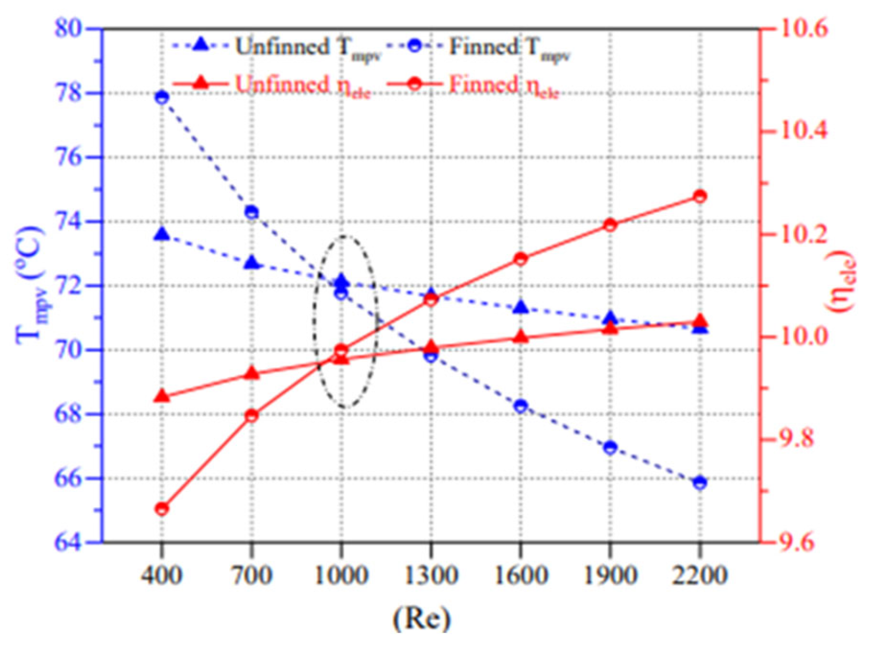
Figure 12 below shows the effect of PV module temperature on the electrical efficiency of the PVT hybrid collector with and without fins for a range of Reynolds numbers (400-2200). The temperature is inversely proportional to the Reynolds number; this is because the convective heat transfer coefficient is directly proportional to the Reynolds number.

4.5. Cooling of Photovoltaic Modules by Thermal Energy Storage

4.5.1. Cooling by Integration with Phase-Change Materials

The integration of phase change materials (PCM) in a PV module decreases its operating temperature and therefore increases its electrical efficiency of converting solar energy into electricity. The PCM is attached to the back of the PV module to control the temperature of the PV solar cells. PCM is very efficient and has a huge potential for thermal energy storage.
According to Kiwan et al. [75], when the PV module temperature exceeds the melting point temperature of PCM, the electrical efficiency of the PV module increases. However, when the temperature of the PV module is lower than the melting temperature of the PCM, the PCM will negatively affect the electrical efficiency of the PV module. Integrating the RT35HC PCM with a thickness of 4 cm reduces the PV module temperature by 8°C compared to the reference PV module [76]. Numerical and experimental analysis of the temperature control of a PV module by integration of a PCM under Malaysian weather conditions has shown that a 2 cm wide PCM layer of RT 35 used results in the reduction of the PV module temperature by 10°C which remains constant for a period of 4 to 6 hours [77].
The electrical performance analysis of the inclined PV/PCM module, taking into account heat transfer from the three heat transfer modes, was performed by Khanna et al. [27]. The results showed that when the tilt angle is increased from 0 to 90°, the temperature of the PV module with PCM decreases from 43.4°C to 34.5°C; resulting in an increase in the electrical efficiency of the PV module from 18.1% to 19% [27]. A comparative study of the PV, PV/PCM and PV/PCM modules with fins taking into account the different heat transfer modes showed that the most appropriate depth of the PCM is 2.8 cm for solar irradiation of 3 kWh/m²/day and 4.6 cm for solar irradiation of 5 kWh/m 2/day for a PV/PCM module [78]. To keep the PV module temperature low, the best spacing between successive fins is 25 cm, the best fin thickness is 2 mm and the best fin length is where it touches the bottom of the air duct. For the finless PV/PCM module, the most appropriate depth of the PCM container is 2.3 cm for a solar irradiance of 3 kWh/m²/day and 3.9 cm for a solar irradiance of 5 kWh/m²/day [78].
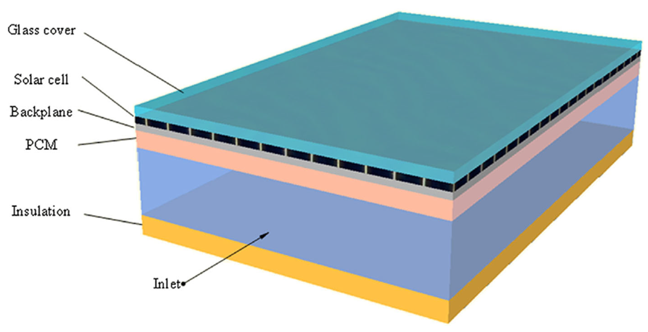
The addition of PCM in hybrid PVT collectors provides a double advantage in terms of cooling PV solar cells and heat storage. Numerical and experimental studies of the energy performance of PVT flat-air solar collectors with a PCM have been carried out in recent years. The position of the PCM layer in the hybrid air-based PVT collector has a significant effect on its energy performance (Figure 13). A comparative study of the integration of a PCM in an air duct of a hybrid PVT collector shows that its electrical efficiency is 10.7% higher than that of a hybrid PVT collector without PCM. In addition, for a hybrid PVT collector with PCM, it is verified that a 3 cm thick layer of PCM is excellent both in terms of electrical and thermal performance [79]. Systems such as PV/PCM, PV/PCM/thermoelectric and concentrated PV (CPV/PCM) have shown that cooling with PCM lowers the temperature of the PV module by an average of 6°C and increases the electrical efficiency by an average of 5.1% [80]. There is a 25% and 35% decrease in the temperature of the PV/PCM and PVT/PCM air modules respectively compared to the standard PV module. As a result of this temperature drop, the electrical efficiency of the PV module increases by 14.12% and 19.75% for the PV/PCM and PVT/PCM modules respectively [81]. The daily electrical efficiency of the air-powered hybrid PVT/PCM collector was 31.35% while that of the PV module is 13.12%, resulting in a 20.45% increase in the ability to extract useful energy from the sun by the hybrid PVT/PCM collector [82]. Four absorbers, placed in the PCM (pig fat-like PCM) layer of an air-powered hybrid PVT collector, required a PCM that balanced energy production [83]. An experimental study of a hybrid PVT/PCM air collector composed of a flexible copper-indium-gallium-selenide (CIGS) PV module, flat plate solar collector and solid PCM shows that the temperature of the absorber plate and PV module was reduced by 15 °C and 20 °C for the hybrid PVT air collector without PCM. The PV module output of the hybrid PVT/PCM collector is 6.7 % higher than the air-powered PVT hybrid collector without PCM [84]. An experimental evaluation showed that a nano-cooled hybrid PVT collector gives thermal and electrical efficiencies of 72% and 13.7%, respectively [85]. Ahmed and Nabil [61] studied the influence of temperature on the electrical behaviour of the PV module with and without forced convection cooling in three configurations, namely: hybrid PVT collector with an air channel under the plate, PVT hybrid collector with a fin channel and PVT hybrid collector with an embedded PCM between the fins. The results show that increasing the thickness of the PCM improves the cooling of the PV module [61].

4.5.2. Cooling of Photovoltaic Modules by Heat Pipe

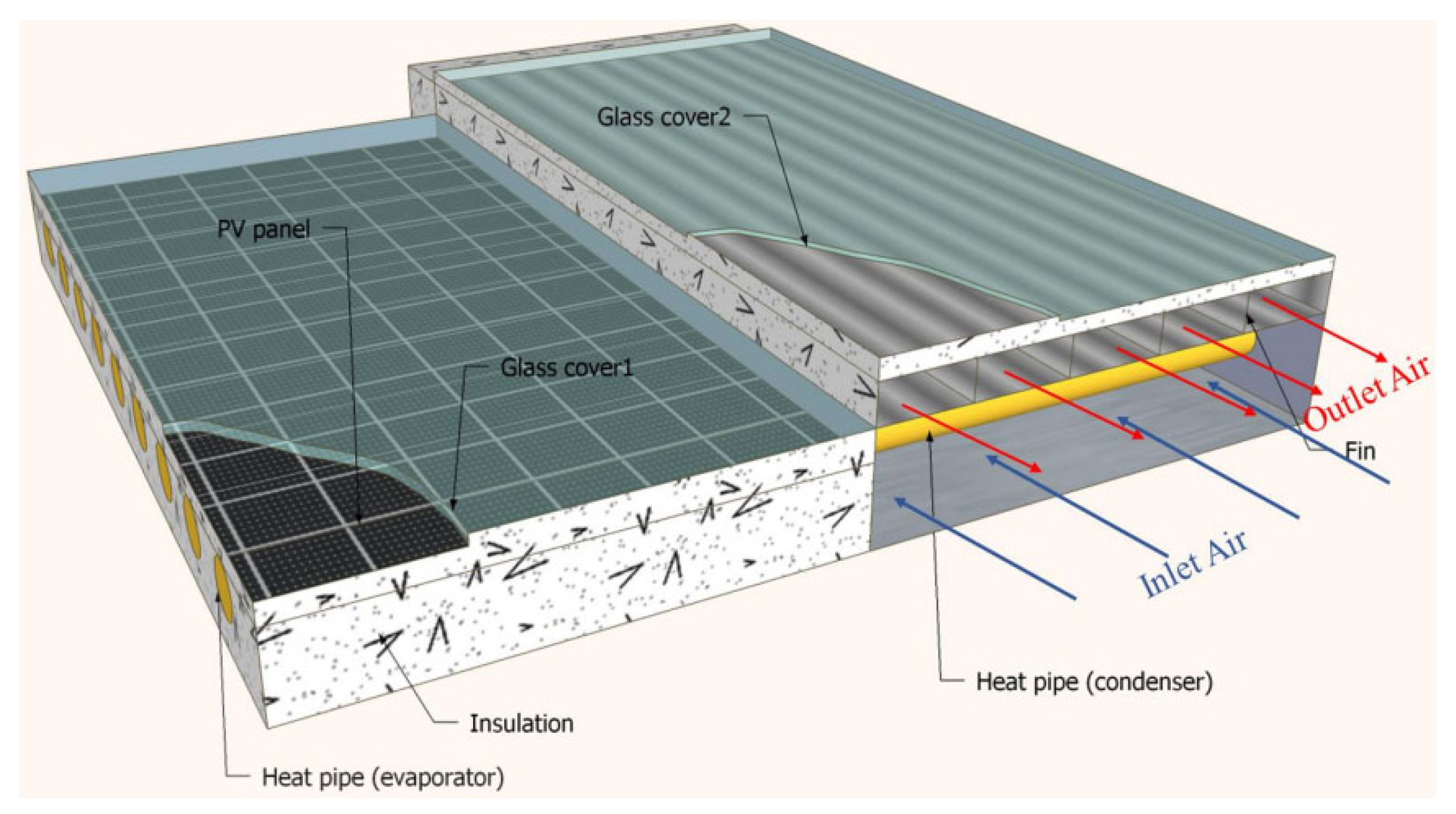
Heat pipes are an efficient heat transfer technology that uses the phase changes (evaporation and condensation) of the heat transfer fluid to transport a large amount of heat over a long distance. Research has been carried out on the potential use of heat pipes to improve the electrical performance of PV modules. Numerical and experimental studies of the thermal and electrical performance of hybrid vacuum tube PVT collectors have been the subject of research in recent years. Nougblega et al. [83] showed that the hybrid vacuum tube PVT collector is thermally more efficient than a hybrid PVT with confined air blade and that an optimal flow rate maintained by a fan showed that the hybrid vacuum tube PVT collector is electrically efficient. Fan et al. [87] have developed a dual-pass PVT air heating system (PVT-SAH) integrated with heat pipes for applications requiring high temperature air. The PVT-SAH hybrid collector with heat pipes provides an efficient cooling effect to the PV module and improves the temperature uniformity of the PV module. The temperature variation over the length of the PV module for the proposed system and for the reference design is 9.4°C and 21°C respectively [87]. In addition, the maximum thermal efficiency of the PVT-SAH heat pipe collector is 69.2% compared to 61.7% for the reference design. Zhou et al. [88] have shown that the factors influencing the energy performance of the PVT heat pipe hybrid collector are mainly solar radiation, mass flow rate and wind speed [88]. A numerical and experimental study shows that the thermal and electrical efficiencies of the heat pipe hybrid PVT collector are 41.9% and 9.4% respectively [89]. The PVT heat pipe hybrid collector is shown in Figure 14.

4.5.3. Cooling of Photovoltaic Modules by Integrating Porous Media

Porous media play an important role in the energy storage process. They have a very large influence on the electrical performance of a PV module. Research has been carried out in recent years on the use of porous media.
Cooling of a PV solar module with a porous PCM with different inclined angles was studied numerically and experimentally by Duan [90]. From the study of Duan [90], the angle of inclination causes a low natural convection for the liquid PCM in the metal foam and the low convection plays a negative role in the process of melting the PCM. The melting time of PCM in 90° metal foam is 1.9 times greater than that with an angle of 0° when porosity is 95%. Under the heat flow limit, Porous PCM with a greater porosity of 95% plays a poor role in cooling the PV module. In addition, the temperature of the PV module increases when a porous PCM is used with a greater porosity of 95% and the cooling time is twice as short as when a PCM with a smaller porosity (85% or 90%) is used. However, when the Rayleigh number is reduced from 1.4568.106 to 1.1654.1010, the time that maintains the temperature of the silicon PV module from 40°C to 60°C decreases by 1.3 times [90].
The use of porous media increases the heat transfer area, thus increasing the electrical and thermal efficiency as well as the temperature of the PVT hybrid collector outlet air. Ahmed and Mohammed [91] built a dual-pass air-based hybrid PVT collector to study the influence of porous media on system performance. The results showed that the overall efficiency increased by 3% after using the porous medium in the lower ducts of the hybrid PVT double-pass collector. The reduction of the temperature of the PV module with the increase in air speed led to the increase in the electric efficiency of the hybrid PVT collector. The authors finally concluded that the use of a porous medium and glass cover in the PVT hybrid collector is a desirable option for power generation. According to Hussain et al. [92], a hexagonal honeycomb heat exchanger installed horizontally in the air flow channel under the PV module of a single-pass hybrid PVT collector effectively improves its electrical performance. At a mass flow rate of 0.11 kg/s, the thermal efficiency of the honeycomb-free system is 27% and with honeycomb 87%. The electrical efficiency of the PV module therefore improved by 0.1% over the whole mass flow range from 0.02 kg/s to 0.13 kg/s at an irradiance of 828 W/m² [92]. The hexagonal honeycomb configuration is more efficient as a heat exchanger with an electrical efficiency of 7.13% and thermal efficiency of 87% for a mass flow rate of 0.11 kg/s [93]. This improvement in the energy performance of the PVT hybrid collector by the honeycomb is due to its large surface touching the back of the PV module and its ability to create air flows; which improves heat transfer from the back of the PV module to the circulating air [93]. Hybrid PVT collectors using a porous medium are shown in Figure 15.

4.6. Cooling of Photovoltaic Modules by Coupling Fins or/and Baffles with Phase-Changing Material

The coupling of the fins or obstacles with the PCM regulates the temperature of the PV modules by improving their electrical performance. The use of PCM coupled to fins has led to a good distribution of module temperature compared to the use of single PCM, significantly improved cooling of the PV module and leads to high outlet air temperatures [61,94].
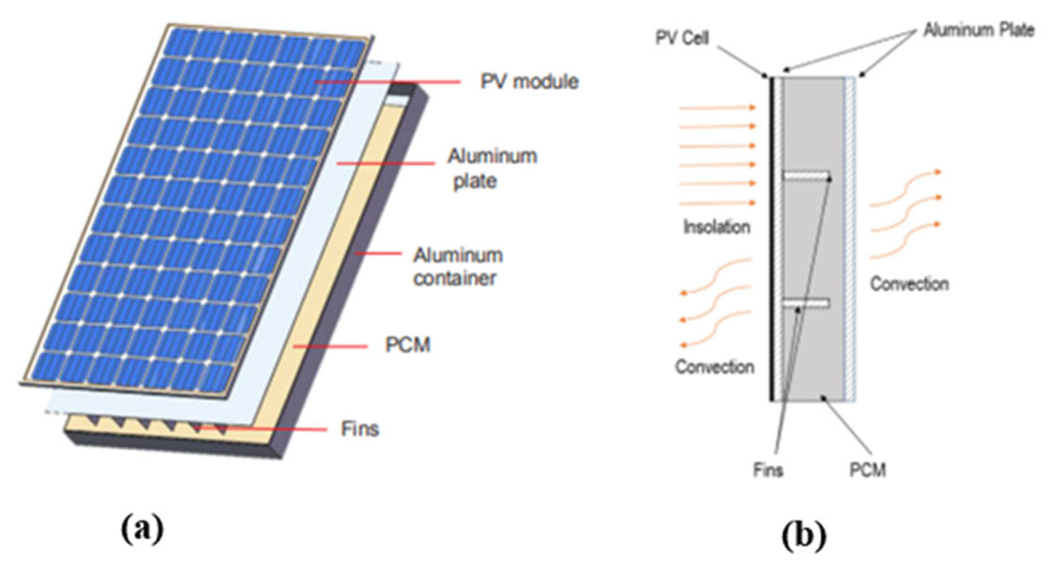
Coupling the fins to the PCM accelerates the fusion of the PCM by 3.5 min at a depth of 2 cm and 14 min at a depth of 3 cm compared with using the PCM alone [94]. The temperature of the PV module decreased by 18.3% when using only PCM and 27.8% when the PCM is coupled to the fins compared to the PV module without PCM. In addition, to control the temperature of the PV/PCM module with fins, the best distance between successive fins is 25 cm, the best fin thickness is 2 mm and the best fin length is where it touches the bottom of the air duct [78]. Ma et al. [95] have shown that an increase of 100 W/m² in solar radiation can cause a temperature increase of about 5°C in the PV module and that optimal performance can be achieved when the melting temperature of the PCM is slightly higher than 5°C, at room temperature. The PV module using a PCM coupled to the fins is shown in Figure 16.
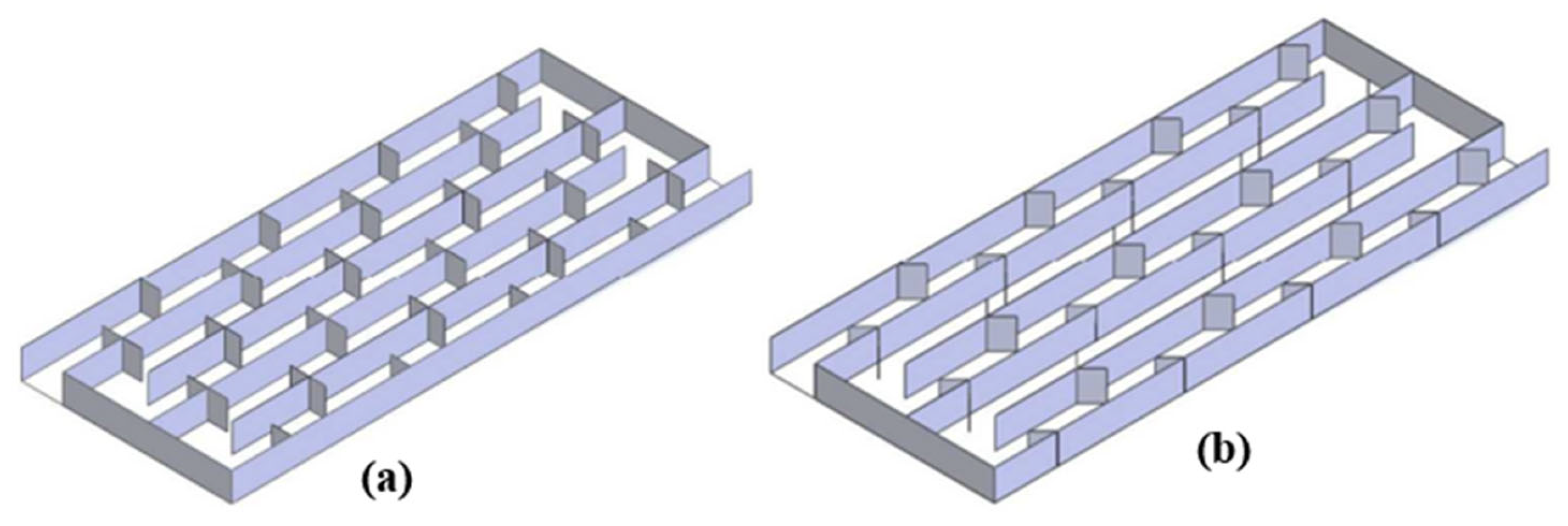
An experimental analysis of the energy and exergetic efficiencies of five different absorber configurations in the air flow channel of a PVT hybrid collector is conducted by Srimanickam and Sarayan [53]. The absorber configurations were; reference air channel, single fin channel, multiple fin channel, T-baffle-coupled fins and V-baffle-coupled fins (Figure 17). The results showed that the coupling of the fins to the V-shaped baffles has higher electrical and thermal performances compared to other configurations due to its physical geometry being rich in artificial roughness. The coupling of fins and baffles ensures a good turbulent air flow in the duct, which increases the electrical performance of the PVT hybrid collector [53].

4.7. Cooling by Improving Absorption of Solar Radiation

4.7.1. Radiative and Photonic Cooling

Radiative passive cooling is a method of dissipating excess heat from a material by the spontaneous emission of infrared thermal radiation. This cooling technique improves the electrical efficiency of PV solar cells under outdoor conditions as well as their service life. This approach also involves optimizing the solar radiation received from PV solar cells (with the help of photonic structures) by taking advantage of the transparency window offered by the atmosphere in the 8-13μm wavelength range [96,97]. An experimental study by Zhao et al. [96] showed that the electrical performance of radiative cooling systems in the sky is largely dependent on local weather conditions, such as atmospheric constituents (water vapour), clear or cloudy sky conditions, local wind speeds and variability of weather [96]. Jérémy Dumoulin et al. [98] studied the effect of radiative cooling from the sky on single junction PV solar cells on three semiconductor materials: silicon, gallium arsenide and perovskite. The developed numerical model based on thermal balance, allows to estimate the temperature and electrical power for different technologies of PV solar cells. A broadband emissivity profile provides the best electrical performance for radiative sky cooling of single junction PV solar cells under terrestrial conditions. The numerical simulations also show that radiative cooling of the sky reduces the temperature of PV solar cells by 10°C, thus increasing their output power by more than 5 W per m². For silicon PV solar cells, a 20% reduction in parasitic absorption produces the same effect as a 10% increase in emissivity above 4mm. For gallium arsenide and perovskite PV solar cells, the effect is even more pronounced. However, radiative cooling of the sky is only feasible under controlled atmospheric conditions. Radiative night cooling has therefore been a success in recent years [98]. Bin Zhao et al. [99] designed a radiatively cooled PV module to generate electricity during the day by photovoltaic conversion and simultaneously obtain radiative cooling energy at night (Figure 18). On a sunny day, the electrical performance of the PV module showed that the average daily electricity generation and electrical efficiency are respectively 94.0 W/m² and 14.9%. The net cooling power was estimated at 72.94 W/m² when the temperature of the PV module is equal to the ambient air temperature [99].
The use of photonic cooling methods, especially Doppler cooling on PV solar cells improves the thermodynamic property of semi-materials conductors where the increase in temperature leads to a decrease in the electrical efficiency of PV modules [100]. Gordon et al. [101] have shown that the ability of photonic cooling semiconductor materials in range of 100 K to 300 K theoretically improves the electrical efficiency of PV modules by more than double current practical results. However, when cooling semiconductor materials operate at low temperatures (below 100 K), PV solar cells act as insulators. Thus, PV modules can be optimized with photonic cooling systems [101]. The photonic cooling of PV solar cells in monocrystalline silicon gives a daytime electrical power of 99.2 W/m² and produces a night electric power of 128.5 W/m², respectively with an electrical efficiency of 6.9% and 30.5% higher than those of PV solar cells without photonic cooling [102]. The concept of photonic cooling for a PV solar module is shown in Figure 19.

4.7.2. Thermoelectric Cooling of Photovoltaic Modules

The thermoelectric cooling technique is used to integrate a Peltier module under the PV solar cells. This technique improves the electrical efficiency and longer life of PV solar cells by effectively capturing solar radiation through a division of the solar spectrum (see Figure 20). This device is a photovoltaic-thermoelectric hybrid module (PV/TE) which simultaneously engages the photovoltaic and the Peltier effect (thermoelectric). The Peltier module allows for cooling of PV solar cells and keeps them operating at an ambient temperature that enables them to generate their maximum power [103].
An experimental study by Senthil Kumar et al. [104] showed that the electrical efficiency, front and back PV module temperature and thermoelectric PV module outlet air temperature are respectively 11.87%, 54.5°C, 43.1°C and 46.0°C. A comparative study of the use of thermoelectric cooling and natural cooling of the PV module at free convection shows an increase in the electrical efficiency and power of the PV module of 10.50% and 10.50%, respectively [105]. According to Babu and Ponnambalam [106], a thermoelectric PV module of different configurations generates 10-20% energy with an overall efficiency of 40-50%.
Improved energy performance can also be achieved by using hybrid PVT solar collector technology in combination with thermoelectric generators. The PVT/TE hybrid collector has a higher electrical efficiency than the PVT hybrid collector but the PVT hybrid collector has a higher thermal efficiency than the PVT/TE hybrid collector [107]. Numerical analysis showed that the electrical efficiency of the PVT hybrid collector and the PVT/TE hybrid collector is 6.23% and 10.41% respectively. By increasing the ambient temperature from 26°C to 34°C, the electrical efficiency of the PVT hybrid collector decreases by 1.43% and the PVT/TE hybrid collector increases by 0.82% [107]. For a semi-transparent PVT hybrid collector combined with a thermoelectric cooler, the electrical efficiency is higher than that of the semi-transparent PV module by 7.266% and higher than that of the semi-transparent PV-TE solar module by 4.723% [108]. In a steady state, a hybrid PVT-TE air collector provided maximum thermal and electrical efficiencies of 84% and 12%, respectively [109]. Finally, the electrical efficiency of the PVT/TE hybrid collector increases when V-grooves, aluminum fins and thin metal sheets are used in the air duct [38].

4.7.3. Cooling by Integrating Photovoltaic Modules in Buildings

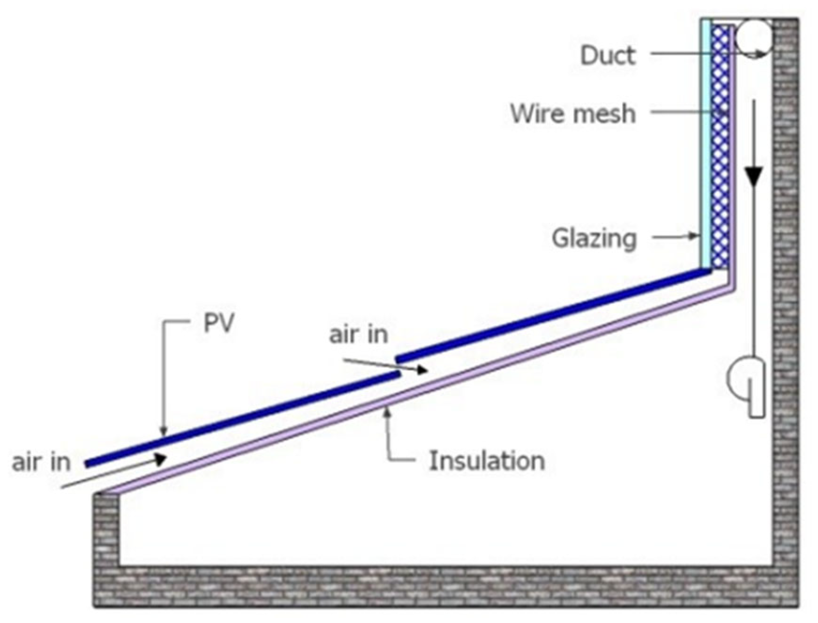
Building-integrated PV modules (BIPV) are power generation systems that are integrated into a roof, facade or windows of buildings. The integration of PV modules into buildings is a cooling technique for PV solar cells that maximizes the capture of solar radiation in useful energy. The improvement of electrical performance of PV panels integrated into buildings by passive cooling has been investigated experimentally and numerically by Hamed et al. [110]. They showed that the BIPV with a narrow channel reduces the operating temperature of the PV panel. This improved PV panel heat transfer reduces the temperature of the PV panel by 5 to 10°C. The results also show that having a 30 cm channel under the PV module can increase power generation by 3% to 4%. Inclusion of one channel thus results in passive cooling by radiative and convective heat exchange [110]. When the mass flow rate is 0.04 kg/s during PV module cooling, energy and exergy efficiencies reach 11.9% and 12.4%, respectively [111]. Cooling can therefore increase electricity production by 7-15%. The BIPV module has a significant influence on heat transfer through the building envelope due to the modification of the thermal resistance by adding or replacing building elements [111]. Wang et al. [112] designed four PV modules integrated into different buildings: the BIPV with ventilated air blade, the BIPV with non-ventilated air blade, the BIPV roof mounted module and the conventional roof without the PV module and without air blade. The simulation results show that the BIPV ventilated air blade module is suitable for summer application as this integration leads to low cooling load and high electrical efficiency. In winter, the BIPV module with a non-ventilated air blade is more appropriate due to the combination of low thermal load through the roof and high electrical efficiency of the PV module [112].
When air-powered PVT hybrid collectors are integrated into buildings, they provide more useful energy per unit area than solar PV modules alone. Several analytical, numerical and experimental studies of the performance of hybrid PVT air collectors integrated into buildings have been carried out in recent years. Kim et al. [113] experimentally conducted a comparative study between a hybrid PVT air-integrated solar collector (BIPVT) and a building-integrated PV module (BIPV). The results show that the BIPVT hybrid collector can maintain a lower temperature of the PV solar module than the BIPV with a temperature difference of about 22°C. The BIPVT hybrid collector can also maintain an electrical efficiency of 14% even when the solar radiation is high compared to 12% of the BIPV module. Another comparative study of semi-transparent PVT hybrid collectors integrated in the building and opaque hybrid PVT collectors integrated in the roof of a room with and without air duct was carried out by Vats and Tiwari [114]. Results show that a maximum ambient air temperature of 18°C and a minimum ambient air temperature of 2.3°C were observed for the semi-transparent PVT collector without an air duct and the opaque PVT hybrid collector [114]. Yang [115] has carried out another comparative study which shows that the use of semi-transparent PV modules in hybrid PVT collectors increases thermal efficiency by up to 7.6% compared to opaque hybrid PVT collectors, especially when combined with multiple entries. A semi-transparent hybrid PVT collector integrated on the roof (called room 1) to study the performance of a room (called room 2) shows that the optimal thickness of the roof for minimum temperature fluctuations inside the room is between 0.30 m and 0.40 m. Due to direct heating, room 1 has very high temperatures (above 40°C) and can therefore be used as a greenhouse for drying high value crops [116]. A numerical analysis of the transient mixed convective air flow in a solar building stack was performed on a hybrid PVT solar collector using a flow function and vorticity formulation [117]. The PVT hybrid building collector model offers good electrical performance while the PVT reverse solar chimney collector provides good thermal efficiency. Another study on a hybrid PVT solar chimney integrated into the building for natural cooling of premises is digitally analyzed by using mixed convection [118]. The results of the analysis show that the increase in Reynolds number leads to a higher airflow for passive cooling and better electrical efficiency of PV solar cells. The performance evaluation of a hybrid PVT double-pass solar collector shows that the temperature of the outlet air is 63°C at a mass flow rate of 0.017 kg/s and the electrical, thermal and overall efficiency is 12.65%, 56.73% and 85% respectively at a flow rate of 0.031 kg/s. In addition, the optimum electrical power and thermal energy reached 50.57 W and 389.37 W at 0.031 kg/s [119]. Figure 21 shows a cross-sectional view of the PVT solar collector integrated into the building.

4.7.4. Cooling by Using Bifacial Photovoltaic Modules

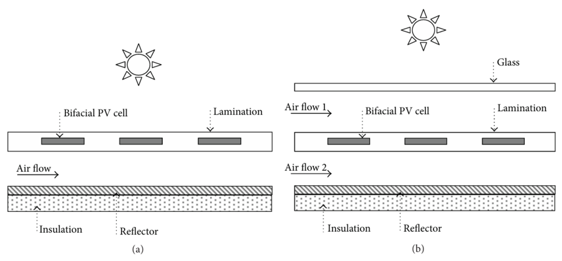
Bifacial PV modules have two identical active surfaces front and back that can capture solar radiation with its front and rear surfaces. Simultaneous absorption of sunlight through both surfaces results in improved power generation compared to conventional single-axis PV modules [120]. The bifacial hybrid PVT collector is now considered attractive because of its potential to improve overall collector performance from the same surface of the PV module. A hybrid PVT collector with a bifacial PV module can produce about 40% more electrical energy than a single-face hybrid PVT collector [120].
A study of bifacial dual-pass and single-single hybrid PVT collectors showed that overall efficiencies of 45% to 63% are observed for the parallel dual-pass bifacial hybrid PVT collector. Therefore, the parallel dual-pass bifacial hybrid PVT collector is preferred because it generates up to 20% more total energy than the single-channel collector despite its low daily exergy efficiency [121]. An experimental analysis of four bifacial PV modules with four different fill factors of hybrid air PVT collectors showed that the dual-pass parallel flow design gave the highest energy efficiency from 51% to 67%, and the single-pass design reported the lowest total energy efficiency of 28% to 49% with a fill factor of 0.7. The single-pass bifacial PVT hybrid collector design is the best option if electrical energy is the desired output energy. However, the dual-pass parallel flow design is the best option if thermal energy is the desired output energy [121]. Figure 22 shows the cross-sectional view of a bifacial hybrid PVT solar collector.

4.8. Cooling by Different Configurations of the Conduits and Absorbers

The use of extended surfaces in the airflow channels of PVT hybrid air collectors is a cooling technique that increases the heat transfer area between the absorber surface and the air flowing through the duct. In the literature, extended heat transfer areas include the dimensions of the absorber and flow channels, the insertion of double or multiple air channels, the integration of porous media with the air channels and the development of absorber plates. Design parameters such as absorber thickness and fluid flow channel diameter influence the energy performance of PVT hybrid collectors. Farshchimonfared et al. [122] showed that the optimal depth of the air flow channel increases as the length-width ratio (L/W) and the surface area of the hybrid PVT air collector increase. In addition, the optimum depth for a hybrid PVT collector with specified areas and values of the L/W ratio considered varies between 0.09 and 0.026 m.
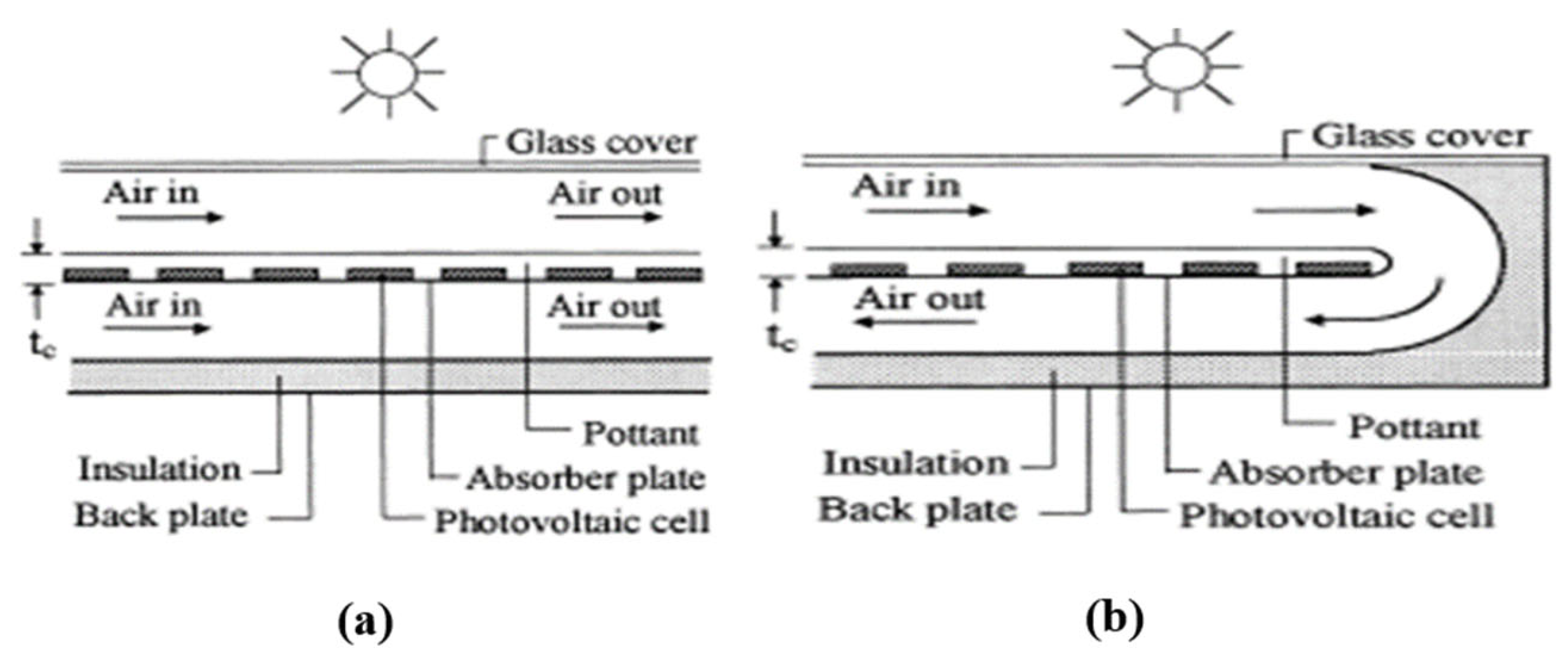
The direction of air flow has an effect on the electrical and thermal efficiency of single-pass and double-pass hybrid PVT air collectors with rectangular fin absorbers. The use of a dual-pass hybrid PVT air collector increases its performance compared to single-pass hybrid PVT (see Figure 23). With an air mass flow rate of 0.048 kg/s, the thermal efficiency reaches 73.23% and the electrical efficiency 10.16% [123]. A comparative study of a solar PV module, a standard hybrid PVT air solar collector, an air-based PVT glazed hybrid collector and a double-pass air glazed hybrid PVT collector showed that the overall efficiency of the double-pass air glazed hybrid PVT collector is 74% higher than other solar systems with an air flow rate of 0.023 kg/s. By integrating an indirect solar dryer system into the PVT hybrid collector, the electrical, thermal and overall efficiencies were 10.5%, 70% and 90% respectively for a flow rate of 0.0155 kg/s [124].
Absorbers of different shapes increase the airflow path in a PVT hybrid collector; this improves its energy performance. An examination by Wu et al. [125] shows that there are seven different types of thermal absorbers and four corresponding integration methods for various PVT hybrid collectors. Absorbers such as heating micro-channel heat pipe network, extruded heat exchanger, roll-bond heat exchanger and cotton wick structure are promising compared with traditional thermal absorbers, such as sheet and tube structure, the rectangular tunnel with or without fins/grooves and flat tube due to significant improvement in efficiency, structure, weight and cost, etc. The vinyl acetate-based integration method is the best option for integrating PV module with thermal absorber compared to other conventional methods such as direct contact, thermal adhesive and mechanical fixation. According to Jin et al. [126], the single-pass hybrid PVT collector with a rectangular tunnel absorber provides better electrical and thermal efficiency than the hybrid PVT collector without a rectangular tunnel absorber. The electrical, thermal and combined efficiencies obtained are respectively 10.02%, 54.70% and 64.72% for a solar irradiance of 817.4 W/m², a mass flow rate of 0.0287 kg/s and an ambient temperature of 25 °C [126].
Othman et al. [93] have shown experimentally that at a mass flow rate of 0.11 kg/s, the thermal efficiency of the single-pass PVT hybrid collector with v-groove is 71% and that of stainless-steel wool is 86%. The electrical efficiency of the systems is 7.04% and 6.88%, respectively. With a v-groove absorber, the output temperature, thermal efficiency and electrical efficiency are 75.96°C, 80.10% and 24% respectively [127]. A theoretical and experimental study of a V-groove absorber shows that the electrical, thermal and overall efficiencies are in the range 10.39% to 10.26%, 41.78% to 41.57% and 52.17% to 51.81% respectively [128]. An energy analysis of a V-groove hybrid PVT collector at steady state shows that the average energy efficiency is 65.52% and 66.73% for theoretical and experimental studies, respectively [65]. Yu et al. [129] analyzed the heat transfer in parallel cooling channels with periodically expanded grooves. The presence of periodically expanded grooves causes vortex in the grooves and pressure losses in parallel cooling channels. The average temperature of the PV module with periodically expanded grooves is about 4 K lower than that of a smooth channel. A theoretical and experimental study of a V-wave absorber in an air-powered hybrid PVT collector provides exergetic efficiencies of 13.36% and 12.89%, respectively [130]. An iterative simulation applied to different absorbers, namely the V-grooves and curved grooves, indicates a decrease in the temperature of the PV module and the air outlet temperature. The energy efficiency of the PVT hybrid collector with curved grooves in the absorber is improved when the absorber form factor is between 1.3 and 2 [131]. Figure 24 shows the cross-sectional view of a PVT hybrid collector with a V-groove heat exchanger.
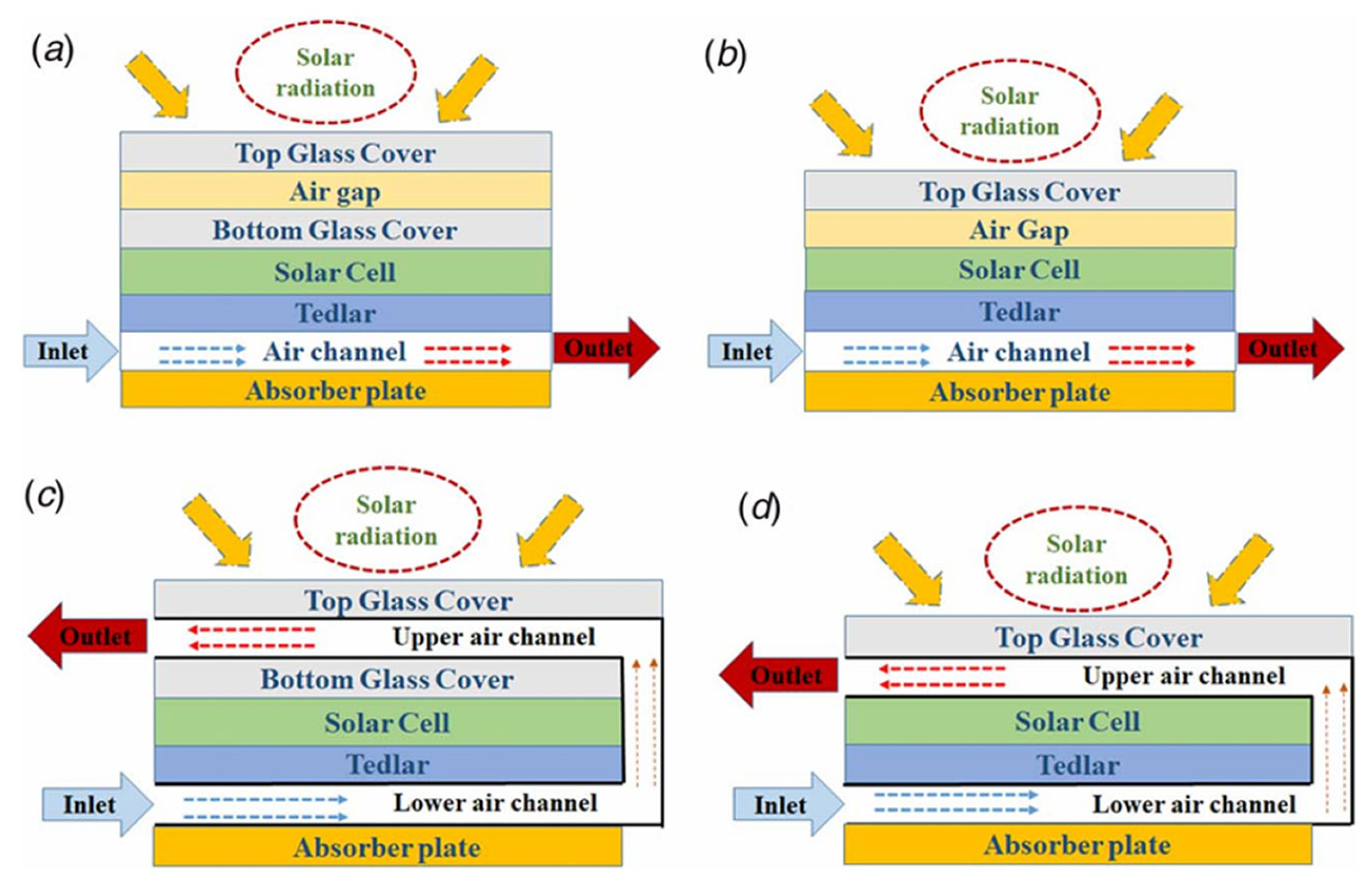
Modification of the structure of the standard PVT flat-air hybrid collector by removing the top glass layer or adding a gap with an upper glass layer or creating a double pass channel (see Figure 25) for cooling PV solar cells, effectively improves the overall performance of the PVT hybrid collector. According to El-Hamid et al. [132], the average daily overall energy and exergetic efficiencies are 85.06% and 13.92% for the single-glazed and double-pass hybrid PVT collector respectively and 82.12% and 12.95% for the double-glazed PVT hybrid collector [132]. In addition, the single-pass double glazing configuration with air blade has the lowest thermal and electrical efficiencies. Omer and Zala [43] have experimentally shown that the overall daily efficiency of a glass-coated hybrid PVT collector is 90.48% while that of the non-glass-coated PVT collector is 62.16%.
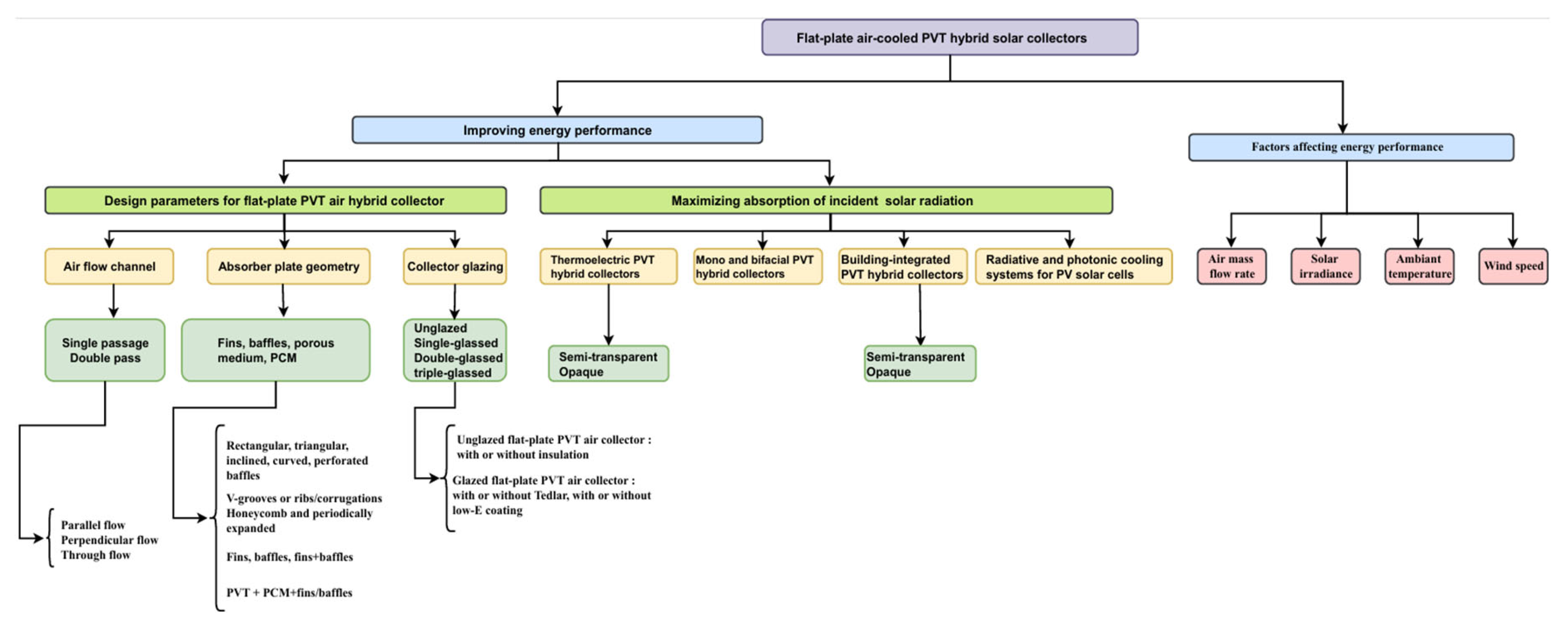
An experimental study of two air duct configurations, one double-pass and the other single-pass, using a hybrid PVT air collector shows that the average electrical efficiency increases from 14.23% to 14.81% with an increase in the mass flow of air. In addition, the average overall efficiency increased from 49.44% to 71.54% [133]. To determine the optimal configuration, Dadioti [134] studied the parameters that influence the optimal performance of hybrid PVT solar collectors. The simulation results show that single-cover, glazed PVT hybrid air solar collectors have proven to be the optimal configuration for residential applications where power generation is a priority [134]. Figure 26 illustrates the different techniques for improving energy performance of hybrid PVT air solar collectors and the factors that affect them.

5. Conclusions

This study examined cooling techniques that use air circulation to control the temperature of PV modules and therefore improve their electrical performance. The following main conclusions are drawn:
  • The cooling of PV modules by fin heatsinks provides an improved heat transfer zone to promote a greater heat transfer from the rear surface of the PV module to the ambient air through natural convection.
  • Cooling technique using artificial roughness (baffles, circular or triangular ribs) is a very effective method that significantly reduces the temperature of PV modules, which increases the coefficient of heat transfer between circulating air and absorber.
  • Cooling techniques using rectangular tunnel absorbers, hexagonal honeycomb absorbers, extruded absorbers behind the PV module and jets impacting in the air flow channel ensure good cooling of the PV modules. Hexagonal honeycomb and V-groove heat absorbers have shown the highest electrical performance of PV modules.
  • Cooling of PV modules by storing thermal energy using phase-change materials, heat pipes and porous media. These cooling techniques result in a significant change in the temperature of PV modules. Latent heat transfer through the PCM occurs during material melting, resulting in a high heat transfer rate. The electrical power and electrical efficiency of PV modules depend mainly on the thickness of the PCM. However, the application of PCM is limited by its high cost and low thermal conductivity. Heat pipe cooling reduces the operating temperature of PV modules. Porous media also play an important role in heat storage. They have a very large influence on the electrical performance of a PV module.
  • Thermoelectric cooling improves the electrical performance of PV modules by increasing the amount of solar radiation. The PV modules integrated into the building maintain electrical efficiency even if solar radiation increases. Bifacial PV solar modules also have potential for improved power generation compared to conventional PV solar modules. The design of the single-pass bifacial PVT hybrid collector is better when electrical energy is desired and if thermal energy is desired, dual-path parallel flow design is the best option. Photonic cooling of PV solar cells improves the thermodynamic property of semiconductor materials where the increase in temperature leads to a decrease in the electrical efficiency of PV modules. Radiative cooling with the sky is a passive cooling method that optimizes the conversion of solar radiation from PV solar cells in outdoor conditions, thus improving their efficiency of electrical power conversion.
  • The forced air-cooled PV module offers better cooling and energy conversion efficiency compared to natural air circulation. The electrical power and electrical efficiency of PV modules obtained from different active cooling techniques is mainly affected by the geometry of single-channel or double-channel cooling channels, glazing, insulation, the extended surfaces, the angle of inclination and their mass flow rates.
  • Several calculation methods and software have been used for the modelling and simulation of the heat transfer process and the cooling process of PV modules. A numerical simulation of mono, di and three-dimensional mathematical models, whether they are in steady-state or in dynamic mode, allow the determination of the temperature distribution of the PV module by numerically solving the governing energy equations with the finite difference method, the finished volumes or finished elements when the coolant flows. 1-D models provide more accurate results than 2-D and 3-D models because factors such as mesh quality, assumptions, and boundary conditions affect accuracy. However, they do not take into account the flow of fluid in all directions. In the 2-D and 3-D models, conduction and convection heat transfer are taken into account.
  • Despite the low thermophysical properties of air, hybrid PVT air solar collectors are preferred in practice because their design does not require enough materials and their operating cost is low.

Author Contributions

K.Ya. conducted the literature review and prepared the research paper, A.K.D.D., A.K.G., K.Ye., O.B. participated in reviewing the paper, and N.K. provided supervision. All authors have read and accepted the published version of the manuscript.

Funding

The work was supported by funding from the World Bank for the project “Centre d’Excellence Régional pour la Maîtrise de l’Electricité (CERME)” of Universty of Lomé (Crédit IDA 6512-TG; Don IDA 536IDA).

Data Availability Statement

Not applicable.

Acknowledgments

The authors are grateful to the World Bank for funding this research through CERME (Centre d’Excellence Régional pour la Maîtrise de l’Electricité).

Conflicts of Interest

The authors declare no conflicts of interest.

References

  1. International Energy Agency, IEA, « The global power mix will be transformed by 2028 », IEA.25 September 2024. https://www.iea.org/energy-system/renewables.
  2. Ritchie, H.; Rosado, P.; Roser, M. Fossil fuels. Our World in Data, janv. 2024, https://ourworldindata.org/fossil-fuels.
  3. Agrawal, B.; Tiwari, G.N. Building integrated photovoltaic thermal systems: for sustainable developments. in Energy series, no. 4. Cambridge, UK: RSC Pub, 2011.
  4. Bhatia, S. C. Advanced renewable energy systems. Woodhead Publishing India Pvt. Ltd., vol. Part I. in Woodhead Publishing India in Energy, vol. Part I. New Delhi: Vardaan House, 2014. www.woodheadpublishing.com.
  5. Kant, K.; Shukla, A.; Sharma, A.; Biwole, P.H. Thermal response of poly-crystalline silicon photovoltaic panels: Numerical simulation and experimental study. Sol. Energy 2016, 134, 147–155. [Google Scholar] [CrossRef]
  6. Kaplanis, S.; Kaplani, E. A New Dynamic Model to Predict Transient and Steady State PV Temperatures Taking into Account the Environmental Conditions. Energies 2018, 12, 2. [Google Scholar] [CrossRef]
  7. Sarbu, I. ; C. Sebarchievici, C. Solar Collectors. In Solar Heating and Cooling Systems, Elsevier, 2017, p. 29-97. [CrossRef]
  8. Abdin, Z.U.; Rachid, A. A Survey on Applications of Hybrid PV/T Panels. Energies 2021, 14, 1205. [Google Scholar] [CrossRef]
  9. Guarracino, I. Hybrid photovoltaic and solar thermal (PVT) systems for solar combined heat and power. Doctor of Philosophy, Imperial College London, Department of Chemical Engineering, 2017.
  10. Rahman, M.; Hasanuzzaman, M.; Rahim, N. Effects of various parameters on PV-module power and efficiency. Energy Convers. Manag. 2015, 103, 348–358. [Google Scholar] [CrossRef]
  11. Razak, A.; Irwan, Y.; Leow, W.; Irwanto, M.; Safwati, I.; Zhafarina, M. Investigation of the Effect Temperature on Photovoltaic (PV) Panel Output Performance. Int. J. Adv. Sci. Eng. Inf. Technol. 2016, 6, 682. [Google Scholar] [CrossRef]
  12. Dang, D.N.; Le Viet, T.; Takano, H.; Duc, T.N. Estimating parameters of photovoltaic modules based on current–voltage characteristics at operating conditions. Energy Rep. 2022, 9, 18–26. [Google Scholar] [CrossRef]
  13. Rouholamini, A.; Pourgharibshahi, H.; Fadaeinedjad, R.; Abdolzadeh, M. Temperature of a photovoltaic module under the influence of different environmental conditions – experimental investigation. Int. J. Ambient. Energy 2014, 37, 266–272. [Google Scholar] [CrossRef]
  14. Tonui, J.; Tripanagnostopoulos, Y. Improved PV/T solar collectors with heat extraction by forced or natural air circulation. Renew. Energy 2007, 32, 623–637. [Google Scholar] [CrossRef]
  15. Koita, D.; Popa, C.-V.; Robert, B.; Galatanu, C.-D. Numerical study of the effect of wind on the cooling of photovoltaic panels. E3S Web Conf., vol. 111, p. 1-15, 2019. [CrossRef]
  16. Zhou, J.; Yi, Q.; Wang, Y.; Ye, Z. Temperature distribution of photovoltaic module based on finite element simulation. Sol. Energy 2015, 111, 97–103. [Google Scholar] [CrossRef]
  17. Goverde, H.; Goossens, D.; Govaerts, J.; Dubey, V.; Catthoor, F.; Baert, K.; Poortmans, J.; Driesen, J. Spatial and temporal analysis of wind effects on PV module temperature and performance. Sustain. Energy Technol. Assessments 2015, 11, 36–41. [Google Scholar] [CrossRef]
  18. Dhaundiyal, A.; Atsu, D. The effect of wind on the temperature distribution of photovoltaic modules. Sol. Energy 2020, 201, 259–267. [Google Scholar] [CrossRef]
  19. Nguyen, D.P.N.; Neyts, K.; Lauwaert, J. Proposed Models to Improve Predicting the Operating Temperature of Different Photovoltaic Module Technologies under Various Climatic Conditions. Appl. Sci. 2021, 11, 7064. [Google Scholar] [CrossRef]
  20. Atsu, D.; Dhaundiyal, A. Effect of Ambient Parameters on the Temperature Distribution of Photovoltaic (PV) Modules. Resources 2019, 8, 107. [Google Scholar] [CrossRef]
  21. Al-Khazzar, A.A.A. Behavior of Four Solar PV Modules with Temperature Variation. Int. J. Renew. Energy Res. 2016, 6, 1091–1099. [Google Scholar] [CrossRef]
  22. Dash, P. K.; Gupta, N. C. Effect of Temperature on Power Output from Different Commercially available Photovoltaic Modules. Int. Journal of Engineering Research and Applications, vol. 5, no 1, p. 1-4, 2015.
  23. Magare, D.; Sastry, O.; Gupta, R.; Mohammed, H.; Bora, B.; Singh, Y. Estimation of operating condition frequency distribution and power prediction by extending application of IEC 61853-1 standard for different technology photovoltaic modules. J. Renew. Sustain. Energy 2018, 10, 033507. [Google Scholar] [CrossRef]
  24. Paul, S.J.; Kumar, U.; Jain, S. Photovoltaic cells cooling techniques for energy efficiency optimization. Mater. Today: Proc. 2020, 46, 5458–5463. [Google Scholar] [CrossRef]
  25. Ahmad, E.Z.; Sopian, K.; Ibrahim, A.; Gan, C.K.; Ab Razak, M.S. Experimental investigation of passively cooled photovoltaic modules on the power output performance. Int. J. Power Electron. Drive Syst. (IJPEDS) 2022, 13. [Google Scholar] [CrossRef]
  26. Teo, H.; Lee, P.; Hawlader, M. An active cooling system for photovoltaic modules. Appl. Energy 2011, 90, 309–315. [Google Scholar] [CrossRef]
  27. Khanna, S.; Reddy, K.; Mallick, T.K. Performance analysis of tilted photovoltaic system integrated with phase change material under varying operating conditions. Energy 2017, 133, 887–899. [Google Scholar] [CrossRef]
  28. Dabaghzadeh, N.; Eslami, M. Temperature distribution in a photovoltaic module at various mounting and wind conditions: A complete CFD modeling. J. Renew. Sustain. Energy 2019, 11, 053503. [Google Scholar] [CrossRef]
  29. Al-Damook, M.; Abid, K.W.; Mumtaz, A.; Dixon-Hardy, D.; Heggs, P.J.; Al Qubeissi, M. Photovoltaic module efficiency evaluation: The case of Iraq. Alex. Eng. J. 2022, 61, 6151–6168. [Google Scholar] [CrossRef]
  30. Abdulrazzaq, A.K.; Plesz, B.; Bognár, G. A Novel Method for Thermal Modelling of Photovoltaic Modules/Cells under Varying Environmental Conditions. Energies 2020, 13, 3318. [Google Scholar] [CrossRef]
  31. Popovici, C.G.; Hudişteanu, S.V.; Mateescu, T.D.; Cherecheş, N.-C. Efficiency Improvement of Photovoltaic Panels by Using Air Cooled Heat Sinks. Energy Procedia 2016, 85, 425–432. [Google Scholar] [CrossRef]
  32. Hudișteanu, S.V.; Țurcanu, F.E.; Cherecheș, N.C.; Popovici, C.G.; Verdeș, M.; Huditeanu, I. Enhancement of PV Panel Power Production by Passive Cooling Using Heat Sinks with Perforated Fins. Appl. Sci. 2021, 11, 11323. [Google Scholar] [CrossRef]
  33. Hasan, I.A.; Faraj, S.R.; Mohammad, I.A. Performance Improvement of Photovoltaic Module Using an Air-Cooling Micro Finned Heat Sink. IOP Conf. Series: Mater. Sci. Eng. 2020, 765. [Google Scholar] [CrossRef]
  34. Elsarrag, E.; Pernau, H.; Heuer, J.; Roshan, N.; Alhorr, Y.; Bartholomé, K. Spectrum splitting for efficient utilization of solar radiation: a novel photovoltaic–thermoelectric power generation system. Renewables: Wind. Water, Sol. 2015, 2. [Google Scholar] [CrossRef]
  35. Zenhäusern, D.; Bamberger, E.; Baggenstos, A.; Häberle, A. PVT Wrap-Up: Energy Systems with Photovoltaic Thermal Solar Collectors. In Proceedings of the IEA SHC International Conference on Solar Heating and Cooling for Buildings and Industry, Abu Dhabi, United Arab Emirates, 29 October–2 November 2017; pp. 1–12. [Google Scholar] [CrossRef]
  36. Chow, T.T. A review on photovoltaic/thermal hybrid solar technology. Appl. Energy 2010, 87, 365–379. [Google Scholar] [CrossRef]
  37. Joshi, S.S.; Dhoble, A.S. Photovoltaic -Thermal systems (PVT): Technology review and future trends. Renew. Sustain. Energy Rev. 2018, 92, 848–882. [Google Scholar] [CrossRef]
  38. Diwania, S.; Agrawal, S.; Siddiqui, A.S.; Singh, S. Photovoltaic–thermal (PV/T) technology: a comprehensive review on applications and its advancement. Int. J. Energy Environ. Eng. 2019, 11, 33–54. [Google Scholar] [CrossRef]
  39. The 8th International Conference on Advanced Concepts in Mechanical Engineering. IOP Conf. Series: Mater. Sci. Eng. 2018, 444, 011001. [CrossRef]
  40. Ranganathan, S.; Elumalai, N.; Priyadharshini, P.N. Numerical model and experimental validation of the heat transfer in air cooled solar photovoltaic panel. Therm. Sci. 2016, 20, 1071–1081. [Google Scholar] [CrossRef]
  41. Srimanickam, B.; Vijayalakshmi, M.M.; Natarajan, E. Thermal Analysis on Photovoltaic Thermal Hybrid System with Cooling Channel with V-Baffles. Indian J. Sci. Technol. 2015, 8. [Google Scholar] [CrossRef]
  42. Srimanickam, B.; Vijayalakshmi, M.M.; Natarajan, E. Energy and Exergy Efficiency of Flat Plate PVT Collector With Forced Convection. J. Test. Evaluation 2018, 46, 783–797. [Google Scholar] [CrossRef]
  43. Omer, K.A.; Zala, A.M. Experimental investigation of PV/thermal collector with theoretical analysis. Renew. Energy Focus 2018, 27, 67–77. [Google Scholar] [CrossRef]
  44. Kim, J.-H.; Ahn, J.-G.; Kim, J.-T. Demonstration of the Performance of an Air-Type Photovoltaic Thermal (PVT) System Coupled with a Heat-Recovery Ventilator. Energies 2016, 9, 728. [Google Scholar] [CrossRef]
  45. Golzari, S.; Kasaeian, A.; Amidpour, M.; Nasirivatan, S.; Mousavi, S. Experimental investigation of the effects of corona wind on the performance of an air-cooled PV/T. Renew. Energy 2018, 127, 284–297. [Google Scholar] [CrossRef]
  46. Ceylan, I.; Gürel, A.E.; Demircan, H.; Aksu, B. Cooling of a photovoltaic module with temperature controlled solar collector. Energy Build. 2014, 72, 96–101. [Google Scholar] [CrossRef]
  47. Al-Damook, M.; Al-Qubeissi, M.; Khatir, Z.; Dixon-Hardy, D.; Heggs, P. J. Thermal and Electrical Performance Evaluation and Design Optimization of Hybrid PV/T Systems. in Proceedings of the 16th UK Heat Transfer Conference (UKHTC2019), Nottingham: UKHTC2019-225, sept. 2019. [CrossRef]
  48. Lyes, M.; Tahar, K.; Ouided, H.; Hamid, C. Effect of Air Channel Depth and Mass Flow Rate on the Efficiency of Hybrid Thermal - Photovoltaic Sensor. Int. J. Multiphysics 2018, 12. [Google Scholar] [CrossRef]
  49. Hanene, b.C.e.H.; Khaled, T.; Fouad, K.; Abdelkrim, K.; Ismail, T.; Hafsia, H. A Three-Dimensional Modeling of Photovoltaic Thermal Collector. Int. J. Renew. Energy Res. 2016, 6, 384–391. [Google Scholar] [CrossRef]
  50. Hocine, H.B.C.E.; Gama, A.; Touafek, K. The feasibility of new design of hybrid photovoltaic-thermal system – a theoretical approach. Int. J. Ambient. Energy 2017, 39, 496–507. [Google Scholar] [CrossRef]
  51. Nasrin, R.; Hasanuzzaman, M.; Rahim, N.A. Effect of high irradiation and cooling on power, energy and performance of a PVT system. Renew. Energy 2018, 116, 552–569. [Google Scholar] [CrossRef]
  52. Nasrin, R.; Hasanuzzaman, M.; Rahim, N. Effect of high irradiation on photovoltaic power and energy. Int. J. Energy Res. 2017, 42, 1115–1131. [Google Scholar] [CrossRef]
  53. Srimanickam, B.; Saranya, A. Thermal Performance of Single Glazing Flat Plate Photovoltaic Thermal Hybrid System with Various Air Channels. J. Test. Evaluation 2021, 49, 2119–2150. [Google Scholar] [CrossRef]
  54. Kim, Y.-J.; Lee, K.-S.; Yang, L.; Entchev, E.; Kang, E.-C.; Lee, E.-J. Validation and Numerical Sensitivity Study of Air Baffle Photovoltaic-Thermal Module. Energies 2020, 13, 1990. [Google Scholar] [CrossRef]
  55. Yu, J.-S.; Kim, J.-H.; Kim, J.-T. Effect of Triangular Baffle Arrangement on Heat Transfer Enhancement of Air-Type PVT Collector. Sustainability 2020, 12, 7469. [Google Scholar] [CrossRef]
  56. Kim, J.-H.; Yu, J.-S.; Kim, J.-T. An Experimental Study on the Energy and Exergy Performance of an Air-Type PVT Collector with Perforated Baffle. Energies 2021, 14, 2919. [Google Scholar] [CrossRef]
  57. Ahn, J.-G.; Yu, J.-S.; Boafo, F.E.; Kim, J.-H.; Kim, J.-T. Simulation and Performance Analysis of Air-Type PVT Collector with Interspaced Baffle-PV Cell Design. Energies 2021, 14, 5372. [Google Scholar] [CrossRef]
  58. An, B.-H.; Choi, K.-H.; Choi, H.-U. Influence of Triangle-Shaped Obstacles on the Energy and Exergy Performance of an Air-Cooled Photovoltaic Thermal (PVT) Collector. Sustainability 2022, 14, 13233. [Google Scholar] [CrossRef]
  59. Mehta, R. K.; Rai, M.; Gupta, A. D.; Gupta, Y. Performance enhancement of photovoltaic solar cells by introducing circular ribs: A numerical analysis. vol. 11, no 6, p. 38861-3 8867, 2020. [Google Scholar] [CrossRef]
  60. Saadi, S.; Benissaad, S.; Poncet, S.; Kabar, Y. Effective Cooling of Photovoltaic Solar Cells by Inserting Triangular Ribs: A Numerical Study. International Journal of Energy and Environmental Engineering, vol. 12, no 7, p. 488-494, 2018.
  61. Ahmed, R.; Nabil, K.A.I. Computational analysis of phase change material and fins effects on enhancing PV/T panel performance. J. Mech. Sci. Technol. 2017, 31, 3083–3090. [Google Scholar] [CrossRef]
  62. Dawal, S. S. S.; Chandle, J. O. Electrical Efficiency Improvement of PV Cells. International Journal of Scientific Development and Research (IJSDR), vol. 2, no 5, 2017.www.ijsdr.org.
  63. Sahlaoui, K.; Mabrouk, S. B. Etude et Simulation d’un Capteur hybride Photovoltaique Thermique à air. Présenté à la 2ème Conférence Internationale en Sciences Et Technologies Electriques au Maghreb, Faculté des Sciences Semlalia, Marrakech, Maroc, 2016, p. 1-6.
  64. Zohri, M.; Nurato, N.; Fudholi, A. Photovoltaic Thermal (PVT) System with and Without Fins Collector: Theoretical Approach. Int. J. Power Electron. Drive Syst. (IJPEDS) 2017, 8, 1756–1763. [Google Scholar] [CrossRef]
  65. Zohri, M.; Hadisaputra, S.; Fudholi, A. Exergy and energy analysis of photovoltaic thermal (PVT)with and without fins collector. ARPN Journal of Engineering and Applied Sciences, vol. 13, no 3, p. 803-808, 2018.
  66. Kumar, R.; Rosen, M.A. A critical review of photovoltaic–thermal solar collectors for air heating. Appl. Energy 2011, 88, 3603–3614. [Google Scholar] [CrossRef]
  67. Mojumder, J.C.; Chong, W.T.; Ong, H.C.; Leong, K.; Mamoon, A.A. An experimental investigation on performance analysis of air type photovoltaic thermal collector system integrated with cooling fins design. Energy Build. 2016, 130, 272–285. [Google Scholar] [CrossRef]
  68. Kalkan, C.; Ezan, M.A.; Duquette, J.; Balaman. Y.; Yilanci, A. Numerical study on photovoltaic/thermal systems with extended surfaces. Int. J. Energy Res. 2019, 43, 5213–5229. [Google Scholar] [CrossRef]
  69. Tabet, I.; Touafek, K.; Bellel, N.; Khelifa, A. Thermal performances of vertical hybrid PV/T air collector. Eur. Phys. J. Plus 2016, 131, 410. [Google Scholar] [CrossRef]
  70. Al-Damook, M.; Dixon-Hardy, D.; Heggs, P.J.; Al Qubeissi, M.; Al-Ghaithi, K.; Mason, P.E.; Cottom, J. CFD analysis of a one-pass photovoltaic/thermal air system with and without offset strip fins. MATEC Web Conf. 2018, 240, 03002. [Google Scholar] [CrossRef]
  71. Gholampour, M.; Ameri, M. Energy and Exergy Study of Effective Parameters on Performance of Photovoltaic/Thermal Natural Air Collectors. J. Sol. Energy Eng. 2014, 136, 031001. [Google Scholar] [CrossRef]
  72. Ewe, W.E.; Fudholi, A.; Sopian, K.; Solomin, E.; Yazdi, M.H.; Asim, N.; Fatima, N.; Pikra, G.; Sudibyo, H.; Fatriasari, W.; et al. Jet impingement cooling applications in solar energy technologies: Systematic literature review. Therm. Sci. Eng. Prog. 2022, 34. [Google Scholar] [CrossRef]
  73. Ewe, W.E.; Fudholi, A.; Sopian, K.; Asim, N.; Ahmudiarto, Y.; Salim, A. Overview on Recent PVT Systems with Jet Impingement. Int. J. Heat Technol. 2021, 39, 1951–1956. [Google Scholar] [CrossRef]
  74. Brideau, S.A.; Collins, M.R. Experimental Model Validation of a Hybrid PV/thermal Air based Collector with Impinging Jets. Energy Procedia 2012, 30, 44–54. [Google Scholar] [CrossRef]
  75. Kiwan, S.; Ahmad, H.; Alkhalidi, A.; O Wahib, W.; Al-Kouz, W. Photovoltaic Cooling Utilizing Phase Change Materials. E3S Web Conf., vol. 160, p. 1-7, 2020. [CrossRef]
  76. Lamaamar, I.; Tilioua, A.; Benzaid, Z.; Msaad, A.A.; Alaoui, M.A.H. Heat transfer study of poly-c PV system integrated with phase change material under semi-arid area (Errachidia-Drâa Tafilalet). E3S Web Conf., vol. 297, p. 1-9, 2021. [CrossRef]
  77. Mahamudul, H.; Rahman, M.; Metselaar, H.S.C.; Mekhilef, S.; Shezan, S.A.; Sohel, R.; Bin Abu Karim, S.; Badiuzaman, W.N.I. Temperature Regulation of Photovoltaic Module Using Phase Change Material: A Numerical Analysis and Experimental Investigation. Int. J. Photoenergy 2016, 2016, 1–8. [Google Scholar] [CrossRef]
  78. Khanna, S.; Reddy, K.; Mallick, T.K. Optimization of finned solar photovoltaic phase change material (finned pv pcm) system. Int. J. Therm. Sci. 2018, 130, 313–322. [Google Scholar] [CrossRef]
  79. Su, D.; Jia, Y.; Huang, X.; Alva, G.; Tang, Y.; Fang, G. Dynamic performance analysis of photovoltaic–thermal solar collector with dual channels for different fluids. Energy Convers. Manag. 2016, 120, 13–24. [Google Scholar] [CrossRef]
  80. Chavan, S. V.; Devaprakasam, D. Improving the Performance of Solar Photovoltaic Thermal System using Phase Change Materials - Review. IJASE, vol. 4, no 3, p. 687-697, 2018. [CrossRef]
  81. Akshayveer, *!!! REPLACE !!!*; Kumar, A.; Singh, A.P.; Singh, O.P. Akshayveer; Kumar, A.; Singh, A.P.; Singh, O.P. Effect of novel PCM encapsulation designs on electrical and thermal performance of a hybrid photovoltaic solar panel. Sol. Energy 2020, 205, 320–333. [CrossRef]
  82. Carmona, M.; Bastos, A.P.; García, J.D. Experimental evaluation of a hybrid photovoltaic and thermal solar energy collector with integrated phase change material (PVT-PCM) in comparison with a traditional photovoltaic (PV) module. Renew. Energy 2021, 172, 680–696. [Google Scholar] [CrossRef]
  83. Jurčević, M.; Nižetić, S.; Marinić-Kragić, I.; Čoko, D.; Arıcı, M.; Giama, E.; Papadopoulos, A. Investigation of heat convection for photovoltaic panel towards efficient design of novel hybrid cooling approach with incorporated organic phase change material. Sustain. Energy Technol. Assessments 2021, 47, 101497. [Google Scholar] [CrossRef]
  84. He, Y.T.; Xiao, L.X.; Wang, F.Y.; Wang, J.Q. Design and experimental study of thermal storage PV/T/PCM solar collector. IOP Conf. Series: Earth Environ. Sci. 2019, 354, 012014. [Google Scholar] [CrossRef]
  85. Kazem, H.A.; Chaichan, M.T.; Sopian, K. Design and experimental evaluation of a PV /T system cooled by advanced methods. Int. J. Energy Res. 2022, 46, 9684–9709. [Google Scholar] [CrossRef]
  86. Nougblega, Y.; Dupre, J.C.; Atchonouglo, K.; Germaneau, A.; Hesser, F.; Banna, M.; Napo, K.; Chaoufi, J.; Vallee, C.; Straboni, A. Conception et réalisation des capteurs hybrides photovoltaïque-thermiques sous vide ou avec lame d’air confinée. Afrique Science : Revue Internationale des Sciences et Technologie, vol. 11, no 2, Art. no 2, 2015. [CrossRef]
  87. Fan, W.; Kokogiannakis, G.; Ma, Z. Optimisation of life cycle performance of a double-pass photovoltaic thermal-solar air heater with heat pipes. Renew. Energy 2019, 138, 90–105. [Google Scholar] [CrossRef]
  88. Zhou, J.; Zhong, W.; Wu, D.; Yuan, Y.; Ji, W.; He, W. A Review on the Heat Pipe Photovoltaic/Thermal (PV/T) System. J. Therm. Sci. 2021, 30, 1469–1490. [Google Scholar] [CrossRef]
  89. Gang, P.; Huide, F.; Tao, Z.; Jie, J. A numerical and experimental study on a heat pipe PV/T system. Sol. Energy 2011, 85, 911–921. [Google Scholar] [CrossRef]
  90. Duan, J. The PCM-porous system used to cool the inclined PV panel. Renew. Energy 2021, 180, 1315–1332. [Google Scholar] [CrossRef]
  91. Ahmed, O.K.; Mohammed, Z.A. Influence of porous media on the performance of hybrid PV/Thermal collector. Renew. Energy 2017, 112, 378–387. [Google Scholar] [CrossRef]
  92. Hussain, F.; Othman, M.Y.H.; Yatim, B.; Ruslan, H.; Sopian, K.; Ibarahim, Z. A study of PV/T collector with honeycomb heat exchanger. THE 2013 UKMProceedings of the Universiti Kebangsaan Malaysia, Faculty of Science and Technology 2013 Postgraduate Colloquium, Selangor, Malaysia, 2013, p. 10-16. [CrossRef]
  93. Othman, M. Y. H.; Hussain, F.; Sopian, K.; Yatim, B.; Ruslan, H. Performance study of air-based photovoltaic-thermal (PV/T) collector with different designs of heat exchanger. Sains Malaysiana, vol. 42, no 9, p. 1319-1325, 2013.
  94. Abdulmunem, A.R.; Jalil, J.M. Indoor investigation and numerical analysis of PV cells temperature regulation using coupled PCM/Fins. Int. J. Heat Technol. 2018, 36, 1212–1222. [Google Scholar] [CrossRef]
  95. Ma, T.; Zhao, J.; Li, Z. Mathematical modelling and sensitivity analysis of solar photovoltaic panel integrated with phase change material. Appl. Energy 2018, 228, 1147–1158. [Google Scholar] [CrossRef]
  96. Zhao, D.; Aili, A.; Zhai, Y.; Xu, S.; Tan, G.; Yin, X.; Yang, R. Radiative sky cooling: Fundamental principles, materials, and applications. Appl. Phys. Rev. 2019, 6, 021306. [Google Scholar] [CrossRef]
  97. Amara, M.; Drouard, E. Améliorer l’efficacité des cellules photovoltaïques grâce au refroidissement radiatif avec le ciel », INL CNRS. 29 décembre 2022. https://inl.cnrs.fr/ameliorer-lefficacite-des-cellules-photovoltaiques-grace-au-refroidissement-radiatif-avec-le-ciel/.
  98. Dumoulin, J.; Drouard, E.; Amara, M. Radiative sky cooling of solar cells: fundamental modelling and cooling potential of single-junction devices. Sustain. Energy Fuels 2021, 5, 2085–2096. [Google Scholar] [CrossRef]
  99. Zhao, B.; Hu, M.; Ao, X.; Chen, N.; Xuan, Q.; Jiao, D.; Pei, G. Performance analysis of a hybrid system combining photovoltaic and nighttime radiative cooling. Appl. Energy 2019, 252. [Google Scholar] [CrossRef]
  100. Cracker, H. Radiative cooling of solar absorbers using a visibly transparent photonic crystal thermal blackbody. GadgTecs. 25 December 2022. https://gadgtecs.com/2015/09/25/engineers-invent-clear-coating-that-boost-solar-cell-efficiency-by-cooling-them/.
  101. Gordon, A.; Cross, B.; Evans, O. Using photonic cooling systems to improve the efficiency of photovoltaic cells and their means of electricity production. PAM Rev. Energy Sci. Technol. 2018, 5, 80–88. [Google Scholar] [CrossRef]
  102. Zhao, B.; Hu, M.; Ao, X.; Xuan, Q.; Pei, G. Comprehensive photonic approach for diurnal photovoltaic and nocturnal radiative cooling. Sol. Energy Mater. Sol. Cells 2018, 178, 266–272. [Google Scholar] [CrossRef]
  103. Zouak, B.; Belkaïd, M.S. Etude et simulation d’un système de refroidissement », Revue des Energies Renouvelables, vol. 22, no 2, p. 171-178, 2019.
  104. Kumar, R.S.; Priyadharshini, N.P.; Natarajan, E. Experimental and Numerical Analysis of Photovoltaic Solar Panel using Thermoelectric Cooling. Indian J. Sci. Technol. 2015, 8. [Google Scholar] [CrossRef]
  105. Salehi, R.; Jahanbakhshi, A.; Golzarian, M.R.; Khojastehpour, M. Evaluation of solar panel cooling systems using anodized heat sink equipped with thermoelectric module through the parameters of temperature, power and efficiency. Energy Convers. Manag. X 2021, 11, 100102. [Google Scholar] [CrossRef]
  106. Babu, C.; Ponnambalam, P. The role of thermoelectric generators in the hybrid PV/T systems: A review. Energy Convers. Manag. 2017, 151, 368–385. [Google Scholar] [CrossRef]
  107. Salari, A.; Parcheforosh, A.; Hakkaki-Fard, A.; Amadeh, A. A numerical study on a photovoltaic thermal system integrated with a thermoelectric generator module. Renew. Energy 2020, 153, 1261–1271. [Google Scholar] [CrossRef]
  108. Dimri, N.; Tiwari, A.; Tiwari, G. Thermal modelling of semitransparent photovoltaic thermal (PVT) with thermoelectric cooler (TEC) collector. Energy Convers. Manag. 2017, 146, 68–77. [Google Scholar] [CrossRef]
  109. Nazri, N.S.; Fudholi, A.; Ruslan, M.H.; Sopian, K. Mathematical Modeling of Photovoltaic Thermal-Thermoelectric (PVT-TE) Air Collector. Int. J. Power Electron. Drive Syst. (IJPEDS) 2018, 9, 795–802. [Google Scholar] [CrossRef]
  110. Abu Hamed, T.; Alshare, A.; El-Khalil, H. Passive cooling of building-integrated photovoltaics in desert conditions: Experiment and modeling. Energy 2018, 170, 131–138. [Google Scholar] [CrossRef]
  111. Liu, Y.; Chen, Y.; Wang, D.; Liu, J.; Luo, X.; Wang, Y.; Liu, H.; Liu, J. Experimental and numerical analyses of parameter optimization of photovoltaic cooling system. Energy 2020, 215, 119159. [Google Scholar] [CrossRef]
  112. Wang, Y.; Tian, W.; Ren, J.; Zhu, L.; Wang, Q. Influence of a building’s integrated-photovoltaics on heating and cooling loads. Appl. Energy 2005, 83, 989–1003. [Google Scholar] [CrossRef]
  113. Kim, J.-H.; Kim, S.-M.; Kim, J.-T. Experimental Performance of an Advanced Air-Type Photovoltaic/Thermal (PVT) Collector with Direct Expansion Air Handling Unit (AHU). Sustainability 2021, 13, 888. [Google Scholar] [CrossRef]
  114. Vats, K.; Tomar, V.; Tiwari, G. Effect of packing factor on the performance of a building integrated semitransparent photovoltaic thermal (BISPVT) system with air duct. Energy Build. 2012, 53, 159–165. [Google Scholar] [CrossRef]
  115. Yang, T. A Numerical and Experimental Investigation of Enhanced Open-Loop Air-Based Building-integrated Photovoltaic/Thermal (BIPV/T) Systems. Doctor of Philosophy, Concordia University, Department of Building, Civil and Environmental Engineering, Montreal, Quebec, Canada, 2015.
  116. Tiwari, G.; Saini, H.; Tiwari, A.; Deo, A.; Gupta, N.; Saini, P.S. Periodic theory of building integrated photovoltaic thermal (BiPVT) system. Sol. Energy 2016, 125, 373–380. [Google Scholar] [CrossRef]
  117. Ndiho, A. Numerical Study Of Natural Convection Through A Photovoltaic-Thermal (PV/T) Building Solar Chimney Suitable For Natural Cooling. International Journal of Scientific & Technology Research, vol. 3, no 12, p. 8, 2014.
  118. Nougbléga, Y.; Kpode, K.; N’wuitcha, K.; Banna, M. Thermal Efficiency of a Hybrid Photovoltaic-thermal Chimney Integrated into a Building. Am. J. Mod. Phys. 2019, 8, 50. [Google Scholar] [CrossRef]
  119. Jadallah, A.A.; Alsaadi, M.K.; Hussien, S.A. The hybrid Photovoltaic-Thermal double-pass solar system for drying applications. IOP Conf. Series: Mater. Sci. Eng. 2020, 765. [Google Scholar] [CrossRef]
  120. Fudholi, A.; Mustapha, M.; Taslim, I.; Aliyah, F.; Koto, A.G.; Sopian, K. Photovoltaic thermal (PVT) air collector with monofacial and bifacial solar cells: a review. Int. J. Power Electron. Drive Syst. (IJPEDS) 2019, 10, 2021–2028. [Google Scholar] [CrossRef]
  121. Ooshaksaraei, P.; Sopian, K.; Zulkifli, R.; Zaidi, S.H. Characterization of Air-Based Photovoltaic Thermal Panels with Bifacial Solar Cells. Int. J. Photoenergy 2013, 2013, 1–10. [Google Scholar] [CrossRef]
  122. Farshchimonfared, M.; Bilbao, J.; Sproul, A. Channel depth, air mass flow rate and air distribution duct diameter optimization of photovoltaic thermal (PV/T) air collectors linked to residential buildings. Renew. Energy 2015, 76, 27–35. [Google Scholar] [CrossRef]
  123. Amrizal; Hidayat, Y. P.; Irsyad, M. Performance comparison of single and double pass PV/T solar collectors integrated with rectangular plate fin absorber. IOP Conf. Series: Mater. Sci. Eng. 2021, 1173, 012023. [Google Scholar] [CrossRef]
  124. Hegazy, A.A. Comparative study of the performances of four photovoltaic/thermal solar air collectors. Energy Convers. Manag. 1999, 41, 861–881. [Google Scholar] [CrossRef]
  125. Wu, J.; Zhang, X.; Shen, J.; Wu, Y.; Connelly, K.; Yang, T.; Tang, L.; Xiao, M.; Wei, Y.; Jiang, K.; et al. A review of thermal absorbers and their integration methods for the combined solar photovoltaic/thermal (PV/T) modules. Renew. Sustain. Energy Rev. 2016, 75, 839–854. [Google Scholar] [CrossRef]
  126. Jin; Jin, G. L.; Ibrahim, A.; Chean, Y.K.; Daghigh, R.; Ruslan, H.; Mat, S.; Othman, M.Y.; Sopian, K. Evaluation of Single-Pass Photovoltaic-Thermal Air Collector with Rectangle Tunnel Absorber. Am. J. Appl. Sci. 2010, 7, 277–282. [Google Scholar] [CrossRef]
  127. Zohri, M.; Fudholi, A.; Ruslan, M.H.; Sopian, K. Mathematical modeling of photovoltaic thermal PV/T system with v-groove collector. AIP Conf. Proc. 2016, 1862, 0–7. [Google Scholar] [CrossRef]
  128. Diwania, S.; Siddiqui, A.S.; Agrawal, S.; Kumar, R. Performance assessment of PVT-air collector with V-groove absorber: A theoretical and experimental analysis. Heat Mass Transf. 2021, 57, 665–679. [Google Scholar] [CrossRef]
  129. Yu, C.; Li, H.; Chen, J.; Qiu, S.; Yao, F.; Liu, X. Investigation of the thermal performance enhancement of a photovoltaic thermal (PV/T) collector with periodically grooved channels. J. Energy Storage 2021, 40, 102792. [Google Scholar] [CrossRef]
  130. Fudholi, A.; Zohri, M.; Rukman, N.S.B.; Nazri, N.S.; Mustapha, M.; Yen, C.H.; Mohammad, M.; Sopian, K. Exergy and sustainability index of photovoltaic thermal (PVT) air collector: A theoretical and experimental study. Renew. Sustain. Energy Rev. 2018, 100, 44–51. [Google Scholar] [CrossRef]
  131. Singh, H.P.; Jain, A.; Singh, A.; Arora, S. Influence of absorber plate shape factor and mass flow rate on the performance of the PVT system. Appl. Therm. Eng. 2019, 156, 692–701. [Google Scholar] [CrossRef]
  132. El-Hamid, M.A.; Wei, G.; Sherin, M.; Cui, L.; Du, X.; Mostafa, S. Comparative Study of Different Photovoltaic/Thermal Hybrid Configurations From Energetic and Exergetic Points of View: A Numerical Analysis. J. Sol. Energy Eng. 2021, 143, 1–28. [Google Scholar] [CrossRef]
  133. Choi, H.-U.; Choi, K.-H. Performance Evaluation of PV/T Air Collector Having a Single-Pass Double-Flow Air Channel and Non-Uniform Cross-Section Transverse Rib. Energies 2020, 13, 2203. [Google Scholar] [CrossRef]
  134. Dadioti, E. Development of a pc-program for estimating the performance of water cooled Photovoltaic/Thermal systems. M.Sc. in Renewable Energy and Architecture, The University of Nottingham, Department of Architecture and Built Environment, 2010.
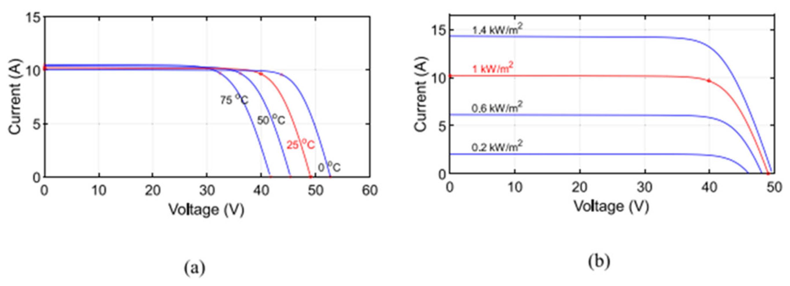
Figure 1. PV module current-voltage curves: (a) Variable PV module temperature; (b) Variable solar irradiance [12].
Preprints 137463 g001
Figure 2. Electrical efficiency as a function of PV module temperature [14].
Preprints 137463 g002
Figure 3. (a) Electrical efficiency as a function of PV module temperature [26]; (b) Current-voltage and power-voltage curves for the PV/PCM module and the standard PV module [27].
Preprints 137463 g003
Figure 4. Single-pass, flat-plane PVT hybrid solar collector with energy performance improvement techniques.
Preprints 137463 g004
Figure 5. Configurations of double-pass PVT hybrid air collectors and techniques for improving their energy performance.
Preprints 137463 g005
Figure 6. Energy conversion of a PV solar cell in a PVT hybrid collector [9].
Preprints 137463 g006
Figure 7. Experimental set-up for forced air circulation in a PVT hybrid collector [26].
Preprints 137463 g007
Figure 8. PVT hybrid air collector with perforated baffles showing the direction of air flow (a) [56] and PVT hybrid air collector with triangular obstacles (b) [58].
Preprints 137463 g008
Figure 9. Configuration of circular ribs under the PV module (a) [59] and geometric configuration with triangular ribs (b) [60].
Preprints 137463 g009
Figure 10. Single-fin channel (a) and multi-fin channel (b) [53].
Preprints 137463 g010
Figure 11. Impinging Jet PV/Thermal Collector: Experimental prototype and schematic [74].
Preprints 137463 g011
Figure 12. Effect of increasing PV module temperature on electrical efficiency in different Reynolds number ranges for finned and finless PVT hybrid air collectors [70].
Preprints 137463 g012
Figure 13. Schematic of the PVT hybrid collector with PCM [79].
Preprints 137463 g013
Figure 14. Schematic of the PVT-SAH dual pass hybrid collector with heat pipes [87].
Preprints 137463 g014
Figure 15. (a) PV module with porous medium as heat exchanger [88] and (b) PV module with honeycomb heat exchanger [92,93].
Preprints 137463 g015
Figure 16. (a) 3D view of the PV/PCM module (b) Cross-sectional view of the PV/PCM module [95].
Preprints 137463 g016
Figure 17. (a) Channel with fin coupling and T-shaped baffles and (b) Channel with fin coupling and V-shaped baffles [50].
Preprints 137463 g017
Figure 18. (a) Radiated PV panel usage concept and (b) radiated PV module thermal analysis diagram [99].
Preprints 137463 g018
Figure 19. Photonic cooling of a PV solar module [100].
Preprints 137463 g019
Figure 20. Schematic of the PVT/TE hybrid collector [104].
Preprints 137463 g020
Figure 21. Schematic of the building-integrated hybrid PVT collector [115].
Preprints 137463 g021
Figure 22. Cross-sectional view of a single pass (a) and a double pass, bifacial hybrid PVT collector [121].
Preprints 137463 g022
Figure 23. Dual-pass configurations of hybrid air PVT collectors (a) and (b) [124].
Preprints 137463 g023
Figure 24. Diagram of the V-groove PVT collector cross-sectional view [90].
Preprints 137463 g024
Figure 25. Schematic of the PVT hybrid collector configurations: (a) double glazing single pass structure with air blade, (b) single glazing single pass structure with air blade, (c) double glazing double pass structure and (d) single-glazed double-pass structure [132].
Preprints 137463 g025
Figure 26. Improvement techniques and factors affecting energy performance of hybrid PVT air solar collectors.
Preprints 137463 g026
Disclaimer/Publisher’s Note: The statements, opinions and data contained in all publications are solely those of the individual author(s) and contributor(s) and not of MDPI and/or the editor(s). MDPI and/or the editor(s) disclaim responsibility for any injury to people or property resulting from any ideas, methods, instructions or products referred to in the content.
Copyright: This open access article is published under a Creative Commons CC BY 4.0 license, which permit the free download, distribution, and reuse, provided that the author and preprint are cited in any reuse.
Alerts
Prerpints.org logo

Preprints.org is a free preprint server supported by MDPI in Basel, Switzerland.

Subscribe

© 2025 MDPI (Basel, Switzerland) unless otherwise stated