Submitted:
28 October 2024
Posted:
29 October 2024
You are already at the latest version
Abstract
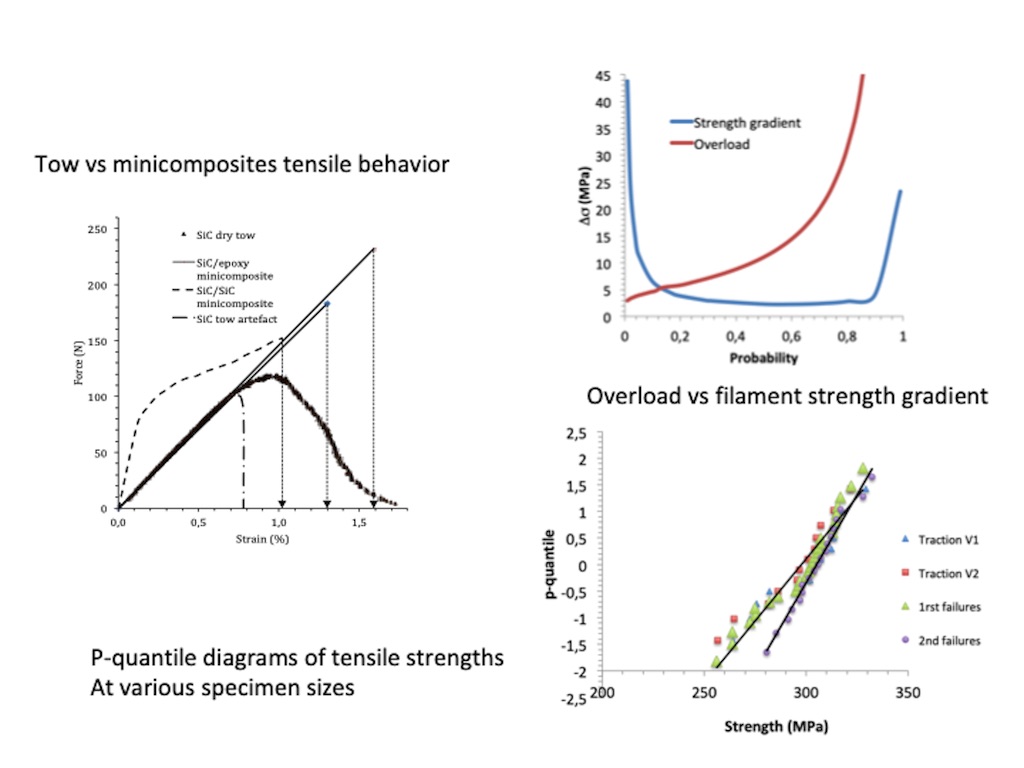
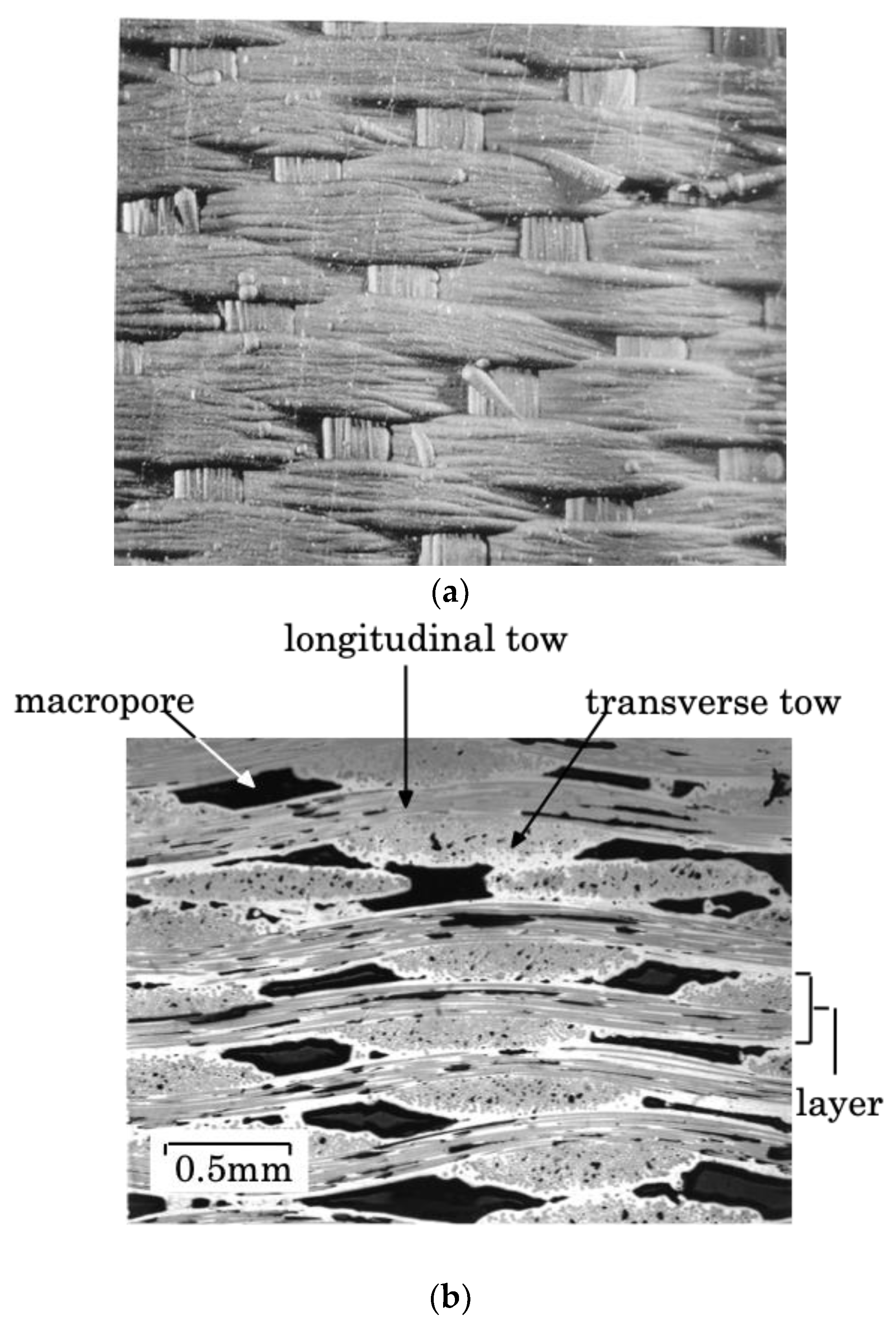
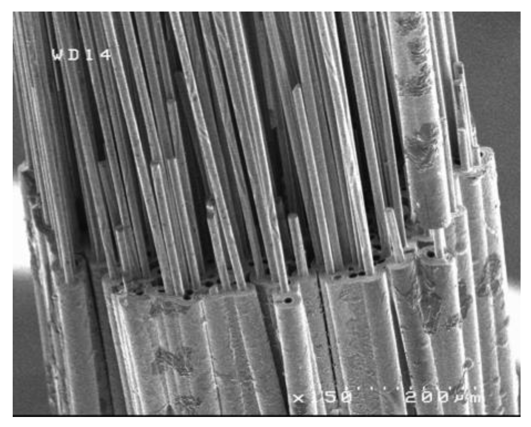
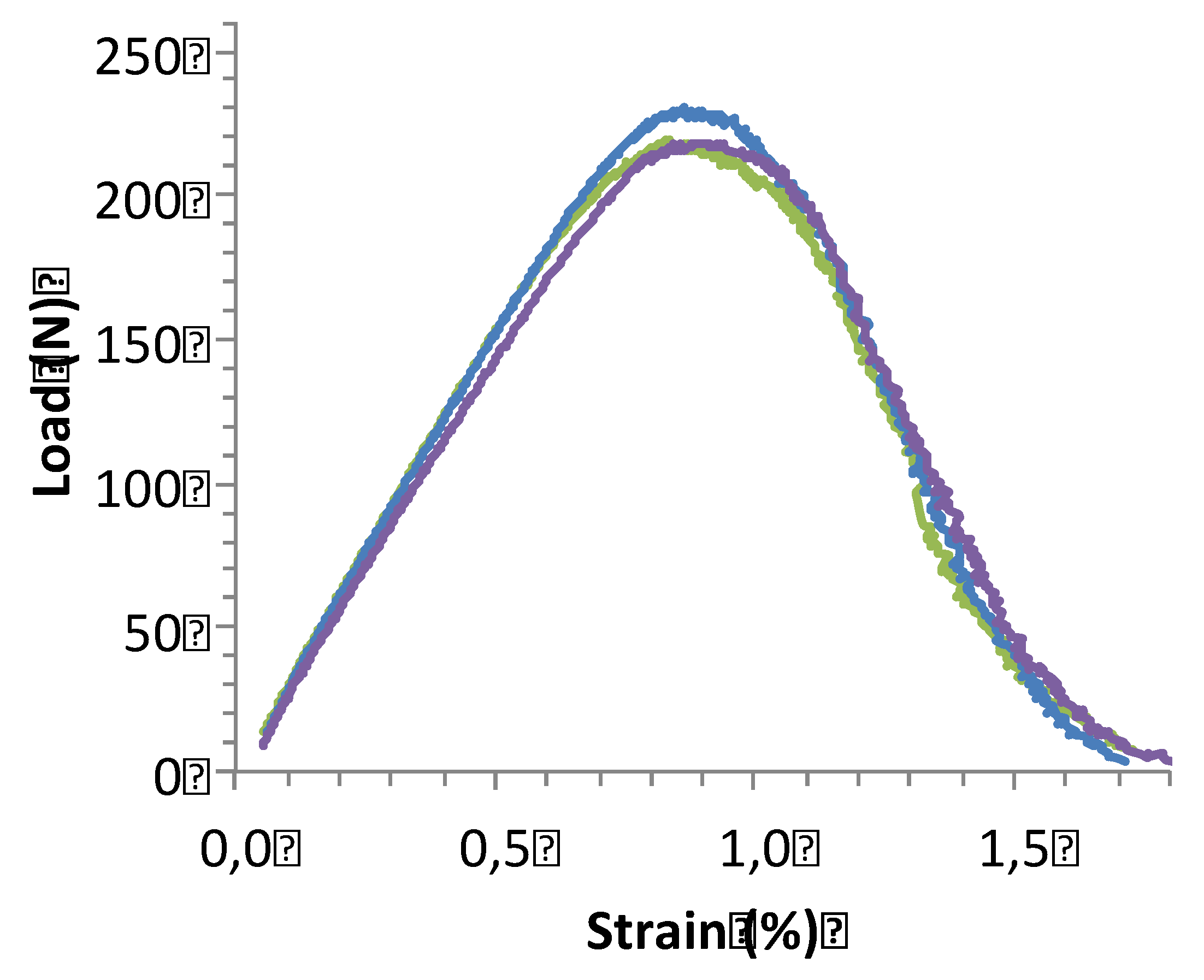
The present paper tackles the important issue of tensile ultimate strength of ceramic matrix composites, using a multiscale approach. The ultimate strength is investigated at the successive increasing length scales inherent to 2D woven SiC/SiC composites, i.e. single filaments, fiber tow, minicomposites reinforced with a single tow, and 2D woven composite. First experimental results on tensile behavior under strain-controlled conditions are summarized for tows, minicomposites and composites. Then, models of tow ultimate failure under controlled force and strain are presented. A criterion of tow failure is developed for filament fracture initiation and then propagation based on applied stress and on filament strength gradient. The model of ultimate failure of minicomposite under strain-controlled condition is based on the strength of filaments in the presence of matrix cracks and the overstress induced by interactions of broken filaments and the matrix. The variability of ultimate strengths of filaments, minicomposites and composites at various gauge lengths is described by linear p-quantile diagrams which indicates that the data follow normal distribution function. The contribution of structural effects to variability of composite and minicomposite strength under strain-controlled loading is analyzed. Their dependence on specimen size is related to reproducibility of critical flaw population and structural effects.
Keywords:
1. Introduction
2. Background: Experimental Tensile Behavior of Filaments, Tows and Composites
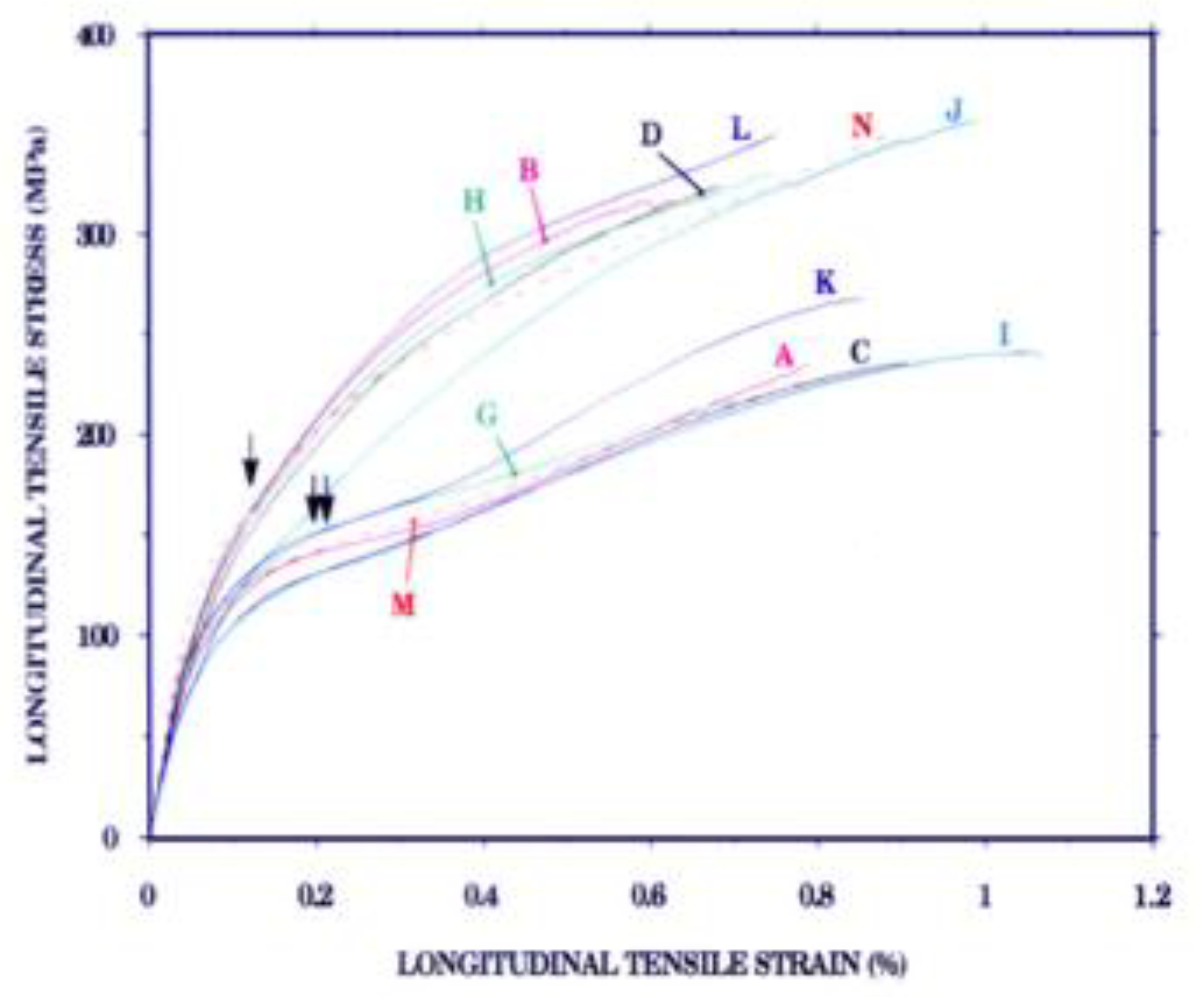
2.1. Multifilament Tows
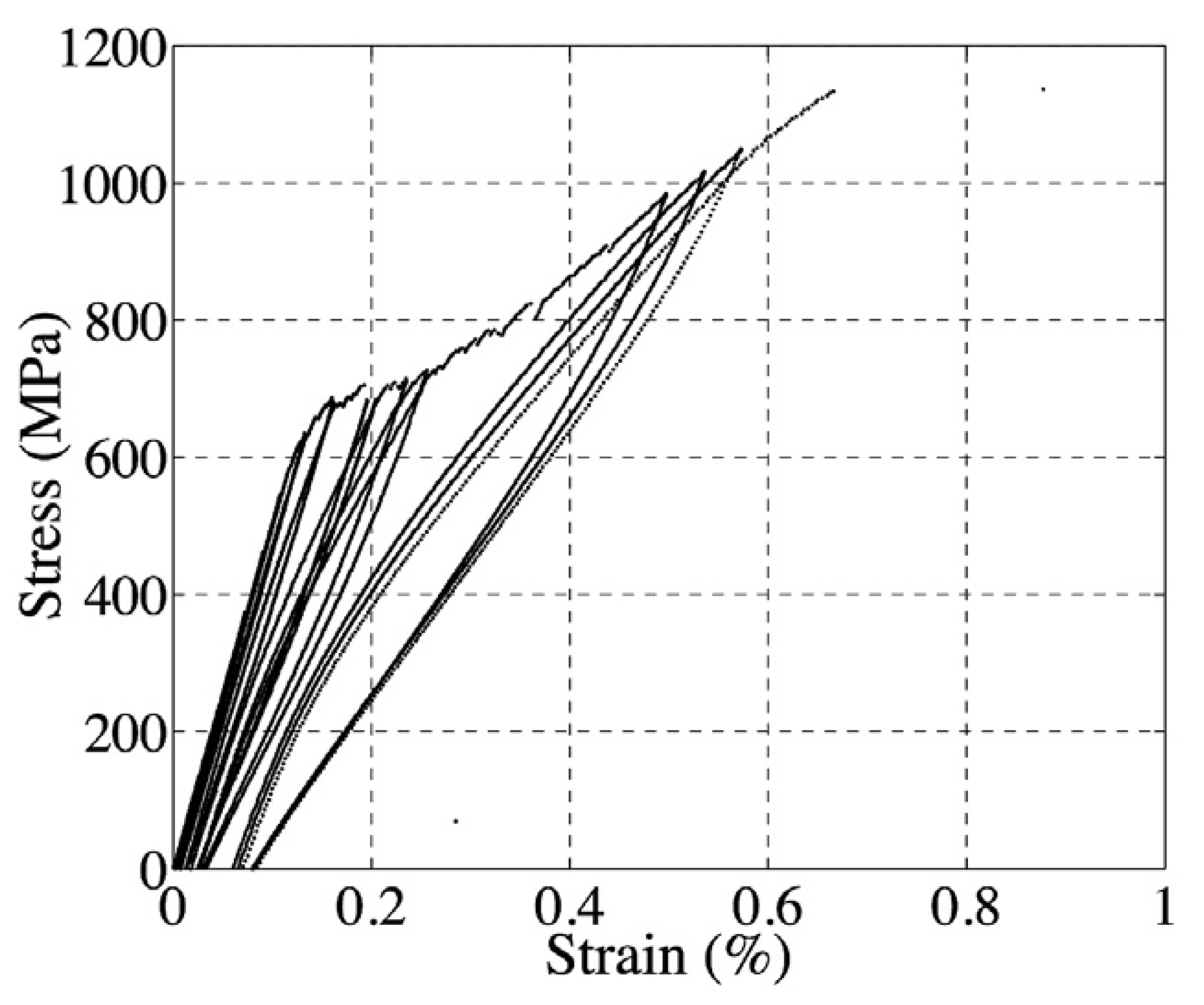
2.2. SiC/SiC Minicomposites
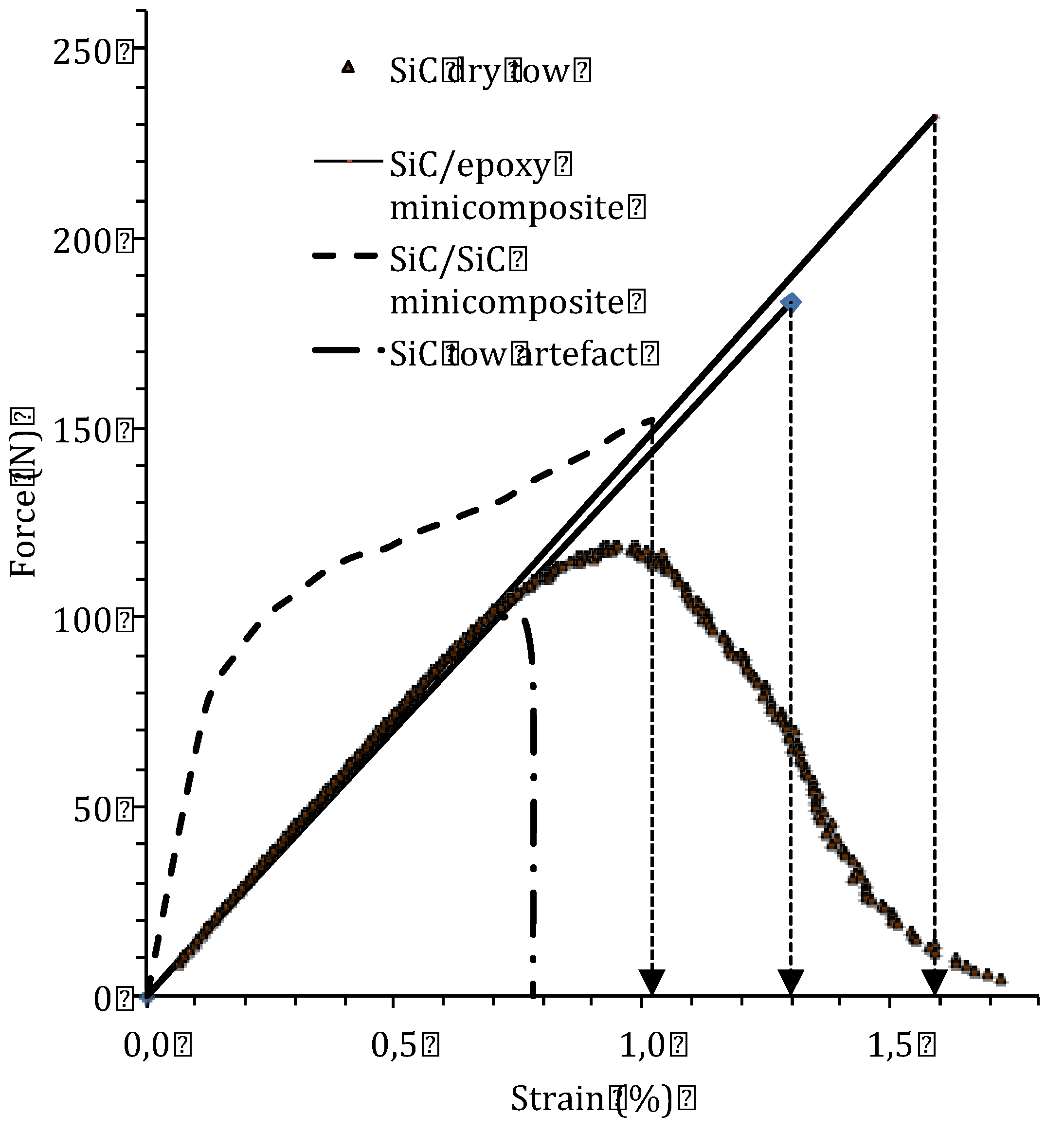
- ⁻ at strains smaller than 0.1%, an initial linear elastic domain.
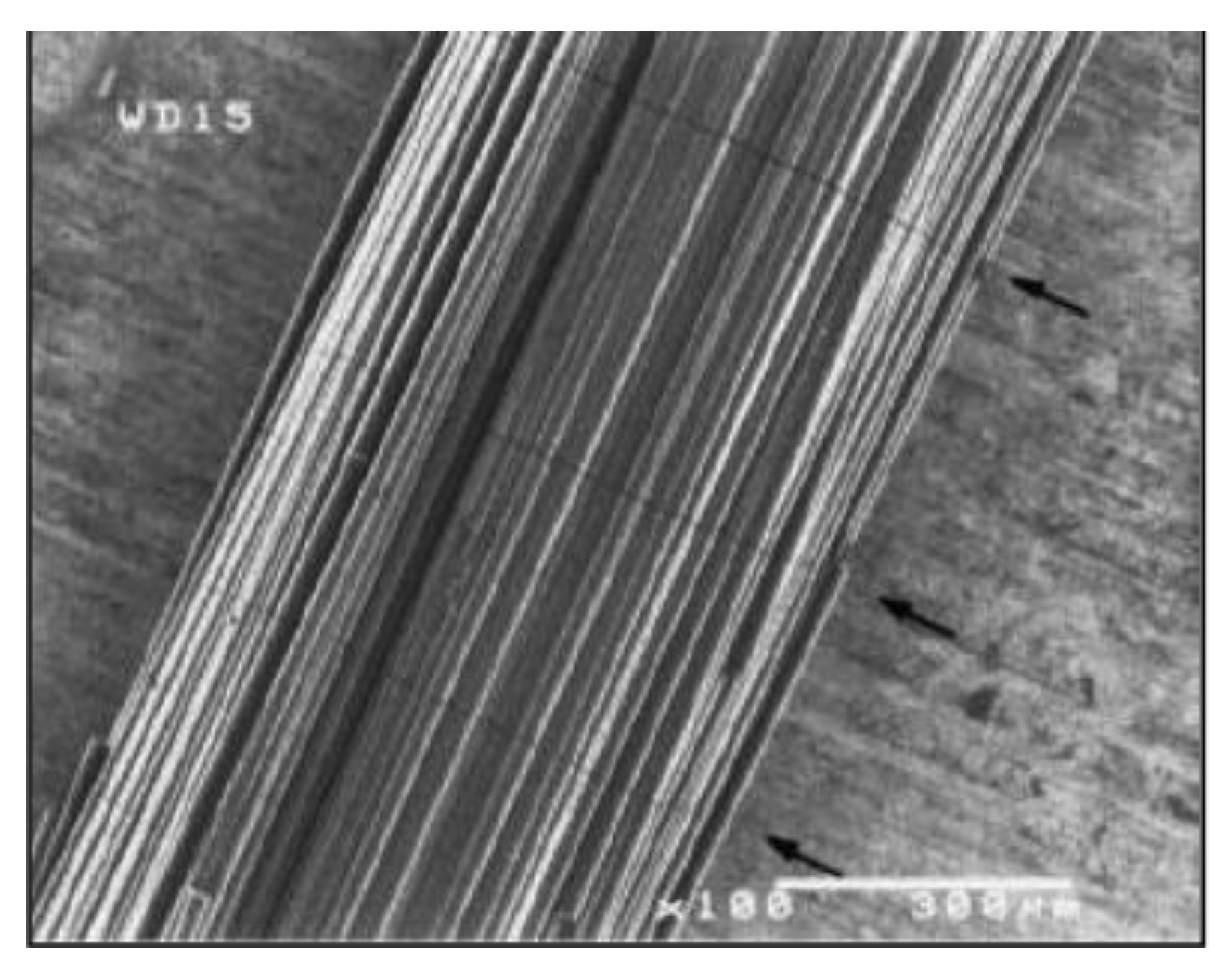
- ⁻ at strains between 0.1% and 0.3%, a non linear domain with upward curvature indicative of increasing compliance, resulting from transverse matrix cracking and associated fiber/matrix debonding (Figure 5).
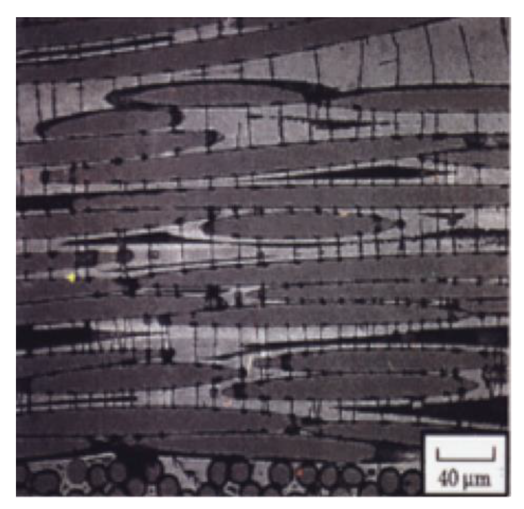
- ⁻ at a strain of about 0.3%, an inflexion point that marks a transition in the damage process from matrix cracking that saturated, to a less severe process such as extension of debonding,
- ⁻ at strains comprised between 0.3% and about 0.7 a second linear domain indicative of constant compliance, that is attributed to deformation of fibres and sliding in the presence of complete debonding.
- ⁻ at strains >0.7%, a non linear domain with upward curvature, indicative of fibre successive failures.
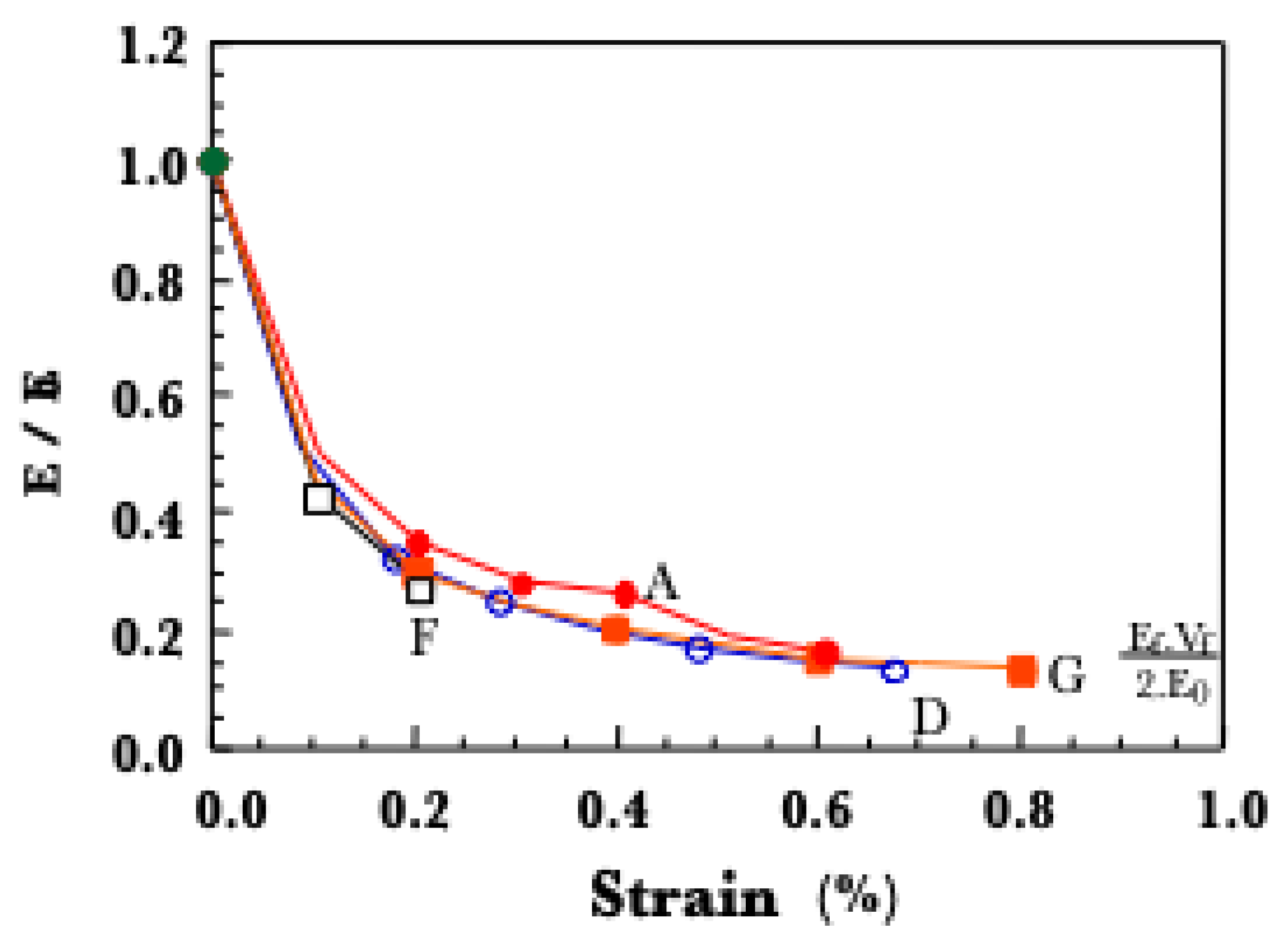
2.4. Scale Level Effect on Behavior Under Strain-Controlled Condition
3. Models of Fracture of Tows and Minicomposites
3.1. Multifilament Tows
3.1.1. Unstable Failure Under Force Controlled Conditions
3.1.2. Stable Failure Under Strain-Controlled Conditions
3.2. Fracture of Minicomposites
3.2.1. Model
3.2.2. Implications
4. Variability of Ultimate Strength
4.1. Characterization of Variability
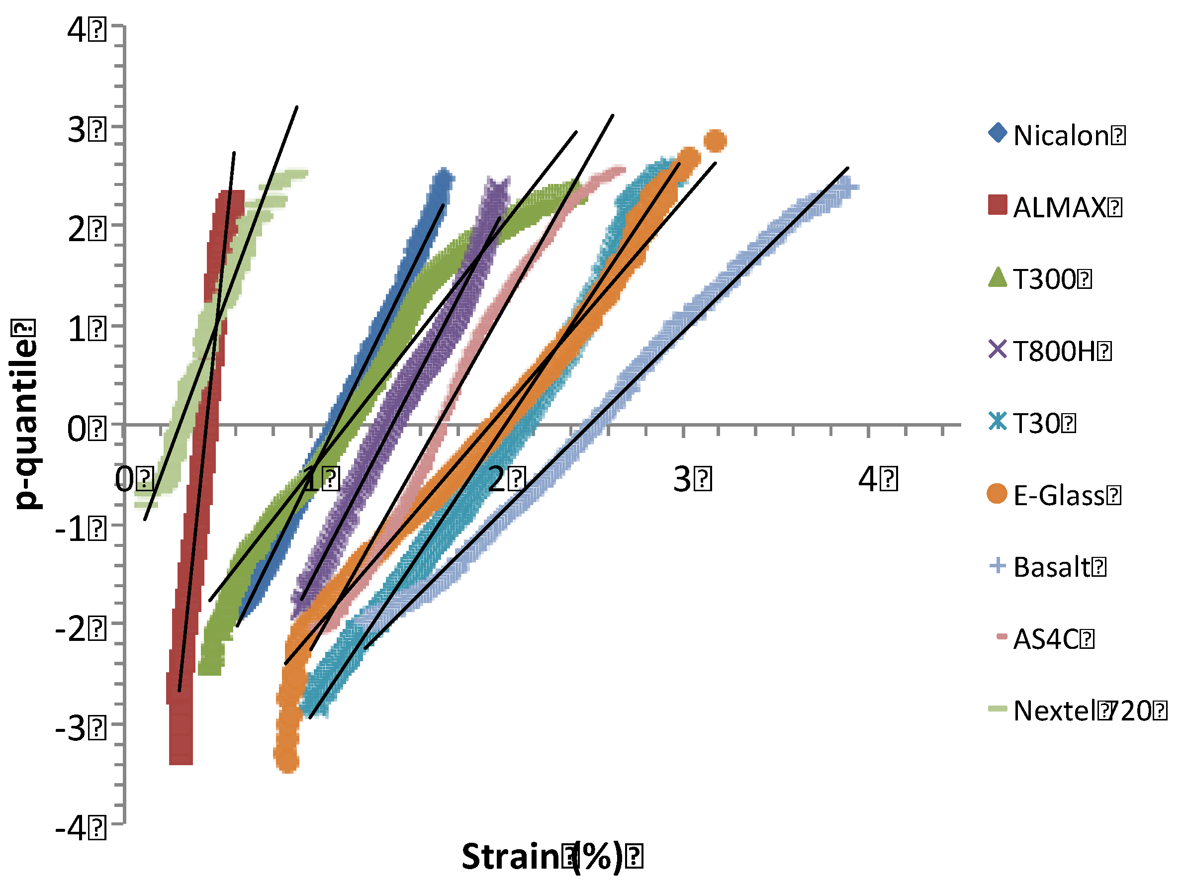
4.2. Filaments
4.3. Fiber Tows
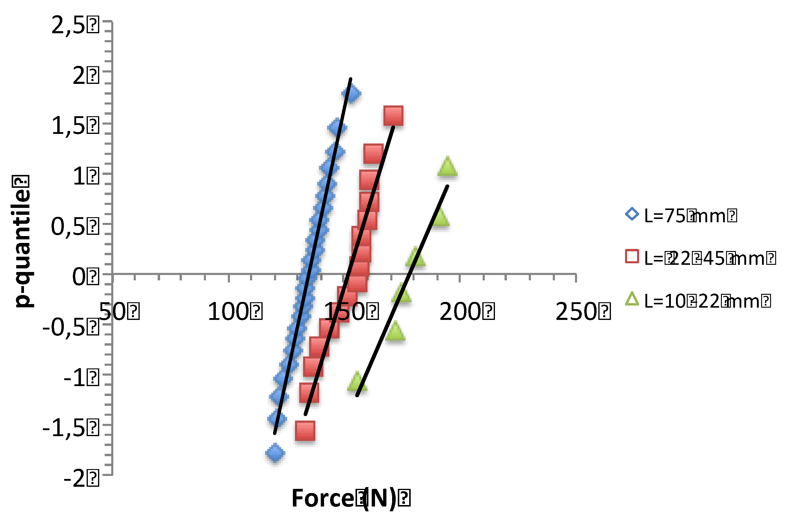
4.4. Minicomposites
4.5. Composite Test Specimens
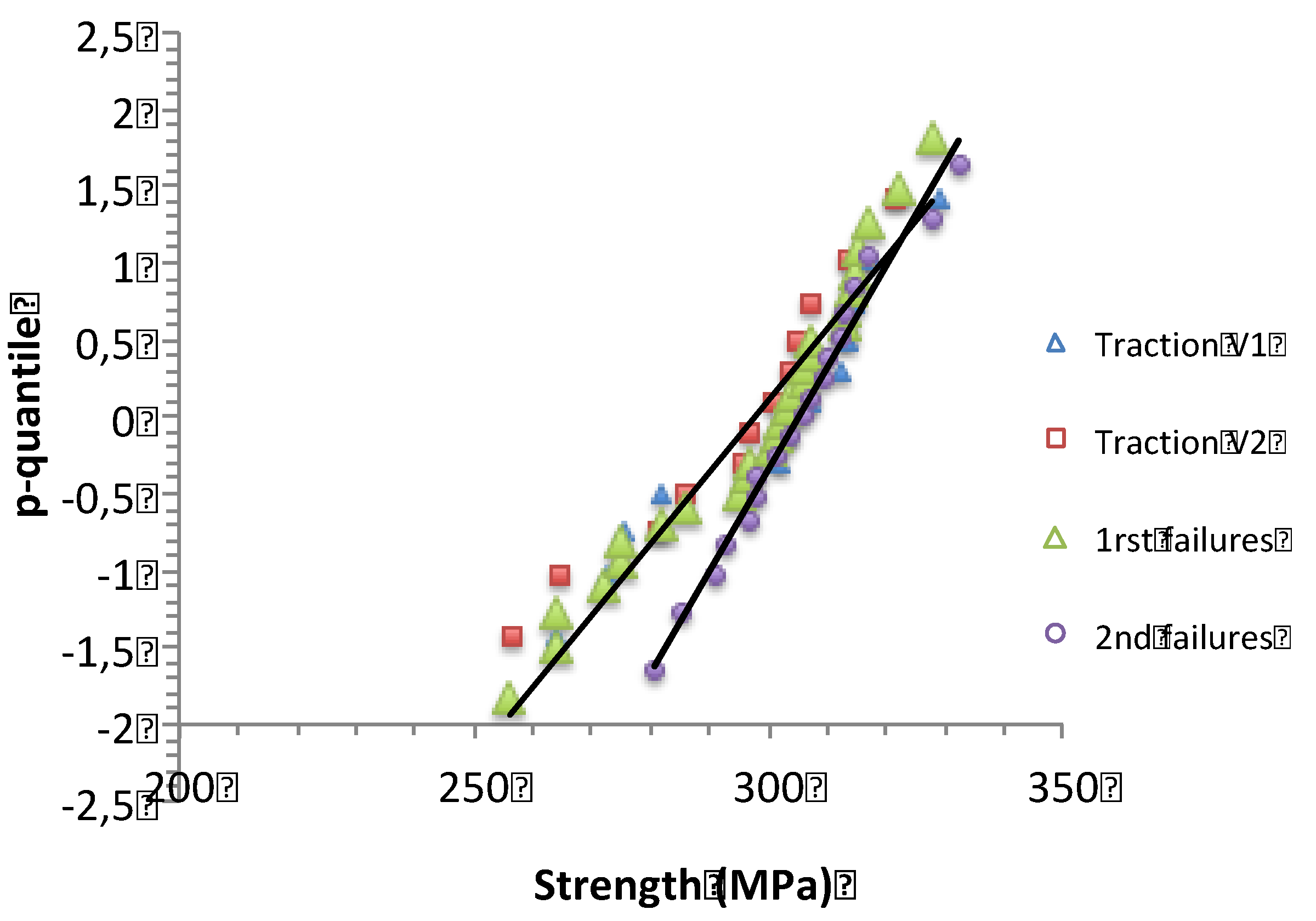
4.5.1. Tensile Strengths
4.5.2. Relation filament vs Composite Strengths
5. Conclusions
Appendix A
Appendix B: p-Quantile Diagrams and Normal Distribution
References
- Lamon. J. Chapter 00152. Properties of characteristics of SiC and SiC/SiC composites,, in Comprehensive Nuclear Materials second edition, Rudy Konings and Stoller (Eds.), Vol.7. pp.400-418, Oxford, 2020, Elsevier LTD.
- Lamon, J. Handbook of Ceramics and Glasses”. Narottam P. Bansal Editor,Kluwer Academic Publishers, New York, USA, Chapter 3, CVI SiC/SiC Composites, 2005 ; pp. 55-76.
- El Yagoubi, J.; Lamon, J. ; Batsale, J-C. ; Le Flem, M. Experimental assessment of damage-thermal diffusivity relationship in unidirectional fiber-reinforced composite under axial tensile test. Acta Materialia.
- Argon, A.S. 1972; 1. [CrossRef]
- Knowles, K.M.; Yang, X. F. Mechanical modeling of the strength and toughness of unidrectional Fiber-Reinforced Ceramics, Ceram. Eng. Sci. Proc. 1991, 12[7-8], 1375-1388.
- Prewo, K.M. Tension and flexural strength of silicon carbide fiber-reinforced glass ceramics, J. Mater. Sci.1986, 21, 3590 – 3600.
- Davidge, R. W.; Briggs, A. The tensile fracture of brittle matrix composites reinforced with unidirectional continuous fibers, J. Mater. Sci. 1989, 24, 2815–2819. [Google Scholar] [CrossRef]
- Schweitert, H. R.; Steif, P. S. A theory for the ultimate strength of a brittle-matrix composite, J. Mech. Phys. Solids 1990, 38[3]325-343.
- Steif, P. S.; Schweitert, H. R. Ultimate strength of ceramic-matrix composites, Ceram. Eng. Sci. Proc. 1990, 11[9-10], 1567-1576.
- Coleman, B. D. On the strength of classical fibers and fiber bundles, J. Mech. Phys. Solids 1958, 60–70. [Google Scholar] [CrossRef]
- Kelly, A.N.; Macmillan, H. Strong Solids, 3rd ed., Clarendon Press, Oxford, U. K., 1986.
- Kendall, K.N. ; Alford, McN.; Birchall, J. D. The strength of fibers in all-ceramic composites, Mat. Res. Soc. Symp. Proc. 1987, 78, 181-187.
- Rosen, B. W. Tensile failure of fibrous composites, AIAA Journal 1991, 2 [11] 1985 – 1991.
- McCartney, L. N. New theoretical model of stress transfer between fiber and matrix in a uniaxially fibre-reinforced composite, Proc. Roy. Soc. Lond. A. 1989, 425, 215 – 244.
- Smith, R. L. A probability model for fibrous composites with local load sharing, Proc. Roy. Soc. Lond. A., 1980, 372, 539 – 553.
- Evans, A.G.; Zok, F. W. Review : the physics and mechanics of fiber-reinforced brittle matrix composites, Journal of Materials Science 1994, 29, 3857-3896.
- Curtin, WA. Stress-strain behavior of brittle matrix composites. In Comprehensive composites materials, Kelly, A., Zweben, C ; Eds.; Elsevier Science Ltd. Great Britain, 2000; Volume 4, pp. 47–76.
- Curtin, WA. Ultimate strengths of fibre-reinforced ceramics and metals. Composites 1993, 24(2), 98–102. [Google Scholar] [CrossRef]
- Lamon, J. Fiber Reinforced Ceramic Matrix Composites: A Probabilistic Micromechanics-Based Approach. In Handbook of Mechanics of Materials, Hsueh, C.-H., et al.; Eds.; Springer Nature, Singapore, 2018; pp. 32. [CrossRef]
- Lamon, J. The unstable fracture of multifilament tows. J. Compos. Sci. 2024, 8, 52. [Google Scholar] [CrossRef]
- Calard,V.; Lamon, J. Faillure of fiber bundles. Composites Science and Technology, 64.
- R’Mili, M.; Murat, M. Caractérisation des fibres par amélioration de l’essai sur mèche avec mesure directe de la déformation. C. R. Acad. Sci. 1989, 314, 355–364. [Google Scholar] [CrossRef]
- R’Mili, M.; Moevus, M.; Godin, N. Statistical fracture of E-glass fibres using a bundle test and acoustic emission monitoring. Comp. Sci. Technol. 2008, 68, 1800–1808. [Google Scholar] [CrossRef]
- R’Mili, M. ; N. Godin, Lamon, J. Flaw strength distributions and statistical parameters for ceramic fibers: The normal distribution. Physical Review E 2012, 85, 1106-1112.
- ISO 22459; Fine Ceramics (Advanced Ceramics, Advanced Technical Ceramics) - Methods of Test for Reinforcements - Determination of Distribution of Tensile Strength and of Tensile Strain to Failure of Filaments within a Multifilament Tow at Ambient Temperature. International Standard Organisation: Geneva, Switzerland, 2020.
- Lamon, J.; R’Mili, M. Investigation of specimen size effects on p-quantile diagrams and normal distributions of critical flaw strengths in fiber tows, J. J. Composites Science. [CrossRef]
- Lamon, J.; R’Mili, M. Investigation of flaw strength distributions from tensile force-strain curves of fiber tows, Composites: Part A 2021, 45, 106262.
- Lissart, N.; Lamon, J. Damage and failure in ceramic matrix minicomposites: exprimental study and model, Acta mater. 1997, 45, 1025-1044.
- Sauder, C.; Brusson, A.; Lamon, J. Influence of interface characteristics on the mechanical properties of Hi-NicalonS and SA3 fiber reinforced SiC/SiC minicomposites. International Journal of Applied Ceramic Technology 2010, 7, 291–303. [Google Scholar] [CrossRef]
- Calard,V.; Lamon, J. A probabilistic approach to the ultimate failure of ceramic-matrix composites-part I: experimental investigation of 2D woven SiC/SiC composites. Composites Science and Technology 2002, 62, 385-393.
- ISO 15733 Fine ceramics (advanced ceramics, advanced technical ceramics) - Mechanical properties of ceramic composites at ambient temperature in air atmospheric pressure -determination of tensile properties. International Standard Organisation: Geneva, Switzerland, 2015.
- Lamon, J.; R’Mili, M. Statistical analysis of ultimate strength of filaments, tows and minicomposites. Journal of Composites Science, 3390. [Google Scholar]
- Daniels, H.E. The statistical theory of the strength of bundles of threads I. Proc. R. Soc. 1945, A183, 405–435. [Google Scholar]
- Phoenix, S.L.; Taylor, H.M. The asymptotic strength distribution of a general fiber bundle. Adv. Appl. Prob. 1973, 5, 200–216. [Google Scholar] [CrossRef]
- Phoenix, S.L. Probabilistic strength analysis of fiber bundles structures. Fiber Science and Technology 1974, 7, 15–31. [Google Scholar] [CrossRef]
- Weibull, W. A. Statistical theory of the strength of materials. R. Swed. Inst. Eng. Res. 1939, 151, 1–45. [Google Scholar]
- Guillaumat, L.; Lamon, J. Fracture statistics applied to modelling the nonlinear stress-strain behavior in microcomposites : influence of interfacial parameters. Int. J. of Fracture, 1996. [Google Scholar]
- McCartney, L.N.; Smith, R.L. Statistical theory of the strength of fiber bundles. ASME Journal of Applied Mechanics 1983, 105, 601–8. [Google Scholar] [CrossRef]
- Gurvich, M.; Pipes, R. Strength size effect of laminated composites. Comp Science and Technology 1995, 55, 93–105. [Google Scholar] [CrossRef]

| Fiber type | grain size (nm) | surface roughness RRMS(nm) | strain-to-failure minicomposite (%) | strain-to-failure 2D SiC/SiC (%) | ε(αc) (%) |
|---|---|---|---|---|---|
| Tyranno SA3 | 50-100 | 8.04 [29] | < 0.4 | 0.5 | |
| Hi Nicalon S | 20 | 2.33 [29] | <0.6 | 0.8 | |
| Hi Nicalon | 10 | <0.9 | 0.8 | ||
| Nicalon | 5 | <1 | < 1.1 | 0.9 |
| mean | standard deviation | Weibull modulus | characteristic strength | CV | |
| Nicalon filaments (MPa) | 2088 | 432 | 5 | 2196 | 0.21 |
| Tows | N/A | N/A | N/A | N/A | |
| Minicomposites (N) | |||||
| first failure | 135 N | 8.4 N | 19.2 | 139 N | 0.06 |
| second failure | 152 N | 11.3 N | 16.2 | 157 N | 0.074 |
| third failure | 178 N | 14.2 N | 15.1 | 184 N | 0.079 |
| Composite (MPa) | |||||
| V1 | 299.4 | 20.74 | 17.32 | 380.7 | 0.069 |
| V2 | 294.4 | 19.24 | 18.35 | 303.2 | 0.065 |
| first failures | 297.7 | 18.95 | 18.85 | 306.25 | 0.064 |
| second failures | 305.13 | 18.28 | 27.57 | 311.35 | 0.060 |
Disclaimer/Publisher’s Note: The statements, opinions and data contained in all publications are solely those of the individual author(s) and contributor(s) and not of MDPI and/or the editor(s). MDPI and/or the editor(s) disclaim responsibility for any injury to people or property resulting from any ideas, methods, instructions or products referred to in the content. |
© 2024 by the authors. Licensee MDPI, Basel, Switzerland. This article is an open access article distributed under the terms and conditions of the Creative Commons Attribution (CC BY) license (http://creativecommons.org/licenses/by/4.0/).


