Preprint
Article

On the Performance of RIS-NFC for mmWave Communications

Altmetrics

Downloads

44

Views

22

Comments

0

This version is not peer-reviewed

Submitted:

28 October 2024

Posted:

30 October 2024

You are already at the latest version

Alerts
Abstract
Utilizing reconfigurable intelligent surfaces (RIS) equipped with numerous passive reflecting elements to control wireless communication environment has garnered significant interest from both academic and industrial circles. In this paper, we study the performance of RIS-aided wireless communication systems based on the path loss model in lower frequency band and mmWave band. Based on the proposed model, it is difficult to directly study and obtain the closed-form expressions for the achievable capacity, since that millimeter- wave (mmWave) band may lead to the near-field communication (NFC) environment. Consequently, the upper bound of the achievable capacity are analysed with Hölder inequality in NFC. Simulation and analytical results indicate the correctness of our derived expressions, which shows that the RIS elements number, the RIS elements length, and the angle of signals transmitting from RIS to user can affect the upper bound of achievable capacity for our proposed system.
Keywords: 
Subject: Computer Science and Mathematics  -   Computer Networks and Communications

1. Introduction

As wireless communication technology continues to advance rapidly, researchers have begun to shift their focus on the emerging sixth-generation (6G) communication systems. To meet the demanding requirements of 6G, several promising technologies have been proposed, in which includes extremely-large multiple-input multiple-output (XL-MIMO), artificial intelligence (AI), millimeter-wave (mmWave) communication, and reconfigurable intelligent surfaces (RIS). Among all prominent candidates, RIS has recently been envisioned as one of the most promising techniques for the future 6G communication systems [1]. RIS is a metal panel consisting of numerous passive, low-cost reflecting surfaces, each capable of dynamically altering the communication channel environment to ensure high-quality information transmission, even in complex and variable scenarios [2].
Currently, researchers have extensively investigated various aspects related to RIS applications, including channel measurement and modeling, channel estimation, beamforming design, as well as the enhancement of system performance. Furthermore, they have developed into the integration of drones, including integrated sensing and communication (ISAC), deep learning (DL) and unmanned aerial vehicle (UAV). For example, [3] aimed to tackle the issues related to the wireless channel and modeling of RIS-aided systems. The optimization of achievable rates in RIS-assisted broadband systems was investigated in [4]. A novel sensing RIS structure which is efficient for hardware implementation was presented in [5], and the perspective of CSI acquisition is compared with other RIS structures. [6] investigated an innovative RIS-assisted system which utilized the mobile edge computing (MEC). In this system, users can optimize RIS reflection coefficients to minimize energy consumption by integrating simultaneous wireless information and power transfer (SWIPT). Thereby it is able to effectively support the signal energy harvesting, as well as the task offloading. By deploying RIS, the performance of the multiple access channel (MAC) with non-casually known side information in the system with two-user was analyzed in [7]. By maximizing the signal power of the relevant path, the closed-form solutions were obtained with active and passive beamformings in [8], and a deterministic approximate expression for the ergodic capacity was also derived, which depends on the association coefficients and RIS deployment locations. The beyond diagonal orthogonal frequency division multiplexing (OFDM) system, where the RIS was deployed, was derived in [9], and the novel capacity expression began with the fundamental principles of the system is obtained, which provides unique propagation path of the cascaded channels.
However, the majority of aforementioned researches on RIS have concentrated on the communication system of plane wave model. As the transmission frequency band is elevated, the Rayleigh distance changes accordingly, which may lead to the traditional plane wave model becoming inadequate [10]. The phase changes of the signals arriving at different RIS elements cannot be ignored and far-filed modeling method becomes no longer accurate [11]. Consequently, the near-field spherical wave model becomes a significant focus in RIS research. The optimization of achievable rates in RIS-assisted near-field broadband systems was investigated in [4]. In [12], the authors studied the localization for user, while the RIS deployed in proposed system can reflect and receive signals simultaneously in the near field region, with the Cramer-Rao lower boundary utilized to evaluate the localization performance. [13] designed codebooks and beam training schemes in cross near and far field regions and the near field region for downlink MIMO RIS-aided systems, which were used for RIS reflecting coefficient optimization. The authors of [14] proposed a channel model, which was studied with the Green’s function method. The authors carried out the performance analysis of near field for not only the general RISs but also STAR-RISs. [15] conducted a comprehensive study for the case of near-field, while the case of far-field was also investigated. The results in [15] proved that the loss of information would occur with the incorrect application of the far-field propagation in near-field channel model.
Specially in mmwave communication, the traditional plane wave model may transform into a spherical wave model. Therefore, RIS-assisted systems and mmWave communications are increasingly seen as key components for future 6G networks. For instance, [16] studied a RIS-aided network working with mmWave and proposed a channel estimation method with low-complexity, leveraging the assumption of the spherical electromagnetic waves. In addition, [17] introduces efficientchannel estimation techniques for MIMO systems with wideband of mmWave, utilizing extremely large-scale RIS and working in the near-field region. Furthermore, [18] examines the system performance, in which the mmWave was utilized, the localization of user was in the near field region and an HRIS was deployed. In addition, the authors proposed a strategy based on IER, aiming to reduce the worst-case CRLB with the optimization of the phase position uncertainty set. The main contributions of this letter are provided as follows:
  • We proposed and study the RIS-aided wireless communication system with the path loss model working in lower frequency band and mmWave band, which considers projected aperture, power radiation pattern, the number and the length of RIS elements, as well as elevation and azimuth angles of BS and user. Furthermore, the upper bound expressions of achievable capacity are derived, respectively.
  • The impacts of RIS element number and RIS element length on the achievable capacity are studied by utilizing the upper bound expressions. Simulation results indicate that the achievable capacity is significantly improved by increasing the element number or the element dimension of RIS in both lower frequency band and mmWave band. In addition, we illustrate the results of the achievable capacity as a function of the elevation angle from center of the RIS to the user.

2. System Model
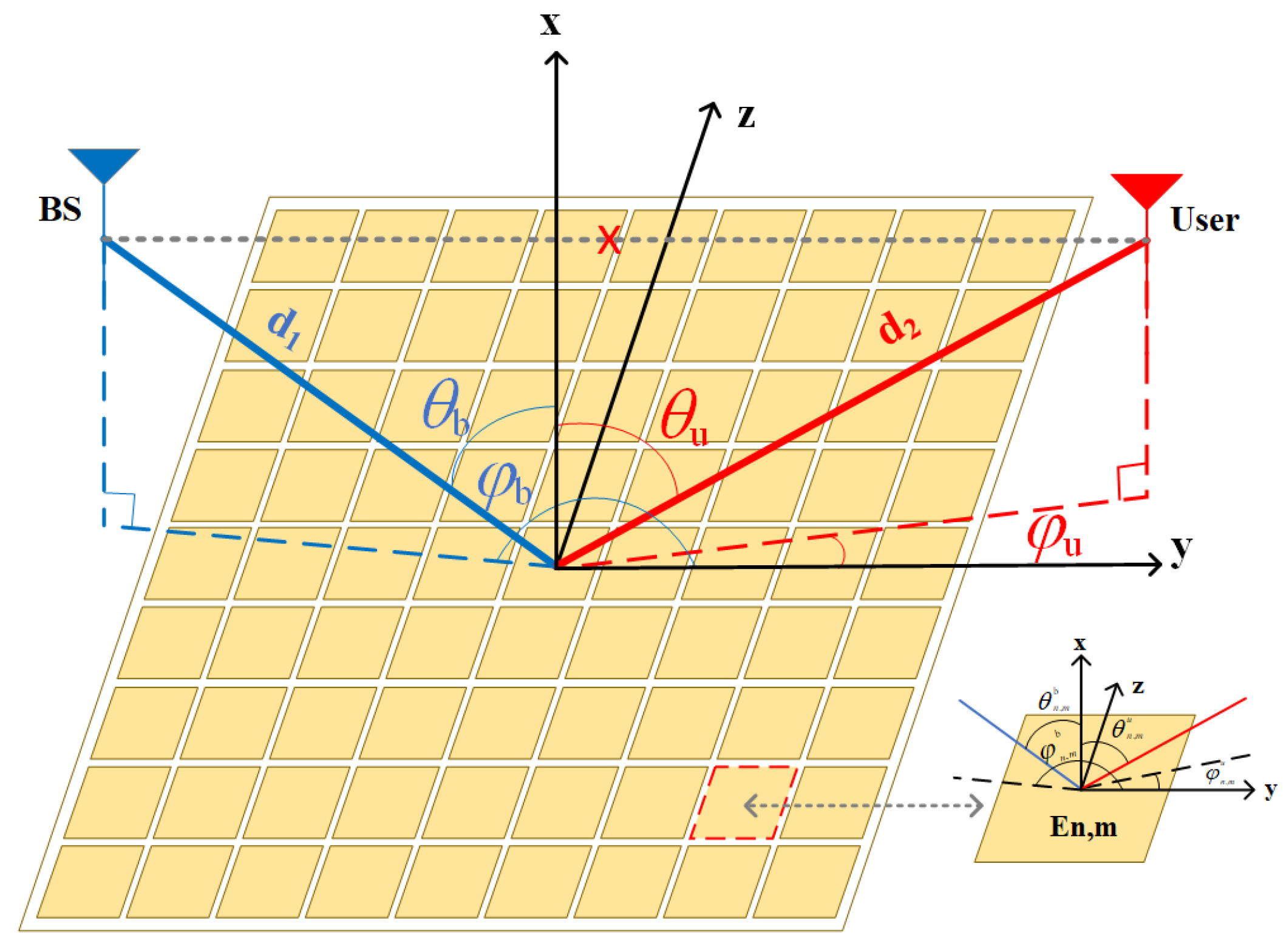
In this work, we consider a RIS-assisted wireless communication system composed of one base station (BS) with a single antenna, one User with a single antenna and a RIS, where the direct BS-user link is blocked due to obstacles or out of transmission scope, as shown in Figure 1. RIS is positioned, in which the geometric center is the origin of the Cartesian coordinate system’s y z plane, and the RIS array consists of N elements, arranged uniformly in rows and columns, where N is considered as an odd number. The size of each unit cell along y axis and z axis is d. Let E n , m represent the RIS element situated in the n-th row and m-th column. In addition, we also assume that the reflection coefficient for E n , m can be written as β n , m e j α n , m , with β n , m and α n , m denoting the amplitude shift and phase shift of signals on each reflecting element. Thus, the signals received at user is expressed as
y = P t h 1 T Θ h 2 s + n ,
in which Θ = diag { β 1 , 1 e j α 1 , 1 , β 1 , 2 e j α 1 , 2 , , β n , m e j α n , m } for m = 1 , , N and n = 1 , , N , represents the RIS reflection matrix. In this context, h 1 and h 2 is the channel between BS and RIS and the channel between RIS and user, P t denotes the transmit power, s denotes the desired signal, as well as n is the additive white Gaussian noise (AWGN).
Figure 1. RIS-NFC system with a large-scale array number of RIS elements.
Preprints 137678 g001
Taking the core of RIS elements as the origin of coordinate, we make the coordinates of the element of RIS which is deployed on the n-th row and m-th column be r n , m R I S = ( 0 , m d , n d ) , where m [ ( N 1 ) 2 , ( N 1 ) 2 ] and n [ ( N 1 ) 2 , ( N 1 ) 2 ] . The fixed distance between the transmitter and RIS is d 1 and the fixed distance from the RIS to receiver is d 2 . In this paper, we investigate the condition of d 1 < d 2 . The symbols θ b , φ b , θ u , and φ u are used to denote the elevation and azimuth angles of the transmit signals between RIS and BS, and that of signals between RIS and user, respectively. Let θ n , m b , φ n , m b , θ n , m u and φ n , m u denote the elevation angle and the azimuth angle from E n , m to BS, the elevation angle and the azimuth angle from E n , m to user, respectively. Let θ n , m b , φ n , m b , θ n , m u , and φ n , m u denote the elevation and azimuth angles between BS and element E n , m , as well as the elevation and azimuth angles between user and element E n , m . The positions of BS and user are expressed as r B S = ( d 1 sin θ b cos φ b , d 1 sin θ b sin φ b , d 1 cos θ b ) and r u s e r = ( d 2 sin θ u cos φ u , d 2 sin θ u sin φ u , d 2 cos θ u ) . Consequently, the distance between the base station and element E n , m is given as
d n , m 1 = r n , m R I S r b s = d 1 1 2 m ϱ 1 s i n θ b s i n φ b 2 n ϱ 1 c o s θ b + κ ϱ 1 2 .
Similarly, the distance between element E n , m and destination is given as
d n , m 2 = r u s e r r n , m R I S = d 1 1 2 m ϱ 2 s i n θ u s i n φ u 2 n ϱ 2 c o s θ u + κ ϱ 2 2 ,
where κ = m 2 + n 2 , ϱ 1 = d d 1 , ϱ 2 = d d 2 , and ϱ i < < 1 ( i = 1 , 2 ) .
Furthermore, we denote the normalized power radiation pattern for both BS and User, as well as for each unit cell. With power P t , BS transmits the signals to the elements of RIS by using an antenna characterized by the beam pattern F b ( θ , φ ) and its corresponding antenna gain G t . The received signal is reflected by RIS and received at user, whose antenna has a beam pattern of F u ( θ , φ ) with its corresponding antenna gain of G r . AAs a result, the normalized power radiation pattern is expressed as
F ( θ , φ ) = ( cos θ ) ω , θ [ 0 , π 2 ] , φ [ 0 , 2 π ] , 0 , θ ( π 2 , π ] , φ [ 0 , 2 π ] .
In Eq.(4), ω = G t 2 1 corresponds to F b ( θ , φ ) for BS, while ω = G r 2 1 represents F u ( θ , φ ) for User. When ω = 1 , it denotes F ( θ , φ ) for each unit cell.
The distance used to differentiate the near and far field regions is commonly referred as Rayleigh Distance. This boundary distance is defined as D R e l a y = 2 D 2 λ , in which λ = c / f is wavelength of the transmit signal and D = N 2 d 2 is the maximum dimension of each antenna. In the conventional RIS-assisted far-field communication model, a plane wave model is typically used for channel modeling. However, with the increase of frequency, the probability increases when both of BS and user are situated within Rayleigh distance. Therefore, performance analysis and discussion are provided for lower frequency band and millimeter wave band in next sections.

3. Performance Analysis

In this section, the upper bound of the achievable capacity for RIS-assisted communication system under pass loss modeling channel will be analyzed in lower frequency band and mmwave band, respectively.

3.1. Performance for f < c d 2 2 N 2 d 2 in Far Field

Assuming f 1 represents the lower frequency band, when f = f 1 , BS and User are located in far filed. Both the electromagnetic wave of BS-RIS propagation and electromagnetic wave of RIS-user propagation are used a plane wave model for channel modeling. As observed in [19], it is reasonable to assume the signal directions from antennas on BS and user be aligned with the reflecting elements core of RIS. In consideration of the RIS reflecting elements projected aperture, we can make the path loss from BS to element E n , m be described as
P L n , m 1 = 4 π ( d 1 ) 2 G t F ( θ b , φ b ) · 1 d 2 ( r b s ) T · A r b s = 4 π ( d 1 ) 2 G t F ( θ b , φ b ) d 2 s i n θ b c o s φ b ,
P L n , m 2 = 4 π ( d 2 ) 2 G r F ( θ u , φ u ) · 1 d 2 ( r u s e r ) T · A r u s e r = 4 π ( d 2 ) 2 G r F ( θ u , φ u ) d 2 s i n θ u c o s φ u .
In the far field region, the BS-RIS channel coefficient and the RIS-user channel coefficient can be represented as
h n , m 1 = 1 P L n , m 1 e j 2 π f 1 c d 1 , h n , m 2 = 1 P L n , m 2 e j 2 π f 1 c d 2 .
The total channel coefficient matrix for the RIS-assisted communication system is obtained as h = ( h 2 ) T Θ h 1 , and we set the weight coefficient matrix of the MRC algorithm to be ξ = h / | | h | | and | | ξ | | = 1 . The signal-to-noise ratio (SNR) in the far field can be given as
γ = P t σ 2 n = N 1 2 N 1 2 m = N 1 2 N 1 2 ν e j 2 π c f 1 d 1 + d 2 β n , m e j α n , m 2 ,
where ν = 1 P L n , m 1 P L n , m 2 . The achievable capacity in far -field system is given as C f a r f i e l d = 1 2 l o g 2 ( 1 + γ ) . Similarly, the phase of the RIS array elements is set to α n , m = 2 π f 1 ( d 1 + d 2 ) / c , and by setting the amplitude of the RIS array elements β 1 , 1 . . . . . . β n , m = 1 , each term can achieve its maximum value. The maximum achievable capacity can be achieved as
C f a r f i e l d m a x = log 2 1 + P t σ 2 n = N 1 2 N 1 2 m = N 1 2 N 1 2 1 P L n , m 1 P L n , m 2 2 .
Consequently, we have maximum achievable capacity in the far field as
C f a r f i e l d u p p e r = log 2 P t σ 2 G t G r N 4 d 4 s i n θ b s i n θ u c o s φ b c o s φ u c o s θ b c o s θ u 16 π 2 d 1 2 d 2 2 .

3.2. Performance for f > c d 2 2 N 2 d 2 in Near Field

However, assuming f 2 represents the mmwave band, when f = f 2 , BS and User are located in near-filed, in which the BS-RIS channeland the RIS-user channelare used a spherical wave model for channel modeling. Based on previous research [11], the path loss between the BS and E n , m are expressed as
P L n , m 1 = 4 π ( d n , m 1 ) 2 G t F b ( θ n , m b , φ n , m b ) F ( θ n , m b , φ n , m b ) · 1 d 2 ( r b s r n , m R I S ) T I r b s r n , m R I S = 4 π ( d n , m 1 ) 3 G t F b ( θ n , m b , φ n , m b ) F ( θ n , m b , φ n , m b ) d 2 d 1 s i n θ b c o s φ b ,
and
P L n , m 2 = 4 π ( d n , m 2 ) 2 G r F u ( θ n , m u , φ n , m u ) F ( θ n , m u , φ n , m u ) · 1 d 2 ( r u s e r r n , m R I S ) T I r t r n , m R I S = 4 π ( d n , m 2 ) 3 G r F u ( θ n , m u , φ n , m u ) F ( θ n , m u , φ n , m u ) d 2 d 2 s i n θ u c o s φ u .
The BS-RIS channel coefficient and the RIS-user channel coefficient in near field can be represented as follows
h n , m 1 = 1 P L n , m 1 e j 2 π f 2 c d n , m 1 , h n , m 2 = 1 P L n , m 2 e j 2 π f 2 c d n , m 2 .
The total channel coefficient matrix for the RIS-assisted communication system is obtained as h = ( h 2 ) T Θ h 1 . Similarly, we set the weight coefficient matrix of the MRC algorithm to be ξ = h / | | h | | and | | ξ | | = 1 . The SNR for the RIS-assisted BS-RIS-User communication link in the near field can be calculated by
γ = P t σ 2 n = N 1 2 N 1 2 m = N 1 2 N 1 2 ν e j 2 π c f 2 d n , m 1 + d n , m 2 β n , m e j α n , m 2 ,
where ν = 1 P L n , m 1 P L n , m 2 . The achievable capacity in near-field system is given as C n e a r f i e l d = 1 2 l o g 2 ( 1 + γ ) . Similarly, the phase of the RIS array elements is set to α n , m = 2 π f 2 ( d n , m 1 + d n , m 2 ) / c , and by setting the amplitude of the RIS array elements β 1 , 1 , . . . , β n , m = 1 , the achievable capacity can be achieved as
C n e a r f i e l d m a x = log 2 ( 1 + P t σ 2 n = N 1 2 N 1 2 m = N 1 2 N 1 2 1 P L n , m 1 P L n , m 2 2 ) .
By using Hölder inequality, the upper bound can be obtained as
C n e a r f i e l d m a x log 2 [ 1 + P t σ 2 ( n = N 1 2 N 1 2 m = N 1 2 N 1 2 | 1 P L n , m 1 | 2 × n = N 1 2 N 1 2 m = N 1 2 N 1 2 | 1 P L n , m 2 | 2 ) ] = C n e a r f i e l d u p p e r .
By using [20], we can simplify the previous double integrals as
n = N 1 2 N 1 2 m = N 1 2 N 1 2 | 1 P L n , m 1 | 2 = G t d 2 sin θ b cos φ b 4 π d 1 2 n = N 1 2 N 1 2 m = M 1 2 M 1 2 F b ( θ n , m b , φ n , m b ) F ( θ n , m b , φ n , m b ) 1 2 m ϱ 1 sin θ b sin φ b 2 n ϱ 2 cos θ b + κ ( ϱ 1 ) 2 3 G t F 1 4 π [ arctan ( ( £ 1 Ω 1 ) ( £ 1 c o s θ b ) Ω 1 Ω 1 2 + ( £ 1 Ω 1 ) 2 + ( £ 1 c o s θ b ) 2 ) + arctan ( ( £ 1 + Ω 1 ) ( £ 1 c o s θ b ) Ω 1 Ω 1 2 + ( £ 1 + Ω 1 ) 2 + ( £ 1 c o s θ b ) 2 ) + arctan ( ( £ 1 Ω 1 ) ( £ 1 + c o s θ b ) Ω 1 Ω 1 2 + ( £ 1 Ω 1 ) 2 + ( £ 1 + c o s θ b ) 2 ) + arctan ( ( £ 1 + Ω 1 ) ( £ 1 + c o s θ b ) Ω 1 Ω 1 2 + ( £ 1 + Ω 1 ) 2 + ( £ 1 + c o s θ b ) 2 ) ] ,
where £ i = N d / 2 d i ( i = 1 , 2 ) , Ω 1 = s i n θ b c o s φ b and
F 1 = F b ( θ n , m b , φ n , m b ) F ( θ n , m b , φ n , m b ) .
Similarly, we can simplify the latter double integrals, where Ω 2 = s i n θ u c o s φ u and
F 2 = F u ( θ n , m u , φ n , m u ) F ( θ n , m u , φ n , m u ) .
Let U 1 = £ 1 Ω 1 , U 2 = £ 1 + Ω 1 , U 3 = £ 1 c o s θ b , U 4 = £ 1 + c o s θ b and V 1 = £ 2 Ω 2 , V 2 = £ 2 + Ω 2 , V 3 = £ 2 c o s θ u , V 4 = £ 2 + c o s θ u . After defining
T ( U 1 , U 3 ) = a r c t a n ( U 1 U 3 / Ω 1 Ω 1 2 + U 1 2 + U 3 2 ) ,
and
S ( V 1 , V 3 ) = a r c t a n ( V 1 V 3 / Ω 2 Ω 2 2 + V 1 2 + V 3 2 ) ,
these formulas are valid, and similar definitions apply to other functions. Consequently, we have the upper bound of the achievable capacity in near field as
C n e a r f i e l d u p p e r = log 2 [ 1 + P t σ 2 G t G r 16 π 2 · ( F 1 F 2 ) m a x × T ( U 1 , U 3 ) + T ( U 2 , U 3 ) + T ( U 1 , U 4 ) + T ( U 2 , U 4 ) ( S ( V 1 , V 3 ) + S ( V 2 , V 3 ) + S ( V 1 , V 4 ) + S ( V 2 , V 4 ) ) 1 ] .

4. Numerical Results

In this section, the analytical results are conducted to be proved with simulations. Firstly, the analytical results have been conducted based on Eqs. (11) and (20), which denote the the maximum value of the achievable capacity in lower frequency band and mmwave band, where frequency f 1 and f 2 are set as 3 GHz and 30GHz, respectively. Unless otherwise stated, transmit SNR is P t = 20 d B , d 1 = 0 . 8 k m and d 2 = 5 k m .
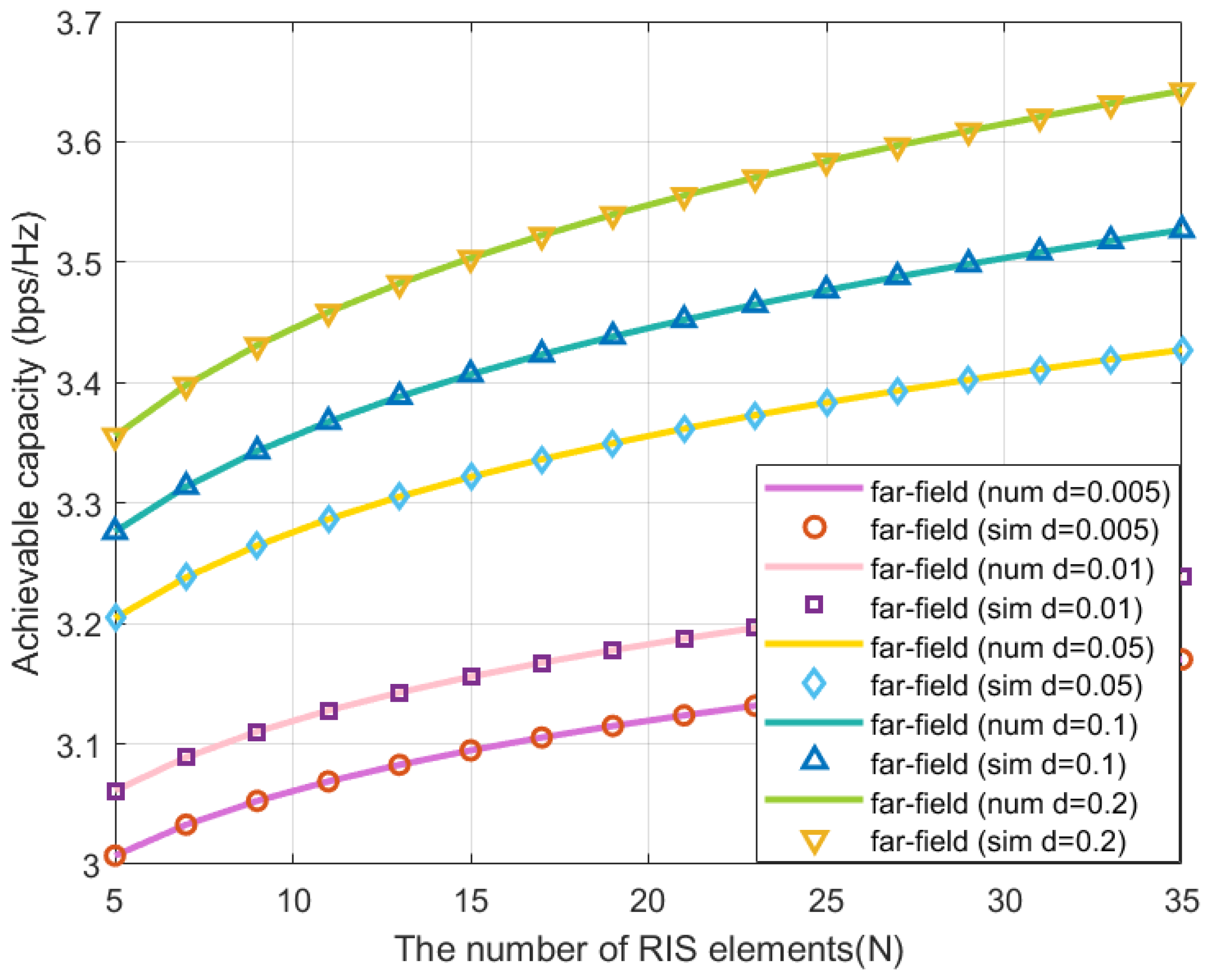
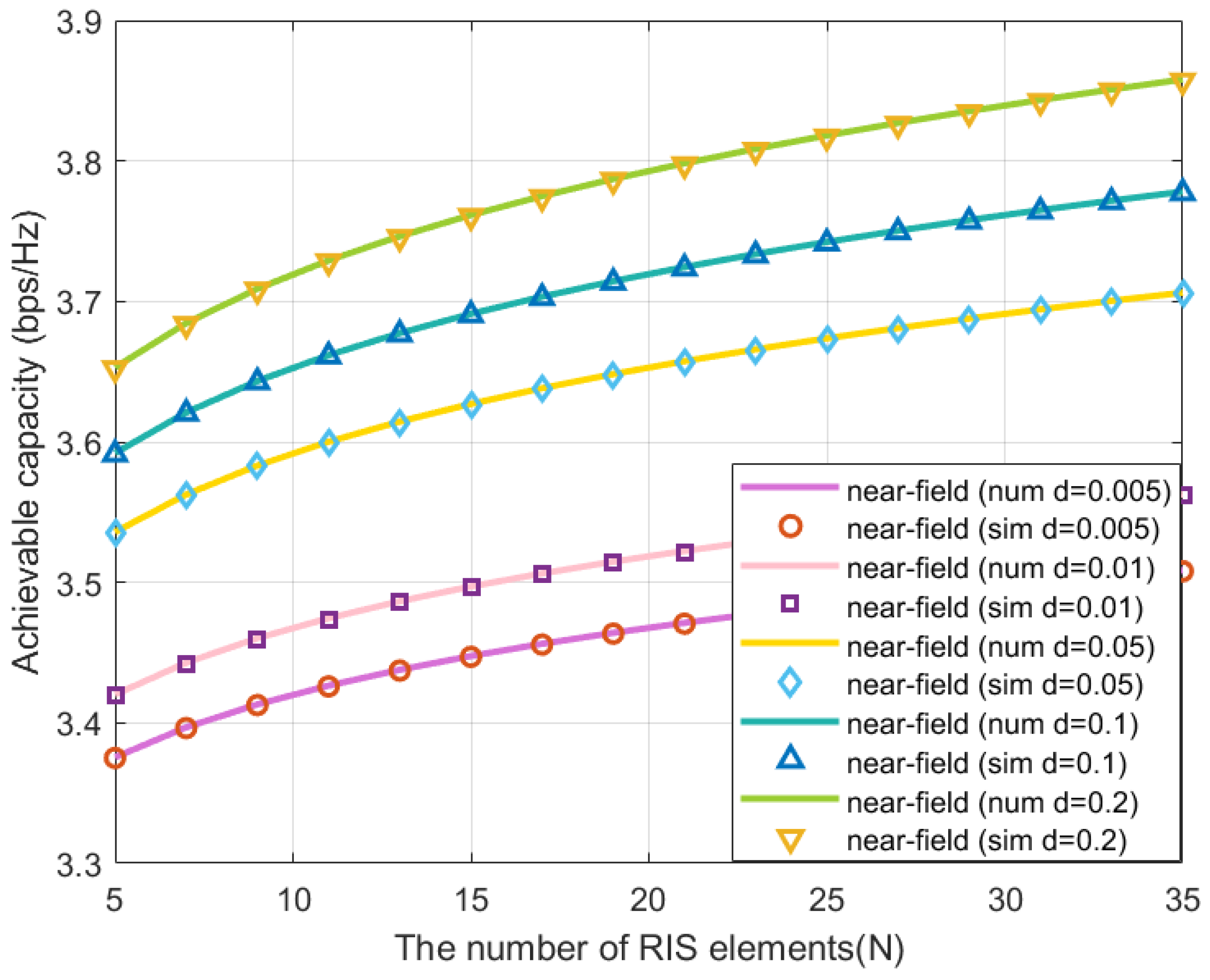
Figure 2 and Figure 3 illustrate the results of the achievable capacity with the increasing quantity of RIS elements in lower frequency band and mmwave band, respectively. It is observed that the theoretical upper bound for the achievable capacity aligns well with the simulated values, confirming the accuracy and validity of our derived results. As the increase of RIS reflecting elements quantity, the maximum value of the achievable capacity remarkablely improves. In addition, extending the length of the RIS elements leads to a notable enhancement in the upper bound of the capacity, and this trend is consistent across both lower frequency bands and the mmWave band.
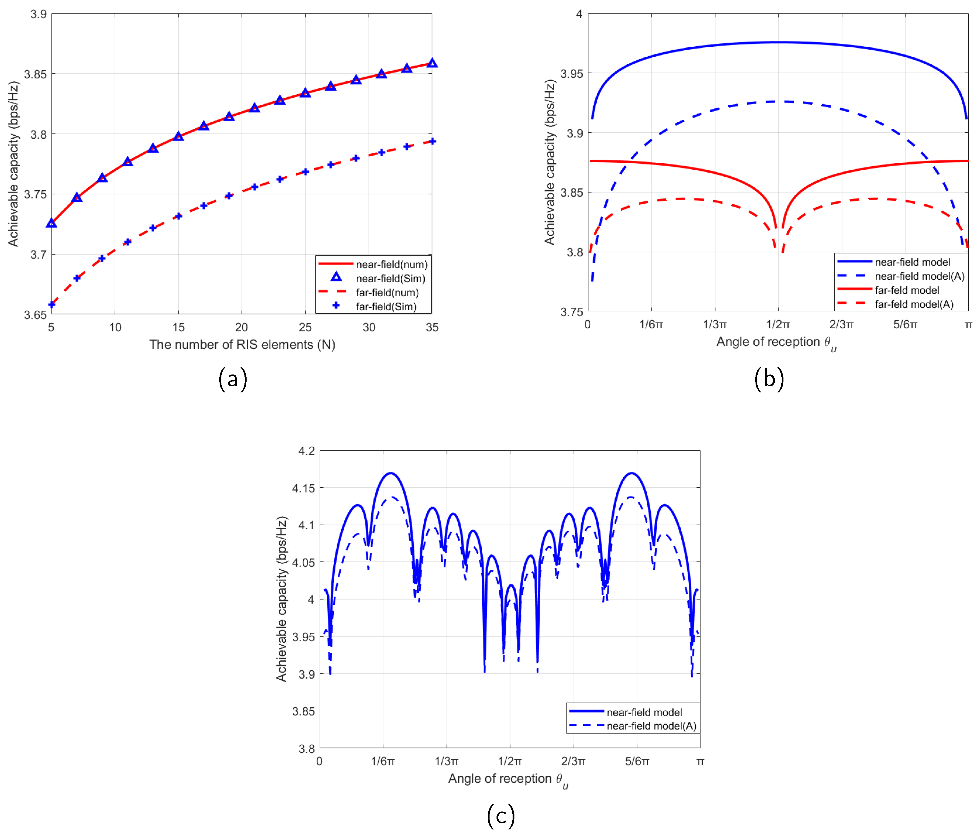
Figure 4(a) shows that achievable capacity improves with the increase of reflecting element quantity of RIS in far field, but the performance is not as good as in near field. Figure 4(b) shows the upper bound of the achievable capacity for lower frequency band and mmwave band versus angle θ u , where θ u = π 6 , φ b = π 3 , φ u = π 6 and N = 25 . We can observe that the upper bound of achievable capacity depends significantly on both directions of BS and User.In near field, when θ u approaches 0 or π , both the projection aperture of the RIS and sin θ u are reduced, leading to a smaller result. Conversely, when θ u approaches π 2 , the projection aperture of the RIS increases, resulting in a higher achievable capacity. However, in far field, when θ u approaches π 2 , the achievable capacity decreases due to the reduced power radiation pattern. The achievable capacity without considering the projected aperture is higher than the situation where the projected aperture is considered, which reflects that projection aperture has an influence on the upper bound of the achievable capacity. Figure 4(c) illustrates the achievable capacity as a function of θ u by setting α n , m as a specific value. We can obtain higher achievable capacity by adjusting θ u as θ u = 35 . It is observed that the achievable capacity without considering the projected aperture in near field is higher, which is consistent with the conclusion in Figure 4(b).
Figure 2. Achievable capacity versus RIS elements number N in far field.
Preprints 137678 g002
Figure 3. Achievable capacity versus RIS elements number N in near field.
Preprints 137678 g003
Figure 4. (a) Achievable capacity versus RIS elements number N in the near and far field regions. (b) Achievable capacity versus θ u with θ b = π 6 , φ b = π 3 , φ u = π 6 in the near and far field regions. (c) Near field region
Preprints 137678 g004

5. Conclusion

The RIS-assisted wireless communications path loss modeling channel in near and far field have been investigated in this paper. The expressions for the upper bound of achievable capacity in two different scenarios have been derived, respectively. The simulation results have shown that the increasing RIS elements number or the RIS elements length will significantly improve system performance. Simultaneously, both the elevation and the azimuth angles of signals transmitted from RIS to user and the projection aperture have impacts on achievable capacity, which are confirmed in this paper. These findings can enhance the flexibility of RIS deployment and offer more insights for future design of practical RIS-assisted communication systems.

References

  1. Mu, X.; Xu, J.; Liu, Y.; Hanzo, L. Reconfigurable Intelligent Surface-Aided Near-Field Communications for 6G: Opportunities and Challenges. IEEE Veh. Technol. Mag. 2024, 19, 65–74. [CrossRef]
  2. Ha, D.-H.; Duy, T.T.; Son, P.N.; Le-Tien, T.; Voznak, M. Security-reliability trade-off analysis for rateless codes-based relaying protocols using NOMA, cooperative jamming and partial relay selection. IEEE Access 2021, 9, 131087–131108. [CrossRef]
  3. Huang, J; et al. Reconfigurable Intelligent Surfaces: Channel Characterization and Modeling. Proceedings of the IEEE 2022, 110, 1290–1311. [CrossRef]
  4. Cheng, Y.; Huang, C.; Peng, W.; Debbah, M.; Hanzo, L.; Yuen, C. Achievable Rate Optimization of the RIS-Aided Near-Field Wideband Uplink. IEEE Trans. Wireless Commun. 2024, 23, 2296–2311. [CrossRef]
  5. Tian, J.; Han, Y.; Jin, S.; Li, X.; Zhang, J.; Matthaiou, M. Near-Field Channel Reconstruction in Sensing RIS-Assisted Wireless Communication Systems. IEEE Trans. Wireless Commun. 2024, to appera.
  6. Bian, M.; Shi, Y.; Huang, Y.; Tang, X.-W. QoS-aware energy storage maximization in the RIS-aided joint-SWIPT-MEC System. IEEE Commun. Lett. 2023, 27, 3434–3438. [CrossRef]
  7. Ghadi, F.R.; López-Martínez, F.J. RIS-Aided Communications Over Dirty MAC: Capacity Region and Outage Probability. IEEE Commun. Lett. 2023, 27, 2009–2013. [CrossRef]
  8. Wang, Y.; Zhang, Y.; Ren, Y.; Pang, L.; Chen, Y.; Li, J.; Joint BS-RIS-User Association and Deployment Design for Multi-RIS-Aided Wireless Networks. IEEE Commun. Lett. 2024, 28, 2181–2185. [CrossRef]
  9. Demir, Ö. T.; Björnson, E. Wideband Channel Capacity Maximization With Beyond Diagonal RIS Reflection Matrices. IEEE Wireless Commun. Lett. 2024, to appera.
  10. Liu, Y.; Wang, Z.; Xu,J.; Ouyang, C.; Mu, X.; Schober, R. Near-Field Communications: A Tutorial Review. IEEE Open Journal of the Communications Society 2023, 4, 1999–2049. [CrossRef]
  11. Jin, Y.; Qi, H. Near-Field Channel Estimation for RIS Assisted 6G Wireless Communication. 2023 IEEE International Conference on Signal Processing, Communications and Computing (ICSPCC) 2023, 1–6.
  12. Zhang, X.;Zhang, H. Hybrid Reconfigurable Intelligent Surfaces-Assisted Near-Field Localization. IEEE Commun. Lett. 2023, 27, 135–139. [CrossRef]
  13. Lv, S.; Liu, Y.; Xu, X.; Nallanathan, A.; Swindlehurst, A.L. RIS-Aided Near-Field MIMO Communications: Codebook and Beam Training Design. IEEE Trans. Wireless Commun. 2024, 23, 12531–12546. [CrossRef]
  14. Xu, J.; Mu, X.; Liu, Y. Exploiting STAR-RISs in Near-Field Communications. IEEE Trans. Wireless Commun. 2024, 23, 2181–2181. [CrossRef]
  15. Emenonye, D.-R.; Dhillon, H.S.; Buehrer, R.M. RIS-Aided Localization Under Position and Orientation Offsets in the Near and Far Field. IEEE Trans. Wireless Commun. 2023, 22, 9327–9345. [CrossRef]
  16. Yang, S.; Lyu, W.; Hu, Z.; Zhang, Z.; Yuen, C. Channel Estimation for Near-Field XL-RIS-Aided mmWave Hybrid Beamforming Architectures. IEEE Trans. Veh. Technol. 2023, 72, 11029–11034. [CrossRef]
  17. Zhang, X.; Wang, Z.; Zhang, H.; Yang, L. Near-Field Channel Estimation for Extremely Large-Scale Array Communications: A Model-Based Deep Learning Approach. IEEE Commun. Lett. 2023, 27, 1155–1159. [CrossRef]
  18. Gan, X.; Huang, C.; Yang, Z.; Zhong, C.; Zhang, Z.; Near-Field Localization for Holographic RIS Assisted mmWave Systems. IEEE Commun. Lett. 2023, 27, 140–144. [CrossRef]
  19. Tang, W.; et al. Wireless Communications with Reconfigurable Intelligent Surface: Path Loss Modeling and Experimental Measurement. IEEE Trans. Wireless Commun. 2021, 20, 421–439. [CrossRef]
  20. Gradshteyn, I.S.; Ryzhik, I.M. Table of Integrals, Series, and Products. New York, NY, USA: Academic 2007, 7.
Disclaimer/Publisher’s Note: The statements, opinions and data contained in all publications are solely those of the individual author(s) and contributor(s) and not of MDPI and/or the editor(s). MDPI and/or the editor(s) disclaim responsibility for any injury to people or property resulting from any ideas, methods, instructions or products referred to in the content.
Copyright: This open access article is published under a Creative Commons CC BY 4.0 license, which permit the free download, distribution, and reuse, provided that the author and preprint are cited in any reuse.
Prerpints.org logo

Preprints.org is a free preprint server supported by MDPI in Basel, Switzerland.

Subscribe

© 2024 MDPI (Basel, Switzerland) unless otherwise stated