1. Introduction
The F1 in Schools™ Competition is a distinguished STEM initiative that immerses students in the design and engineering of miniature race cars under strict guidelines. This program provides a robust platform for the practical application of STEM principles, emphasizing the integration of theoretical knowledge with hands-on engineering practice [
1]. This study tackles the challenge of minimizing drag and controlling turbulent airflow.
Designing a miniature race car requires a deep understanding of aerodynamic principles and engineering methods. Achieving optimal performance involves the strategic application of AutoCAD for precise component modeling and Computational Fluid Dynamics (CFD) for in-depth aerodynamic analysis. AutoCAD facilitates the detailed design of critical components such as the front wing, car body, and sidepods, which play a pivotal role in minimizing drag and enhancing speed. CFD simulations are employed to analyze airflow patterns and drag forces, providing essential data for refining aerodynamic efficiency [
2].
This approach enhances the understanding of engineering principles within the STEM framework. Aerodynamics play a critical role in racing: drag limits the speed, while downforce improves the tire traction [
3]. Autodesk Inventor Professional is used for car design modeling and virtual testing, improving aerodynamic performance before physical prototyping. Dharmawan et al. (2020) conducted a study focusing on the aerodynamic effects of a rear wing, specifically utilizing the Eppler 423 airfoil at varying angles of attack. Their findings revealed that an angle of attack of 12° yielded optimal aerodynamic coefficients, demonstrating the significant role that aerodynamic modifications play in improving cornering performance and reducing slip at high velocities [
4].
Aerodynamic drag forces affecting fuel consumption emphasized the importance of reducing drag, particularly at the rear end of the vehicle. Prabhu et al. (2020) [
5] employing various spoiler designs analyzed through CFD simulations in SOLIDWORKS, they demonstrated that effective aerodynamic modifications could lead to substantial improvements.
By linking theoretical knowledge with practical applications, such research not only advances vehicle design but also promotes STEM education. It offers valuable insights for future developments in automotive aerodynamics [
6,
7]. This paper presents a comprehensive overview of the design process, simulation results, and the engineering principles applied to develop a high-performance miniature race car. The outcomes demonstrate the importance of aerodynamics in racing performance and the methodologies used to achieve a better design, offering a unique perspective due to the lack of content focused on these specific optimizations.
2. Methodology
Our primary objective is to design and construct a race car optimized for peak performance on a straight track. The focus of this project is on maximizing speed, reducing drag where drag force is
here,
is Drag Force,
is Air Density,
is Relative Velocity,
is Drag Coefficient and A is Cross-Sectional Area.
To ensure the car's stability and reliability. Using advanced computer-aided design (CAD) and computer-aided manufacturing (CAM) software, we precisely modeled every component of the car, including the front wing, rear wing, and sidepods. Additionally, computational analysis was conducted to simulate the car’s performance prior to manufacturing, allowing for early identification and rectification of potential design issues. Through iterative brainstorming and testing, we ensure the final design achieves maximum speed while maintaining durability and efficiency over multiple races. The design and construction process was broken into stages: first, we focused on the car body, followed by the front wing, and lastly, the rear wing, which plays a crucial role in managing airflow across the vehicle.
Figure 1.
Flowchart for Car Design.
Figure 1.
Flowchart for Car Design.
2.1. Car Body
Cars with smoother airflow around them tend to exhibit better aerodynamic performance compared to those relying solely on sharp, pointy shapes. While a pointed front may help reduce drag to some extent, the critical factor in optimizing aerodynamics is how well the air flows around the entire car. For instance, even with a pointed front, significant drag can still occur if the airflow around the rest of the body becomes turbulent.
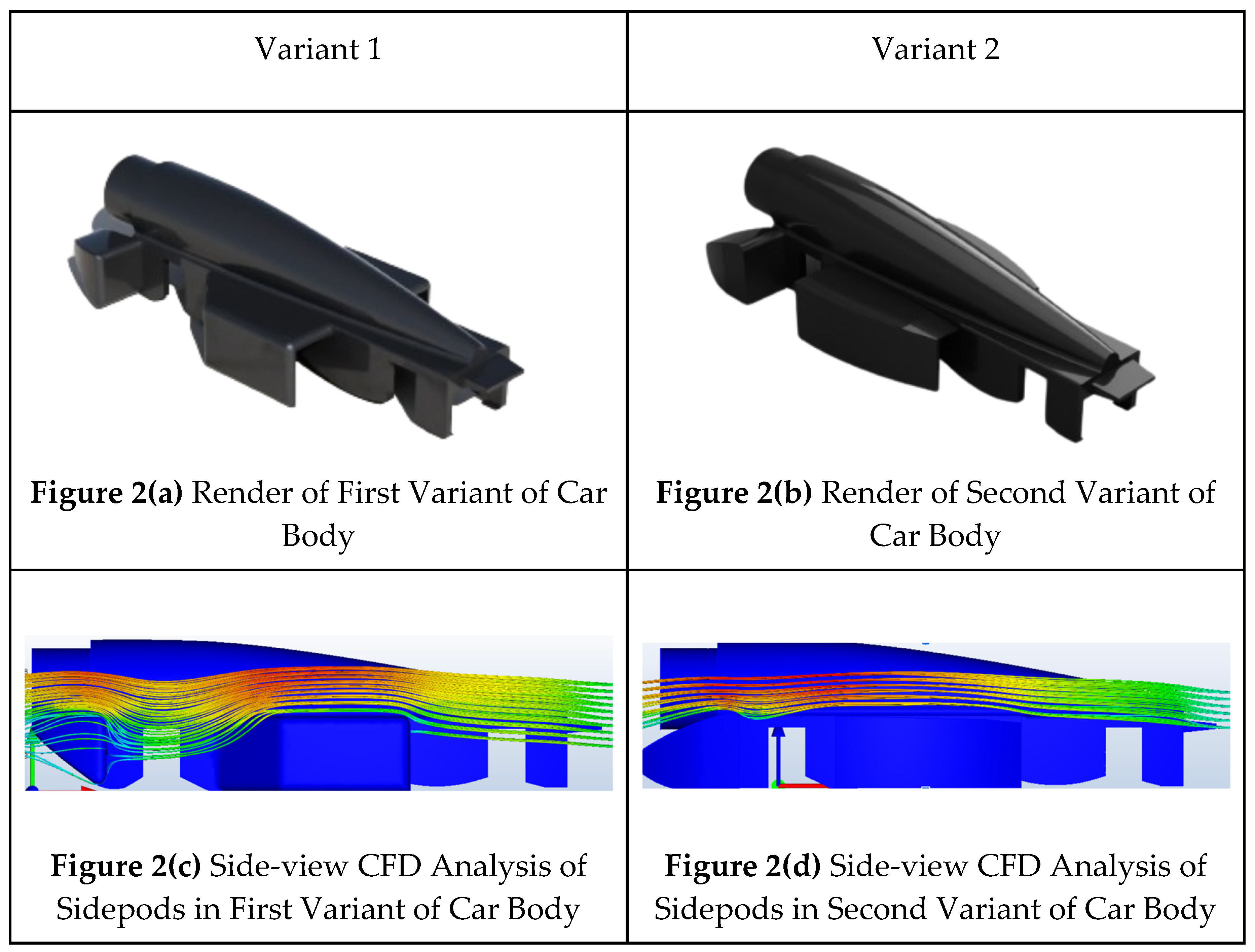
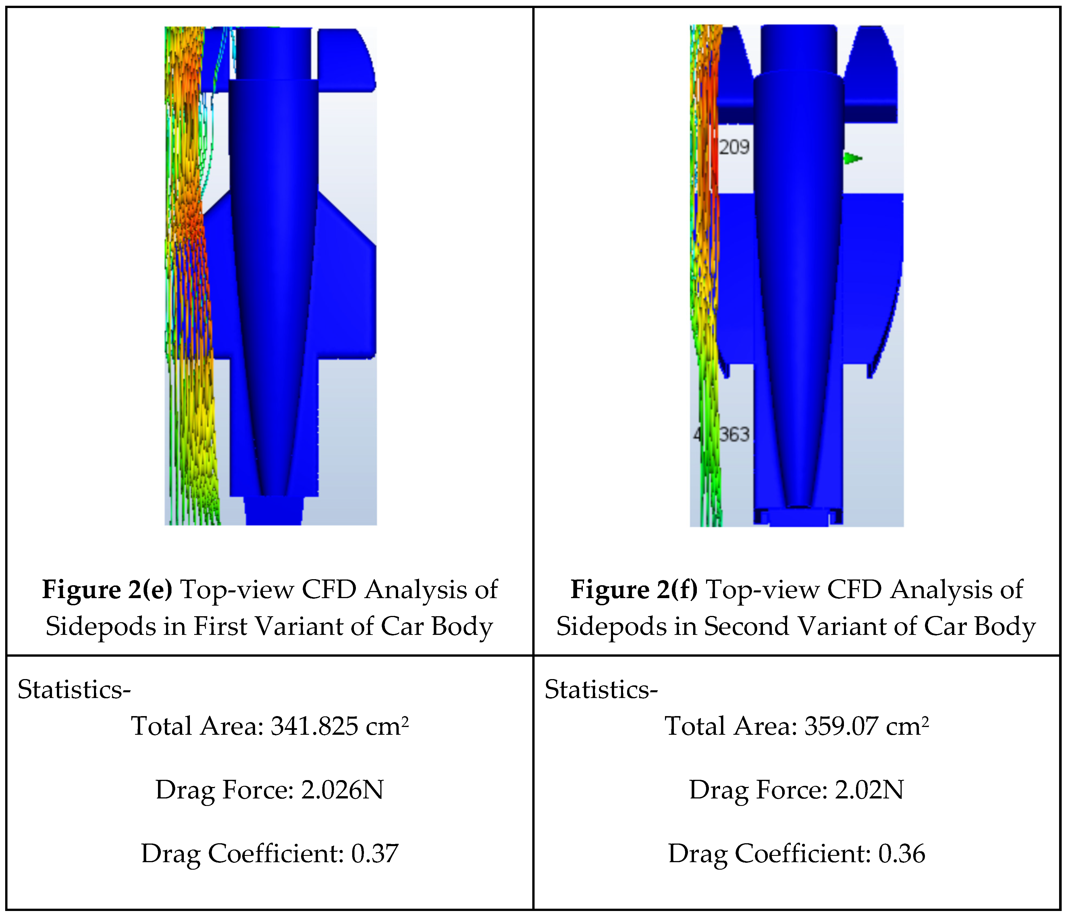
In this study, two car body designs with nearly identical statistics on paper were analyzed. The main differentiating factor was how each design managed airflow. Even minor differences in how air interacts with the car’s surface can have a substantial impact on overall aerodynamic performance.
The key distinction between these two car bodies lies in their approach to managing airflow. The first design efficiently redirects air over its surface, promoting streamlined and smooth airflow. This minimizes turbulence and enhances aerodynamic performance by ensuring that air flows smoothly over and around the vehicle. In contrast, the second car body experiences more turbulent airflow due to less effective management, resulting in increased drag and reduced aerodynamic efficiency. It is essential to consider the entire vehicle design rather than focusing on individual parts in isolation, as components such as sidepods, rear sidepods, and the central body edges can have a significant effect on overall performance.
After adding the necessary components to the car bodies, such as the front and rear wings, Computational Fluid Dynamics (CFD) analysis was conducted. The results revealed a 33% reduction in the drag coefficient. This improvement can be attributed to optimizing the airflow around the vehicle, thereby reducing turbulence and increasing aerodynamic efficiency. Hence, the second body design was selected for the final model.
2.2. Front Wing
In Formula 1 racing, tire wake refers to the turbulent airflow generated by exposed tires [
8]. This chaotic airflow increases drag and reduces aerodynamic efficiency, negatively impacting critical components such as the rear wing and sidepods, which are essential for maintaining downforce and stability. To address tire wake, we divided the problem into two regions: the upper and lower halves of the tire. Four variants of the front wing design were tested to determine their effectiveness in managing tire wake.
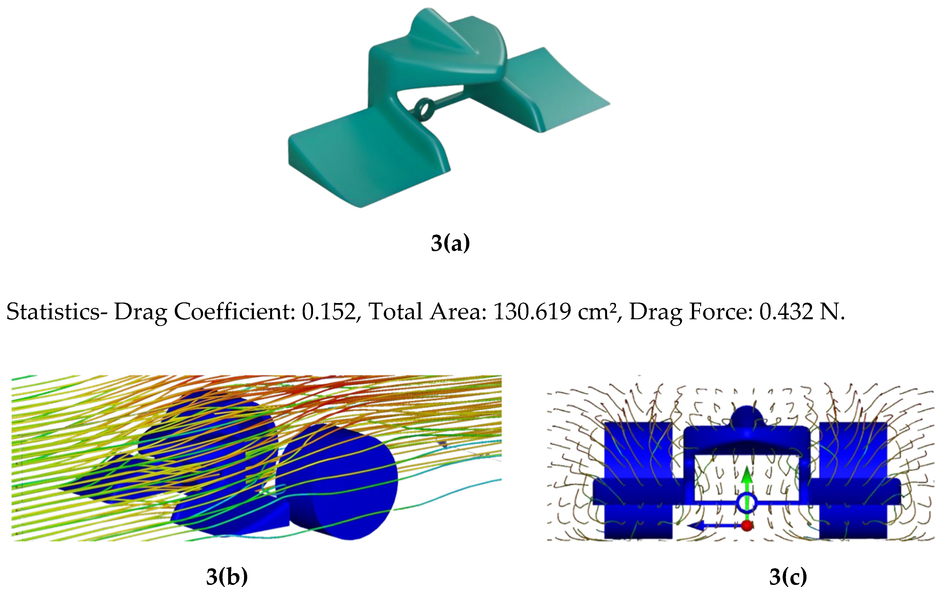
2.2.1. First Variant
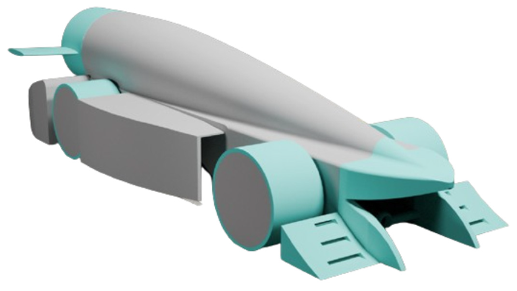
Despite its compact and streamlined design, this variant did not effectively direct airflow away from the upper tire, resulting in increased drag and slightly reduced aerodynamic efficiency.
Figure 3.
(a) Render of First Variant, (b) Isometric-view CFD Render of First Variant (c) Front-view CFD Render of First Variant.
Figure 3.
(a) Render of First Variant, (b) Isometric-view CFD Render of First Variant (c) Front-view CFD Render of First Variant.
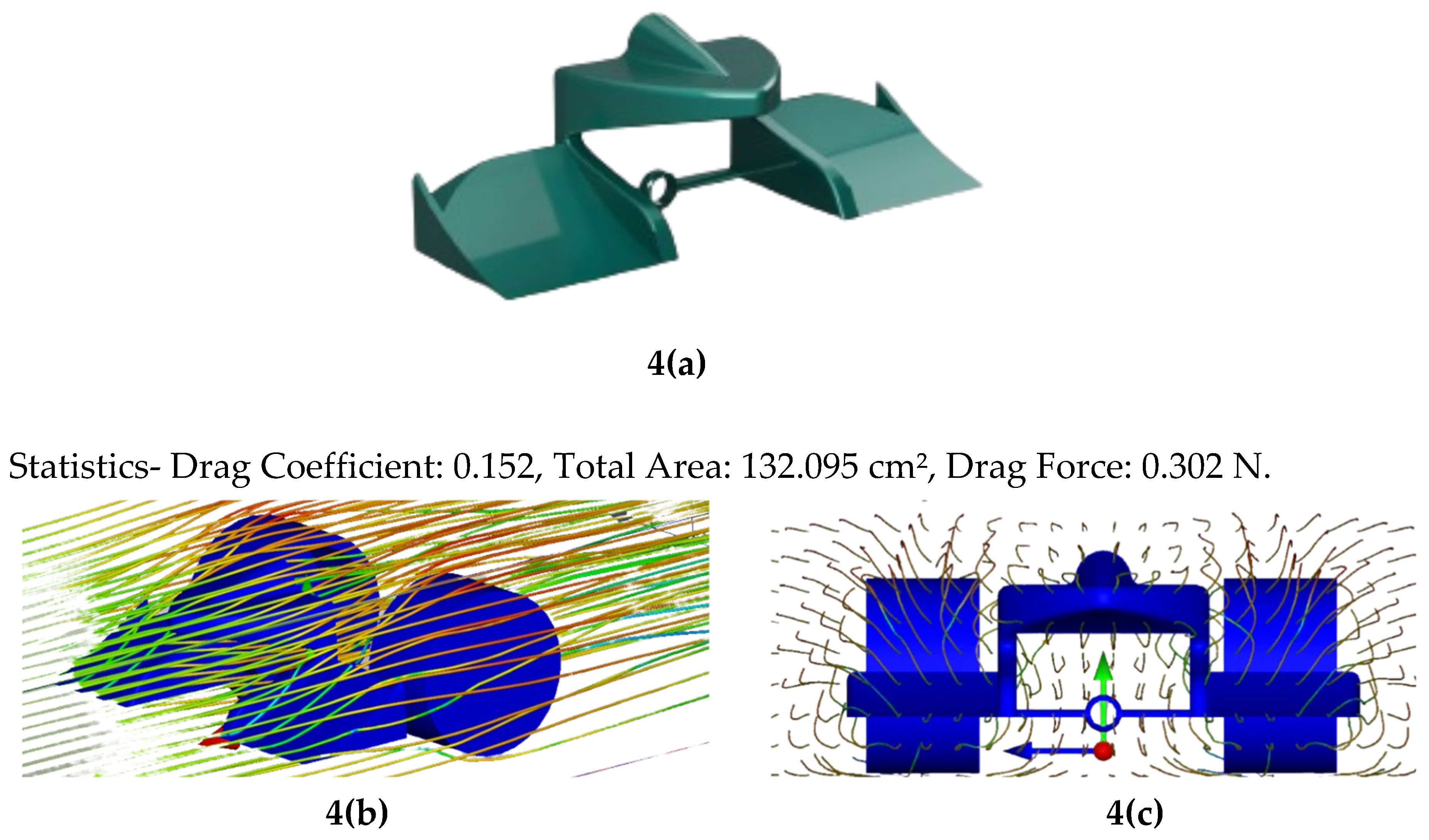
2.2.2. Second Variant
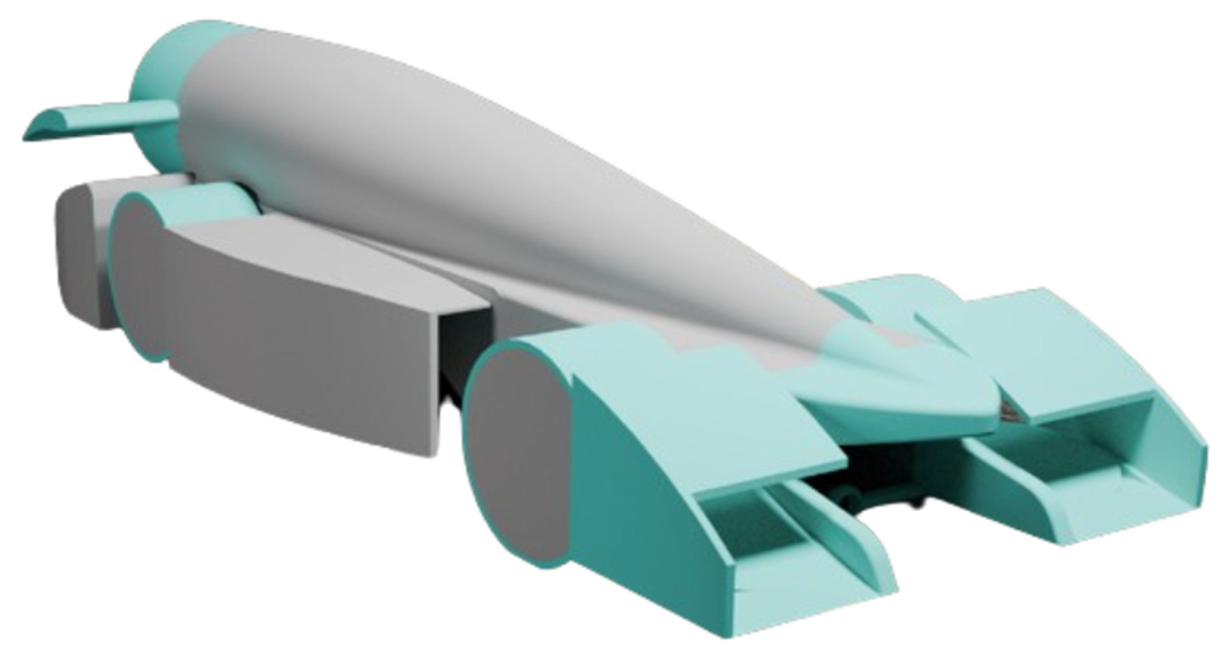
Incorporating an outwash effect, inspired by the Y250 vortex, this variant successfully redirected airflow away from the tires. However, drag persisted as airflow continued to impact the upper tire.
Figure 4.
(a) Render of Second Variant, (b) Isometric-view CFD Render of Second Variant (c) Front-view CFD Render of Second Variant.
Figure 4.
(a) Render of Second Variant, (b) Isometric-view CFD Render of Second Variant (c) Front-view CFD Render of Second Variant.
2.2.3. Third Variant
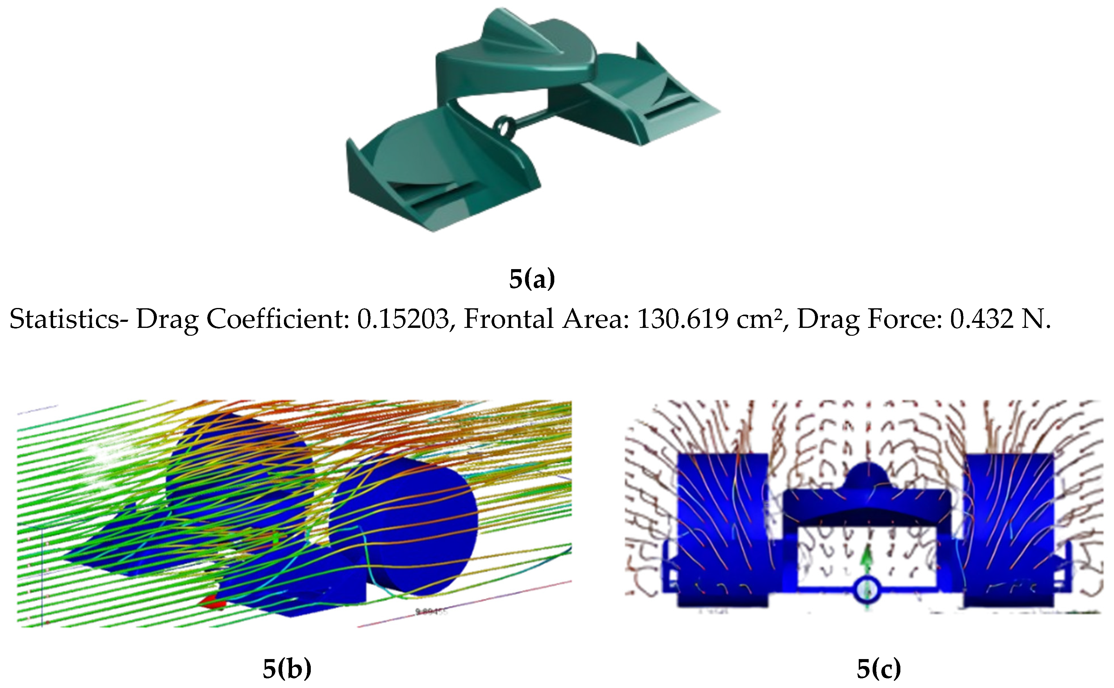
To maximize the outwash effect, slits were introduced, which showed a modest improvement in airflow management, but the overall drag coefficient remained unchanged.
Figure 5.
(a) Render of Third Variant, (b) Isometric-view CFD Render of Third Variant (c) Front-view CFD Render of Third Variant.
Figure 5.
(a) Render of Third Variant, (b) Isometric-view CFD Render of Third Variant (c) Front-view CFD Render of Third Variant.
2.2.4. Fourth Variant
In an attempt to address the upper tire airflow issue, wing covers were added. While this design was highly effective in protecting the tires and enhancing aerodynamic efficiency, it was ultimately disqualified for violating competition regulations.
Figure 6.
(a) Render of Second Variant, (b) Isometric-view CFD Render of Second Variant (c) Front-view CFD Render of Second Variant.
Figure 6.
(a) Render of Second Variant, (b) Isometric-view CFD Render of Second Variant (c) Front-view CFD Render of Second Variant.
2.3. Rear Wing
After developing a low-drag wing, the next step involved determining its optimal orientation—whether a front-swept or back-swept configuration would be more suitable.
2.3.1. Front-Swept Wings
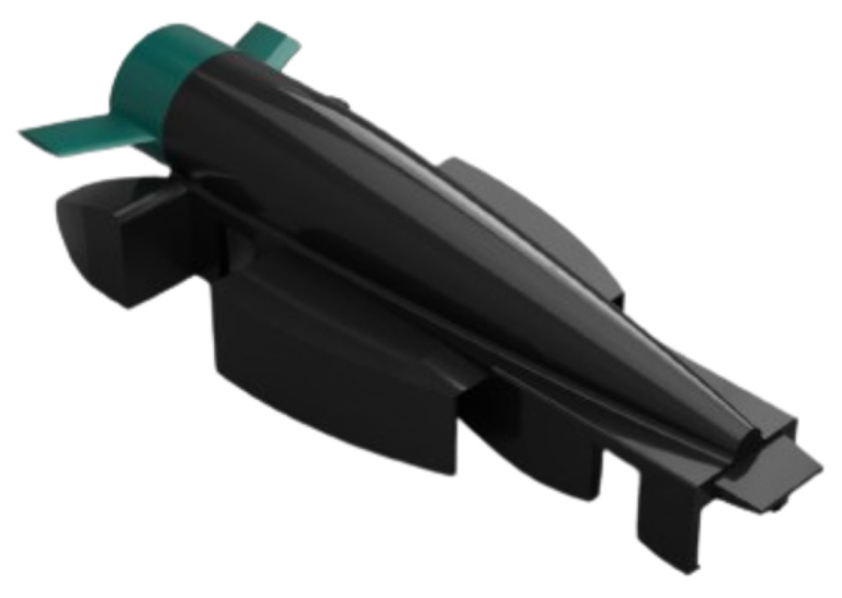
These wings naturally direct airflow inward toward the car body, which reduces vortex drag and improves lift. It was hypothesized that this inward airflow could assist in concentrating thrust, potentially enhancing overall performance. However, front-swept wings are also prone to generating higher levels of drag at increased speeds due to the larger surface area exposed to airflow disturbances. While the increased lift might offer some advantages, this comes at the cost of aerodynamic efficiency, particularly at higher velocities.
Figure 7.
Isometric-view of Front-Swept Car Variation.
Figure 7.
Isometric-view of Front-Swept Car Variation.
2.3.2. Back-Swept Wings
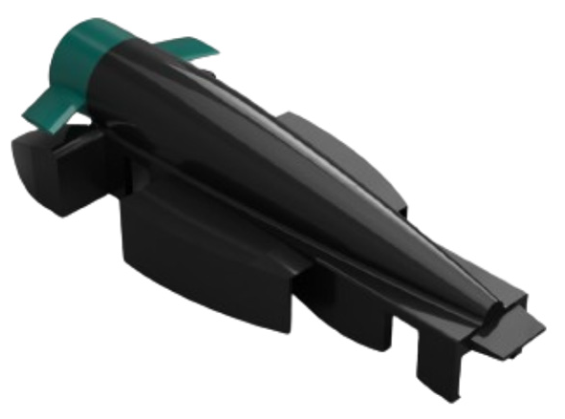
In contrast, back-swept wings are more aerodynamically efficient, minimizing drag and improving the vehicle's speed potential. However, because they direct airflow away from the body, these wings may not contribute significantly to increasing thrust, an aspect that could potentially affect acceleration.
Figure 8.
Isometric-view of Back-Swept Car Variation.
Figure 8.
Isometric-view of Back-Swept Car Variation.
According to CFD analysis, the front-swept wing showed approximately 10% more drag compared to the back-swept wing. But to evaluate whether the increased "boost" in lift could overpower the additional drag, further on-track testing was necessary. Ultimately, the back-swept wing demonstrated better overall performance during track trials, producing faster times, and was thus selected as the final design choice.
2.4. Car Variants
By experimenting with changes in the car body, rear wing, front wing, and airflow management, each variant helped identify and evaluate the most efficient configuration.
2.4.1. May
This car, inspired by the Batmobile from Batman Forever (1995), features an aerodynamic upper body designed to minimise drag. The focus was on achieving minimal drag.
Figure 9.
Isometric View of May Variant.
Figure 9.
Isometric View of May Variant.
The car faced significant issues with turbulent air along the sides. The front wing couldn’t manage the tyre wake effectively, leading to poor airflow around the car. While the central section had clean airflow and earned us the regional fastest car title in 2022, the side turbulence reduced overall aerodynamic efficiency, requiring further improvements.
Statistics- Total Area: 597.688 cm2, Drag Force: 2.753N, Drag Coefficient: 0.3
2.4.2. Jeremy
This car, inspired by Ferrari's 2022 F1-75, aimed to address issues with turbulent air along the sides. The design focused on improving airflow around the vehicle.
Figure 10.
Isometric View of Jeremy Variant.
Figure 10.
Isometric View of Jeremy Variant.
The car significantly reduced drag, thanks to its curved side pod design, which generated an outwash effect and provided cleaner airflow. The front wing, featuring a reverse Y250 vortex concept, further reduced tyre wake and improved overall aerodynamic efficiency.
Statistics- Total Area: 599.968 cm2,Drag Force: 2.632N, Drag Coefficient: 0.28
2.4.3. Hammond
In this car, we tested slits on the front wing to better manage airflow and reduce turbulence. We also modified and adjusted the curvature of the rear sidepods to further optimise the outwash effect and improve aerodynamic efficiency.
Figure 11.
Isometric View of Hammond Variant.
Figure 11.
Isometric View of Hammond Variant.
The refined curvature of the sidepods led to reduced drag and enhanced overall performance. Fine-tuning these elements improved outwash and provided cleaner airflow along the car's body. Additionally, this process helped us determine the optimal placement and dimensions for slits on the reverse Y250 vortex wing.
Statistics- Total Area: 607.567 cm2, Drag Force: 2.476N, Drag Coefficient: 0.26
2.4.4. Stig
This design drew inspiration from the Season 3 Formula E- cars. After addressing the lower tire wake, we turned our focus to improving the aerodynamics of the upper half of the tyre which was disrupting airflow over the sidepods. This involved creating multiple iterations of the rear side pods to further enhance airflow.
Figure 12.
Isometric View of Stig Variant.
Figure 12.
Isometric View of Stig Variant.
This design violated regulations due to wing structures extending more than 15mm above the tire. Despite this, it significantly influenced our final design and met key goals, offering valuable insights. We used its strengths to create a revised version that complied with regulations while maintaining performance
Statistics- Total Area: 597.688 cm2, Drag Force: 2.753N, Drag Coefficient: 0.3
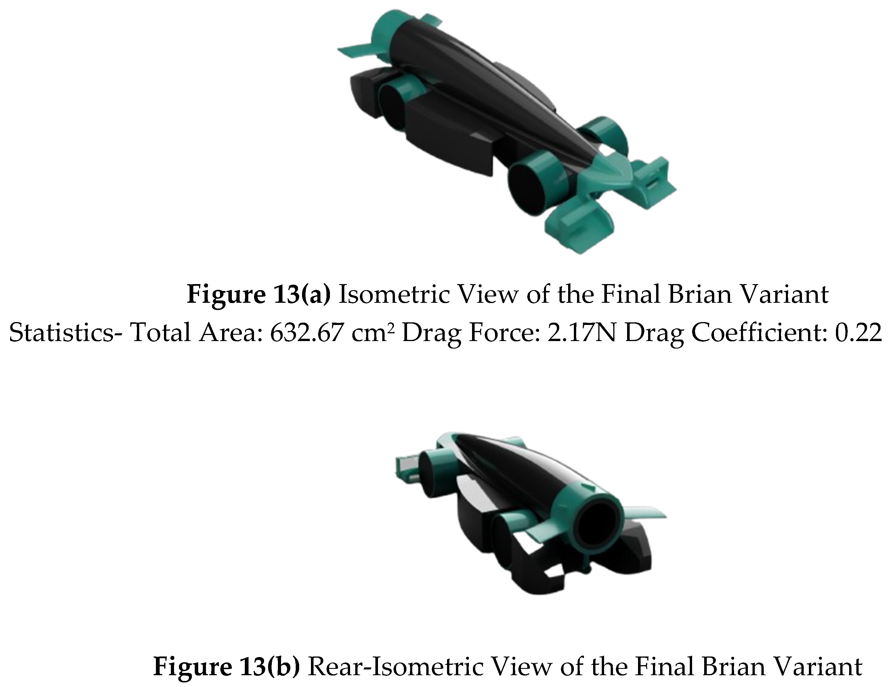
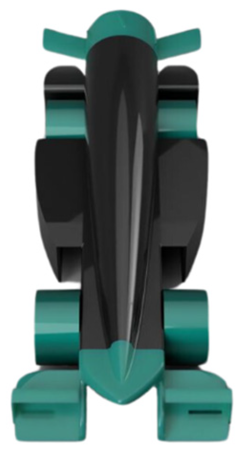
2.4.5. Brian
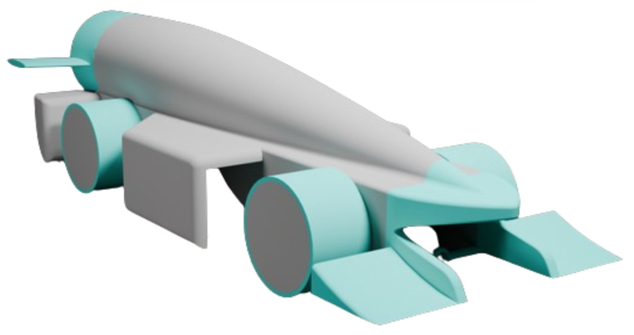
After extensive refinement across various iterations, we arrived at an optimized design capable of delivering race-winning performance.
3. Result & Discussion
The final iteration of our F1 in Schools™ car represents the culmination of countless hours of design, testing, and refinement. Our design philosophy centres around achieving cleaner airflow around the car, as we believe this is more effective for optimising aerodynamics than simply relying on individual pointy, aerodynamic components. While a pointy front can help reduce drag, the overall efficiency hinges on how smoothly air flows around the entire vehicle. A car with a sharp front but turbulent airflow along its body still encounters significant drag. Thus, our design prioritizes a cleaner flow of air around the car rather than just an individual component being aerodynamic.
3.1. Car Body
The car body is crafted to efficiently redirect air and optimise airflow across its surface, resulting in a smooth airflow. This design minimises turbulent air and compliments other components.
Figure 14.
Rear-Isometric View of the Final Car.
Figure 14.
Rear-Isometric View of the Final Car.
3.2. Front Wing
To address the issue of tire wake, we finally introduced a specially designed front wing that effectively redirects airflow around the tires. The upper element is highly effective, deflecting a substantial amount of air away from the upper half of the tire. Due to its thin and lightweight design, the upper element also flexes mid-race, rising beyond the 15mm regulation mark in response to aerodynamic forces, which helps further reduce upper tire wake. This design feature enables it to pass both pre-race and post-race inspections while significantly improving airflow management. The lower element generates an outwash effect, and, combined with the sidepods, directs air away from the car body, enhancing overall aerodynamic efficiency.
Figure 15.
Isometric View of the Final Front Wing.
Figure 15.
Isometric View of the Final Front Wing.
3.3. Rear Wing
A low-drag backward-swept rear wing that generates considerably less drag compared to a forward-swept design.
Figure 16.
Isometric View of the Final Rear Wing.
Figure 16.
Isometric View of the Final Rear Wing.
4. Conclusion
In conclusion, this study optimized a race car for straight-track performance by focusing on aerodynamic efficiency across multiple design iterations. Using CFD simulations, we compared four car variants, each with adjustments to the car body, front wing, and rear wing.
The first variant, had a drag coefficient of 0.3 and a drag force of 2.753N, but faced significant side turbulence. The second variant, inspired by Ferrari’s F1-75, reduced drag to 2.632N and improved airflow with its reverse Y250 vortex concept. The third variant further optimized outwash with slits in the front wing, achieving the lowest drag force at 2.476N. The fourth variant violated regulations but provided crucial insights for optimizing the final design.
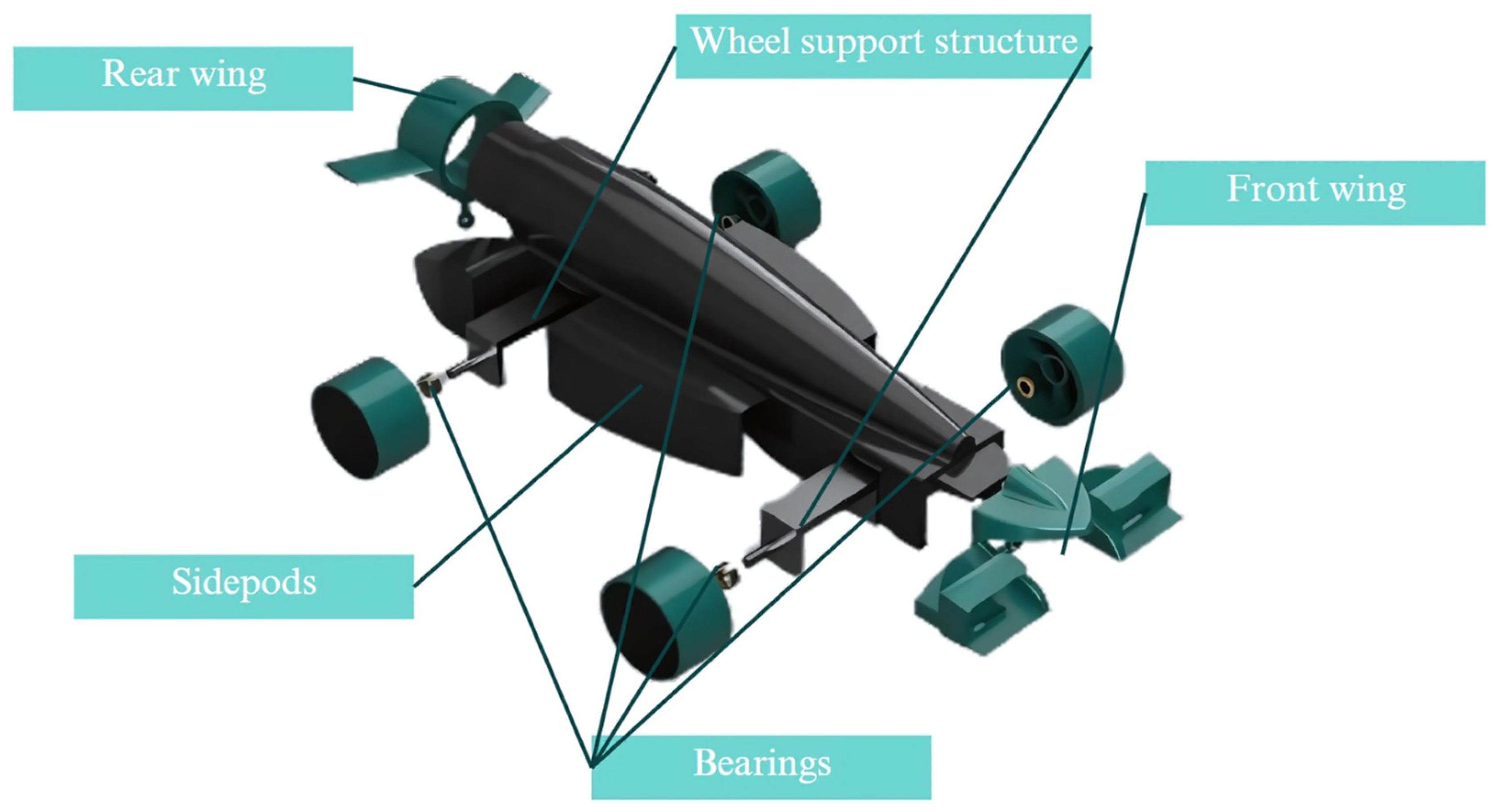
Figure 17.
Labelled View of the Final Car (Brian) with all Components.
Figure 17.
Labelled View of the Final Car (Brian) with all Components.
This study highlights the critical role of aerodynamic optimization in race car design, setting the foundation for future advancements in competitive racing performance. The following graphs contain a comparative study of the drag coefficients and drag force of all the variants
Figure 18.
(a) Comparative Study of Drag Forces of All Car Variants, (b) Comparative Study of Drag Coefficient of All Car Variants.
Figure 18.
(a) Comparative Study of Drag Forces of All Car Variants, (b) Comparative Study of Drag Coefficient of All Car Variants.
The engineering drawings offered clear visuals of the car's design, allowing for accurate component measurements and helping pinpoint areas for aerodynamic adjustments. These sketches played a key role in refining the structure before running simulations.
Figure 19.
Engineering Drawings of the Final Car Variant (unit in mm).
Figure 19.
Engineering Drawings of the Final Car Variant (unit in mm).
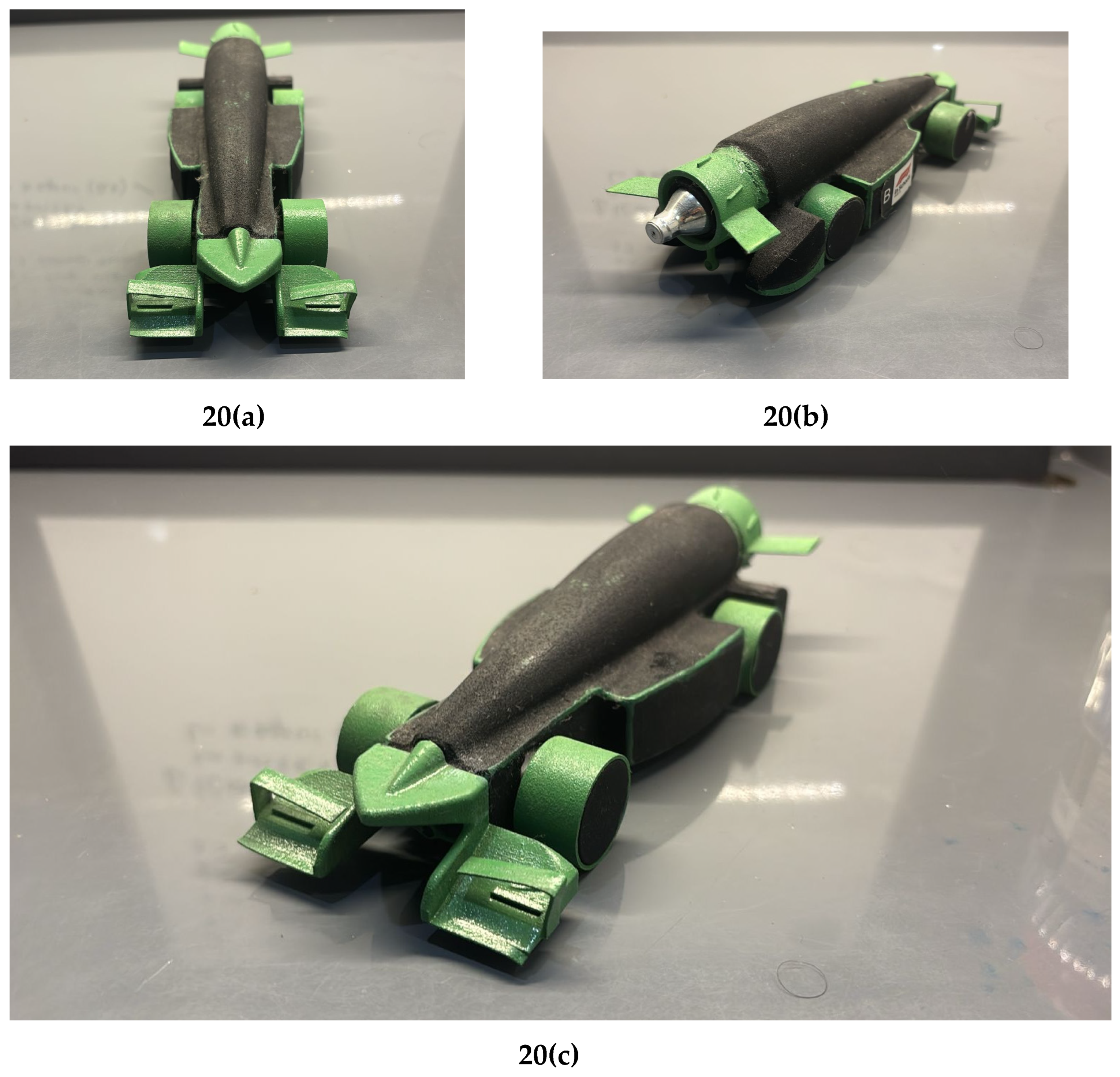
Below are images of the final manufactured car, painted along with the program sticker on the side and the canister at the back.
Figure 20.
(a) Front View of Manufactured Car, (b) Isometric Back View of Manufactured Car along with Program Sticker and Canister (c) Isometric Side View of Manufactured Car.
Figure 20.
(a) Front View of Manufactured Car, (b) Isometric Back View of Manufactured Car along with Program Sticker and Canister (c) Isometric Side View of Manufactured Car.
Acknowledgements
We express our deep gratitude to F1 in Schools™ for providing an exceptional platform to explore engineering and technical skill development. We also extend our appreciation to STEMplify for their invaluable support, with special thanks to our mentor, Shubham Taneja, for his guidance throughout the project. Our sincere thanks go to Amity International School Saket for their ongoing encouragement, particularly to our mentor, Richa Pandey Ma'am, for her dedicated support. Finally, we recognize the contributions of our teammates, Diya Arora, Aashman Madan, and Devraj Sehrawat, whose collaboration was crucial to the project's success.
References
- Warren FS, Myers M, & Dansie B (2012), F1 IN SCHOOLS – AN AUSTRALIAN PERSPECTIVE, Proceedings of the ASME 2012 International Mechanical Engineering Congress & Exposition. [CrossRef]
- Nyemba, W.R. (2022). Computer Aided Design: Engineering Design and Modeling using AutoCAD (1st ed.). CRC Press. [CrossRef]
- Lim, S. J., & Mansor, M. R. A. (2017). Aerodynamic Analysis of F1 IN SCHOOLS™ Car. Journal of the Society of Automotive Engineers Malaysia, 1(1), 41-54. [CrossRef]
- Dharmawan, M.A. et al., 2020. Design and aerodynamics analysis of rear wing formula student car using 3 dimension CFD (computational fluid dynamics). AIP Conference Proceedings, 2217, p.030166. [CrossRef]
- Prabhu, L. et al., 2020. Aerodynamics analysis of the car using Solidworks flow simulation with rear spoiler using CFD. IOP Conference Series: Materials Science and Engineering, 993(1), p.012002. [CrossRef]
- Slotnick, J. P., Khodadoust, A., Alonso, J., Darmofal, D., Gropp, W., Lurie, E., & Mavriplis, D. J. (2014). CFD vision 2030 study: a path to revolutionary computational aerosciences (No. NF1676L-18332).
- Milanovic, I, Eppes, T, & Wright, K. "Simulation-Based Approach to Science, Technology, Engineering, and Math Challenges." Proceedings of the ASME-JSME-KSME 2019 8th Joint Fluids Engineering Conference. Volume 1: Fluid Mechanics. San Francisco, California, USA. July 28–August 1, 2019. V001T01A045. ASME. [CrossRef]
- Issakhanian, E., Elkins, C. J., Lo, K. P., & Eaton, J. K. (2010). An experimental study of the flow around a formula one racing car tire. [CrossRef]
|
Disclaimer/Publisher’s Note: The statements, opinions and data contained in all publications are solely those of the individual author(s) and contributor(s) and not of MDPI and/or the editor(s). MDPI and/or the editor(s) disclaim responsibility for any injury to people or property resulting from any ideas, methods, instructions or products referred to in the content. |
© 2024 by the authors. Licensee MDPI, Basel, Switzerland. This article is an open access article distributed under the terms and conditions of the Creative Commons Attribution (CC BY) license (http://creativecommons.org/licenses/by/4.0/).

