1. Introduction
The Hybrid Aerial and Aquatic Vehicle (HAAV) is a new type of vehicle capable of navigating in both air and water and has broad application prospects in many fields [
1,
2]. In marine scientific research, HAAVs is designed to collect water and air samples at different heights and depths in purpose of monitoring changes in the marine environment [
3,
4]. This kind of vehicle is able to quickly reach the target sea area and then dive into the water for data collection [
5,
6], providing comprehensive data support for studying changes in the marine and atmospheric environments [
7,
8]. In the field of seabed resource exploration, it is used for ocean terrain mapping and resource exploration. With the ability of flying, it conduct preliminary surveys of large sea areas to determine potential resource areas [
9]. In the field of marine rescue, it is expected to quickly reach the accident area by flying and explore underwater accidents by underwater navigation [
10,
11].
There exist numerous types of hybrid air and aquatic vehicles. Among these cases, multi-rotor HAAVs have garnered extensive attention on account of their excellent maneuverability and cross-media capabilities. [
12,
13,
14]. Drews, Paulo LJ and Neto, Armando Alves and Campos [
15,
16] applied the multi-rotor configuration to hybrid air and aquatic flight. They installed four aerial shape propellers and four aquatic shape propellers on the vehicle. Since the propellers are selected according to air and underwater working conditions respectively, this kind of vehicle has good working efficiency in both media. However, the vehicle is relatively heavy. Alzu’bi, Hamzeh and Akinsanya, Oluwatobi and Kaja [
17,
18] use aerial shape propellers as the driving system for the vehicle in both underwater and air. This kind of vehicle is lighter and has a simple structure. However, due to the density difference between the two media, the rotational speed of the propeller when working underwater is much lower than the design rotational speed of the propeller, so the working efficiency is not high. Tan, Yu Herng and Chen, Ben M [
19,
20,
21] compared and studied the power configuration of underwater vehicles and air vehicles. They proposed a deformable multi-rotor amphibious vehicle that realizes flying and underwater navigation by changing the axis direction of the propeller.
Although there have been a large number of studies, the "driving compatibility [
1]" of multi-rotor HAAVs remains a difficulty [
22,
23]. When the propeller works in water, the viscosity and density of the medium are much greater than those in air. This increases the working efficiency of the propeller and also requires the propeller to overcome greater resistance. Therefore, the radius of the water propeller is usually designed to be small. Since the working efficiency of the water propeller is also affected by cavity, the propeller is designed to have a shape with a larger blade-area-ratio. Since underwater vehicles are usually designed to have equal buoyancy and gravity, additional power is not required to remain stationary. Thus, water propellers are usually designed under working conditions with a higher advance coefficient, so water propellers are generally more twisted. Conversely, air propellers usually adopt a slender blade shape to reduce air resistance, to increase rotational speed and propulsion efficiency. For multi-rotor aircraft, hovering is the most important working condition. This type of propeller is usually designed according to working conditions of a lower advance coefficient, and the blades are more flat. Due to the significant shape disparity between air propellers and underwater propellers, a vehicle relying solely on air propellers cannot navigate efficiently underwater. Conversely, a vehicle using only water propellers cannot supply the power necessary for flight. This constitutes the difficulty in attaining driving compatibility for multi-rotor Hybrid Air and Aquatic Vehicles (HAAVs).
To achieve the "driving compatibility" of HAAVs, this paper presents a deformation driving mechanism for a propeller that can actively change the radius, blade angle, attack angle distribution, and blade thickness. Inspired by the Kresling origami structure and utilizing its rotation-folding motion characteristics, a propeller hub structure with variable blade angle is designed. Through the motion analysis of the spherical four-bar mechanism, a blade deformation unit (s-unit) with extensional-torsional deformation ability is designed. The deformation driving mechanism of the propeller blade is obtained by connecting s-units in series. Driven by the proposed mechanism, the propeller installation angle, radius, twist angle distribution, and blade thickness can be deformed actively. The relationship between the blade shape and the shape parameters of the deformation mechanism is established by the coordinate transformation method. In aerial mode, the blade angle and twist angle are reduced while the radius is increased, thereby the thrust of the propeller is enhanced. In aquatic mode, the blade angle and twist angle is increased, the radius is decreased. This reduces the working torque of the propeller and enables it to achieve good working efficiency at a higher advance coefficient. A rapid prototyping machine based on 3D printing is made to verify the deformation characteristics of the proposed propeller.
2. Geometric Principles of the Deformation Mechanism
This section introduces the geometric characteristics of the Kresling origami structure and the spherical four-bar mechanism, which is the basis for constructing the deformation mechanism.
2.1. Kresling Origami Structure
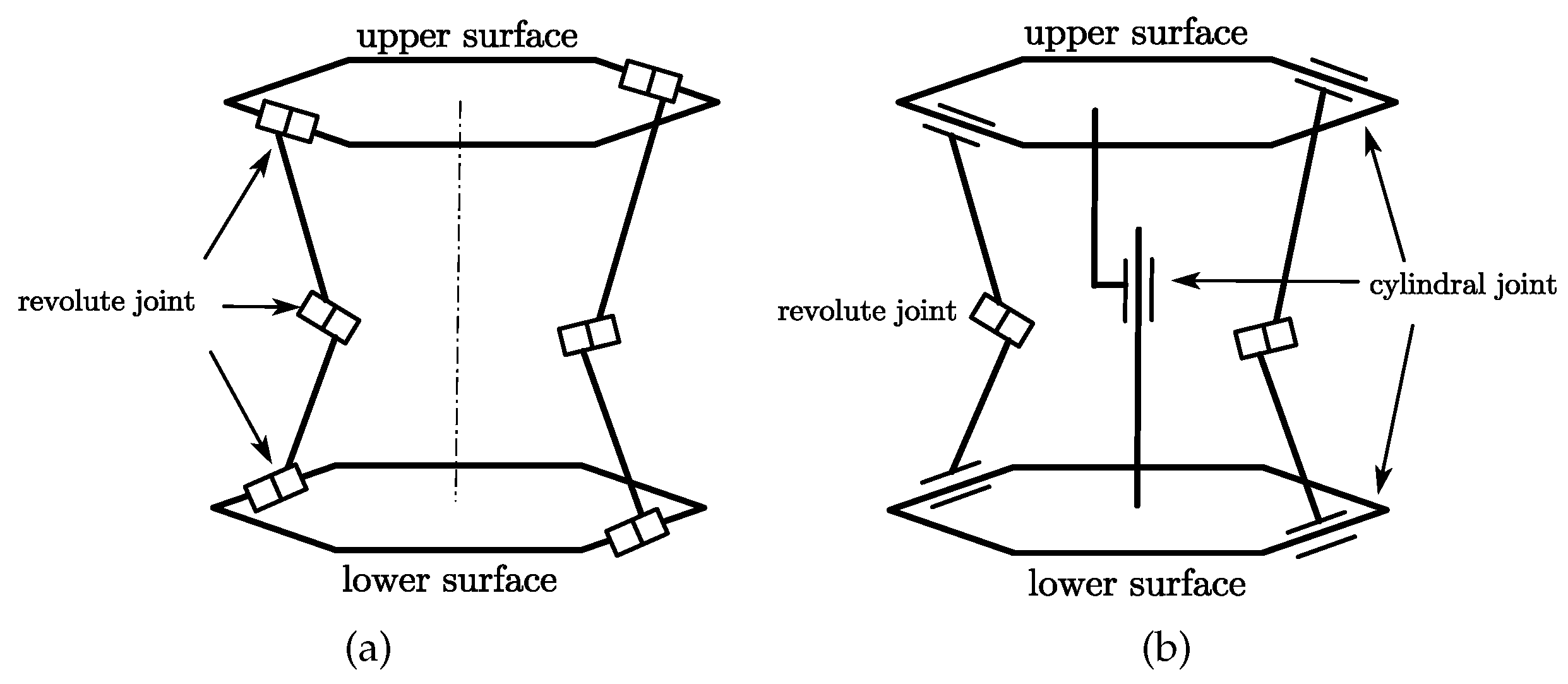
The Kresling structure, arranged alternately by a series of triangular peaks and valleys to connect the upper and lower planes, is spiral in shape. It has a large folding ratio and good deployability. It has great advantages in applications requiring a large folding ratio. During folding and unfolding, the angle between each side valley crease and the upper and lower planes changes. The angle increases when the mechanism is extended and decreases when it is retracted. The movability of the Kresling structure is based on the flexible deformation of paper. Its deformation presents a bistable form. [
24]. If the paper is assumed to be rigid and the crease is a revolute joint, then the entire structure is immovable. Considering that the rotor hub rotates at high speed during operation and the fluid’s force on the structure is complex and variable, the bistable structure relies on material flexibility to ensure the movability of the mechanism. When applied to a rotor, it is difficult to ensure stability. Therefore, the Kresling structure is improved. The revolute joint connection between the triangular piece and the upper and lower planes in the Kresling structure is changed to a cylindrical joint connection. A cylindrical joint connection is added between the upper and lower planes. The Kresling origami and the modified structure are shown in
Figure 1a,b.
The improved Kresling structure is a single-degree-of-freedom structure. The angle between the side link and the base plane is defined as
, the angle between the axis of the side revolute joint and the upper and lower planes is defined as
, and the angle between the axes of the two revolute joints fixedly connected with the side link is defined as
, as shown in
Figure 2. The relationship among these angles can be described by Equation (
1).
2.2. Spherical Four-Bar Mechanism
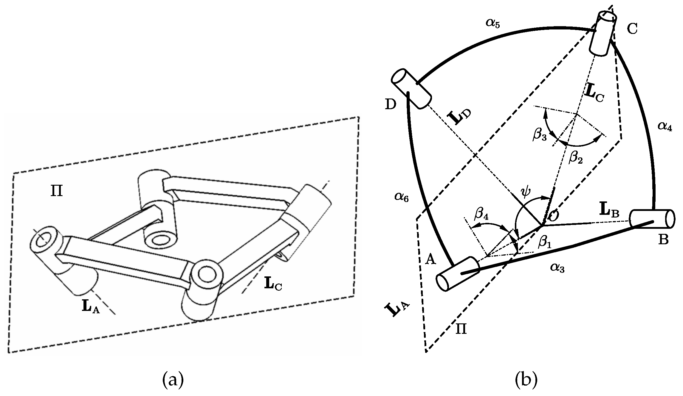
The spherical four-bar mechanism is a spatial mechanism in which the axes of the revolute joints intersect at a point. The trajectory of the constructed point is located on a concentric spherical surface. Let
,
,
, and
represent the axes of each revolute joint, which are intersected at the center of the sphere
O. Let
represents the torsion angles between the revolute joints. Let the angle between
and
be
, and form a plane
.
respectively represent the angles between
and the planes AOB, BOC, COD, DOA. Let
. The above mentioned geometric relationship is expressed in
Figure 3.
Rich spatial deformations can be produced by the spherical four-bar mechanism. Considering modular design and for the purpose of simplifying the design steps, in this paper, two specific forms of spherical four-bar mechanisms, namely the oblique symmetric spherical four-bar mechanism and the equilateral spherical four-bar mechanism, are employed to construct a spatial scissor mechanism.
The oblique symmetric spherical four-bar mechanism has equal opposite side links. Its geometric constraint can be described as Equation (
2).
can be obtained by Equation(
3).
Where
s represents sin and
c represents cos. The geometric constraint of the equilateral spherical four-bar mechanism can be described as (
5). The remaining shape parameters have a similar form to those of the oblique symmetric type.
3. Deformation Driving Mechanism
The variable blade angle hub and spherical linkages are composed to form the deformation drive mechanism. The design of the hub is applied with the change in the angle
between the axis of the revolute joint of the Kresling origami structure and the base plane, as shown in
Figure 2. The blade deformation drive structure is formed by the oblique symmetric and equilateral spherical four-bar structures which act as the deformation units(s-units) of the blade and are connected in series.
3.1. Variable Blade Angle Hub
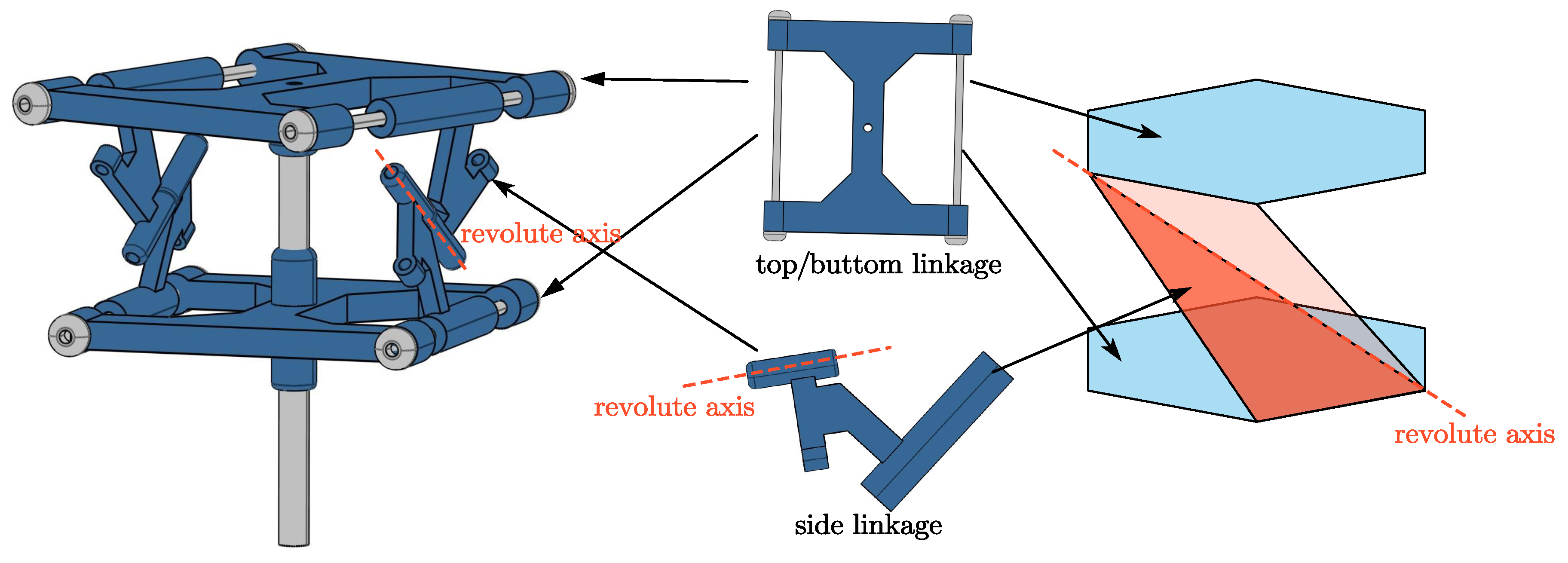
Six spatial linkages are composed to form the hub. The upper and lower linkages are connected by a cylindrical pair. A cylindrical pair connection exists between the side linkage and the base linkage. Additionally, there is a revolute joint connection between the side connecting rods. The axis of the revolute joint is defined as
. The mechanism schematic of the propeller hub is presented in
Figure 4.
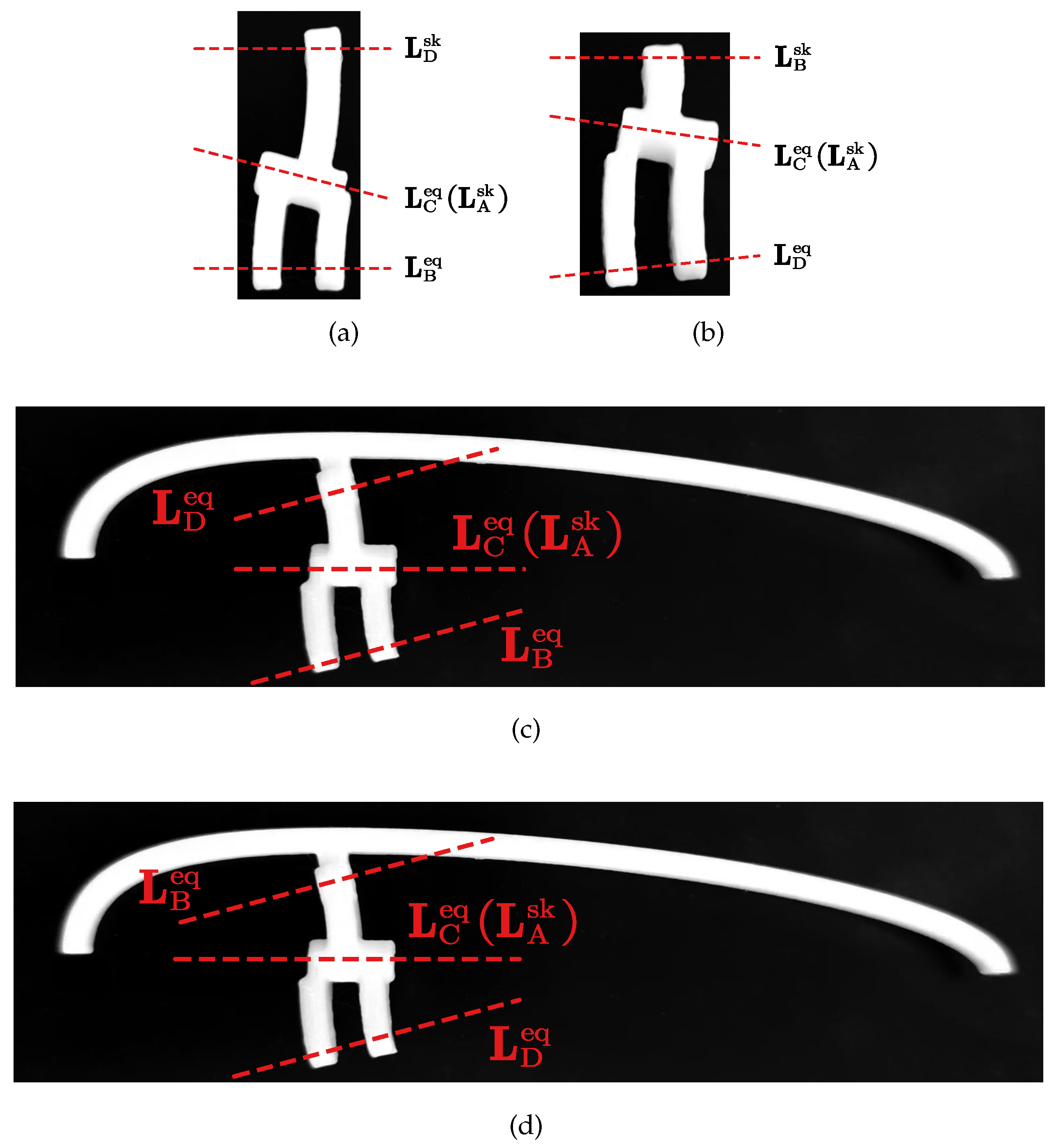
When the hub deforms, the angle between
and the base plane changes. The chord line of the root section of the propeller blade is set parallel to , enabling the hub to generate installation angle deformation. The deformation of the hub and installation angle is shown in
Figure 5.
3.2. Extensional-Torsional Deformable Blade
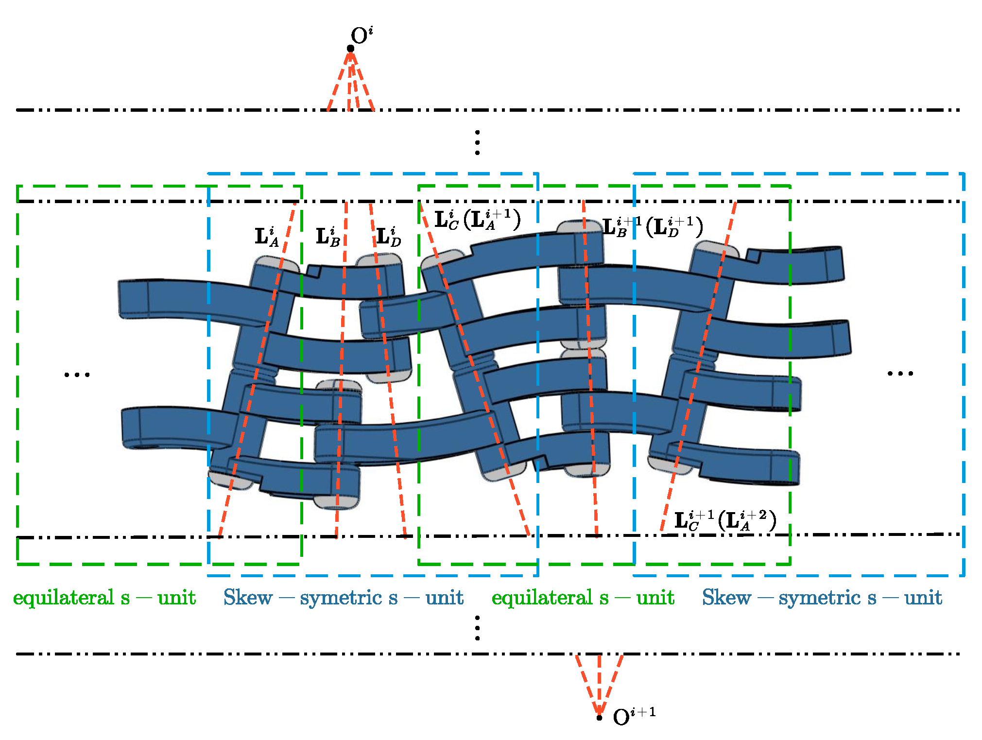
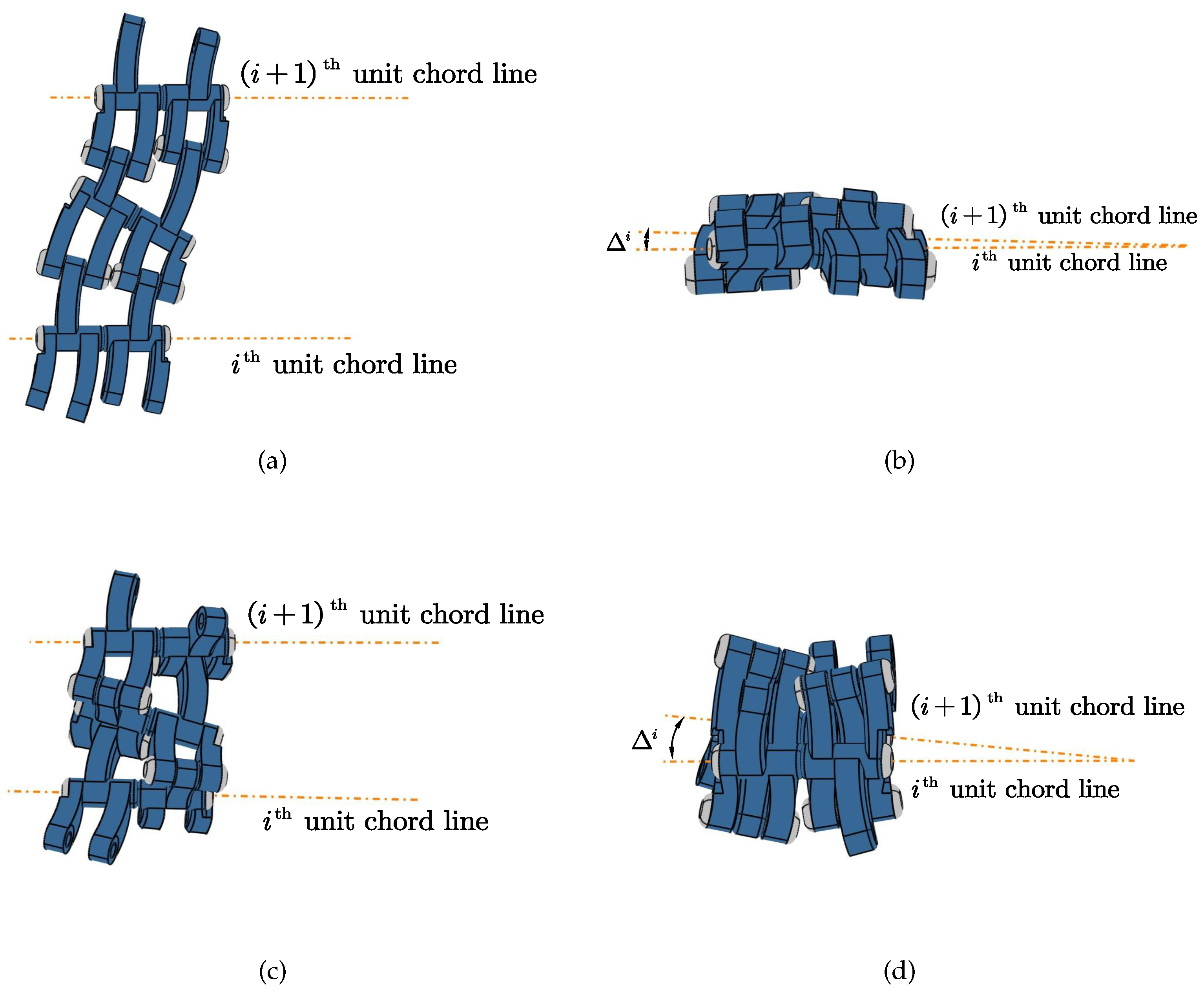
The driving mechanism of the deformable blade is formed by alternately arranging and serially connecting equilateral s-units and oblique symmetric s-units. In the series sequence, a four-bar mechanism is referred to as an s-unit. The shape parameters described in
Figure 3 are added with a superscript
to depict the shape of the
s-unit. The
of the
s-unit coincides with the
of the
s-unit. The linkage
of the
unit is fixed connected to the linkage
of the
unit. The mechanism schematic of serial connected s-units is shown in
Figure 6.
When the propeller deforms from the aerial mode to the underwater mode, the distance between the chord lines of the propeller blade sections is reduced and the angle between the chord lines is increased. The serially connected s-units possess the coupled motion characteristics of extension and torsion, which are necessary for the deformation of the Aerial-aquatic propeller, as is depicted in
Figure 7.
3.3. Variable Thickness Rib Structure
The blade rib support is segmented into upper and lower parts along the chord line and is fixed connected to linkage AB and linkage DA of the equilateral s-unit respectively. The chord line of the blade rib coincides with
, thus the blade thickness undergoes deformation as the s-sequence deform, as is depicted in
Figure 8.
3.4. Propeller Deformation Driving Mechanism
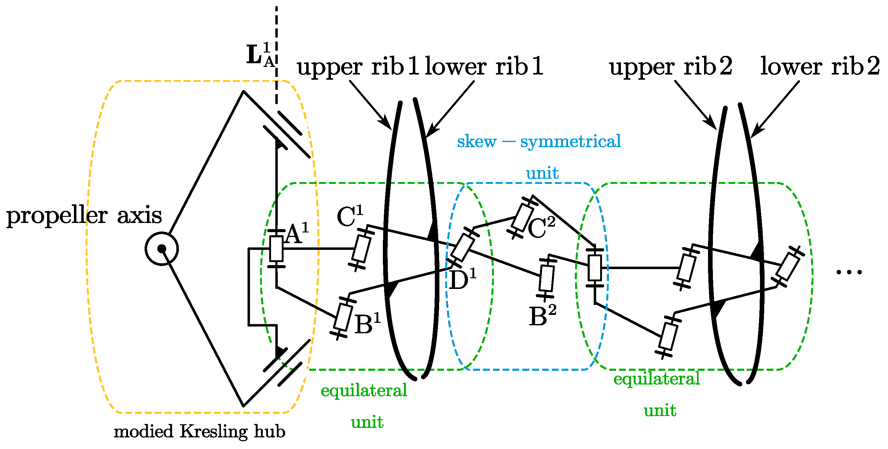
The propeller deformation mechanism is assembled by the aforementioned deformable hub and blade. The side linkages of the deformable hub act as the linkage AB and linkage DA of the blade root unit. The axis of the revolute joint of the hub coincides with
. The blade rib support structure is installed on each equilateral s-unit. The schematic diagram of the propeller deformation driving mechanism is depicted in
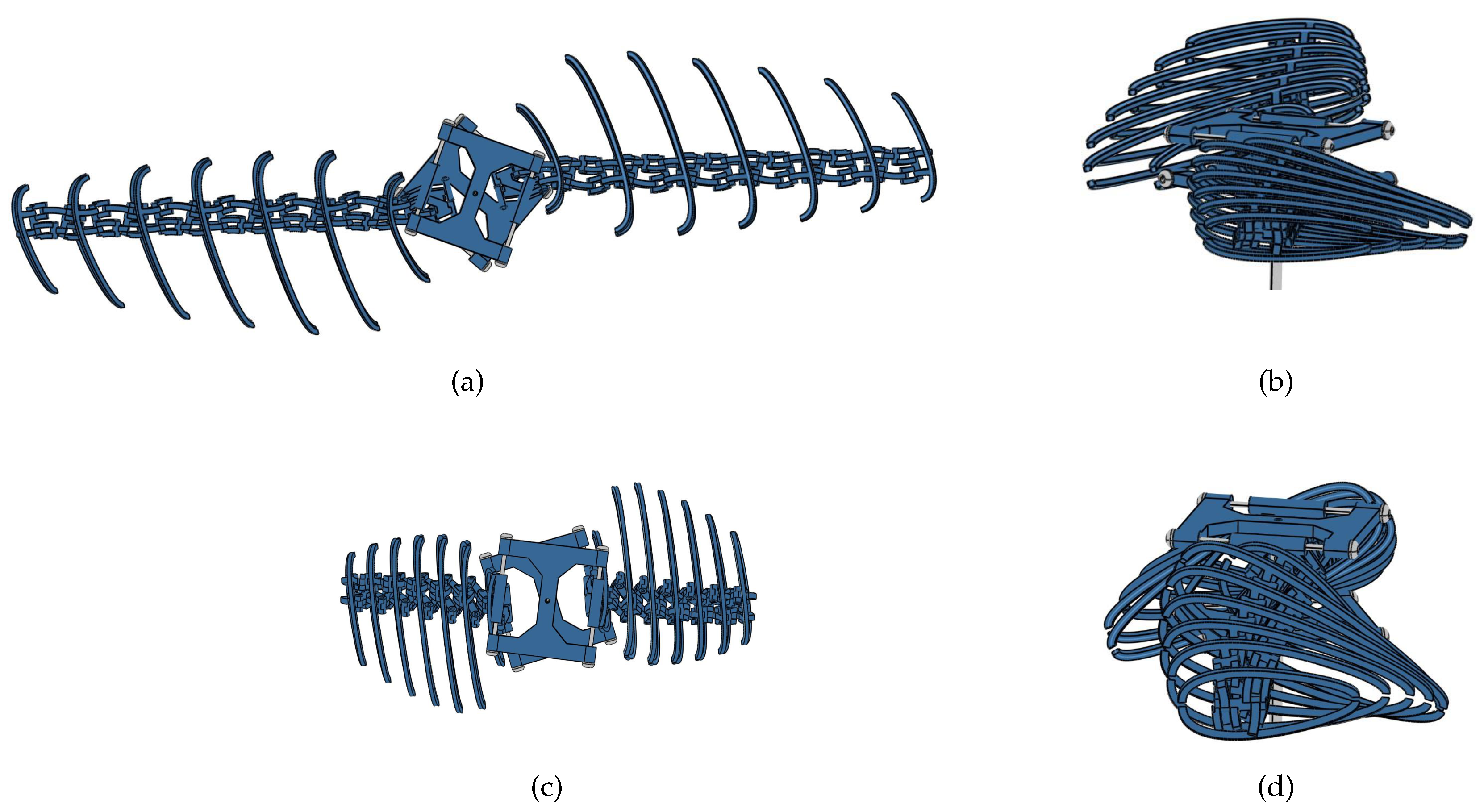
Figure 9. The shapes of the deformation mechanism in the air and underwater are presented in
Figure 10. It can be observed that the designed mechanism fits the shapes of the propeller in the aerial mode and aquatic mode rather well.
4. Kinematic Analysis
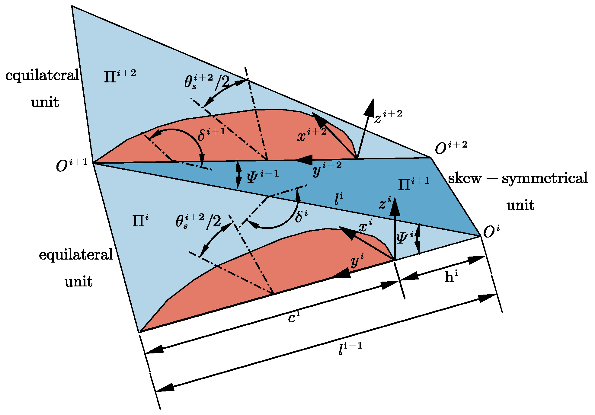
For the clarity of the kinematic description of the mechanism, a rectangular coordinate system is defined on each s-unit with the installed wing rib support structure. The origin of the coordinate system coincides with the leading edge of the blade section. The x-axis is set on the
plane of the s-unit and perpendicular to the chord line of the blade rib. The y-axis coincides with the chord line of the wing rib, and the z-axis is perpendicular to the plane. The angle between the
plane and the
plane is defined as
, as is shown in
Figure 11.
4.1. Shape Parameterization of Blade Section
The section shape of the propeller blade is determined by the shape and folding degree of the blade rib support structure. The shapes of the upper and lower half wing rib support structures
and
can be respectively described as two B-spline curves of degree 3 with 15 control points, as shown in Equation (
6).
Where,
is the B-spline basis function,
and
represent the coordinates of the control points. The folding degree of the blade rib can be described by
of the equilateral s-unit. Therefore, in the coordinate system, the control points of the real section shape can be described as Equation (
7).
4.2. Shape Parameterization of s-Units
If a rib support is equipped on the
section, the next rib support be arranged on the
section. The relative positions of the chord lines at the two wing rib sections can be described by
,
, and
. As shown in
Figure 11, the relative positions of the two s-units can be described by the coordinate transformation method as Equation (
8).
Where,
represents the SE(3) translation transformation matrix in the y-axis direction, as is shown in Equation (
9).
represents the SE(3) rotation transformation matrix around the z-axis, as is shown in Equation (
10).
represents the SE(3) rotation transformation matrix around the y-axis, as is shwon in Equation (
11).
The control points of the
section shape can be described as Equation (
12). Then, the blade shape can be described by a B-spline surface composed of the control points of the blade rib shape.
Where,
is composed of upper and lower half rib control points, as is shown in Equation (
13).
4.3. Deformation Analysis
4.3.1. Extension Deformation
Referring to
Figure 11, two adjacent blade rib support are connected by an equilateral and an oblique symmetric spherical four-bar linkage. During the deformation process, the change of
results in extensional deformation. As the shape coefficients difference in oblique symmetric unit and equilateral unit, two adjacent section are not parallel, thus,
is used to define the distance of two sections, as is shown in Equation (
14).
Where,
can be obtained by Equation (
3). Obviously,
directly influences the size of the blade, an extension ratio
is defined to describe the deformation characterization, as is shown in Equation (
15).
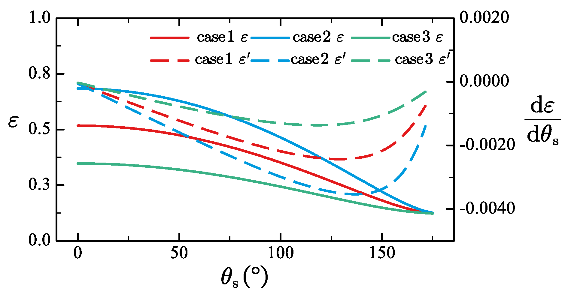
To investigate the influence of the shape parameters of the s-unit on the expansion rate, three calculation examples are set up. The parameter settings are shown in the following
Table 1.
The relationship between
and
is shown in
Figure 12. As can be seen from the figure, for a given
, when the linkage angle is larger, the expansion rate is larger. When
is around 125 degrees, the derivative of the expansion rate with respect to
can obtain a relatively large value. When the mechanism is fully folded or extended, the amplitude of extension deformation is relatively small.
4.3.2. Torsion Deformation
Planes
and
perform a folding motion around the axis of
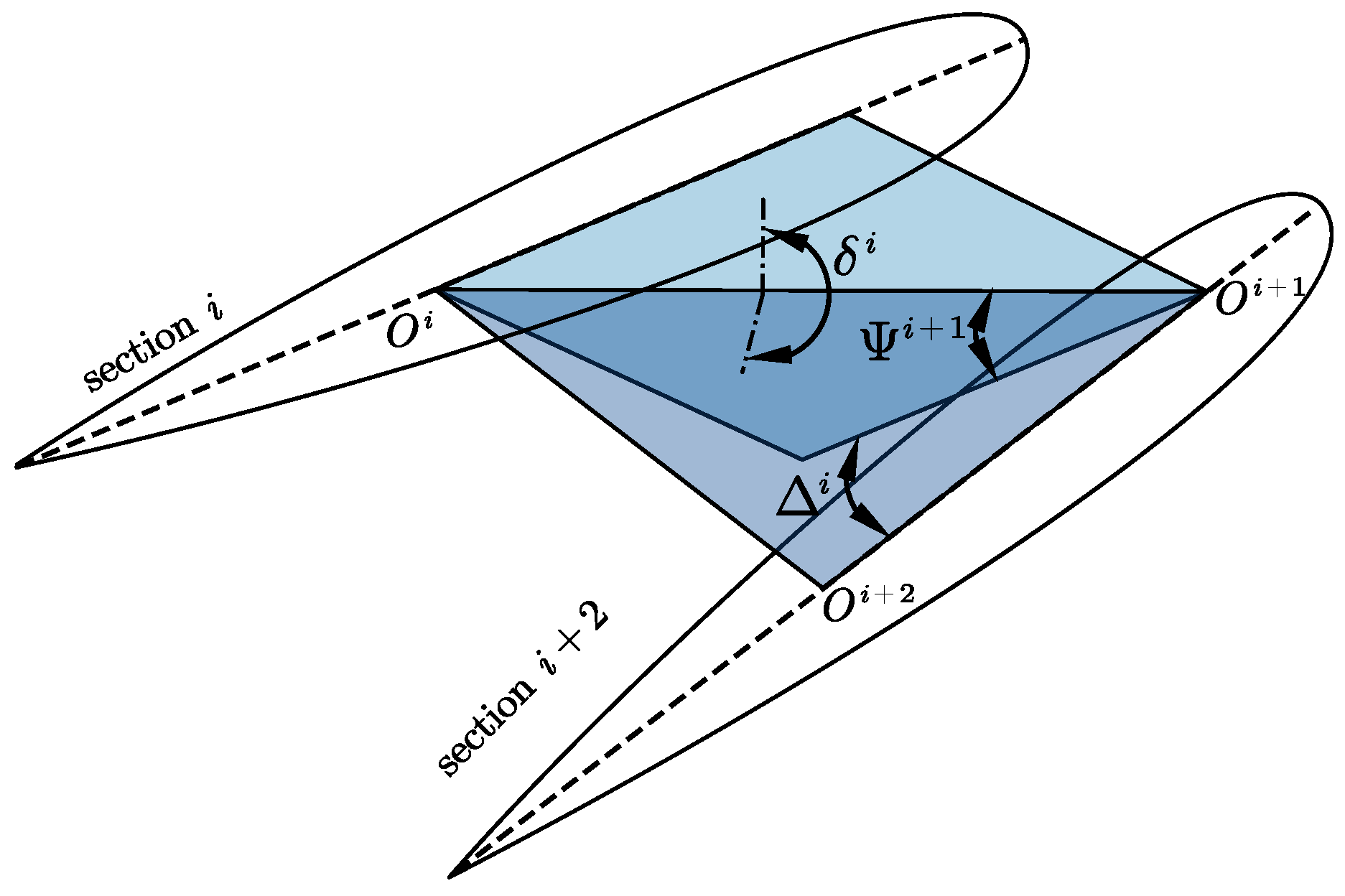
, resulting in the torsional deformation of the blade. As mentioned above, the relative motion between sections is not strictly translational motion, thus, there is a changing angle between two adjacent sections. The torsion angle
can be defined as angle between
and
.
represents the projection of
, as is shown in
Figure 13.
In coordinate system
,
can be obtained by Equation (
16).
Where
can be obtained by Equation (
17).
The folding angle
can be obtained by Equation (
18).
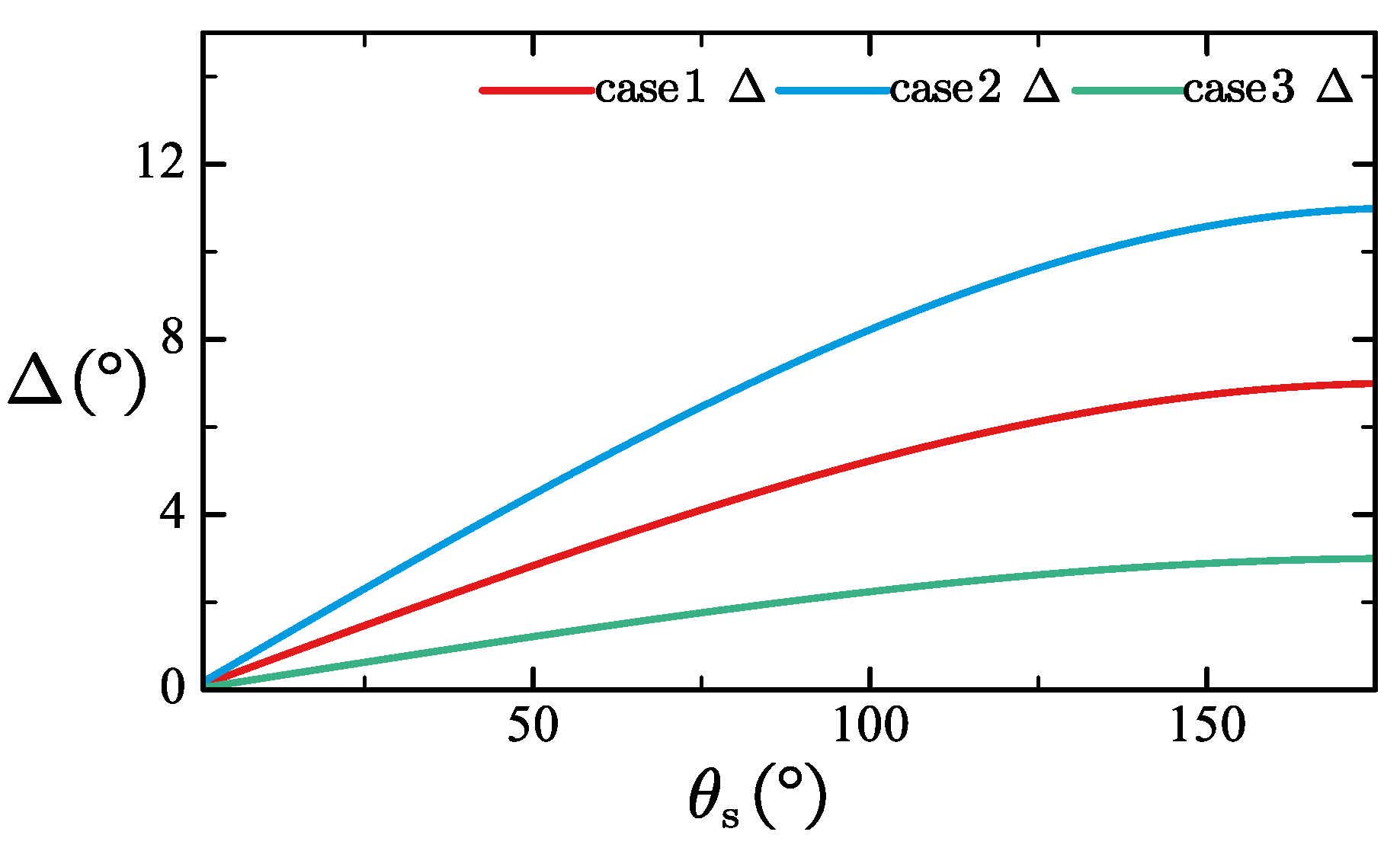
To investigate the influence of the shape parameters of the s-unit on the torsional angle, three calculation examples are set up. The parameter settings are shown in the following
Table 2.
The relationship between
and s-unit coefficients is shown in
Figure 14.
It can be seen that the greater the difference between
and
of the oblique symmetric unit, the more intense the torsional deformation. When the mechanism is fully extended, the derivative of the torsion angle is close to 0. The blade angle
is driven by the modified Kresling hub, which can be obtained by Equation (
1). The attack angle distribution can be obtained by Equation (
19).
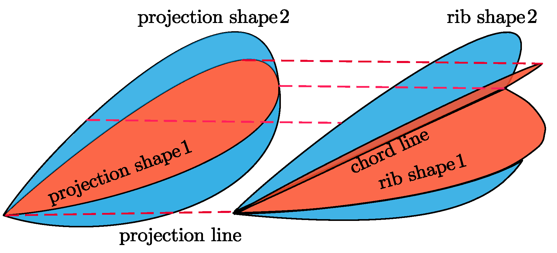
4.3.3. Thickness Deformation
As the upper and lower rib structure are connected to BC and CD linkages respectively, their rotation around
results in thickness deformation, as is shown in
Figure 8. If an angle is set between the wing rib plane and the connecting rod plane, more abundant thickness changes can be achieved. However, for the consideration of improving the strength of the mechanism, the rib plane is set to coincide with the linkage plane. Thus, points on the rib structure
can be expressed in section coordinate system in form of Equation (
20). The schematic diagram of thickness variation is shown in
Figure 15. The shape of the real airfoil can be obtained by Equation (
7).
5. Simulation and Rapid Prototyping Experiment
To verify the deformation characteristics of the deformation driving mechanism, kinematic simulation based on the Digital mock-up module of CATIA was carried out. Also, a rapid prototype based on 3-D printing were manufactured. The prototype is composed of seven identical equilateral s-units and seven identical skew-symmetrical s-units. A blade rib support structure is installed on each equilateral s-unit. The shape parameters are shown in
Table 3.
In kinematic simulation, an displacement driving point is set on the upper linkage of the propeller hub, as is shown in
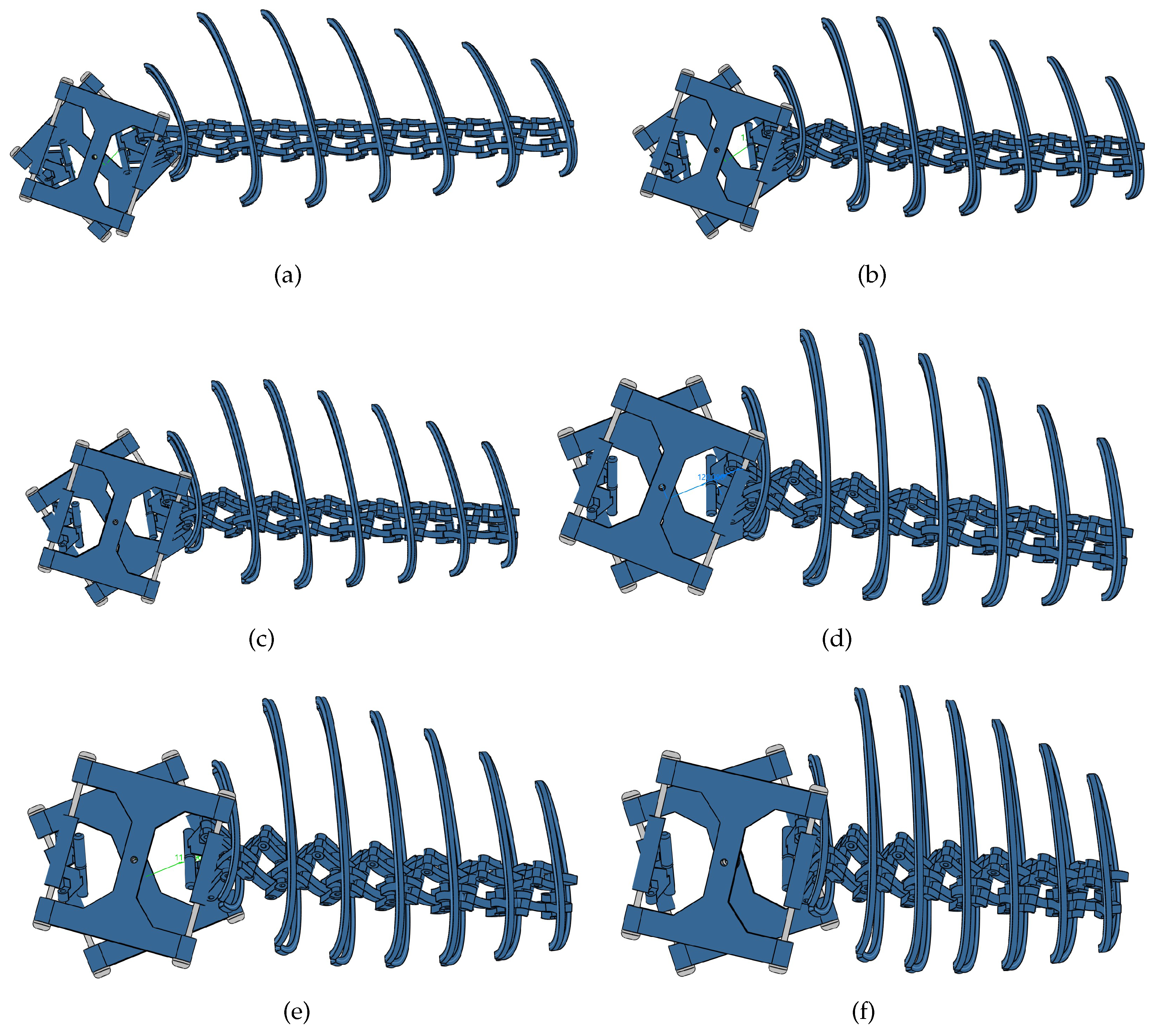
Figure 16. The deformation process is shown in
Figure 17.
As can be seen from
Figure 18,
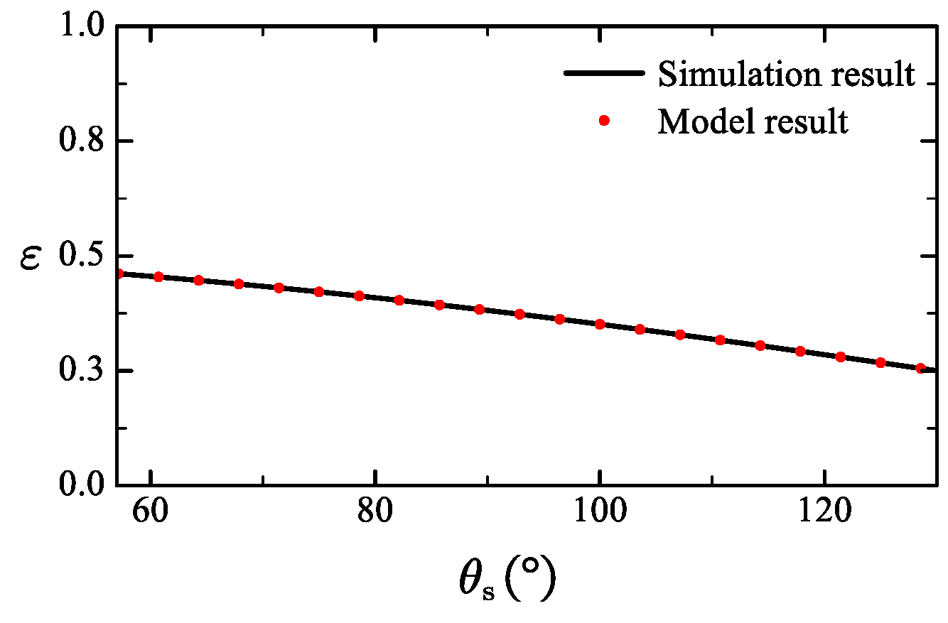
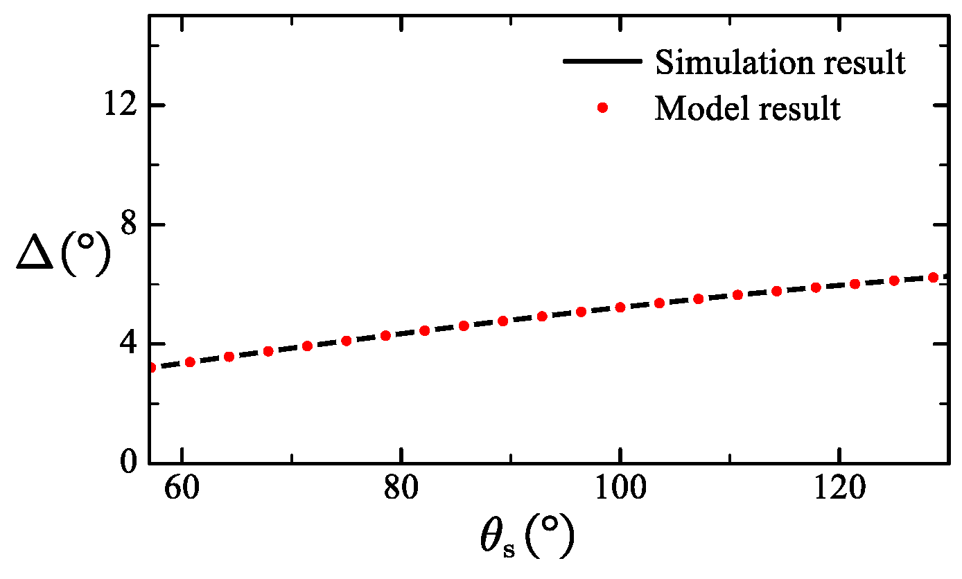
Figure 19 and
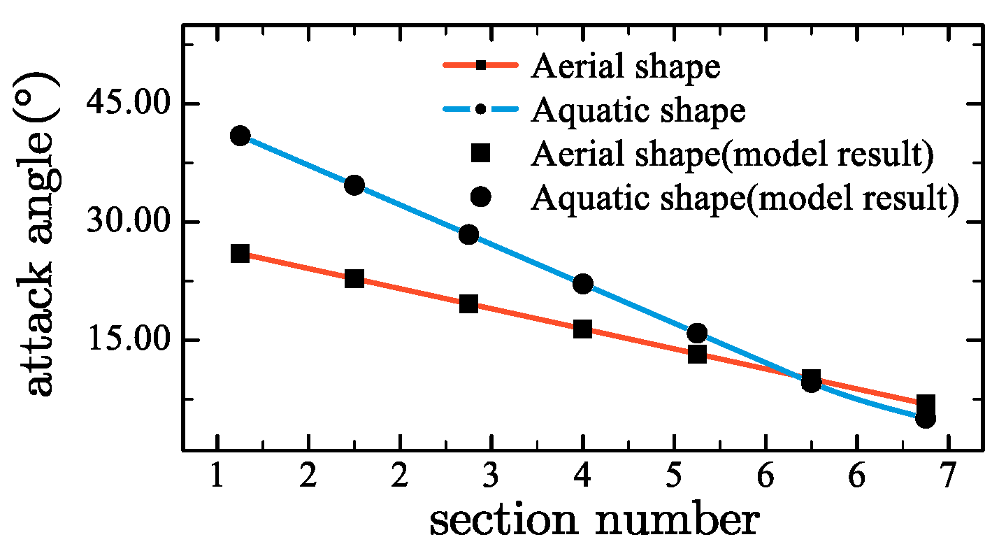
Figure 20, the simulation results are in agreement with the calculation results of the proposed kinematic model. The simulation results shows that the proposed mechanism is a single-degree-of-freedom mechanism and there is no interference during deformation. According to simulation results, the radius of the propeller in the aerial form is 263.872 mm, and the disk ratio is 0.204. In the underwater form, the radius is 178.285 mm, and the disk ratio is 0.346. The attack angle distribution of the rotor in the air and underwater are shown in
Figure 18. It can be seen that under the drive of the designed mechanism, the propeller presents a more slender shape in the air, with a larger radius and a smaller disk ratio, which helps to increase the rotational speed during flight and increase lift. When working underwater, the radius of the propeller decreases and the disk ratio increases, which helps to reduce cavitation effects and improve work efficiency. Driven by the Kresling hub, the installation angle of the blade in the aerial shape is 24.862
, and it increases to 41.476
underwater. This makes the propeller adapt to working conditions with a higher advance coefficient when working in water. Since the shapes of the blade deformation units are the same, the attack angle distribution of the blade is linearly distributed. It can be seen that the designed mechanism can effectively drive the propeller to deform between the aerial shape and the underwater shape.
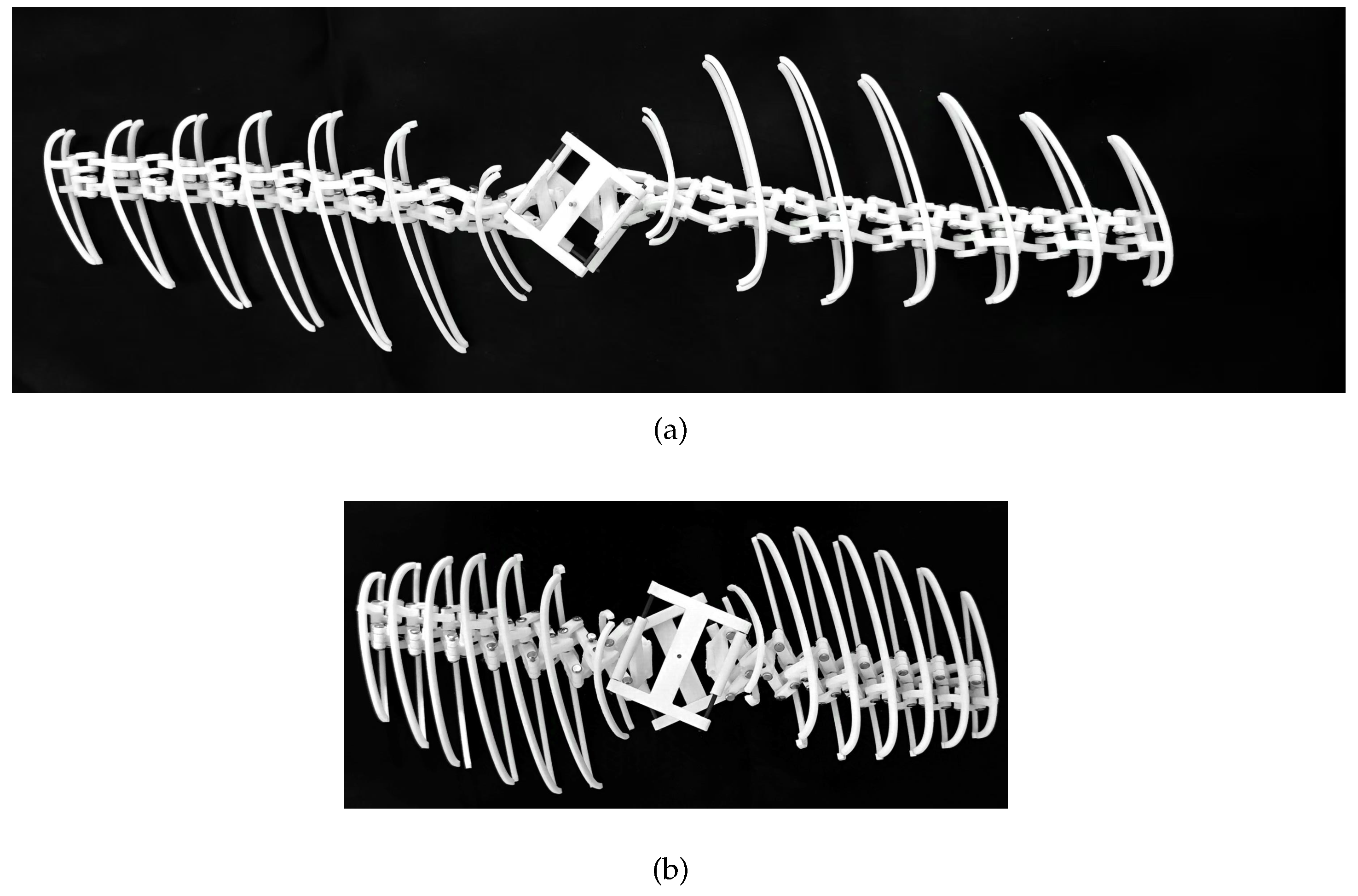
To verify the feasibility of the designed mechanism, a trial production of a rapid prototype was carried out. The shape parameters of the rapid prototype are the same as those in the simulation. The diameter of the revolute joint shaft is 2 mm, and the wall thickness of each part is 5 mm. The rapid prototype mechanism is manufactured by 3-D printing technology. Some parts of the prototype are shown in
Figure 21. The blade rib part is the wing rib of the third section. The shape parameters of the other wing ribs are the same as those of the third wing rib, and the sizes of the wing ribs are slightly different. The shapes of the prototype in the air and underwater are shown in
Figure 22.
It can be seen that the mechanism has a larger radius, a slender shape in the air. Both section twist angle and blade angle are small. When deformed into an underwater shape, the blade radius is significantly reduced, the disk ratio is increased, the section twist angle is increased, and the blade angle is increased. This indicates that the designed mechanism can effectively drive the propeller to deform between the two shapes in the air and underwater.
However, due to manufacturing technology limitations, the overall size and weight of the blade are relatively large. Although the blade has better stability and self-supporting property in the underwater shape. When the blade is deformed into aerial shape, there is a slight deformation at the blade root, and the overall shape is drooping. In subsequent work, attention should be paid to structural strength issues.
6. Conclusions
In this paper, according to the shape characteristics of aerial propellers and underwater propellers, a driving mechanism with the deformation capabilities of installation angle, radius, twist angle distribution, and section thickness is designed. Through motion analysis, simulation, and rapid prototype testing, the following conclusions are obtained.
The modified Kresling structure can be effectively applied to the design of hubs with variable installation angles. The spherical space scissor structure composed of equilateral s-units and oblique symmetric s-units alternately has the deformation ability of telescopic-torsional coupling and is suitable as the deformation driving structure of the deformable propeller blades for amphibious applications in water and air.
By comparing the motion simulation results and the calculation structure of the proposed motion model, it is proved that the mechanism kinematics model based on the coordinate transformation method can accurately describe the deformation characteristics of the propeller.
Through kinematic analysis and simulation, it is found that the designed structure can significantly change the radius and installation angle of the propeller. When equilateral s-units and skew-symmetrical s-units with the same shape parameters are used to form the blade deformation mechanism, the blade attack angle is linearly distributed before and after deformation.
Through rapid prototype testing, the motion characteristics of the deformation mechanism are verified. There is no interference or singularity in the deformation process, and the mechanism operate stably.
The overall structure is relatively heavy, and there is a slight deformation at the blade root, resulting in a drooping phenomenon of the blade in the aerial state. In subsequent work, attention needs to be paid to structural strength issues.
References
- Yao, G.; Li, Y.; Zhang, H.; Jiang, Y.; Wang, T.; Sun, F.; Yang, X. Review of hybrid aquatic-aerial vehicle (HAAV): Classifications, current status, applications, challenges and technology perspectives. Progress in Aerospace Sciences 2023, 139, 100902. [Google Scholar] [CrossRef]
- Ma, Z.; Chen, D.; Li, G.; Jing, X.; Xiao, S. Configuration design and trans-media control status of the hybrid aerial underwater vehicles. Applied Sciences 2022, 12, 765. [Google Scholar] [CrossRef]
- Farinha, A.T.; Di Tria, J.; Reyes, M.; Rosas, C.; Pang, O.; Zufferey, R.; Pomati, F.; Kovac, M. Off-shore and underwater sampling of aquatic environments with the aerial-aquatic drone MEDUSA. Frontiers in Environmental Science 2022, 10, 1023269. [Google Scholar] [CrossRef]
- Sánchez-García, J.; García-Campos, J.M.; Arzamendia, M.; Reina, D.G.; Toral, S.; Gregor, D. A survey on unmanned aerial and aquatic vehicle multi-hop networks: Wireless communications, evaluation tools and applications. Computer Communications 2018, 119, 43–65. [Google Scholar] [CrossRef]
- Deng, F.; Sun, X.; Chi, F.; Ji, R. A Numerical Study on the Water Entry of Cylindrical Trans-Media Vehicles. Aerospace 2022, 9, 805. [Google Scholar] [CrossRef]
- Yuan, S.; Li, Y.; Bao, F.; Xu, H.; Yang, Y.; Yan, Q.; Zhong, S.; Yin, H.; Xu, J.; Huang, Z.; others. Marine environmental monitoring with unmanned vehicle platforms: Present applications and future prospects. Science of The Total Environment 2023, 858, 159741. [Google Scholar] [CrossRef] [PubMed]
- Lawson, J.; Farinha, A.; Romanello, L.; Pang, O.; Zufferey, R.; Kovac, M. Use of an unmanned aerial-aquatic vehicle for acoustic sensing in freshwater ecosystems. Remote Sensing in Ecology and Conservation 2024, 10, 343–359. [Google Scholar] [CrossRef]
- Jin, Y.; Bi, Y.; Lyu, C.; Bai, Y.; Zeng, Z.; Lian, L. Nezha-IV: A hybrid aerial underwater vehicle in real ocean environments. Journal of Field Robotics 2024, 41, 420–442. [Google Scholar] [CrossRef]
- Wu, S.; Shao, M.; Wu, S.; He, Z.; Zhang, J.; Liu, Y. ; others. A high maneuvering motion strategy and stable control method for tandem twin-rotor aerial-aquatic vehicles near the water surface. Defence Technology.
- Siddall, R.; Kovač, M. Launching the AquaMAV: bioinspired design for aerial–aquatic robotic platforms. Bioinspiration & biomimetics 2014, 9, 031001. [Google Scholar]
- Sun, Y.; Liu, X.; Cao, K.; Shen, H.; Li, Q.; Chen, G.; Xu, J.; Ji, A. Design and Theoretical Research on Aerial-Aquatic Vehicles: A Review. Journal of Bionic Engineering 2023, 20, 2512–2541. [Google Scholar] [CrossRef]
- Liu, S.; Du, C.; Han, Y.; Zhang, Y.; Lin, W.; Cai, Y.; Wang, T. Research on Hydrodynamics of Trans-Media Vehicles Considering Underwater Time-Varying Attitudes. Journal of Marine Science and Engineering 2024, 12, 1338. [Google Scholar] [CrossRef]
- Li, J.; Chen, S.; Guo, M.; Tao, T.; Li, R. Underwater dynamics modeling and simulation analysis of trans-media multicopter. 2021 5th International Conference on Robotics and Automation Sciences (ICRAS). IEEE, 2021, pp. 116–122.
- Song, C.; Xu, H.; Zhang, L.; Chen, H. Variable Structure Water-Air Amphibious Trans-media Vehicle Concept Design and Characteristic Analysis. International Conference on Autonomous Unmanned Systems. Springer, 2023, pp. 91–101.
- Drews, P.L.; Neto, A.A.; Campos, M.F. Hybrid unmanned aerial underwater vehicle: Modeling and simulation. 2014 IEEE/RSJ International Conference on Intelligent Robots and Systems. IEEE, 2014, pp. 4637–4642.
- Horn, A.C.; Pinheiro, P.M.; Silva, C.B.; Neto, A.A.; Drews-Jr, P.L. A study on configuration of propellers for multirotor-like hybrid aerial-aquatic vehicles. 2019 19th International Conference on Advanced Robotics (ICAR). IEEE, 2019, pp. 173–178.
- Alzu’bi, H.; Akinsanya, O.; Kaja, N.; Mansour, I.; Rawashdeh, O. Evaluation of an aerial quadcopter power-plant for underwater operation. 2015 10th International Symposium on Mechatronics and its Applications (ISMA). IEEE, 2015, pp. 1–4.
- Alzu’bi, H.; Mansour, I.; Rawashdeh, O. Loon copter: Implementation of a hybrid unmanned aquatic–aerial quadcopter with active buoyancy control. Journal of field Robotics 2018, 35, 764–778. [Google Scholar] [CrossRef]
- Tan, Y.H.; Chen, B.M. Design of a morphable multirotor aerial-aquatic vehicle. Oceans 2019 Mts/IEEE Seattle. IEEE, 2019, pp. 1–8.
- Tan, Y.H.; Chen, B.M. A morphable aerial-aquatic quadrotor with coupled symmetric thrust vectoring. 2020 IEEE International Conference on Robotics and Automation (ICRA). IEEE, 2020, pp. 2223–2229.
- Tan, Y.H.; Chen, B.M. Underwater stability of a morphable aerial-aquatic quadrotor with variable thruster angles. 2021 IEEE International Conference on Robotics and Automation (ICRA). IEEE, 2021, pp. 314–320.
- Wang, W.; Wang, L.; Zhang, K.; Huang, Y. Lift–Drag Performance of a New Unmanned Aerial Vehicle in Different Media and Ground Effect. Journal of Marine Science and Engineering 2024, 12, 1052. [Google Scholar] [CrossRef]
- Liao, F.; Ye, D. Disturbance Observer-Based Robust Take-Off Control for a Semi-Submersible Permeable Slender Hybrid Unmanned Aerial Underwater Quadrotor. Applied Sciences 2023, 13, 9318. [Google Scholar] [CrossRef]
- Kidambi, N.; Wang, K. Dynamics of Kresling origami deployment. Physical Review E 2020, 101, 063003. [Google Scholar] [CrossRef] [PubMed]
Figure 1.
Mechanism schematics of Kresling origami and modified Kresling origami. (a) Kresling origami (b) modified Kresling origami.
Figure 1.
Mechanism schematics of Kresling origami and modified Kresling origami. (a) Kresling origami (b) modified Kresling origami.
Figure 2.
Geometric schematic of the Kresling structure
Figure 2.
Geometric schematic of the Kresling structure
Figure 3.
Mechanism schematics of spherical 4 bar mechanism. (a) 3-D geometrical model schematic (b) mechanism brief schematics
Figure 3.
Mechanism schematics of spherical 4 bar mechanism. (a) 3-D geometrical model schematic (b) mechanism brief schematics
Figure 4.
Mechanism schematic of the propeller hub
Figure 4.
Mechanism schematic of the propeller hub
Figure 5.
Mechanism schematics of a Kresling Hub. (a) Hub shape a (b) Hub shape b (c) Hub shape c (d) Hub shape d
Figure 5.
Mechanism schematics of a Kresling Hub. (a) Hub shape a (b) Hub shape b (c) Hub shape c (d) Hub shape d
Figure 6.
Mechanism schematic of serial connected s-units
Figure 6.
Mechanism schematic of serial connected s-units
Figure 7.
Schematic diagram of serial connected s-units deformation. (a) top view of aerial shape (b) side view of aerial shape (c) top view of aquatic shape (d) side view of aquatic shape
Figure 7.
Schematic diagram of serial connected s-units deformation. (a) top view of aerial shape (b) side view of aerial shape (c) top view of aquatic shape (d) side view of aquatic shape
Figure 8.
Schematic diagram of blade section deformation. (a) aerial shape (b) aquatic shape
Figure 8.
Schematic diagram of blade section deformation. (a) aerial shape (b) aquatic shape
Figure 9.
Schematic diagram of deformation driving mechanism
Figure 9.
Schematic diagram of deformation driving mechanism
Figure 10.
Deformation of the deformation driving mechanism. (a) top view of aerial shape (b) side view of aerial shape (c) top view of aquatic shape (d) side view of aquatic shape
Figure 10.
Deformation of the deformation driving mechanism. (a) top view of aerial shape (b) side view of aerial shape (c) top view of aquatic shape (d) side view of aquatic shape
Figure 11.
Schematic diagram of coordinate system
Figure 11.
Schematic diagram of coordinate system
Figure 12.
Data graph of extensional ratio
Figure 12.
Data graph of extensional ratio
Figure 13.
Schematic diagram of torsional deformation
Figure 13.
Schematic diagram of torsional deformation
Figure 14.
Data graph of torsional deformation
Figure 14.
Data graph of torsional deformation
Figure 15.
Schematic diagram of thickness variation
Figure 15.
Schematic diagram of thickness variation
Figure 16.
Schematic diagram of the layout of drive points
Figure 16.
Schematic diagram of the layout of drive points
Figure 17.
Mechanism shape of different . (a) (b) (c) (d) (e) (f)
Figure 17.
Mechanism shape of different . (a) (b) (c) (d) (e) (f)
Figure 18.
Data graph of attack angle distribution
Figure 18.
Data graph of attack angle distribution
Figure 19.
Data comparison chart of extensino ratio
Figure 19.
Data comparison chart of extensino ratio
Figure 20.
Data comparison chart of attack angle distribution
Figure 20.
Data comparison chart of attack angle distribution
Figure 21.
Parts of propeller morphing mechanism (a) parts of equilateral unit BC linkage and oblique symmetric unit AD linkage(b) parts of equilateral unit DC linkage and oblique symmetric unit AB linkage(c) parts of upper half rib structure (d) parts of lower half rib structure
Figure 21.
Parts of propeller morphing mechanism (a) parts of equilateral unit BC linkage and oblique symmetric unit AD linkage(b) parts of equilateral unit DC linkage and oblique symmetric unit AB linkage(c) parts of upper half rib structure (d) parts of lower half rib structure
Figure 22.
Propeller morphing mechanism (a) aerial shape of the mechanism (b) aquatic shape of the mechanism
Figure 22.
Propeller morphing mechanism (a) aerial shape of the mechanism (b) aquatic shape of the mechanism
Table 1.
Table of shape coefficients
Table 1.
Table of shape coefficients
| |
example 1 |
example 2 |
example 3 |
|
15 |
20 |
10 |
|
18.5 |
23.5 |
13.5 |
|
11.5 |
16.5 |
6.5 |
Table 2.
Table of shape coefficients
Table 2.
Table of shape coefficients
| |
example 1 |
example 2 |
example 3 |
|
15 |
15 |
15 |
|
18.5 |
20.5 |
16.5 |
|
11.5 |
9.5 |
13.5 |
Table 3.
Table of shape coefficients
Table 3.
Table of shape coefficients
| shape coefficient |
value |
meaning |
|
42.8 |
angle of Kresling revolute joint and cylindrical joint |
|
|
angle of equilateral s-unit linkage |
|
|
angle of oblique symmetric s-unit linkage(AB and CD) |
|
|
angle oblique symmetric s-unit linkage(BC and DA) |
|
|
angle between AB and DA linkage in aerial shape |
|
|
angle between AB and DA linkage in aquatic shape |
|
Disclaimer/Publisher’s Note: The statements, opinions and data contained in all publications are solely those of the individual author(s) and contributor(s) and not of MDPI and/or the editor(s). MDPI and/or the editor(s) disclaim responsibility for any injury to people or property resulting from any ideas, methods, instructions or products referred to in the content. |
© 2024 by the authors. Licensee MDPI, Basel, Switzerland. This article is an open access article distributed under the terms and conditions of the Creative Commons Attribution (CC BY) license (http://creativecommons.org/licenses/by/4.0/).
