
Submitted:
29 October 2024
Posted:
31 October 2024
You are already at the latest version
Abstract
We present an innovative method for dual band mid-wave infrared (MWIR) and long-wave infrared (LWIR) reflectors. By using double-sided metasurfaces, two high reflection bands can be generated with a single device. As individual guided-mode resonance (GMR) reflectors are combined with interlayer (or substrate) on the top and bottom sides, we achieve high reflection in the MWIR and LWIR bands simultaneously. Each GMR reflector is optimized as a germanium (Ge) grating structure on a potassium bromide (KBr) substrate. In our analysis, it is found that the transparency of the interlayer is critical to produce the dual-band reflection. The simulation results on the Ge/KBr/Ge double-sided metasurfaces demonstrate wideband reflection from ~3.3 to 4.8 μm and ~8.8 to 11 μm. Additionally, the device exhibits favorable angular tolerance. The work contributes to developing capability of metasurface technologies in various application fields.
Keywords:
mid-wave infrared
; long-wave infrared
; guided-mode resonance
; dual band reflector
; double-sided metasurface
1. Introduction
Mid-wave infrared (MWIR, λ ≈ 3 to 5 µm) and long-wave infrared (LWIR, λ ≈ 8 to 14 µm) technologies play important common roles in thermal imaging, spectroscopy and remote sensing [1,2]. These wavelengths correspond to transparent atmospheric windows allowing high transmission of thermal radiation. MWIR imaging systems are capable of excellent resolution with enhanced sensitivity and contrast to temperature difference [3] while LWIR systems offer high quality imaging of near-ambient temperature objects and complex environmental conditions [4]. As a synergistic approach to merging these technologies, recent efforts have focused on combining MWIR and LWIR capabilities to yield enhanced performance and broader spectral coverage [5,6].
Meanwhile, optical metasurface technologies have been rapidly advanced through the implementation of resonant photonic lattices (PLs) [7,8]. Contrasting traditional thin-film technology, the PLs enable a single layer operation for various optical components including band-pass filters [9], wideband reflectors [10] and polarizers [11]. Particularly, for the MWIR and LWIR bands, guided-mode resonance (GMR) fashioned PLs are alternatives to traditional multi-layer designs based on quarter-wavelength thickness [12]. However, designing optical components that simultaneously operate effectively in both the MWIR and LWIR bands remains a considerable challenging in metasurface technology. In this work, we introduce an approach for dual band operation via double-sided metasurface structures. As an essential optical component, we focus on design and analysis of MWIR and LWIR reflectors, potentially useful for dual-band operation in various application fields.
2. Double-Side Metasurface Reflector
As shown in Figure 1, double-sided metasurfaces enable high reflection in MWIR and LWIR bands. The dual-band reflection is attributed to cooperative interaction between two distinct resonant reflectors, optimally designed for each MWIR (3-5 μm) and LWIR (8-12 μm) region. When light illuminates the device, the first metasurface reflector generates a high reflection band in the MWIR spectral region while partially reflecting light in LWIR region, as depicted in (i). In an ideal lossless system, the remaining light entirely passes through the substrate and interacts with the second reflector, as shown in (ii). Thereafter, the LWIR light is mostly reflected into air. As a result, seen in (iii), light undergoes high reflection in both MWIR and LWIR regions. Regarding infrared transparent materials such as germanium (Ge), calcium difluoride (CaF2), potassium bromide (KBr), here, we successfully develop and analyze double-sided metasurfaces for dual band MWIR and LWIR reflectors.
3. Numerical Modelling
Dual band reflectors as proposed here can be constructed using two individually optimized resonant wideband reflectors. In this work, we employ particle swarm optimization (PSO) algorithms [13] to achieve a high reflection in each 3-5 μm MWIR and 8-12 μm LWIR band. For calculation of the reflection, a rigorous coupled-wave analysis (RCWA) method [14] is used with a commercial software package [15]. As a simple construction, we treat a one-dimensional (1D) grating array based on high refractive index dielectric material.
Figure 2a presents the schematic of the 1D MWIR grating reflector. In this design, we incorporate a homogeneous sublayer beneath the one-dimensional (1D) grating using the same high refractive index material. This forms a zero-contrast grating (ZCG), which facilitates superior wideband reflection to achieve [16]. The grating parameter set {} determines the geometry of the 1D ZCG, where the , , and denote a period, fill factor, grating depth, and sublayer thickness of the first part of the metasurface. By setting the refractive indices (nh=4, ns=1.4) and using TM polarization (i.e., electric field is perpendicular to the grooves), we determine the optimal parameter set as {= 1.73 μm, =0.73, =0.91 μm, =0.5 μm} for the MWIR reflector. The simulated zeroth-order reflectance (R0) spectrum demonstrates a high reflection band spanning from 3.06 to 4.85 μm, with R0 values exceeding 0.97 remarkably achieved by the single grating layer. The wideband reflection is attributed to the merging of multiple guided-mode resonance (GMR) modes in the subwavelength regime [17]. At longer wavelengths, high reflection does not appear because GMRs are not excited.
For supporting high reflection in the LWIR region, as shown in Figure 2b, the second metasurface is designed by increasing the grating period where the optimal parameter set is {= 6 μm, =0.38, =1.7 μm, =0.33 μm} under TE polarization (i.e., electric field is parallel to the grooves). In the simulated R0 spectrum, wideband reflection is observed from 8.54 to 12.22 μm, with high reflectance (R0>0.99). As the second metasurface, it can efficiently reflect LWIR light transmitted from the first metasurface.
Figure 2c shows a double-sided metasurface composed the of two individual reflectors from Figures 2a and 2b. The substrate thickness (d) is set to 1 mm, which is a commonly used value. To ensure that each reflector operates with the proper polarization, two 1D grating are aligned in orthogonal directions under linearly polarized light illumination. When the incident electric field is perpendicular to the first grating grooves, the first and second metasurface interact with TM and TE polarized electromagnetic waves, respectively. The simulation result of the R0 spectrum clearly shows dual MWIR and LWIR reflection with high fluctuations due to Fabry-Pérot (FP) resonances.
4. Analysis
To explain a mechanism of the dual band reflector, we provide an analytical formula based on a simplified optical configuration as illustrated in Figure 3a. The total output R0 is derived from the sum of the nth reflectance () between the two metasurface which can be expressed by (1) to (3).
The R1 and R2 represent the reflectance of the first and the second metasurface, and α denotes the absorption coefficient of the interlayer (i.e., , k being the extinction coefficient of the complex refractive index). In the equation, a phase interference is ignored to avoid FP resonance effects.
Figure 3b shows calculation results obtained by solving (3) using the R1 and R2 reflectance from each R0 spectrum of Figures 2a and 2b. Comparing Figure 2c, which is in case of a lossless interlayer (extinction coefficient k=0, depicted by the blue bold line), the analytical results match to the simulation (RCWA) results, except for the dense oscillation. In realistic fabrication, where mathematically perfect parallelism between two interfaces is unlikely to be formed, FP interference effects will be diminished. Thus, the double-sided metasurface can cooperate the two individual reflectors without the rapid fluctuation seen in the RCWA result, producing a response similar to that predicted by the analytical model. However, when the interlayer is lossy material, the dual-band reflection capability is significantly degraded. As shown in red bold line, which indicates analytical result for k = 0.001, R0 dramatically decreases in the LWIR region while matching the RCWA results (red thin line). This substantial reduction is caused by the high absorption of the thick interlayer (d=1 mm) as evidenced by the absorption (A) spectrum (i.e., RCWA results, depicted by the green thin line). The LWIR light is substantially absorbed during the long propagation, multi-wavelength path in the interlayer, whereas the MWIR light is predominantly reflected not penetrating the interlayer. Unfortunately, for this reason, it is hard to operate the second reflector when utilizing lossy materials for the interlayer.
4. Design and Results
As investigated in the previous section, transparency of the interlayer is critical to achieve the dual-band reflection. Prior to design, as seen in Figure 4a, we examined the zeroth order transmittance (T0) of 1 mm-thick-CaF2 and KBr substrates as the interlayer. The red line represents a measured T0 spectrum of the CaF2 substrate obtained by using a Fourier transform IR (FTIR) spectrometer (Thermo Scientific Nicolet iN10). In the MWIR region, it exhibits a high T0~0.92 indicating that the light remaining after external reflection (R~ 0.08 at surface and bottom) propagates without internal absorption. However, the T0 rapidly decreases when the wavelength is longer than λ=8 μm due to the increased internal loss. The blue line shows a simulated T0 spectrum where we have adjusted the CaF2 dispersion to closely match the measured values based on previous experimental results. [18]. At long wavelengths λ>8 μm, the FP resonance is diminished by a fact that the internal absorption prevents the light from making a round trip within the cavity. The T0 spectrum of a KBr substrate (green line) is also simulated by accounting for material dispersion based on previous experiments [19]. In both MWIR and LWIR regions, KBr exhibits apparently high transparency without absorption.
Figure 4b shows the design result of double-sided metasurface based on Ge/CaF2/Ge material system where the first and second optimal grating parameter sets are {= 1.725 μm, =0.732, =0.9 μm, =0.49 μm} and {= 6 μm, =0.38, =1.7 μm, =0.32 μm} for the individual reflectors. The dispersion of Ge is accounted for [20]. As anticipated, dual-band reflection is not available due to the internal absorption of the CaF2 interlayer as noted quantitatively by the significantly high absorbance (A) spectrum displayed in blue. Only the first reflector effectively operates in the MWIR region. In contrast, the Ge/KBr/Ge double-sided metasurface achieves the dual-band reflection without the internal absorption as presented in Figure 4c. In each region, high reflection is observed from 3.3 to 4.77 μm and 8.85 to 11 μm where the first and second optimal grating parameter sets are {= 1.73 μm, =0.73, =0.92 μm, =0.5 μm} and {= 5.39 μm, =0.38, =1.75 μm, =0.34 μm}.
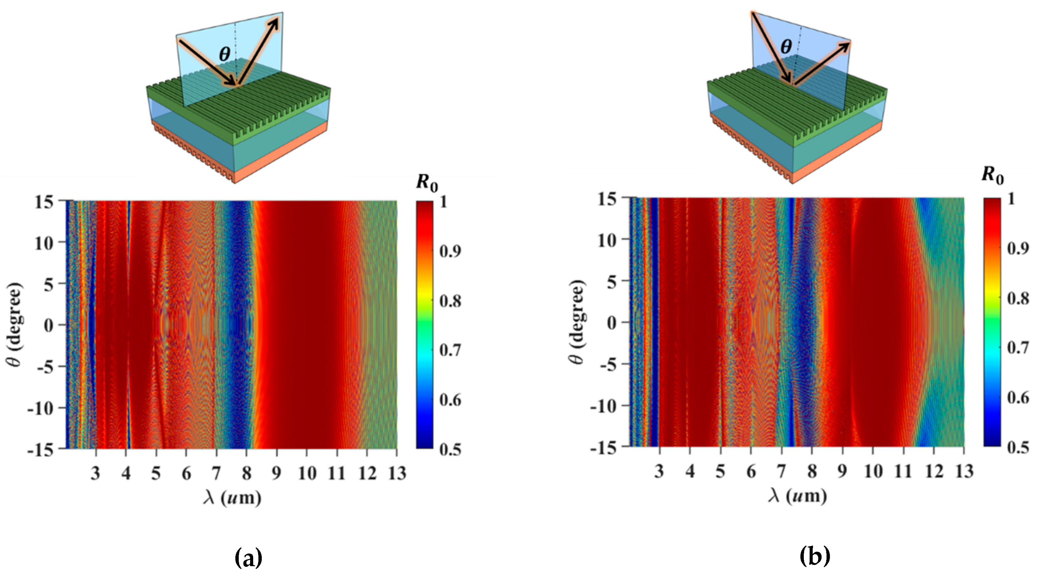
To investigate the angular tolerance of the double-sided metasurface, we examine the dual-band reflection while varying two different angles. Figure 5a illustrates angular variation with the plane of incidence (POI) perpendicular to the grating grooves of the first reflector. In this case, the MWIR reflector is subjected to classical mounting while the LWIR reflector experiences fully conical mounting. In general, the classic incidence varies the resonance more since it induces greater deviation of the diffracted waves than conic incidence [21]. Likewise, as shown in the color map, it is observed that the MWIR reflection band is split under classic mounting but the LWIR reflection band remains robust under fully conical mounting. When the POI is parallel to the grooves, as seen in Figure 5b, the first reflector undergoes fully conical mounting, thereby enhancing angular tolerance in the MWIR band. However, reflectance is somewhat degraded in the LWIR band due to the classical mounting of the second reflector for this case.
5. Conclusions
In summary, we have introduced a dual-band reflector that incorporates double-sided metasurfaces. This innovative design pertains to the cooperation of two GMR reflectors, where two metasurface are combined with an interlayer positioned between them. The top and bottom metasurfaces can be independently designed to achieve the desired spectral response and both functionalities are integrated into a single device with a transparent interlayer. For the MWIR and LWIR reflection bands, two 1D ZCG structures are optimized by utilizing Ge grating layers on a KBr substrate. The Ge/KBr/Ge design demonstrates wideband reflection from 3.3 to 4.77 μm (MWIR region) and 8.85 to 11 μm (LWIR region). In addition, we provide an analytical formula, which will be useful to estimate output spectral response of double-sided metasurfaces in this device class.
Physical construction of the proposed device is challenging due to the necessity of protecting one surface during the pattering of the other. Nevertheless, fabrication is feasible with careful processing and procedures. Alternate implementation is serial arrangement of individual resonators on separate substrates; corresponding devices have not yet been designed. The basic concept of dual reflection band operation is extendable to other spectral regions spanning 400-6000 nm wherein the material selection limitation is not as extreme as in the LWIR band. For polarization independence, the GMR resonators may be patterned as 2D metastructures.
Author Contributions
Conceptualization, Y.K. and R.M.; methodology, Y.K. and R.M.; formal analysis, Y.K; investigation, Y.K. and R.M.; resources, Y.K. and R.M.; writing—original draft preparation, Y.K.; writing—review and editing, R.M.; visualization, Y.K.; supervision, R.M.; project administration, R.M.; funding acquisition, R.M. All authors have read and agreed to the published version of the manuscript.
Funding
This research was supported, in part, by the UT System Texas Nanoelectronics Research Superiority Award funded by the State of Texas Emerging Technology Fund and by the Texas Instruments Distinguished University Chair in Nanoelectronics endowment.
Institutional Review Board Statement
Not applicable.
Informed Consent Statement
Not applicable. Written informed consent for publication must be obtained from participating patients who can be identified (including by the patients themselves). Please state “Written informed consent has been obtained from the patient(s) to publish this paper” if applicable.
Data Availability Statement
The data underlying the results presented in this paper are not publicly available at this time but may be obtained from the authors upon reasonable request.
Acknowledgments
We thank Pawarat Bootpakdeetam for collecting the experimental data in Figure 4a.
Conflicts of Interest
The authors declare no conflicts of interest. The authors declare that they have no known competing financial interest or personal relationships that could have appeared to influence the work reported in this paper.
References
- Morris, N.J.W.; Avidan, S.; Matusik, W.; Pfister, H. Statistics of Infrared Images. Proc. 2007 IEEE Conference on Computer Vision and Pattern Recognition 2007, TR2007-020. [Google Scholar]
- Neinavaz, E.; Schlerf, M.; Darvishzadeh, R.; Gerhards, M.; Skidmore, A. K. Thermal Infrared Remote Sensing of Vegetation: Current Status and Perspectives. Int. J. Appl. Earth Obs. Geoinf. 2021, 102, 102415. [Google Scholar] [CrossRef]
- Siciliani de Cumis, M.; Viciani, S.; Borri, S.; Patimisco, P.; Sampaolo, A.; Scamarcio, G.; De Natale, P.; D'Amato, Spagnolo, V. Widely-Tunable Mid-Infrared Fiber-Coupled Quartz-Enhanced Photoacoustic Sensor for environmental Monitoring. Opt. Express 2014, 17, 22. [Google Scholar] [CrossRef] [PubMed]
- Huang, L.; Han, Z.; Wirth-Singh, A.; Saragadam, V.; Mukherjee., S.; Fröch, J. E.; Tanguy, Q. A. A.; Rollag, J.; Gibson, R.; Hendrickson, J. R.; Hon, P. W. C.; Kigner, O.; Coppens, Z.; Böhringer, K. F.; Veeraraghavan, A. Broadband Thermal Imaging Using Meta-Optics. Nat. Commun. 2024, 15, 1662. [Google Scholar] [CrossRef]
- Shi, X.; Hou, E.; Liang, Z.; Zhang, S.; Dai, R.; Xin, W.; Meng, D.; Liu, H.; Xu, H.; Liu, Y. Broadband Metamaterial Absorber Based on Hybrid Multi-Mode Resonance in Mid-Wave and Long-Wave Infrared Region. Res. Phys. 2022, 42, 105972. [Google Scholar] [CrossRef]
- Zhou, X.; Huang, J.; Wang, H.; Kong, J.; Li, J.; Mu, Y.; Zhang, Y.; Ma, W.; Ren, H.; Li, D.; Jiang, Z.; Sun, H.; Zhao, C. Dual-band MWIR/LWIR Superlattice Infrared Focal Plane Arrays for Simultaneous Detection. Infrared Phys. Technol. 2023, 128, 104539. [Google Scholar] [CrossRef]
- Gambino, F.; Giaquinto, M.; Ricciardi, A.; Cusano, A. (INVITED)A Review on Dielectric Resonant Gratings: Mitigation of Finite Size and Gaussian Beam Size Effects,". Results Opt. 2022, 6, 100210. [Google Scholar] [CrossRef]
- Ji, W.; Chang, J.; Xu, H. X.; Gao, J. R.; Gröblacher, S.; Urbach H., P.; Adam, A. J. L. Recent Advances in Metasurface Design and Quantum Optics Applications with Machine Learning, Physics-Informed Neural Networks, and Topology Optimization Methods. Light Sci. Appl. 2023, 12, 169. [Google Scholar] [CrossRef] [PubMed]
- Ferraro, A.; Zografopoulos, D. C.; Caputo, R. Guided-Mode Resonant Narrowband Terahertz Filtering by Periodic Metallic Stripe and Patch Arrays on Cyclo-olefin Substrates. Sci. Rep 2018, 8, 17272. [Google Scholar] [CrossRef] [PubMed]
- Ko Y., H.; Magnusson, R. Wideband Dielectric Metamaterial Reflectors: Mie Scattering or Leaky Bloch Mode Resonance? Optica 2018, 5, 289. [Google Scholar] [CrossRef]
- Hu, Y.; Wang, X.; Luo, X.; Ou, X.; Li, L.; Chen, Y.; Ping, Y.; Wang, S.; Duan, H. All-Dielectric Metasurfaces for Polarization Manipulation: Principles and Emerging Applications. Nanophotonics 2020, 9, 3755. [Google Scholar] [CrossRef]
- Simlan, F. A.; Lee, K. J.; Ko, Y. H.; Gupta, N.; Magnusson, R. Fabrication of Single-Layer Resonant Infrared Filters with High Optical Density. J. Lightwave Tech. 2024, 42, 2345. [Google Scholar] [CrossRef]
- Shokooh-Saremi, M.; Magnusson, R. Particle Swarm Optimization and Its Application to the Design of Diffraction Grating Filters,". Opt. Lett. 2007, 32, 894. [Google Scholar] [CrossRef] [PubMed]
- Moharam, M. G.; Grann, Eric B.; Pommet, Drew A.; Gaylord, T. K. Formulation for Stable and Efficient Implementation of the Rigorous Coupled-Wave Analysis of Binary Gratings. J. Opt. Soc. Am. A 1995, 12, 1068. [Google Scholar] [CrossRef]
- RSoft Products, DiffractMod, Synopsys, Inc. (2024). 2024.
- Magnusson, R. Wideband Reflectors with Zero-Contrast Gratings. Opt. Lett 2014, 39, 4337. [Google Scholar] [CrossRef] [PubMed]
- Magnusson, R.; Shokooh-Saremi, M. Physical Basis for Wideband Resonant Reflectors. Opt. Express 2008, 16, 3456. [Google Scholar] [CrossRef] [PubMed]
- Kaiser, W.; Spitzer, W. G.; Kaiser, R. H.; Howarth, L. E. Infrared Properties of CaF2, SrF2, and BaF2. Phys. Rev. 1962, 127, 1950. [Google Scholar] [CrossRef]
- Li. H., H. Refractive Index of Alkali Halides and Its Wavelength and Temperature Derivatives. J. Phys. Chem. Ref. Data 1976, 5, 329. [Google Scholar] [CrossRef]
- Li. H., H. Refractive Index of Silicon and Germanium and Its Wavelength and Temperature Derivatives,". J. Phys. Chem. Ref. Data 1980, 9, 561. [Google Scholar] [CrossRef]
- Ko, Y. H.; Niraula, M.; Lee, K. J.; Magnusson, R. Properties of Wideband Resonant Reflectors under Fully Conical Light Incidence. Opt. Express 2016, 24, 4542. [Google Scholar] [CrossRef] [PubMed]
Figure 1.
Concept of a double-sided metasurface fashioning a dual-band reflector in air. Cooperative interaction between (i) MWIR and (ii) LWIR reflectors enables dual bands of high reflection as presented in (iii).
Figure 1.
Concept of a double-sided metasurface fashioning a dual-band reflector in air. Cooperative interaction between (i) MWIR and (ii) LWIR reflectors enables dual bands of high reflection as presented in (iii).
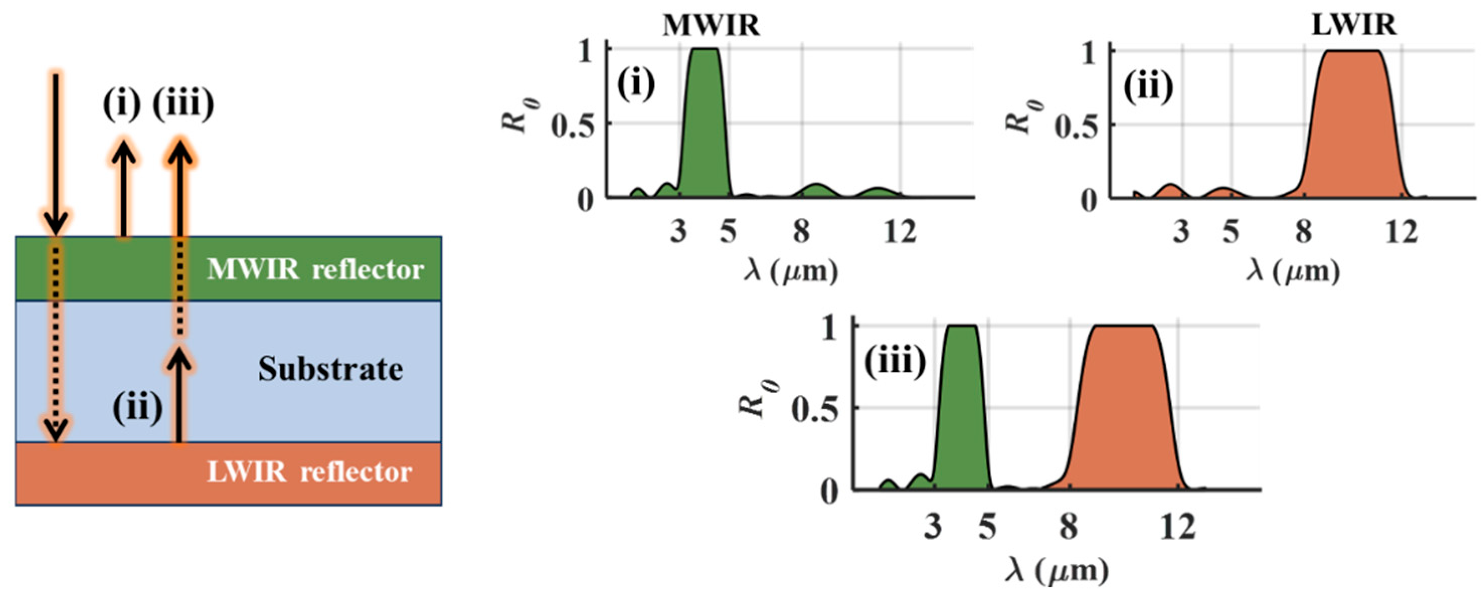
Figure 2.
Modelling of a double-side metasurface for the dual-band reflector. The (a) first and (b) second metasurface for each MWIR and LWIR reflector designed by a resonant 1D grating structure. The grating parameters includes a period (), fill factor (), grating depth () and sublayer thickness (). The and indicate high refractive index of grating layer and low refractive index of substrate. (c) The double-sided metasurface composed of each MWIR and LWIR reflector with a thick interlayer of substrate (d). In the simulated R0 spectrum, both MWIR and LWIR reflection bands are clearly observed.
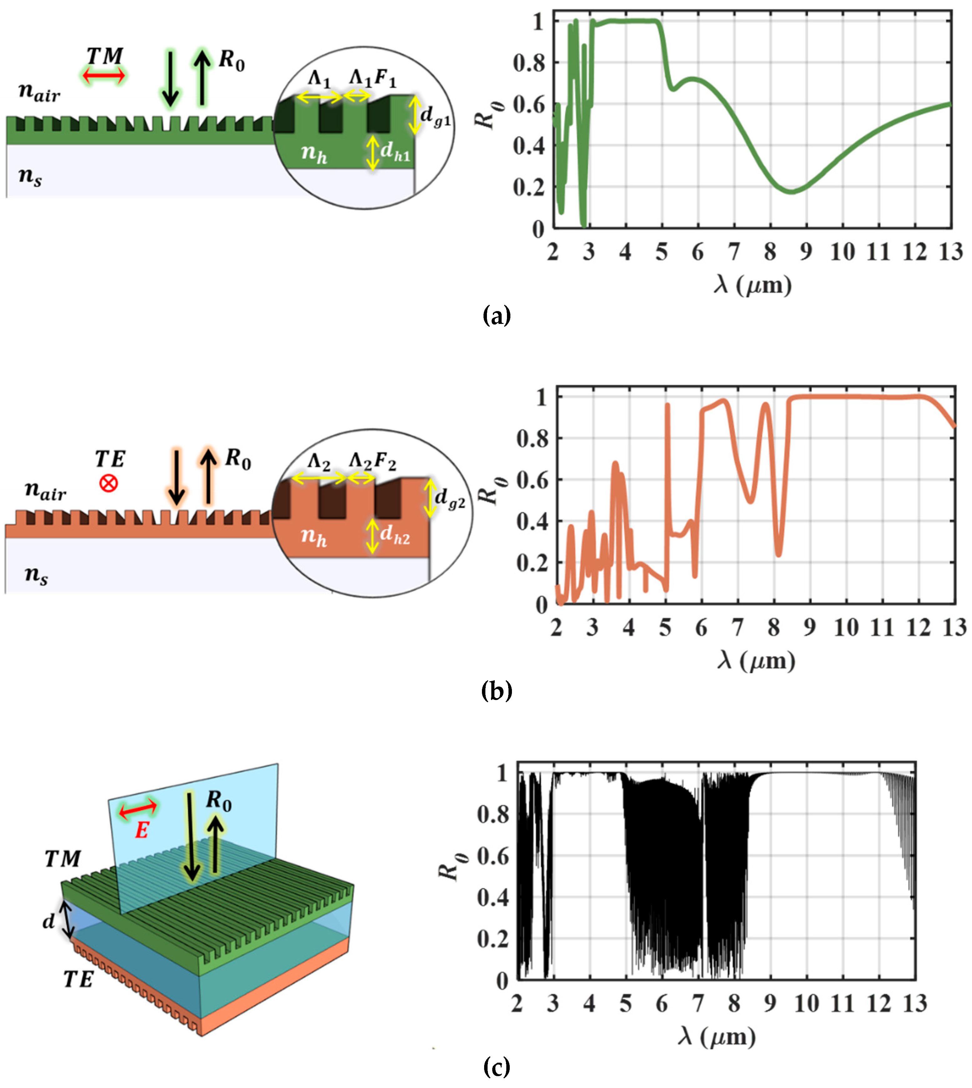
Figure 3.
Analytical modelling for the double-sided metasurface in lossless and lossy materials. (a) Schematic for total reflection between two interfaces separated by a distance (d) where the R1 and R2 are reflectance at the first and second interface respectively. The absorption coefficient (α) is obtained by where the k is an extinction coefficient of the interlayer. (b) Calculation results from solving (3) for k=0 (blue bold line) and 0.001 (red bold line) with d=1 mm. The R1 and R2 are the zeroth order reflectance of MWIR and LWIR reflector in Figures 2a and 2b. For comparison, the numerical simulation results are also added for k=0.001. The thin red and green lines represent absorption (A) and R0 spectrum.
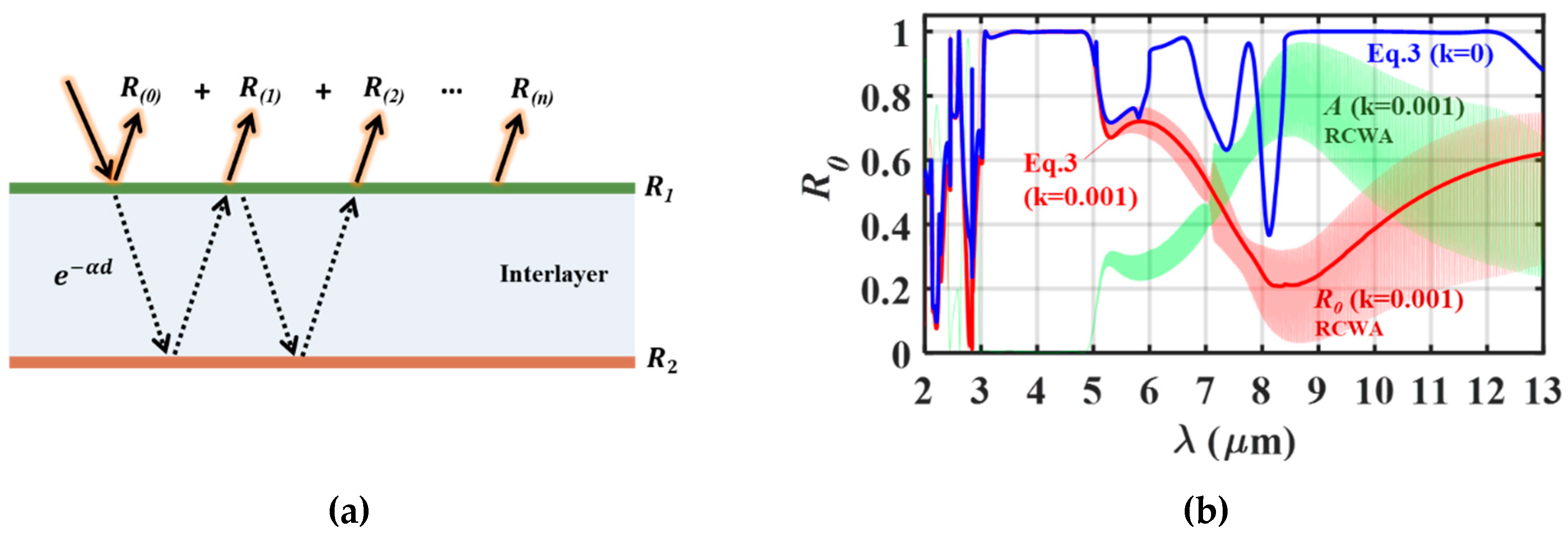
Figure 4.
Effects of interlayer on the double-sided metasurface. (a) Zeroth order transmittance (T0) spectra of 1 mm-thick-substrate as the interlayer. The T0 spectra of CaF2 (blue line) and KBr (green line) substrates are simulated by RCWA. Additionally, the measured T0 spectrum of the CaF2 substrate is also compared to simulation result. (b) Design and simulation results of double-sided metasurface based on Ge/CaF2/Ge material system where the top and bottom grating parameter sets are { = 1.725 μm, =0.732, =0.9 μm, =0.49 μm} and {= 6 μm, =0.38, =1.7 μm, =0.32 μm}. Due to the absorption at longer wavelengths, the LWIR reflection is degraded. (c) Design and simulation results of double-sided metasurface based on Ge/KBr/Ge materials. The top and bottom grating parameter sets are {= 1.73 μm, =0.73, =0.92 μm, =0.5 μm} and {= 5.39 μm, =0.38, =1.75 μm, =0.34 μm}.
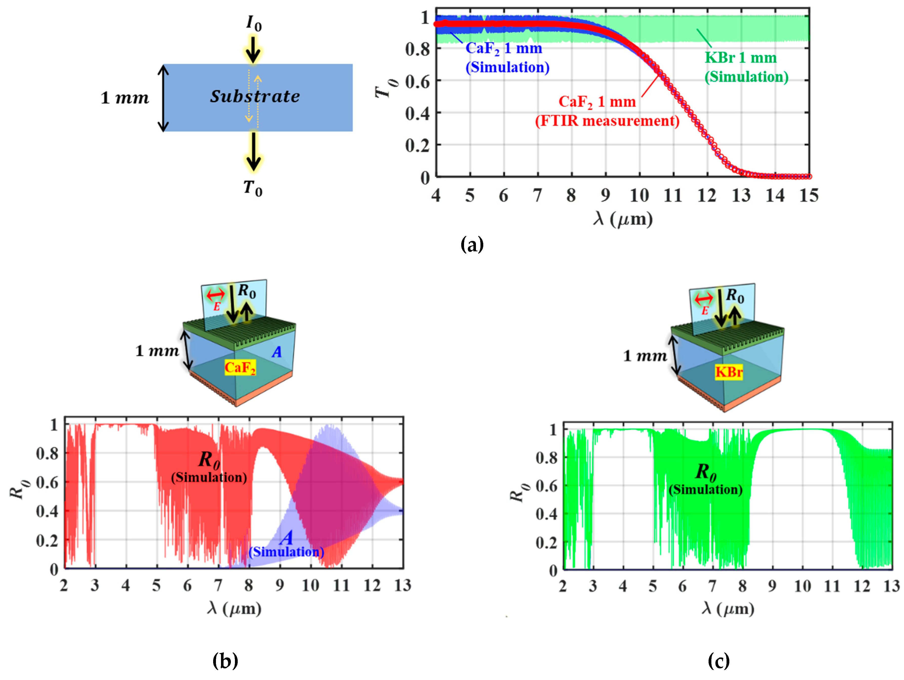
Figure 5.
Angular tolerance of the double-sided metasurface. Simulated maps for the different angle of incidence () as the plane of incidence (POI) is (a) parallel and (b) perpendicular to the grating groove of the first reflector.}.
Figure 5.
Angular tolerance of the double-sided metasurface. Simulated maps for the different angle of incidence () as the plane of incidence (POI) is (a) parallel and (b) perpendicular to the grating groove of the first reflector.}.
Disclaimer/Publisher’s Note: The statements, opinions and data contained in all publications are solely those of the individual author(s) and contributor(s) and not of MDPI and/or the editor(s). MDPI and/or the editor(s) disclaim responsibility for any injury to people or property resulting from any ideas, methods, instructions or products referred to in the content. |
© 2024 by the authors. Licensee MDPI, Basel, Switzerland. This article is an open access article distributed under the terms and conditions of the Creative Commons Attribution (CC BY) license (http://creativecommons.org/licenses/by/4.0/).
Copyright: This open access article is published under a Creative Commons CC BY 4.0 license, which permit the free download, distribution, and reuse, provided that the author and preprint are cited in any reuse.


