1. Introduction
The industrial and innovative development of the country is unthinkable without the development of tool production, because it is closely related to mechanical engineering and the metalworking industry.
The processing of holes, which are subject to high demands on the accuracy of size, shape and location, is one of the areas of development of the metalworking industry.
Investments in advanced tooling and cutting-edge technology with the specific goal of reducing the machining time required for holes with tight tolerance and lowering tool wear rates at a reduced cost will be closely scrutinized and highly regarded within the machining sector [1, 2].
The most widely used method for creating holes in solid materials is through the process of drilling. This machining method takes place under challenging cutting conditions, such as: chip removal and supply of cutting fluid are difficult; a high friction between the chips and the grooves of the drill, on one hand, and between the chips and the machined surface, on the other hand; a continuous variation of the cutting speed (from maximum to zero). occurs along the cutting edge by moving from the outer diameter towards the center; the main relief angle α is variable, increasing as the measuring point approaches the center of the tool; the rake angle on the transverse edge is very unfavorable. For standard twist drills, the rake angle γ at the transverse edge is up to minus 57° – 60°. Because of this, on the transverse edge, instead of cutting, there is crushing, extrusion and scraping of the metal. In a traditional twist drill, the rake angle is different at different points of the cutting blade during machining. The cutting speed is not constant and varies from zero in the center of the drill to a certain maximum value at the periphery of the drill. In the center of the hole, under the transverse edge of the drill, there is no cutting as such; the material being processed is crushed, extruded and scraped towards the periphery under the cutting edges, thereby increasing the temperature, deteriorating the quality of processing, and creating unfavorable cutting conditions. A feature of the drill geometry and its disadvantage is the presence of a transverse conditionally cutting edge [3, 4].
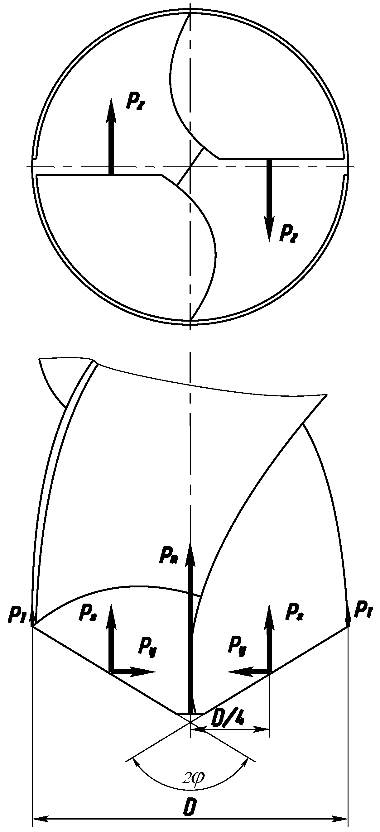
When drilling, the resultant cutting forces applied to the cutting edges of the drill, as usual, are decomposed into three mutually perpendicular force components (
Figure 1):
- -
along the drill axis – axial forces Рх;
- -
tangents to the drill circumference, that is in the direction of the cutting speed - tangential forces Рz;
- -
along the drill radius – radial forces Ру.
The axial force Рх overcomes the material's resistance to drill penetration and accounts for about 40% of the total axial force. Tangential forces arise due to the resistance of the workpiece material to separation of the cut layer and creates a torque on the drill. The radial forces on the two cutting edges are directed in opposite directions and are mutually balanced if they are equal in magnitude, otherwise they contribute to the retraction of the drill. In addition, the drill is subject to resistance forces arising at the transverse cutting edge Рп, which constitute 57% of the axial force, and according to G.N. Sakharov up to 65%, and friction forces on ribbons РТ – 3%.
To improve cutting conditions, methods have been developed for sharpening standard drills and sharpening the transverse edge, as well as their new, more advanced designs [
5,
6,
7,
8]. According to Zhirov [
9], to reduce the axial force when drilling, the transverse edge is cut by a groove, remaining on the drill, but it in a modified form, with smaller rake angles. Thus, a rake angle is created on each of the two halves of the transverse edges (γ=0˚). These drills have demonstrated their effectiveness when used for machining cast iron. According to Klemm et al. [
20], an increased durability of drills can be obtained by using a sharpening which provides a transverse edge of 0.1–0.2 mm. For drills equipped with carbide, designs with a special point have been developed: jumperless drill designed by KMG, drill designed by N. A. Shevchenko and drill designed by N. K. Klebanov [
9].
Experimental studies conducted by several authors [10-13] have shown that bridgeless drills with a radial arrangement of the main cutting edges along their entire length or on part of the length of the edges adjacent to the center of the drill provide the best results in terms of productivity, reduction of axial force on the transverse edge, and wear of the drill. Nevertheless, on these drills the transverse edge is not fully removed and instead remains in a slightly modified form. Furthermore, the forces acting on the transverse edge are not eliminated and the rake angle at the transverse edge decreases, but the negativity persists. The above-mentioned operating conditions of the transverse edge greatly compromise both the processing conditions and the quality of the machined hole.
With this goal in mind, a new twist drill design was proposed to eliminate the transverse edge. Therefore, a new metal-cutting tool was designed - a double-edge spiral drill without a transverse edge [
14,
15]. Removing the transverse edge on the drill can significantly minimize heat and wear during cutting, leading to enhanced durability of the drills.
2. Materials and Methods
When processing holes with a double-edge spiral drill without a transverse edge, in which the source of the destabilizing influence – the high heating zone – is eliminated, the cutting and shaping conditions of the machined surface are improved, and the roughness is significantly reduced. The geometric parameters of the new cross-edge twist drill correspond to the fundamental principles of the cutting theory of the cutting wedge. When using a new cutting tool, the cutting conditions change: the layer of metal being cut with the thickness of the cut а, unlike processing with a traditional drill, it is divided into two parts by a cut groove. Instead of a transverse edge on a traditional drill, the new drill has cutting edges whose angles correspond to the fundamental principles of cutting theory about a cutting wedge. When changing the type of cutting tool, the processing method and cutting conditions change, the source of increased heat generation is eliminated and the quality of processing improves.
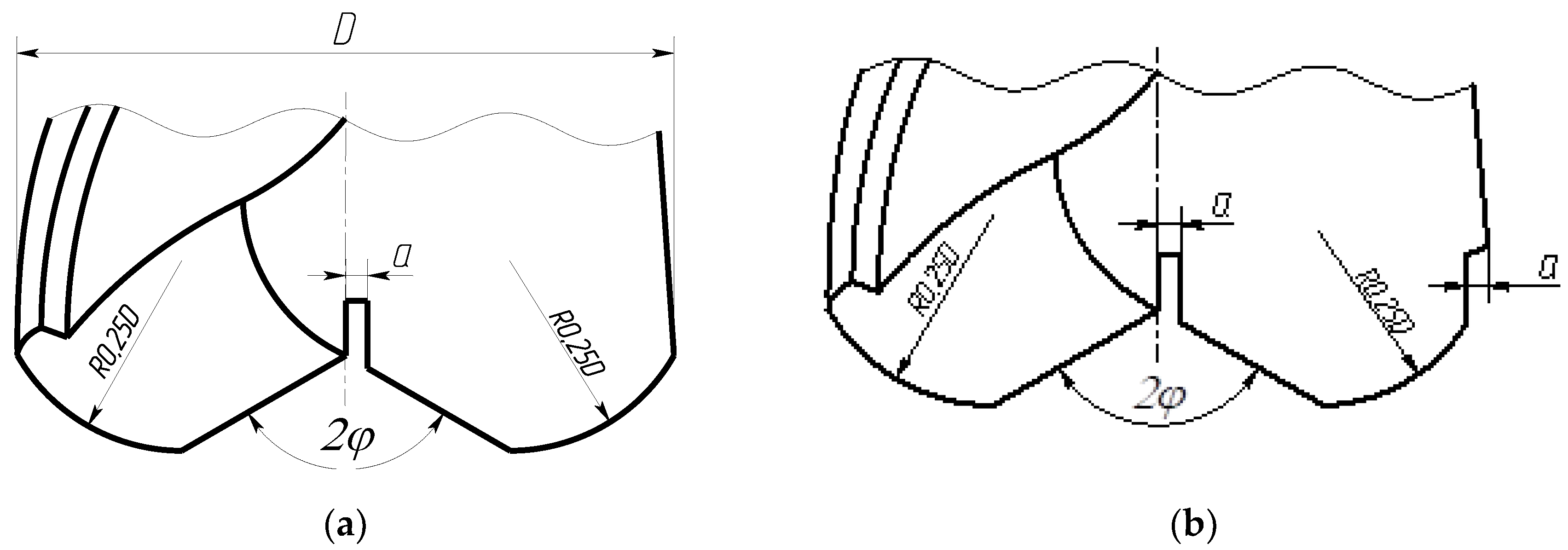
A double-edged twist drill without a transverse edge has design elements that coincide with the elements of a conventional drill: a shank, a neck, two spiral grooves for chip removal, a working part (including the calibrating and cutting zones), a core diameter, a band on the calibrating part. Design features that distinguish it from its analogue include a cut of the drill tip in a section of half the diameter in the axial part at an angle (directed towards the shank) corresponding to the tip angle (the known range of the tip angle is 30° - 150°). This forms two tips and four main cutting edges - two external (on the periphery of the drill) and two internal (on the tip cut section), separated by a groove offset relative to the drill axis. One of the walls of this groove is located on the axis, allowing the drill to cut off the internal cavity that prevents cutting. Both ends of the drill are located on the same line, perpendicular to the axis, and in the same axial plane; the main internal cutting edges also lie in the same axial plane, excluding the transverse edge, which is present in all conventional drills and creates unfavorable cutting conditions. The drill also has a smoothing (guide) tape on the back side of each blade. The design includes versions for both right and left cutting.
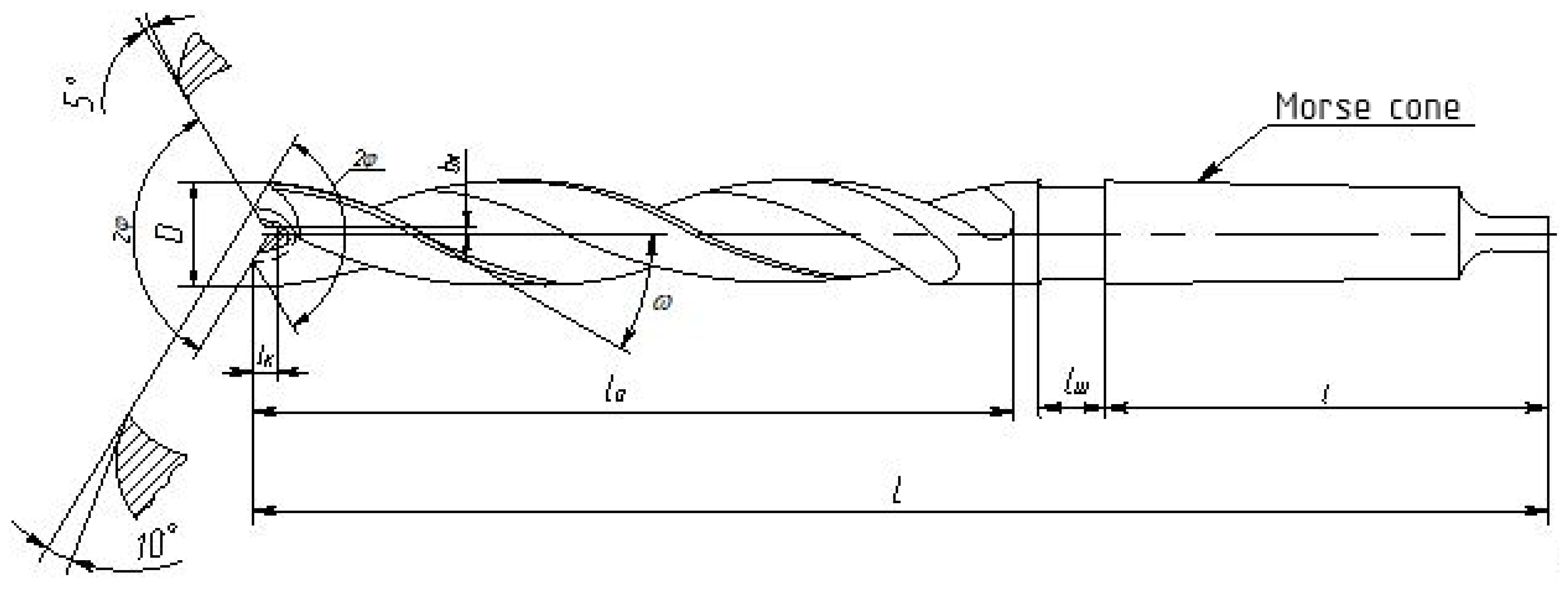
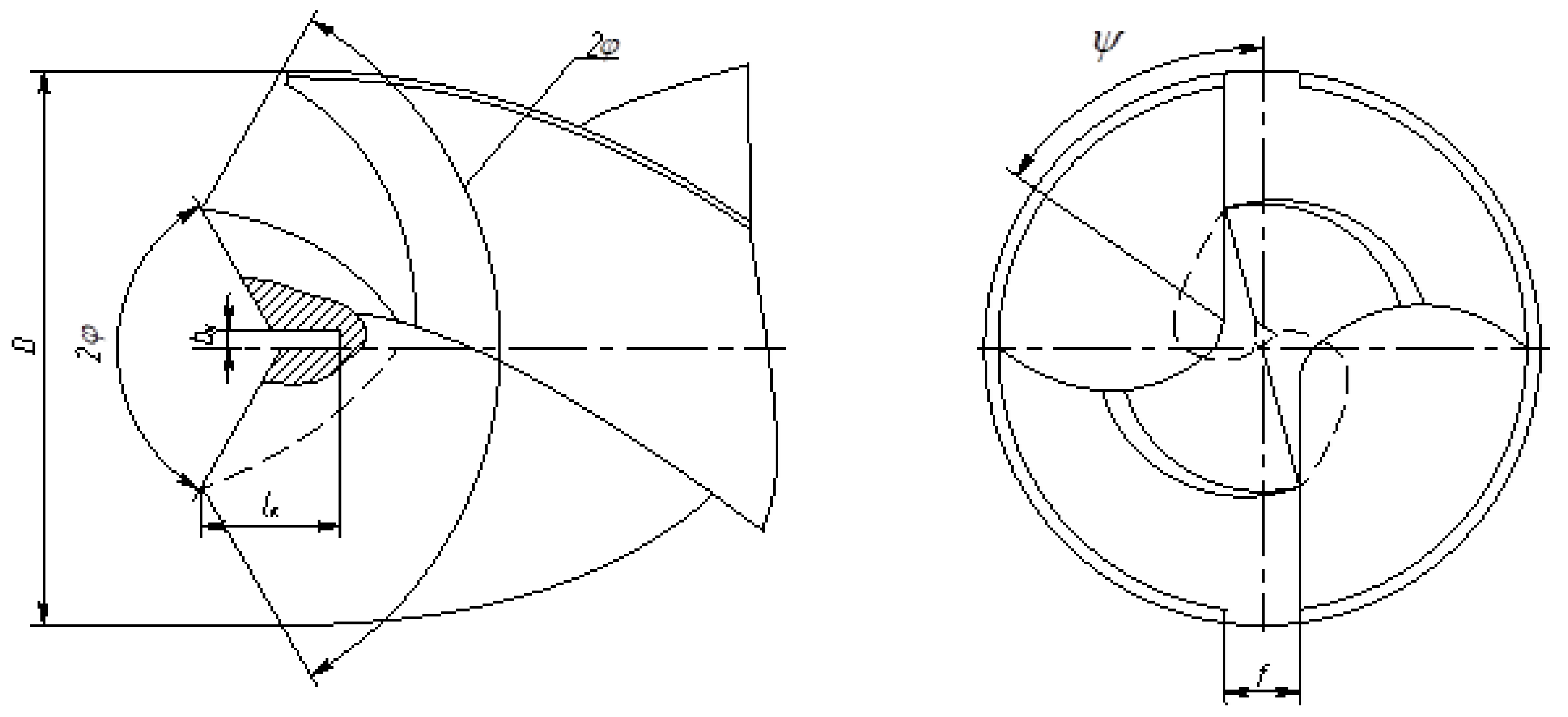
The main elements and dimensions are shown in
Figure 2 and
Figure 3: angle 2φ at the apex on the periphery and 2φ (angle directed to the shank) on the cut of the front axial part; 1 — working part of the drill with helical chip flutes
; ω — angle of inclination of the helical flute; 2 — neck; 3 — tapered shank with Morse taper; 4 — foot; a — cut thickness;
— length of outer cutting edges with an angle of 2φ at the top;
— length of unshortened inner cutting edge with a reverse angle of 2φ at the top;
(where S
o – axial feed per drill revolution) — length of cutting edges at half the axial feed (as with traditional drills). To prevent displacement of the drill axis and the hole due to the asymmetry of the cutting edges (
), guide and smoothing strips 15 are made on the drill feathers near the chip grooves; the reverse cutting edge of normal length ensures complete removal of chips to the axis of the hole being machined.
In
Figure 3 on the right projection, the marks from the point of the front surface on the chip flute of the drill are conventionally shown by a dashed line. The transverse edge of the specified drill is cut off, a groove is cut, one wall of which coincides with the axis or is slightly offset relative to the axis. This will eliminate the force arising on the transverse edge of a standard drill, and improve the force relations in the cutting zone, reduce heat generation, and improve the quality of processing (
Figure 4).
The recommended dimensions of the groove to be cut depending on the diameter of the drill are presented in the
Table 1, and in the
Table 2 – recommended sharpening angles. The angle of inclination of the separating groove
ψ is recommended to be within 45° – 50°.
The main distinguishing feature of the method of drilling holes with a double-edge twist drill without a transverse edge is the absence of a transverse edge and its replacement with internal cutting blades in compliance with the fundamental provisions on the geometry of the cutting edge with positive front and back angles.
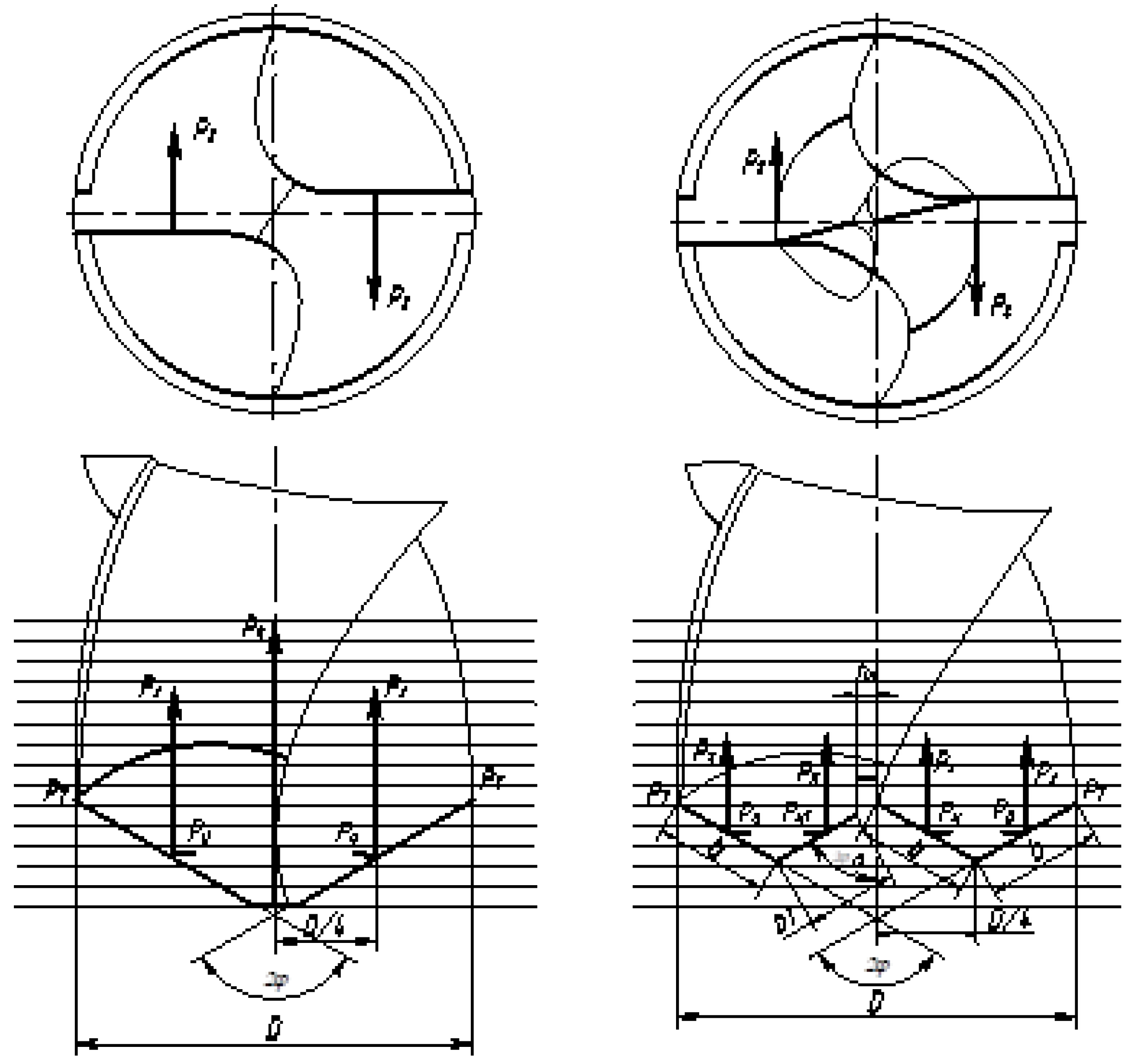
Figure 4 shows a diagram of the forces acting on a double-edge twist drill without a cross edge: P
ao – component of the axial force acting on the outer cutting edges; P
ai - components of the axial force acting on the internal cutting edges, P
aΣ – the total component of the axial forces acting on the cutting edges; P
ro – radial force acting on the outer cutting edges; P
rΣ – total radial cutting force; at the outer edges the radial forces are balanced; P
rfli – radial cutting force on full length inner cutting edge; P
rice – radial cutting force on the inner cutting edge shortened by cutting a groove; в – groove width; cutting edge shortening
ΔК.
At length
ΔК the radial cutting force is not balanced, which may cause the hole to break apart in diameter [
18]. To prevent breakage in mass and large-scale production, it is necessary to apply processing using jig bushings.
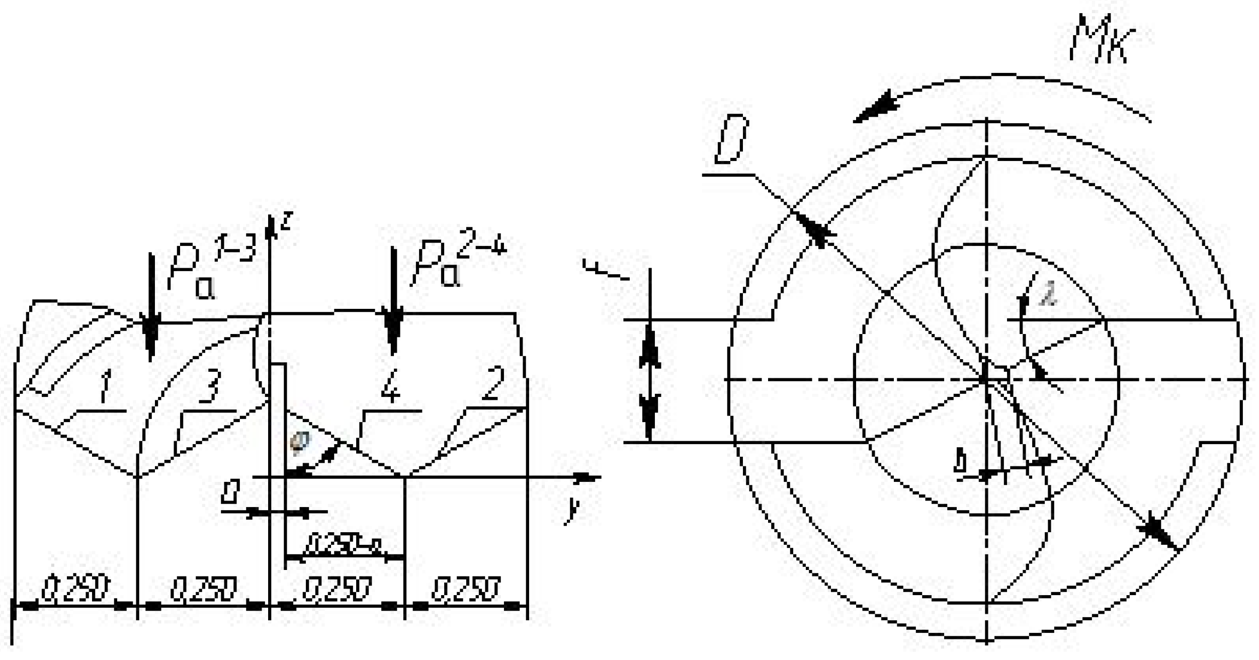
Figure 5 shows a diagram of drilling a hole with a double-vertex drill without a transverse edge and the dimensions are equal to a quarter of the diameter (0,25D), into which the diameter of the drill is divided by two formed vertices, corresponding to the lengths of the formed cutting edges 1, 2, 3, 4.
Axial force
, acting on a drill without a transverse edge, consists of two forces acting on each drill blade:
where
– component of the axial force acting on the drill blade with edges
1-
3;
– component of the axial force acting on the drill blade with edges 2-4.
To assess the degree of equilibrium of forces acting on the cutting edges of a double-edge spiral drill without a transverse edge, we introduce concepts and notations for specific forces acting per unit length of the cutting edges.
– specific axial force acting per unit of projected length of the cutting edge in a plane perpendicular to the drill axis.
It should be borne in mind that cutting edges of the same length are equally loaded, and the projected length of the cutting edge makes it possible to conveniently evaluate forces without considering the angle of inclination of the cutting edges, using the principle of proportionality of lengths.
In
Figure 5, the total axial force on a drill without a transverse edge
where
– axial force acting when drilling on a cross-edge drill. The axial force is determined by the well-known formula:
Then for the axial force acting on a drill without a transverse edge, the formula takes the form:
To determine the equilibrium conditions for the cutting part of a drill without a transverse edge, we present an analysis of the axial forces acting on the cutting edges of the drill. To do this, we first define:
1 The specific component of the axial cutting force per unit length of the drill diameter (projected cutting edge ), as stated above;
2 Specific component of the axial cutting force per unit length of the cutting edges of the drill
along its diameter in the direction of the axis
Y considering the angle of inclination of the cutting edges
φ and
λ in
Figure 5.
1 Total projected length of drill cutting edges without transverse edge:
2 The total length of the cutting edges of the drill without the transverse edge:
Specific axial force per unit length of the cutting edge:
In the expression for the specific axial force for the selected cutting conditions (one material, a given diameter), the variable that influences the change in the specific cutting force for drawing up a mathematical model will be only the feed; therefore, the specific value of the cutting force will take the form:
1 In the first case:
where
;
2 In the second case:
where
1 Expression for the axial forces of a double-edge twist drill without a transverse edge acting on a blade with cutting edges
1 и
3:
where
2 Expression for the axial forces of a double-edge twist drill without a transverse edge acting on a blade with cutting edges
2 и
4:
where
Thus, the feathers of a double-edge twist drill without a transverse edge are subject to forces that are not equal to each other:
The difference in axial forces creates a bending moment at the tops of the cutting part of the drill, which contributes to the withdrawal of the drill during drilling. Its magnitude needs to be investigated.
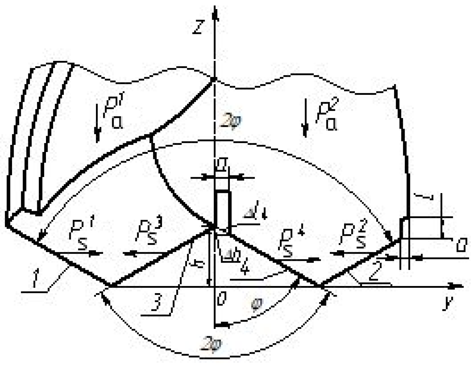
For further analysis, we should also introduce the concept of shear forces in the transverse direction (perpendicular to the drill axis) acting on the cutting edges, and the concept of shear forces and specific shear force acting on the projected length of the cutting edge along the direction of the drill axis (
Figure 6).
Shear forces on the blade of a drill with cutting edges
1 and
3 in
Figure 6:
– shear force acting in the transverse direction on the cutting edge 1 double tip twist drill without cross edge;
– shear force acting in the transverse direction on the cutting edge 3 double tip twist drill without cross edge.
On cutting edges 1 and 3 shear forces of equal magnitude and opposite in direction act, as a result of which the drill blade with cutting edges 1 and 3 is balanced against shear in the transverse direction.
Consider the blade of a double-edge twist drill without a cross edge with cutting edges
2 and
4. In
Figure 5, the cutting edge 4 shortened by cutting a groove width
a along the axis Y
У, one wall of which coincides with the axis of the drill, therefore the shear force on the cutting edge 4 will be reduced by an amount proportional to the width
a grooves, and then:
where
– shear force acting in the transverse direction on the cutting edge 2 double tip twist drill without cross edge.
– shear force acting in the transverse direction on the cutting edge 4 double tip twist drill without cross edge.
The difference between these applied forces will ensure that the drill shifts to the left when working. If necessary, this shear force can be determined based on the value of the calculated specific shear force and measured experimentally (moreover, the width of the cut groove must be chosen as small as possible to reduce the shear force. Its value will be equal to
Thus, the drill pen with cutting edges 2 and 4 not balanced against the shear force resulting from shortening the cutting edge 4.
If we consider the entire drill as a whole, then we can move on to the interaction of all cutting edges in kinematics during drill operation: in
Figure 6 cutting edge
1 and a similar cutting edge
2, located on the periphery of the drill are completely balanced, then that is the shear forces on these cutting edges operating under the same conditions are equal in magnitude and opposite in sign.
The following cutting edges operating under the same conditions are cutting edges 3 and 4. which ensures that the drill shifts to the left when working, which was established above from the condition of unbalance of the pen with the cutting edges 2 and 4.
Figure 7 shows the design of a double-edge twist drill without a transverse edge, free from shear force along the axis
Y: due to shortening of the cutting edge
2 on the periphery with a point by the amount
a.
In this design, the drills are protected from shear forces in the direction of the axis
Y drill feathers are loose:
Further analysis shows (
Figure 8) that when operating a double-pointed drill without a transverse edge, free from shear force along the axis
Y, a torque arises from the action of two unequal tangential forces.
Let's look at
Figure 6, which shows the acting forces on the drill feathers, a diagram of the occurrence of shear forces:
1 – full length outer cutting edge on one drill blade;
3 – internal cutting edge on the same drill blade;
4 – the inner cutting edge on the other drill blade with a slotted groove width a for cutting blind hollows between edges
3 and
4 and division of work of cutting edges
3 and
4;
2 – external cutting edge on a drill blade with a shortened cutting internal edge.
After cutting the cutting edge 4 by cutting a groove width а in the axial part of the drill, the work of the internal cutting edges 3 and 4 unbalanced: to the edge 3 drill, the length of which remains unchanged during the cutting process, due to the shortening of the cutting edge 4, there is a shear force greater than the shear force acting on the cutting edge 4, by an amount proportional to the width of the cut groove a, due to which a shear force is applied to the cutting edge 3. This shear force can only be balanced by a shear force applied to the cutting edge 1 due to the shortening of the cutting-edge opposite to it in terms of the action of forces 2 in figure 7. Let us denote the forces acting on the cutting edges 1, 2, 3, 4 in figure 6: – shear shear force acting on the cutting edge 1; – shear shear force acting on the cutting edge 2; – shear shear force acting on the cutting edge 3; – shear shear force acting on the cutting edge 4.
and , acting on the feathers of a double-edge twist drill without a transverse edge.
By the nature of the work and the action of forces when the cutting edges are equal
1 and
2 shear forces are oppositely directed, equal and balanced:
After cutting a groove between the cutting edges
3 and
4 on the cutting edge
4 the shear force has decreased, due to which the cutting edge
3 is shifted more strongly to the left by the unbalanced part of the force, proportional to the width of the cut groove. Then the cutting edge
3 tries to move a force that is part of the shear force
P
3s, conventionally shown in
Figure 6 as
It is equal to the specific shear force,
operating on the site
, i.e.
.
When using a double-edge twist drill without a cross-edge, shown in
Figure 6, a shear force acts on the cutting part, making it difficult to drill at the beginning of the drill. You can use pre-drilling to a depth equal to half the diameter of the hole to center the drill, and in mass production use jig work. This disadvantage is compensated by easier cutting conditions, increased cutting speed and increased durability of drills without a transverse edge [
19].
Figure 7 shows the design of a double-edge twist drill without a transverse edge with balanced shear forces on both feathers, which is achieved by sharpening the cutting edge
2 by an amount equal to the width of the groove between the cutting edges
3 and
4.
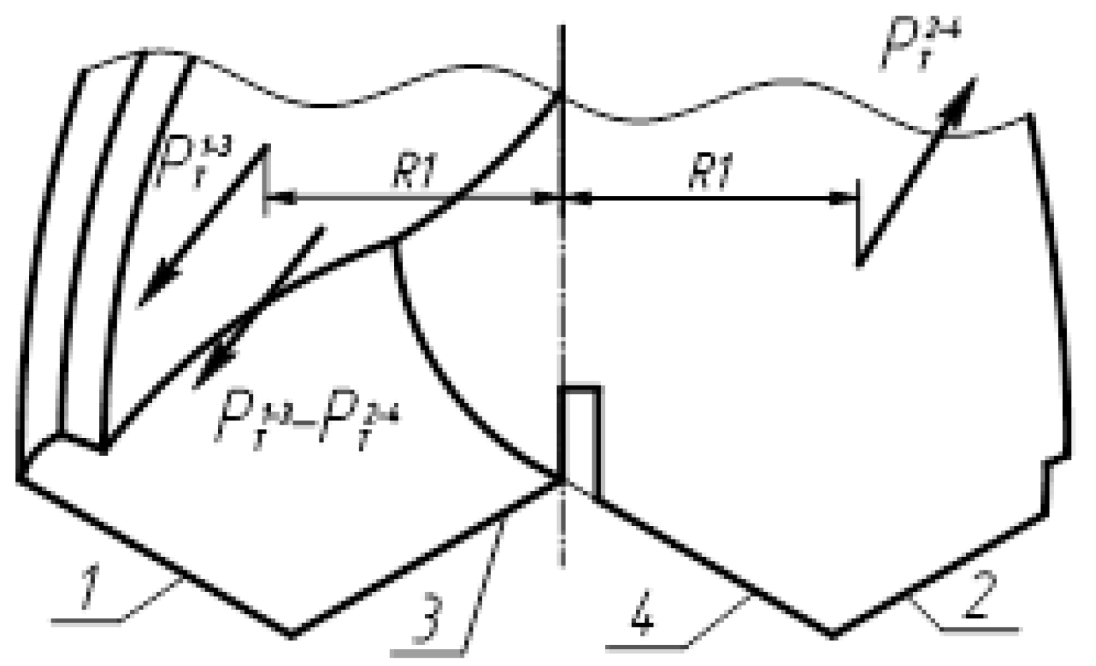
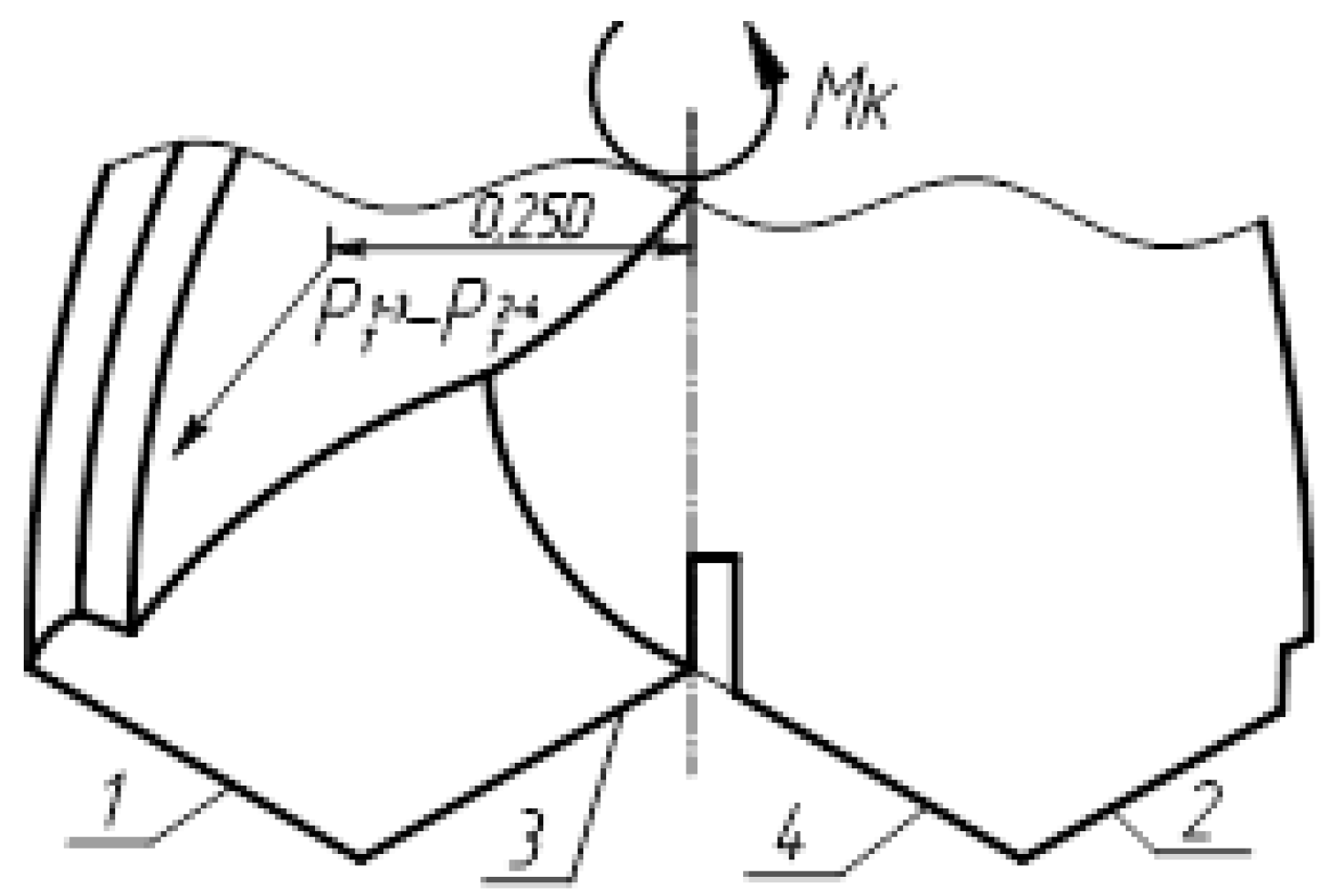
Figure 8 shows tangential forces
and
, acting on the feathers of a double-edge twist drill without a transverse edge and creating a cutting resistance torque, while
, which creates a torque and force equal to the difference in forces:
, acting on a pen with cutting edges
1 and
3 (
Figure 9).
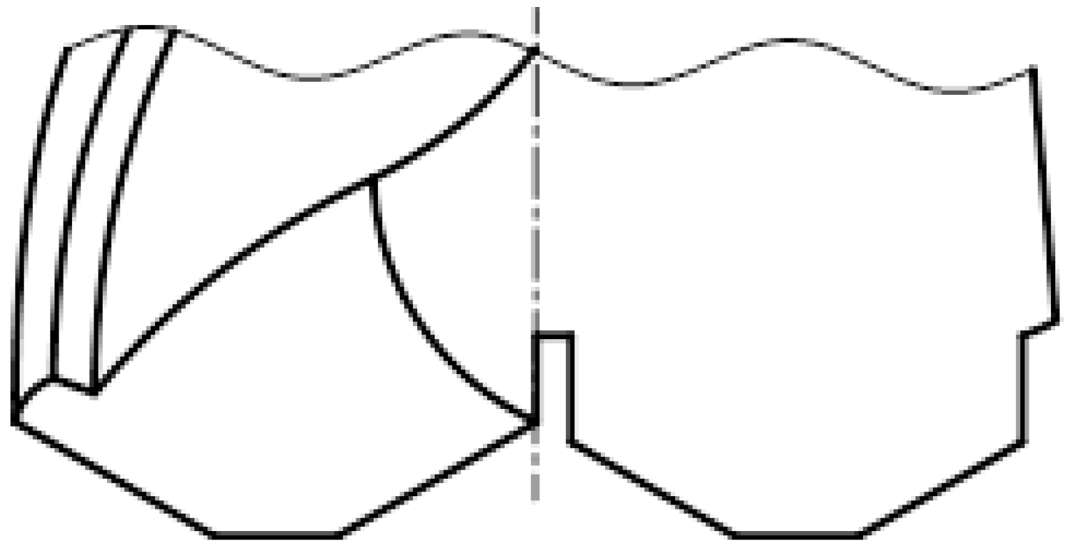
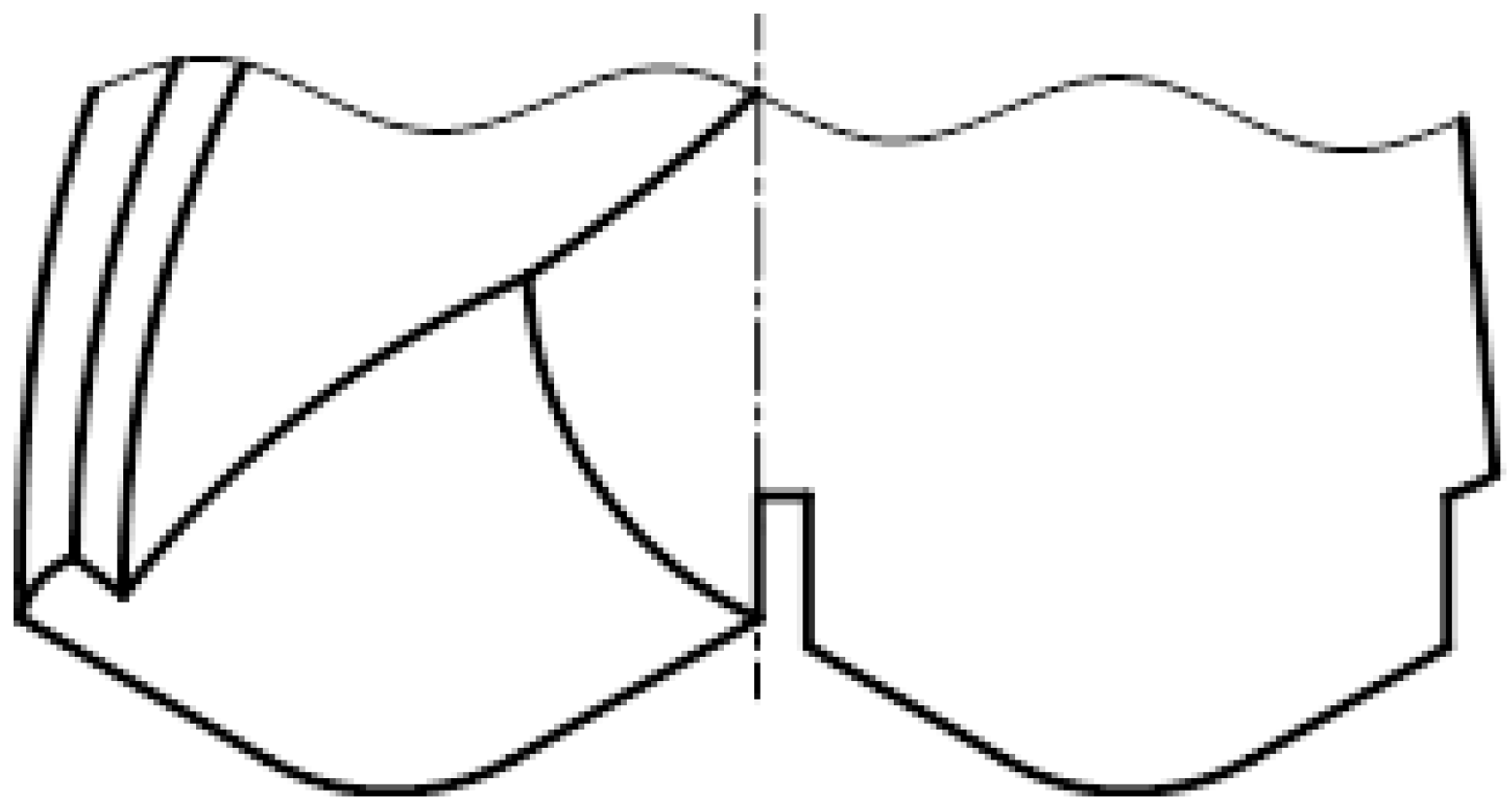
To increase the durability of a double-vertex spiral drill without a transverse edge, it is proposed that the tips of the drill on each blade be cut off (
Figure 10) or rounded along the radius (
Figure 11).
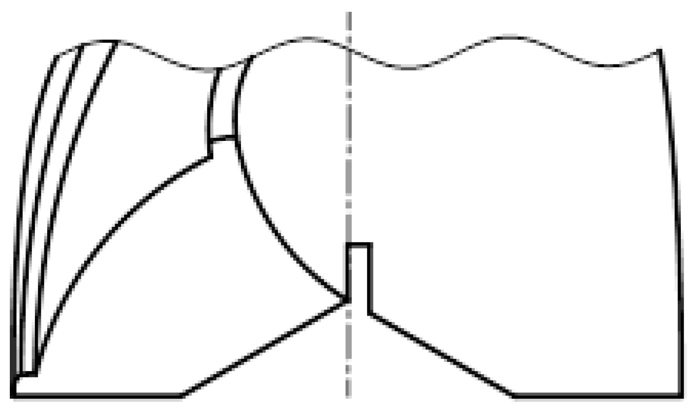
To increase the tool life of a double tip twist drill without a cross edge, the tip angle on the outer cutting edges
1 and
2 can be made equal to 180 degrees (
Figure 12) and with roundings (
Figure 13), and the cutting edges
3 and
4 located along the generatrices of a cone with a reverse angle at the apex.
Similar designs of the cutting part of a double-edge spiral drill without a transverse edge can also be used for a double-edged feather drill without a transverse edge [
15].
3. Experimental Part and Discussion
Prototypes of a double-vertex spiral drill without a transverse edge were manufactured in three standard sizes with diameters of 13.5 mm, 19.5 mm and 29.5 mm at the machine-building enterprise of the city of Pavlodar LLP «Format Mach Company» (former tool plant) and tested in the training and production workshops of the faculty metallurgy, mechanical engineering and transport of Toraigyrov University at the department of «Mechanical Engineering and Standardization» (
Figure 14).
Production tests of prototypes were carried out at LLP «Factory of non-standardized equipment» under the conditions given in
Table 3.
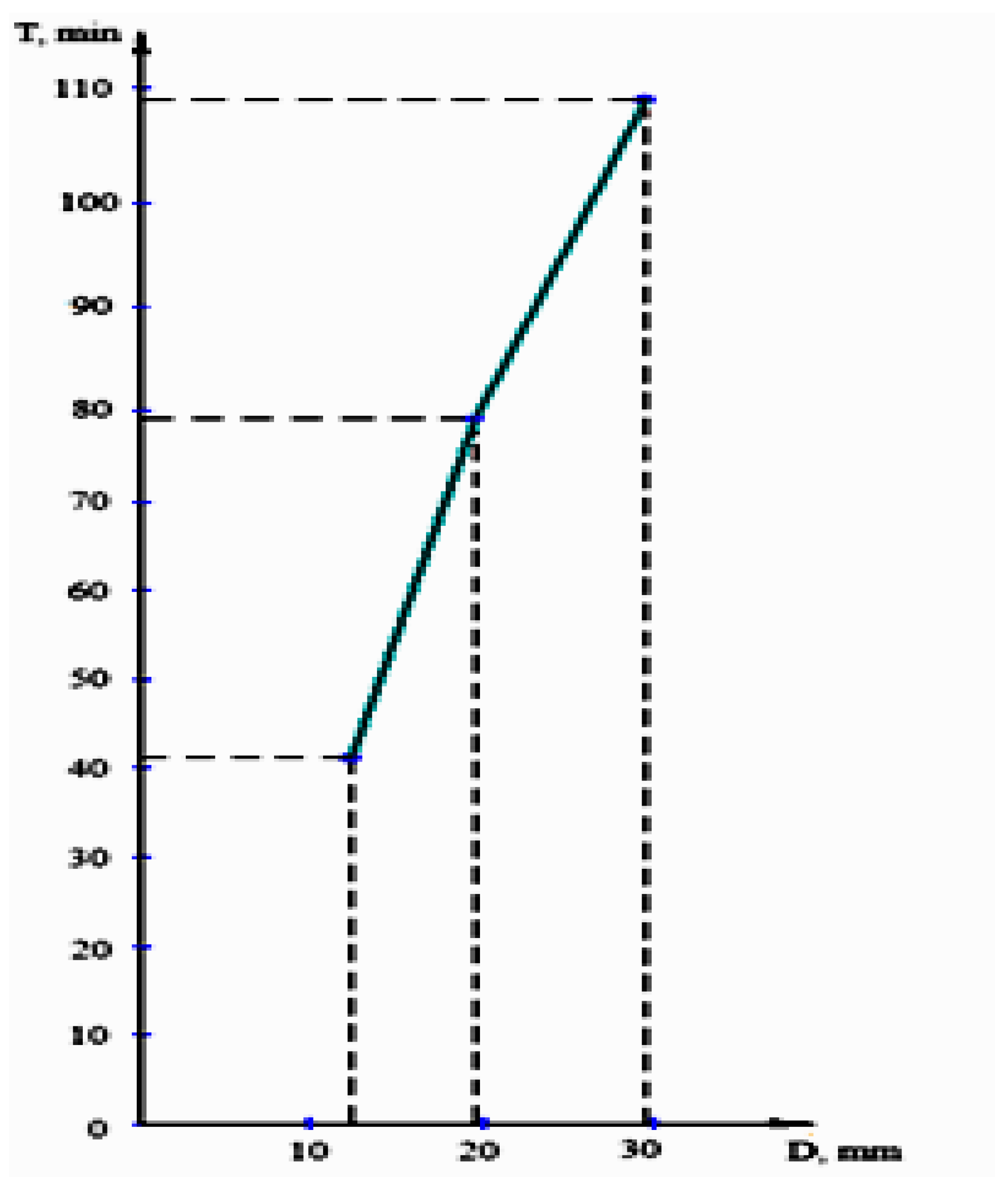
When processing holes with a double-edge spiral drill without a transverse edge with a diameter of 13,5 mm, the time to regrind was 42 minutes, for a standard drill – 20 minutes, which is 2,2 times higher (
Figure 15).
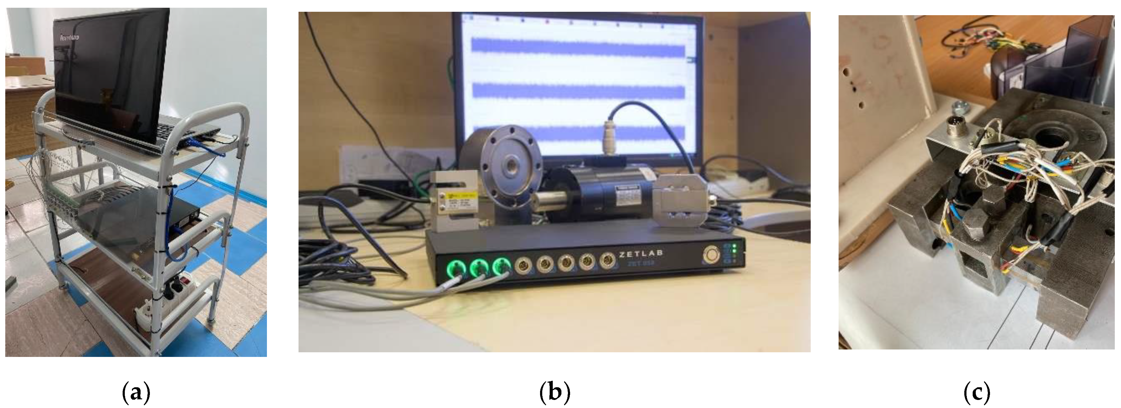
An experimental setup was used to determine the cutting forces acting on the drill (
Figure 16, a). It consists of a ZET 058 strain gauge measuring system (
Figure 16, b), Kistler force sensors (Multi-component dynamometers 9272, Dynoware 2825A software), a tool holder (
Figure 16, c), connecting cables and strain gauges.
Kistler force sensors are devices created using the piezoelectric effect of quartz. Such sensors are excellent for measuring cutting force in metal processing and other dynamic measurements in any given direction, regardless of the point at which the load is applied.
After machining the holes with twist and double-point twist drills, the accuracy of the diametrical size of the hole and the roughness were examined. To measure the accuracy of hole processing, an instrumental horizontal microscope IKG 3 and indicator bore gauges with inserts were used. To measure the surface roughness of the hole, a model 259 profilometer (produced by ZETLAB) was used.
Results of production tests of samples processed with metal-cutting tools:
- (1)
-
twist drills:
- -
the accuracy of the diametrical dimensions of the holes is 0,21-0,33mm (12-13 accuracy grade, according to GOST 25346-2016);
- -
The surface roughness of the holes is in the range Rz=20...80 micrometers, which corresponds to roughness classes 3 and 5, according to GOST 25346-2016.
- (2)
-
double-edge twist drills:
- -
the accuracy of the diametrical dimensions of the holes is 0,11-0,13 mm (11th grade of accuracy, according to GOST 25346-2016);
- -
The surface roughness of the holes is within the range of Ra=2,5...10 micrometers, which corresponds to roughness classes 4 and 6 according to GOST 2789-73.
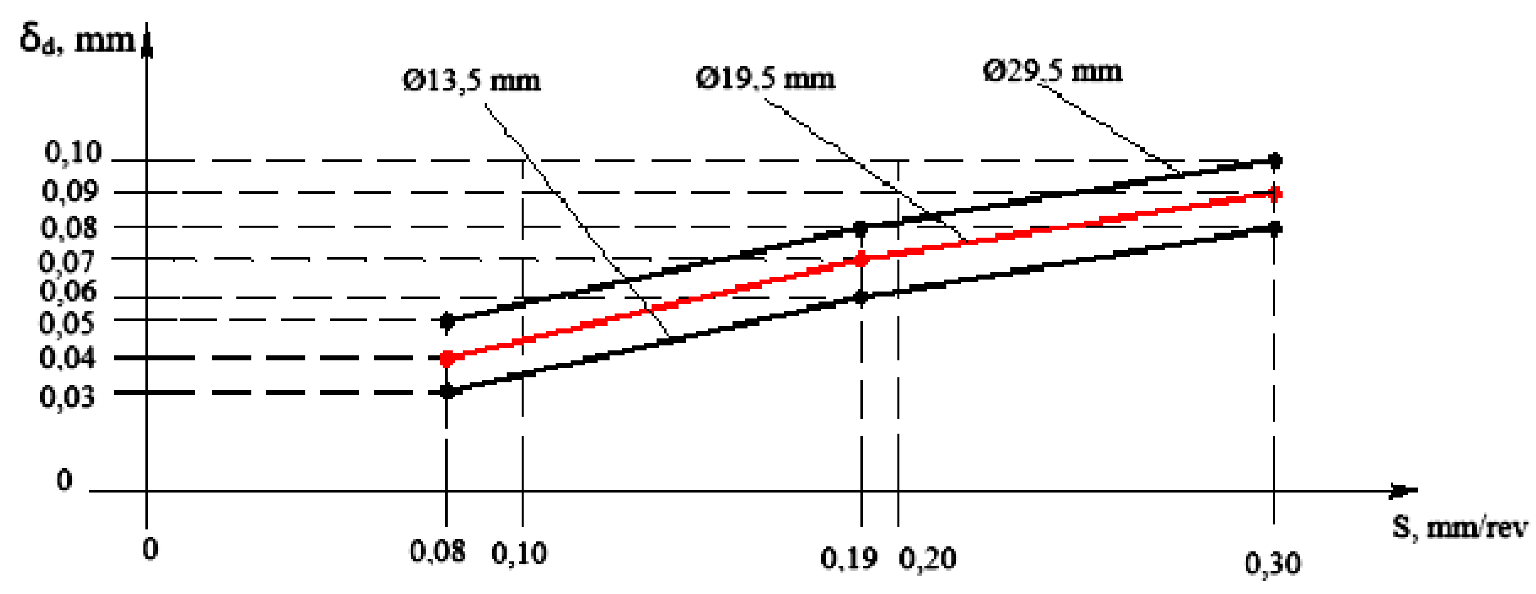
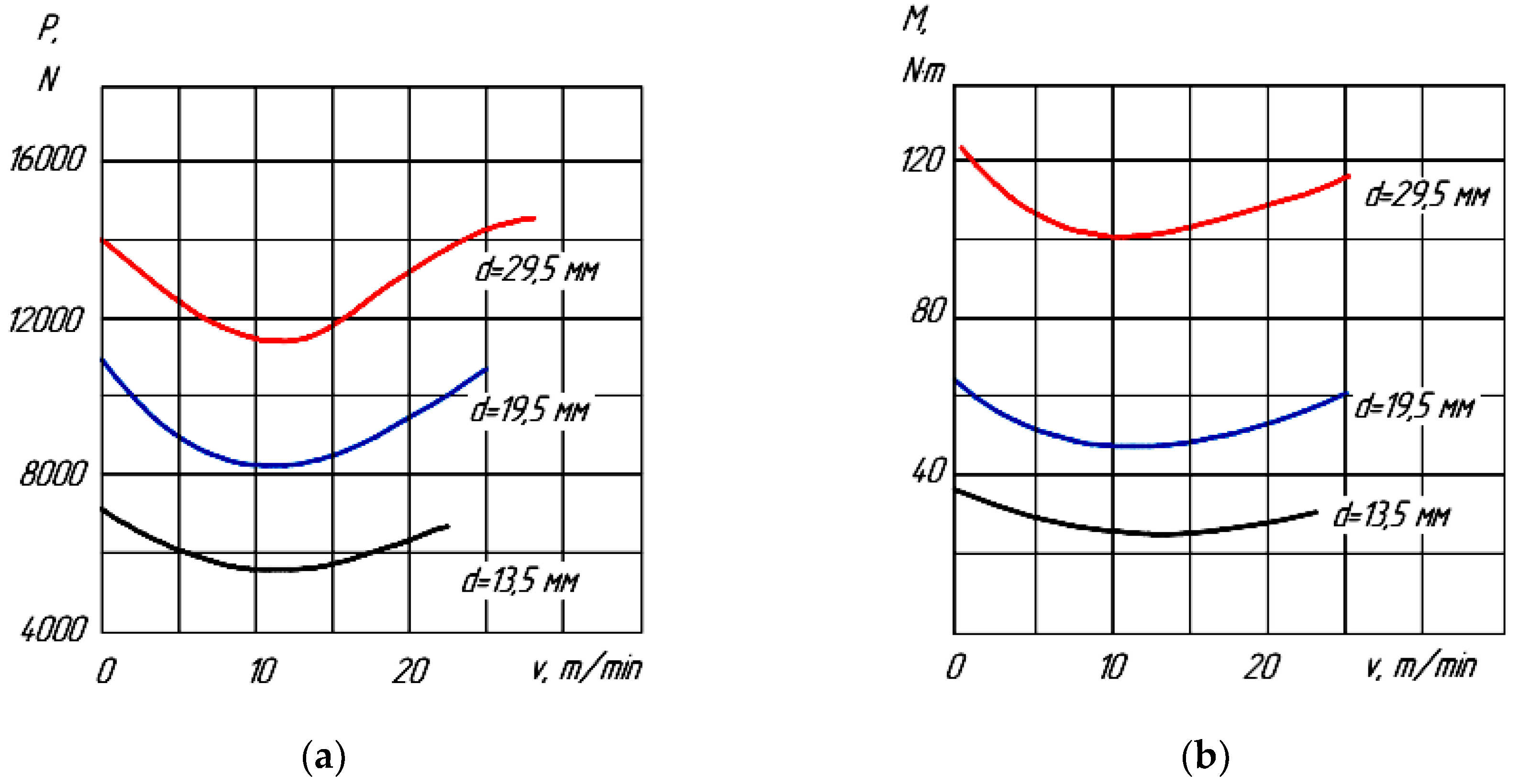
Based on the data obtained, deviations of diametrical dimensions, graphs were constructed depending on the accuracy of the diametrical dimensions of the machined holes on the spindle rotation speed and cutting feed (
Figure 17 and
Figure 18 ).
As can be seen from the graphs, deviations of diametrical dimensions decrease with increasing spindle speed and increase with increasing cutting feed. Deviations in the shape of the holes in the cross section were determined using a bore gauge, and the results were drawn up in the form of pie charts. The roughness of the surface of the holes was measured by the contact method using a profilometer.
The accuracy of the measurements of the processed samples is confirmed by certificates issued by the testing laboratory of the Technical Control Department of Pavlodar Machine-Building Plant JSC, as well as by the accredited testing laboratory of the Pavlodar branch of the National Center for Expertise and Certification JSC.
Experimental studies show that when using a two-blade spiral drill without a transverse edge, the surface quality of the holes is significantly improved: the roughness, the depth of the defective layer and the breakdown of the holes are reduced. This is due to the easier cutting conditions compared to conventional spiral drills with a cruciform edge, since the elimination of the cruciform edge reduces the loads on the tool and, as a result, increases its service life.
When conducting experimental studies, methods of experimental planning, mathematical statistics and parameter optimization theory were used. Processing of the experimental results and the necessary calculations were carried out using computer programs for plotting graphs of mathematical dependencies and approximating experimental data.
A technological route for sharpening a double-edge spiral drill without a transverse edge has been developed and optimal geometric parameters for sharpening a double-edge spiral drill without a transverse edge have been proposed, which will help increase the durability of the drill and the processing accuracy.
