1. Introduction
Piezoelectric ceramics are commonly tailored to suit various application scenarios, resulting in a classification into soft and hard piezoelectric ceramics based on specific parameter values. Soft piezoelectric ceramics are characterized by elevated piezoelectric constants (e.g., d33), high electromechanical coupling coefficients (e.g., kp), and notable dielectric loss (tanδ), alongside a reduced coercive field (Ec) and mechanical quality factor (Qm). These properties make them particularly suitable for applications such as ultrasonic atomization, remote sensing, and medical diagnostics. Conversely, hard piezoelectric ceramics are defined by their high mechanical quality factor (Qm) and low dielectric loss (tanδ), rendering them ideal for applications that demand high power output and efficient energy conversion. In high-power ultrasonic systems—such as those used in cutting, cleaning, and welding—hard piezoelectric ceramics play a critical role in ensuring system efficiency and stability. Their capabilities are especially vital in industrial and medical sectors where significant energy output is essential.
The hardening effect of PZT is typically achieved through acceptor doping, involving the substitution of Pb
2+ with Na
+ or Ti
4+ with Fe
3+ or Ni
2+. Currently, three mechanisms are proposed to elucidate the hardening effect of PZT [
1], as illustrated in
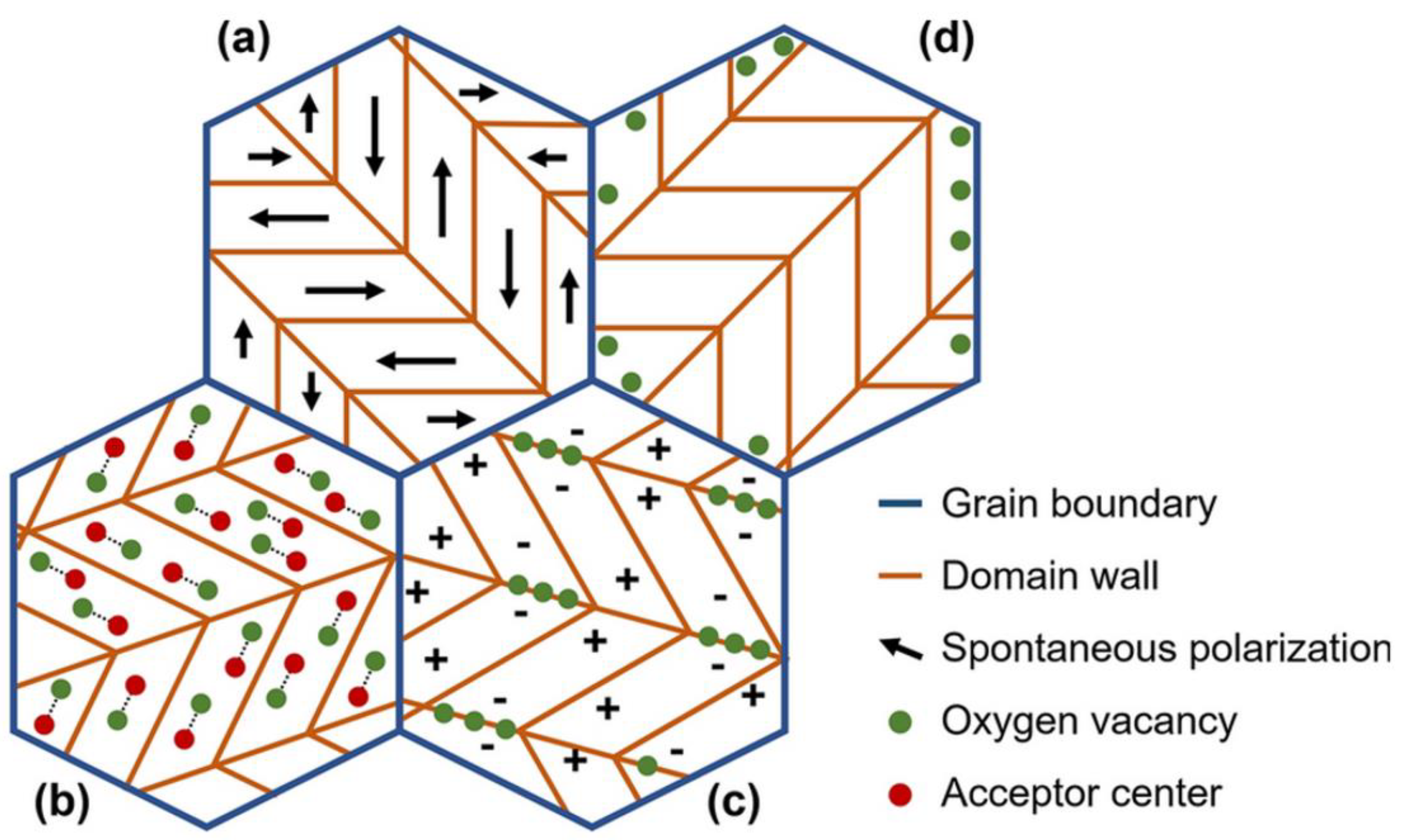
Figure 1: the bulk effect, domain-wall effect, and surface effect. In the bulk effect, positively charged oxygen vacancies are generated in acceptor-doped PZT to compensate for the negatively charged acceptor centers, resulting in the formation of "defect associations." These associations restrict domain wall movement and stabilize the domain structure, as shown in
Figure 1(b). The domain-wall effect, on the other hand, describes the migration of defects, such as oxygen vacancies, to the domain walls over time, thereby creating pinning centers that impede domain wall movement, as depicted in
Figure 1(c). The surface effect involves the diffusion of charged carriers towards the boundaries of the microstructure to counteract depolarization fields, which generates clamping forces that further limit domain wall movement, as illustrated in
Figure 1(d). Each of these mechanisms possesses unique applications, and determining their relative effectiveness remains challenging. Despite the established nature of PZT, its hardening mechanisms are not yet fully understood. The subsequent sections will address the control of hardening effect through doping in KNN.
Similar to PZT, the hardening effect of KNN predominantly depends on acceptor doping, with dopants including Cu
2+ and its compounds, such as CuO, K
4CuNb
8O
23 (KCN), and K
5.4Cu
1.3Ta
10O
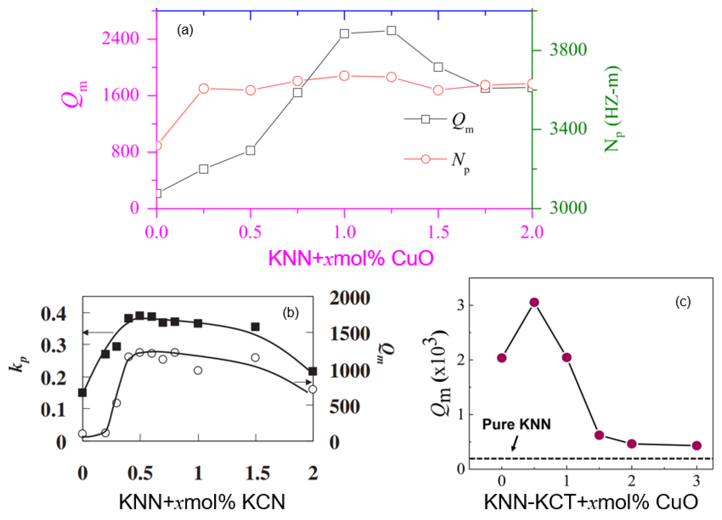
29 (KCT). The variations in the mechanical quality factor (
Qm) of doped KNN are illustrated in
Figure 2, with a summary of the data presented in
Table 1. The hardening mechanisms of KNN are largely analogous to those of PZT, primarily encompassing the bulk effect and domain-wall effect; however, they do not fully account for all experimental observations, necessitating further investigation [
1]. As shown in
Table 1, the
Qm of hardened KNN doped with CuO or KCT+CuO reaches 2500 and 3000, respectively, surpassing that of hard PZT, which is 2000. Nonetheless, the
d33 value of hardened KNN remains below 100, significantly lower than the 265 of hard PZT, which constrains its industrial applicability. Therefore, it is imperative to design KNN-based piezoelectric ceramics with improved overall performance. To this end, researchers have proposed ceramic composite systems to facilitate hardening effect control.
The BNT-BT-ZnO composite material was developed to tackle the issue of thermal depolarization in the BNT-BT system. A study by Zhang in 2015 demonstrated that ZnO effectively delays the depolarization temperature, whereas ZrO
2 does not exhibit a similar effect, underscoring the distinctive properties of ZnO [
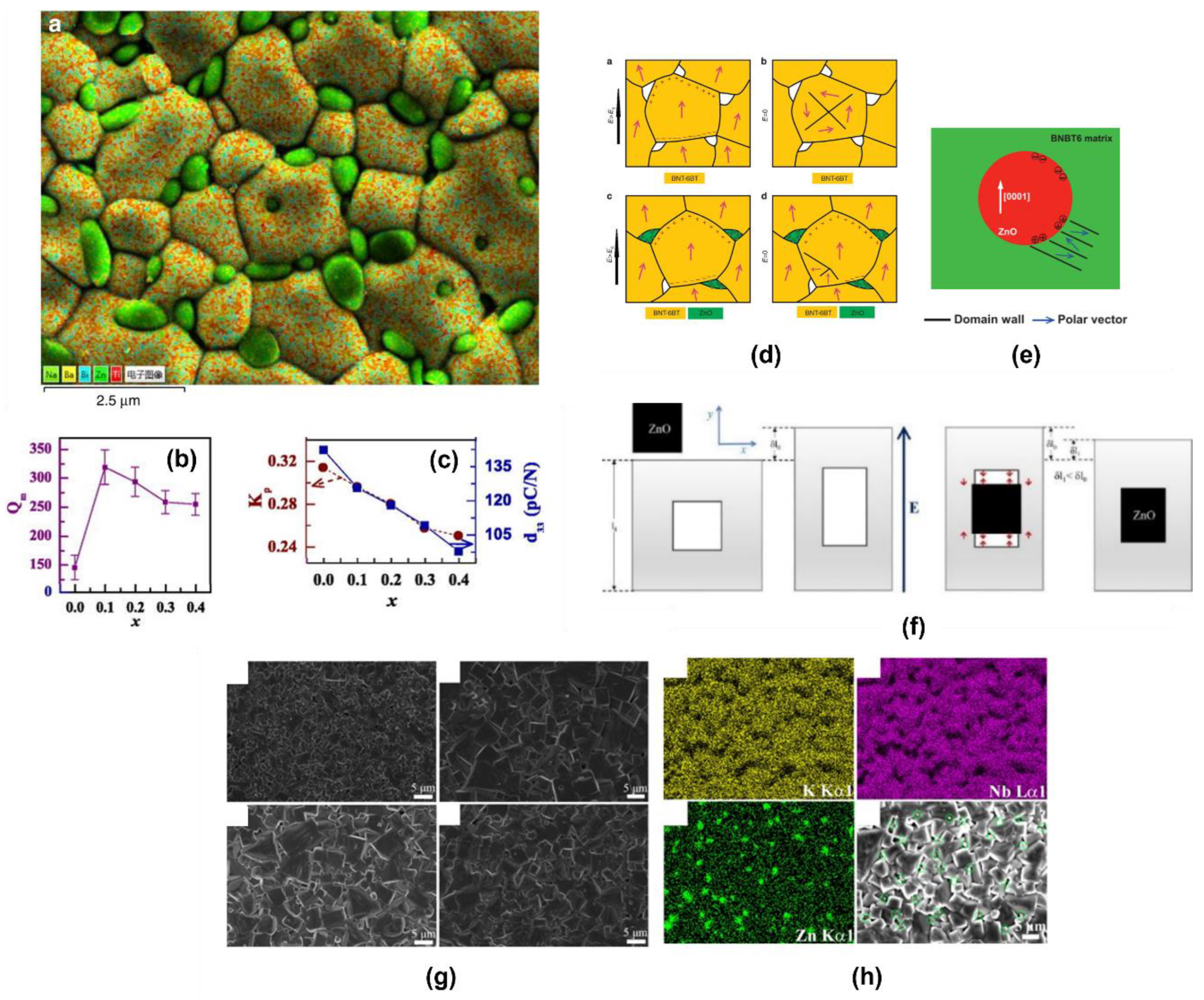
9]. In this composite, ZnO particles are situated at the grain boundaries of BNT-BT, forming a 0-3 type composite material, as illustrated in
Figure 3. Several models have been proposed to elucidate the mechanism behind depolarization suppression in BNT-BT-ZnO composites, including the "charge compensation model," the "pinning effect of ZnO on nanoscale ferroelectric domains" [
10], the "thermal stress-induced ferroelectric phase stability" model [
11], and the model concerning Zn incorporation into the lattice [
12]. All these models relate to the enhanced stability of ferroelectric domains and phases, which contribute to an increase in the mechanical quality factor (
Qm). Thus, linking the suppression of thermal depolarization to the enhanccement of
Qm represents an innovative approach.
In 2017, it was observed that the hardening effect of the BNT-BT-ZnO composite system was significantly enhanced, with
Qm increasing in proportion to the ZnO content, as depicted in
Figure 3 [
13]. While the aforementioned models can account for the increase in
Qm with higher ZnO content, they fail to explain the subsequent decrease in
Qm when ZnO content is further increased. Consequently, a clamping effect due to strain incompatibility caused by ZnO was proposed, as shown in
Figure 3 [
13]. Given the inferior piezoelectric response of ZnO compared to the BNT-BT matrix, the strain in the two phases becomes inconsistent, necessitating that the matrix accommodate the strain of ZnO. This accommodation leads to restricted matrix strain, reduced domain switching losses, and an increase in
Qm. However, excessive clamping can elevate domain wall density, resulting in higher energy loss and a decrease in
Qm. This model thus presents a competitive mechanism whereby ZnO limits the matrix strain without excessive clamping, thereby preventing undue stress and a high domain wall density in the matrix. Ultimately, an optimal
Qm can be attained by identifying the best compositional balance.
Previous research has introduced BNT-BT-ZnO composites and their hardening performance regulation, with analogous studies being applied to the KNN system. Some researchers have attempted to develop KNN-ZnO composites [
14], as shown in
Figure 3, which includes SEM images and elemental distribution. The density of ZnO is reported as 5.60 g/cm³, while the theoretical density of pure KNN is 4.51 g/cm³. In this study, the density of pure KNN was relatively low, measured at only 4.00 g/cm³, indicating a densification of less than 90%. Although the density of KNN-ZnO increased with higher ZnO content, the overall density level remained suboptimal [
14]. This study primarily explored the properties of KNN-ZnO composites, such as the temperature stability of
d33, while the investigation of hardening performance has yet to be addressed. The present work aims to fill this gap.
2. Results and Discussion
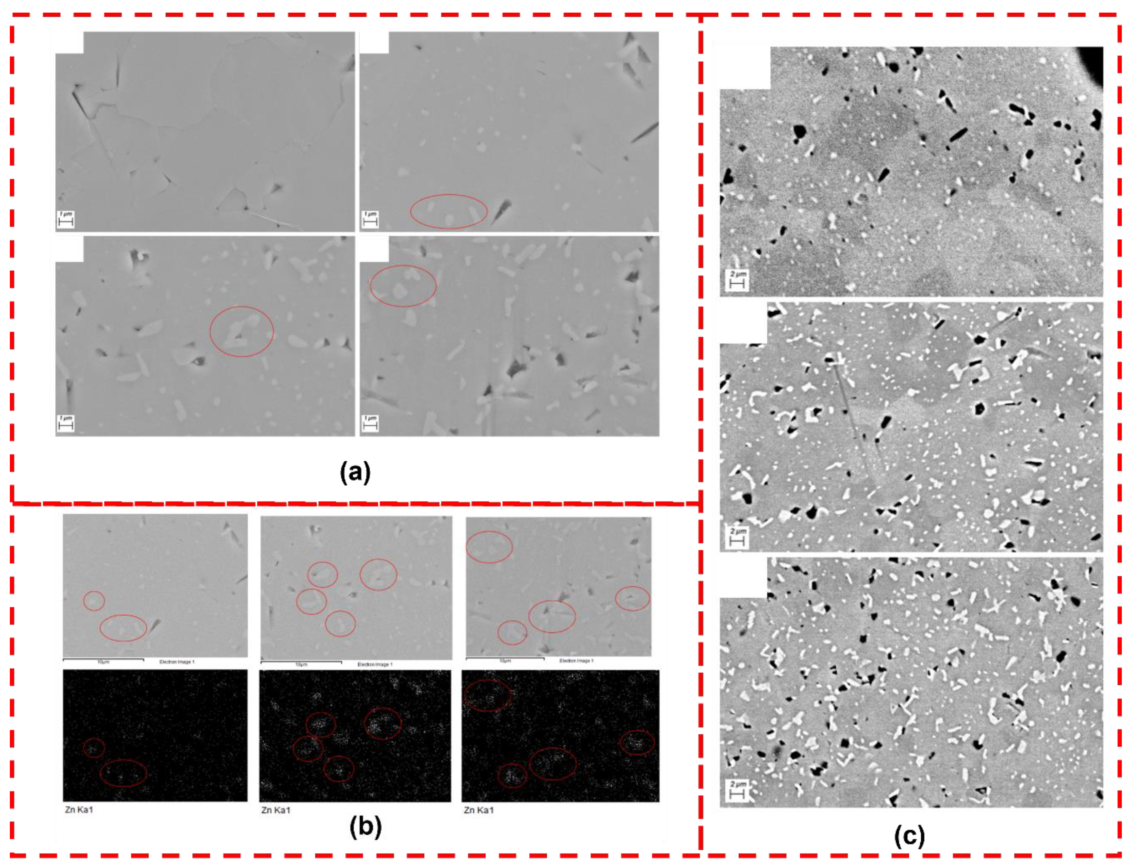
The SEM pictures of KNN-ZnO composites prepared by hot pressing under an inert atmosphere are presented in
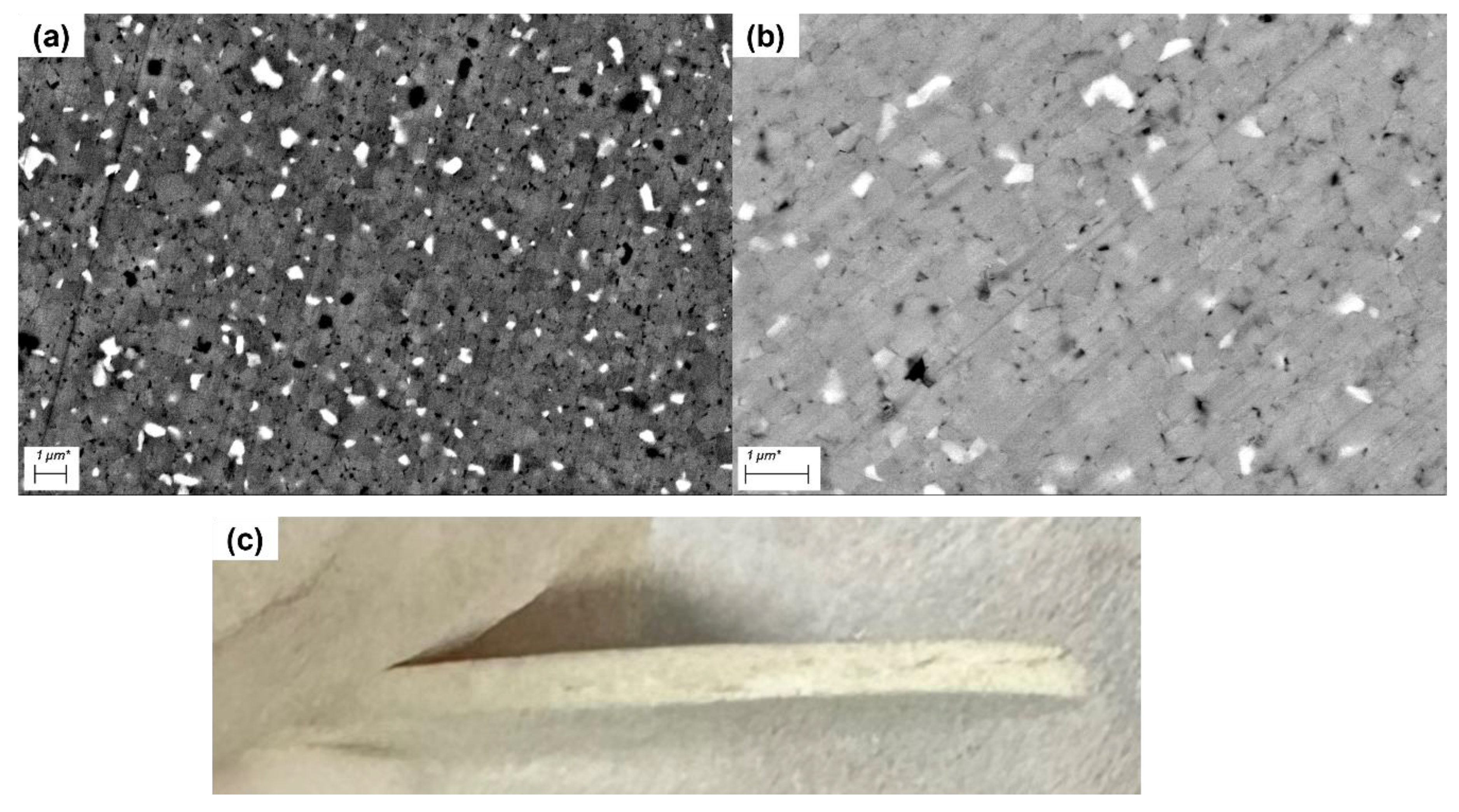
Figure 4. In these images, ZnO particles appear as white spots, uniformly distributed within the KNN matrix. Each sub-figure highlights the ZnO particles with red circles for clarity. It is evident that, with increasing ZnO content, both the number and distribution density of the white particles (ZnO) increase correspondingly, aligning with theoretical expectations. Additionally, the higher ZnO content is associated with an increased pore density, which may be attributed to the mismatch in thermal expansion coefficients between ZnO and KNN during the annealing process, resulting in crack formation at the interface.
To confirm that the white spots observed in
Figure 4 are indeed ZnO particles, energy dispersive X-ray spectroscopy (EDS) was conducted on the same region, specifically analyzing the Zn element, as shown in
Figure 4. The upper images in
Figure 4 correspond to the images below. Initially, a secondary electron image was obtained, followed by EDS scanning of the same area, resulting in a continuous dataset of secondary electron and EDS images. The red circles in
Figure 4 indicate the corresponding locations in both the secondary electron and EDS images, confirming that the white spots are regions enriched in Zn content, thereby validating their identification as ZnO particles.
To distinctly differentiate between ZnO and KNN in the material, backscattered electron (BSD) images were acquired, as shown in
Figure 4. According to the literature [
15], the backscattering coefficients of the different phases were calculated, with higher backscattering coefficients producing brighter areas in the BSD images. The backscattering coefficient of ZnO is slightly higher than that of KNN, resulting in bright white regions in
Figure 4 corresponding to the ZnO phase, gray regions representing the KNN matrix, and black regions indicating pores. Compared to the secondary electron images, BSD images demonstrate superior contrast, facilitating a clearer distinction between the ZnO and KNN phases.
From the images, it is apparent that as the ZnO content increases, the total area of the white regions (ZnO phase) also increases in accordance with expectations. Furthermore, the density of the black regions (pores) significantly rises with increased ZnO content. This phenomenon may arise from the thermal expansion mismatch between ZnO and KNN during annealing, or it may be attributed to the enhanced sintering aid effect of ZnO, which, at higher contents, results in an excessive liquid phase formation during hot pressing, ultimately leading to pore formation.
Based on the SEM images, the microstructure of the KNN-ZnO composite prepared in this study markedly differs from that of the BNT-BT-ZnO composite reported in the literature. In this work, KNN grains exhibited rapid growth, resulting in larger grain sizes that partially engulf small ZnO particles, leading to a microstructure in which KNN grains encapsulate ZnO particles. Conversely, the literature describes the BNT-BT-ZnO composite with ZnO particles uniformly distributed along the grain boundaries. These distinct microstructures contribute to differences in the internal stress distribution within the material.
The encapsulation of ZnO particles by KNN grains may lead to a more complex stress distribution during the sintering process, whereas the literature-reported structure, with ZnO uniformly distributed at the grain boundaries, facilitates a more homogeneous stress distribution. Consequently, to achieve a structure where ZnO is uniformly distributed at the grain boundaries, as noted in the literature, it is essential to adjust the sintering conditions to inhibit excessive KNN grain growth, promoting a more uniform distribution of ZnO.
To achieve this objective, the study made specific adjustments to the sintering conditions, including optimizing the sintering temperature and time to suppress KNN grain growth, thereby obtaining a microstructure more aligned with that reported in the literature. Following these optimizations, SEM images were captured, as shown in
Figure 5, demonstrating that the distribution of ZnO particles in the optimized material is more uniform, and the size of KNN grains has decreased, aligning more closely with the literature description.
As illustrated in
Figure 5, although the optimized sintering conditions successfully produced a composite structure with ZnO particles uniformly distributed among KNN grains, several significant issues arose post-annealing. The disparity in thermal expansion coefficients between KNN and ZnO resulted in the formation of numerous microcracks within the material upon cooling to room temperature. Some cracks even manifested as visible fractures at the sample edges. This observation indicates that while hot pressing in an inert atmosphere effectively promotes the integration of ZnO and KNN, the thermal expansion mismatch during annealing induces considerable internal stress, ultimately resulting in microcrack and fracture formation.
These findings highlight the limitations of hot pressing under inert conditions for preparing composite materials, particularly those requiring subsequent annealing. While the annealing step aims to enhance the microstructure and reduce defects, the thermal expansion mismatch between KNN and ZnO phases renders annealing a critical factor that adversely impacts the structural integrity of the material, leading to reduced mechanical stability.
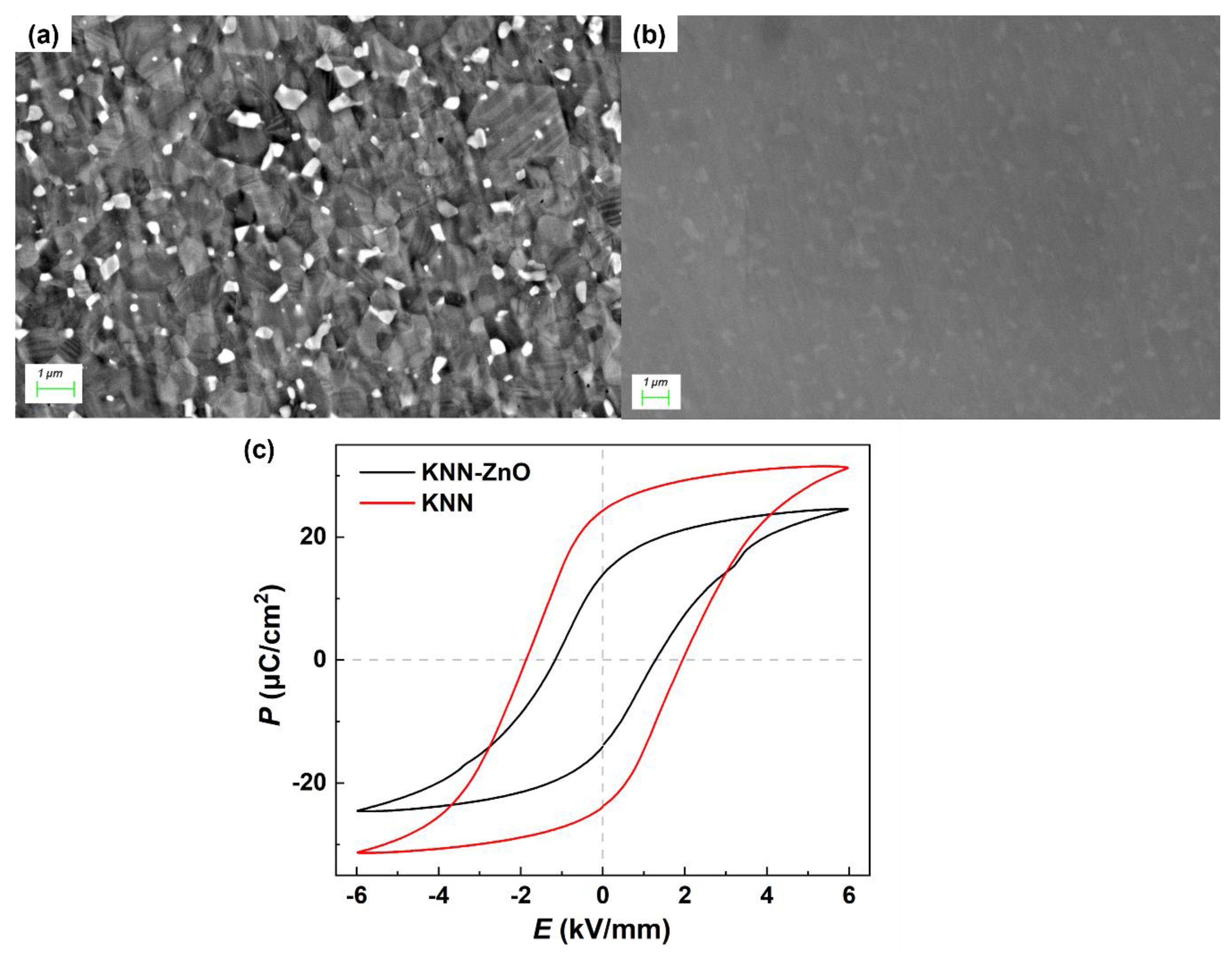
To mitigate the impact of the annealing step, this study further explored hot pressing in an oxygen atmosphere while strictly controlling sintering conditions to inhibit KNN grain growth, aiming to fabricate KNN-ZnO composites with improved structure and density. The SEM images of the sintered samples are presented in
Figure 6, with
Figure 6(a) displaying the secondary electron image and
Figure 6(b) showing the backscattered electron image.
As depicted in
Figure 6, hot pressing in an oxygen atmosphere, combined with optimized sintering parameters, successfully yielded a KNN-ZnO composite with a structure analogous to that described in the literature. ZnO particles were uniformly distributed among KNN grains, and KNN grain growth was effectively suppressed, resulting in significantly smaller grain sizes and a uniform overall structure. Additionally, the backscattered electron image reveals a very high density with almost no pores, indicating a substantial improvement in material densification through the hot pressing process in an oxygen atmosphere.
These results suggest that employing hot pressing in an oxygen atmosphere not only effectively circumvents the issues associated with the annealing step but also markedly enhances the quality of the composite's microstructure, yielding a more uniform distribution of KNN grains and ZnO particles, further increasing the density and structural integrity of the composite material.
Subsequent electrical performance testing was conducted on the prepared KNN-ZnO composite, including assessments of ferroelectric hysteresis loops, piezoelectric constant (
d33), and impedance spectroscopy. The results, presented in
Figure 6, indicate that the ferroelectric hysteresis loops of the composite material exhibited a decrease in maximum polarization, remnant polarization, and coercive field compared to pure KNN. This reduction can be attributed to the incorporation of ZnO, a non-ferroelectric heterogeneous phase, into the KNN matrix, which diminishes the overall ferroelectric properties and weakens polarization characteristics.
Furthermore, the testing results for
d33, electromechanical quality factor (
Qm), and maximum phase angle are summarized in
Table 2. Compared to pure KNN, the
d33 and maximum phase angle of the ZnO-composited samples decreased to varying extents, while the
Qm value increased by 40%. Despite this enhancement, the overall
Qm remains relatively low, suggesting that while the introduction of ZnO has improved the electromechanical quality factor to some degree, the extent of enhancement is still less significant than that observed in the BNT-BT system reported in the literature. This may be linked to the properties of the matrix material; the BNT matrix, as noted in the literature, possesses a higher Young's modulus than KNN, potentially resulting in more pronounced modification effects when combined with ZnO, thereby exhibiting greater improvements in electrical performance.
4. Experimental
The preparation of KNN powder commenced with batching a total powder weight of 60 grams per ball mill jar, with four jars prepared in total. The raw powders were mixed and placed into the ball mill jars, followed by the addition of ethanol. The mixture underwent an initial ball milling process for 24 hours. After milling, the slurry was dried and subjected to preliminary calcination to obtain the perovskite phase of KNN. The calcined powder was then milled for an additional 24 hours, dried, and sieved through a 60-mesh sieve to yield the KNN powder.
Subsequently, KNN+xZnO powder was prepared using ZnO with a purity of 99%, purchased from Xianfeng Nano. The KNN powder was mixed with varying masses of ZnO. This mixed powder underwent a third round of ball milling for 24 hours, followed by drying and sieving through a 60-mesh sieve to produce the KNN+xZnO powder.
The KNN+xZnO powder was loaded into a hot-pressing mold and sintered under an inert atmosphere of argon. The resulting hot-pressed samples were cylindrical, with a diameter of approximately 24.5 mm and a thickness of about 4.3 mm, exhibiting a uniform black color attributed to carbonization from the graphite mold and oxygen deficiency during the sintering process. The formation of numerous oxygen vacancies contributed to the development of defect energy levels within the bandgap, enhancing light absorption and resulting in the black appearance of the samples.
The hot-pressed cylindrical samples were then cut into rectangular specimens measuring 6.5 × 6.5 × 1.5 mm, which also displayed a black color. These rectangular specimens underwent annealing in an air atmosphere to ensure adequate compensation of oxygen vacancies. To minimize the volatilization of alkali metal elements during annealing, the samples were embedded in corresponding powders.
Following annealing, the rectangular specimens were polished to a standard size of 6 × 6 × 1 mm. The annealed samples initially appeared white, with the color gradually darkening to yellow as the ZnO content increased. Silver electrodes were then applied to the surfaces of the specimens, and any residual silver on the edges was removed. The prepared samples were subsequently subjected to X-ray diffraction (XRD), scanning electron microscopy (SEM), and relevant electrical performance testing.
XRD analysis was conducted using a Rigaku model X-ray diffractometer. SEM characterization was performed with a ZEISS Merlin scanning electron microscope to observe the surface morphology and elemental distribution of the samples. Dielectric spectroscopy was tested using a TZDM model RT-800 and a Tonghui TH2827C Precision LCR Meter. Poling treatment was carried out with an ET2673D-4 piezoelectric ceramic high-voltage poling apparatus (Nanjing En Tai Electronic Instrument Co., Ltd.), applying a poling field of 3 kV/mm at 120 °C. The d33 values were measured using a ZJ-3A quasi-static d33 meter from the Chinese Academy of Sciences Institute of Acoustics. Ferroelectric hysteresis loops were recorded using a TF ANALYZER 1000 (aixACCT), and impedance analysis was conducted with a Tonghui TH2839 Impedance Analyzer.
