1. Introduction
Manipulation tasks often require the manual definition of grasping poses. This process is very time-costly, as all the poses must be validated with the real robot. Hence, current lines of research on this matter are focusing on automatising the grasping pose estimation. The correct recognition of these points is essential in any manipulation task, specially in industrial scenarios, where efficiency and grasp quality take an essential role, thus making the grasping point identification a key area of research within the robotics community.
The current research tendencies follow two main approaches [
1,
2], depending on whether the morphology of the piece is available beforehand (model-based approaches) or not (model-free approaches). Each approach has its lights and shadows; on the one hand, model-free approaches are attractive as they try to calculate grasping points regardless of the piece, sacrificing overall accuracy and gaining flexibility. On the other hand, model-based approaches can give grasping points specially tailored for each piece, gaining precision but sacrificing scalability and generalisation and, of course, requiring the model of the object. As it can be seen, the two approaches portray the dichotomy between accuracy and scalability.
Moreover, due to the emergence of deep neural models and artificial intelligence (AI) techniques, researchers of the field of robotics are using those learning based approaches in the context of grasping point detection. However, this comes with inherent drawbacks, being the most important the amount of data needed to train grasping point identification models. Generating data in real systems is costly both in terms of time and economy. Thus, a popular go-to approach is to get the data from simulation. This can be corroborated with the raise in popularity of simulators such as Google DeepMind’s MuJoCo [
3], NVidia’s Isaac Sim and Isaac Lab [
4], Unity, with tools such as Unity Robotics Hub [
5], PyBullet [
6] and so on. For instance,
Zhang et. al. [
7] developed a convolutional neural network (CNN) specially tailored to ease the process of grasping cables in cluttered environment, called CG-CNN (Cable Grasping Convolutional Neural Network). In this case, they use the PyBullet simulator to generate numerous scenes, applying domain randomisation, and thus collect a diverse dataset. Then, their GC-CNN is trained with the synthetic dataset, thus obtaining a model that can predict the grasp qualities. Then, in the article they explore two different grasping order strategies: random policy and estimated quality based policy, where they report that the grasping quality approach outperforms the random grasping order policy. In [
8] they propose an end-to-end system that predicts the poses, categories and scores directly, taking the pointcloud as input and without the need of sampling, as they deem the sampling process to be time costly. Adding to that, to generate the training data of cluttered scenes, they propose an approach based on Ferrari-Canny metric, as well as the use PyBullet to create the train data for multi-object grasp planning. They report better result in clutter removal experiments than contemporary studies
Further studying the model-free approaches, literature shows that the traditional strategy is to use visual information given by cameras [
9]. These approaches are appealing due to the fact that the system is focused onto generalising to never seen before objects or variable environment conditions. Nonetheless, the cost of lacking prior model knowledge is that the system is limited to the information seen by the sensors on the moment of picking, which are susceptible to noise, thus sacrificing overall accuracy. In [
10] the researchers develop a grasp detection module based on keypoints that achieves real-time estimation in both CPU and GPU, and report a grasping success of 96% with a real robot. To train and validate their system, they use the Cornell [
11] and Jacquard [
12] grasp datasets, both formed by grasps annotated using simulation. The work in [
13] showcases the development of a Grasp Pose Domain Adaptation Network with the main task of detecting possible 6 degrees of freedom (DoF) grasping poses in cluttered workspaces. They carry out experiments using the publicly available GraspNet-1 Billion [
14] and Acronym [
15] grasping pose datasets. Adding to that, Acronym is based on simulation, and offers the option of generating cluttered scenes.
With respect to the model-based approaches, [
16] propose a self-supervised robot system for 6D object pose estimation. Regarding the grasping poses themselves, the authors take 100 samples from the grasps calculated in [
17], and choose the grasps that are kinematically valid. In [
18], a learning-based approach for rigid objects in cluttered scenarios is presented. The grasp and placement trials are carried out in a simulated environment, using V-Rep [
19], transferring them to the real world. In their approach, points are sampled from the surface of the object and then, using the unsupervised learning partitioning around medoids (PAM) technique they reduce the number of points. Researchers in [
20], use the Computer Aided Design (CAD) of the object as an input of their system in order to sample a set of accessible grasps e.g. grasps that do not collide with the environment, and to attach to each grasp a set of simulated visuotactile images, to form a grasp database. When the object is seen, the system samples grasping pose candidates and tries to match the candidates with the ones in the database, thus obtaining the fittest grasping pose. They measure the fitness of a grasp based on the simulated contact images, the probability of a grasp giving good visuotactile information and the length of the motion needed to grasp the object, as well as the number of regrasps needed.
The deep analysis of the state of the art allows us to argue that the tendencies are inclining towards model-free on-line grasping point calculation, as they flexible alternatives that allow the system to adapt to never seen pieces without the need of re-adjusting the system. A good amount of these works propose using learning-based techniques to solve this challenge, while not focusing in detail about the grasp pose estimation of their approaches of their work, as stated in [
17]. As previously mentioned, learning-based approaches need a large amount of data. Our work proposes a self-supervised grasp pose estimation system that uses the MuJoCo simulator to generate grasping poses for a given CAD in Wavefront Obj format. This generated points can either be used to pick the object using the obtained grasping poses directly or to train learning based approaches. There are some works that are similar to ours, in the sense that they also cover the automatic generation of grasping poses for a given set of objects using CADs as input, namely ACRONYM [
21], and MultiGripperGrasp [
22]. To generate their database, in Acronym they use the meshes available from ShapeNetSem [
23], sample grasping points using an antipodal sampling scheme and label them using the Nvidia FleX [
24] simulator. Their evaluation procedure consists on grasping the object in a gravity-less environment and then shaking it. Their dataset also enables the creation of cluttered scenes. MultiGripperGrasp also consists on a dataset containing labeled grasping poses with different grippers and objects as well as it let’s the user add new grippers and objects, assuming they are well modelled. The objects contained in their dataset consist on a set of 329 objects from the GoogleScannedObjects dataset [
25] and 16 objects from the YCB dataset [
26]. To estimate the grasps, they first use GraspIt [
27] to sample candidates from the object and then use Isaac Sim [
28] to evaluate each grasping candidate. This evaluation consists on monitoring the time of fall-off for each object, and assigning the time as a score. It is noteworthy mentioning that in both previous approaches, a standard value has been used for all the objects’ physical parameters. In Acronym the friction is set to 1.0 and density to 150 kg/m³, while in MultiGripperGrasp, the frictions, both static and dynamic are set to 0.5 and the density to 100 kg/m³.
This manuscript directly compares our system with MultiGripperGrasp. Furthermore, we achieve improvements in the following aspects:
Time per grasp. We use the full CPU in order to optimise the grasp generation process, making it around 18 times faster than their approach, without loosing grasp accuracy.
Similarity to manually defined grasp poses. The grasps estimated by our system are more similar to a manually defined ground truth.
System requirements. Our system runs on CPU and adapts to the amount of threads this CPU has. It does not need a dedicated RTX-Enabled GPU.
This document is organised as follows:
Section 2 describes the system architecture, emphasising in the communication between the different elements.
Section 3 presents the grasp validation pipeline, explaining all the steps of the logic of execution.
Section 4 presents the experimentation followed to validate and quantify the fitness of the system, while
Section 5 showcases the results obtained from said experimentation process. Finally,
Section 6 collects the conclusions and lessons learned from this work.
2. System Architecture
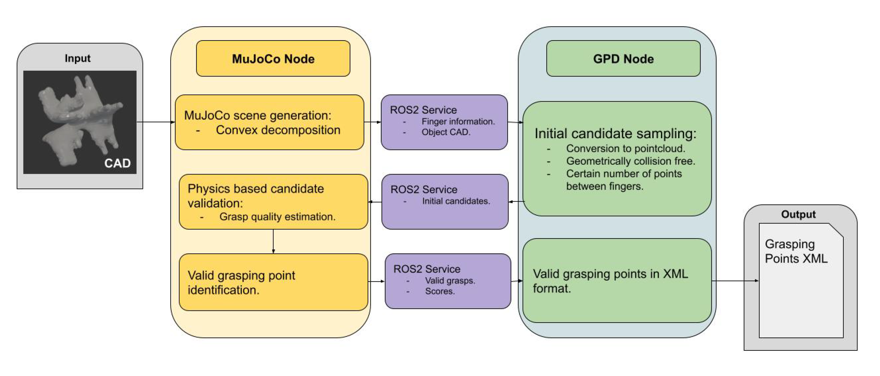
The work presented in this paper proposes a two stage system; an initial candidate sampler, using a modified version of GPD [
29], and the realistic simulation environment using MuJoCo, both integrated within the ROS2 ecosystem. This section digs deep both into the communication between the parts as well as the technical aspects of the implementation of each part, portrayed in
Figure 1.
2.1. GPD Integration
As stated before, GPD has been integrated into the architecture encapsulated as a ROS2 node, providing custom ROS2 services as the server, and has been dockerised. When the docker is started, it launches the node in charge of initiating the two main service servers:
Initial grasp sampler service: This service receives the object model (CAD), as well as the information about the gripper and the fingers, this is, the height, width and depth of the fingers, the distance between them and the grasp mode it allows, either inner grasps, outer grasps or both. With all this information, it produces the grasping point candidates, each including the 6D pose of the object with respect to the gripper. Originally, GPD returned the pose of the gripper in the object’s coordinate system, but we inverted the pose to obtain the pose of the object in gripper coordinates in order to ease the validation process in the simulation. Finally, more information about the initial candidate estimation is presented later in this very section.
File generation service: The service receives as input a list of 6D grasping poses after being validated in the simulator, as well as the list of poses "discovered" in the validation process and outputs a confirmation message, finally generating a XML file containing the validated grasps. The term of "discovered" grasping poses is further explored in
Section 3.
Moreover, the original GPD implementation has been enhanced to allow having CADs as input, to later convert them to pointcloud format, as no camera is involved in the self-supervised grasp pose estimation process. Adding to that, GPD has also been strengthened to allow the estimation of inner grasps.
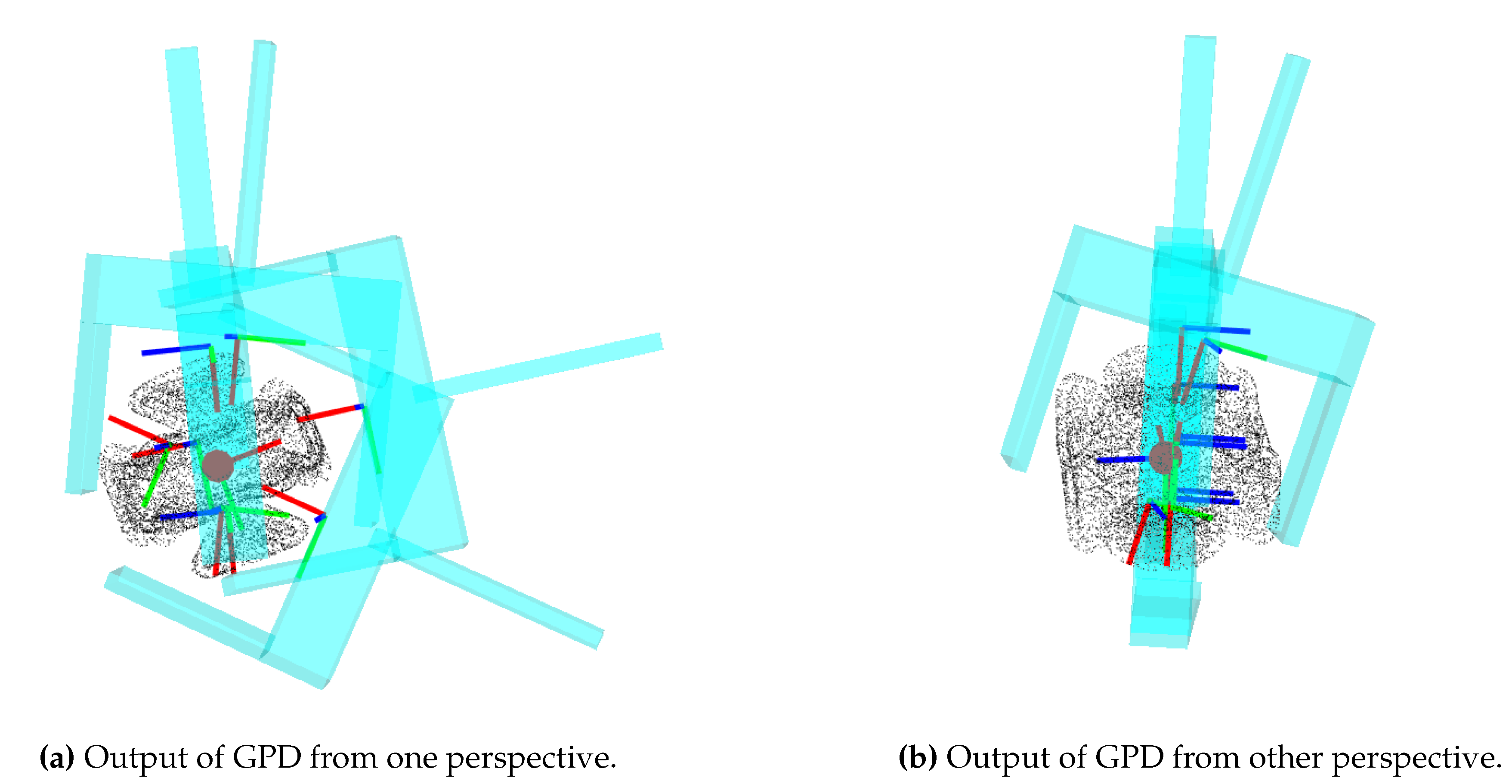
Regarding the initial candidate estimation, this enhanced GPD part iterates over an initially defined number of grasp candidates, also taking into account a defined number of orientations, and checks whether the grasp is geometrically viable, this is, if the gripper does not collide with the fingers, as well as the amount of points from the pointcloud that are between the grasps, since a threshold is defined to determine the minimum amount of points that have to exist between the fingers in order to be considered a good candidate.
Figure 2 shows an example of the initial candidate estimation and sampling using GPD.
2.2. Simulation Environment
As mentioned previously, the simulation environment is based on the popular MuJoCo
1 physics engine. Most precisely, it’s native Python bindings have been used. MuJoCo has been chosen as our go-to physics engine as it is open source, very regularly updated, with an active community, does not need a dedicated GPU nor a high-end machine to work and most importantly because it is focused on contact rich scenarios, which are the basis of robotic manipulation.
The simulation environment has been merged into the system architecture also as a ROS2 node, acting as the ROS2 service client to the aforementioned initial grasp sampler and file generation services.
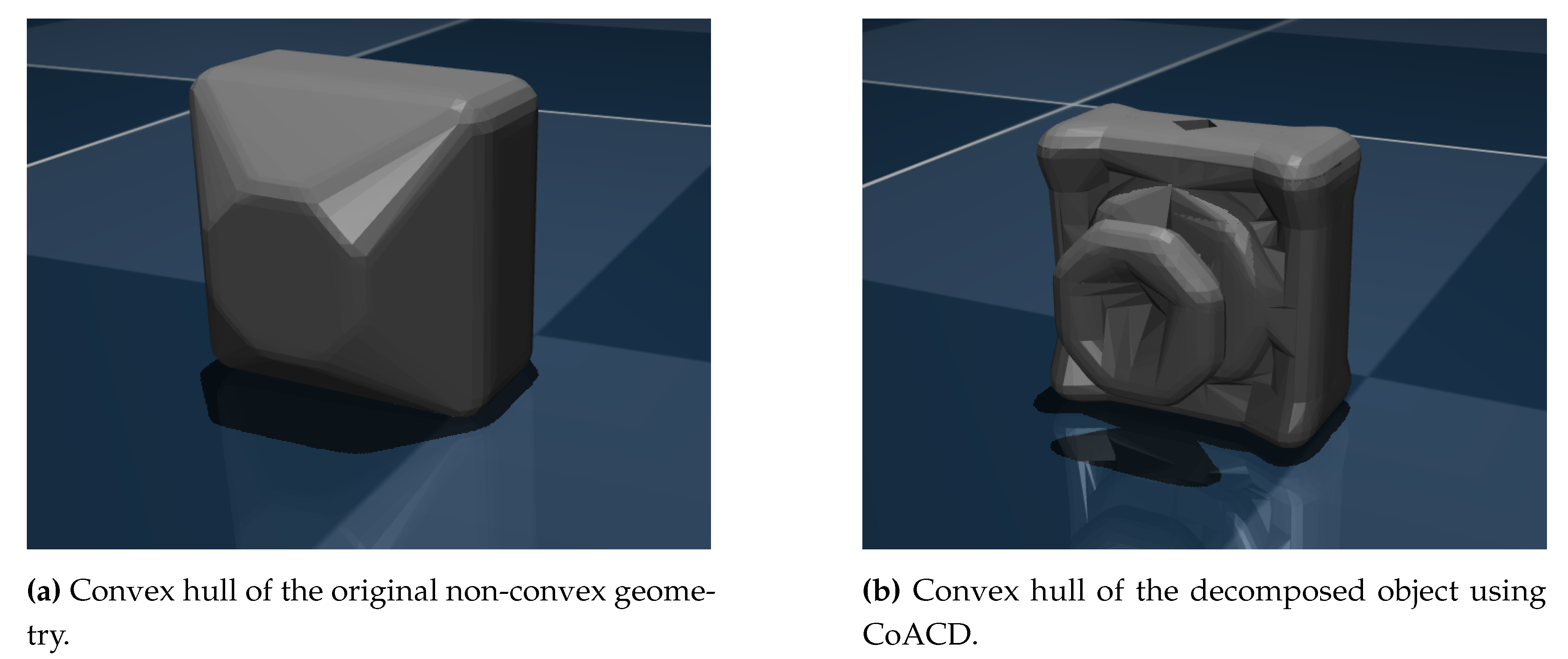
Digging deeper into the implementation, it must be noted that MuJoCo works with the convex hulls of the objects in order to calculate the collisions. This is also a popular approach on video game engines, due to computational reasons. Thus, as we seek the maximum amount of physical realism on contacts, which the convex hull does not provide, we have used convex decomposition software to subdivide the original geometry into smaller and convex ones (see
Figure 3). This vastly increases the realism on contacts by sacrificing computational power as, in essence, by subdividing the geometry into smaller ones we are creating more geometries which translates in practice to more contacts. This is why it is also vital to find an equilibrium between computational power and realism in contacts.
Initially we tested the objects using V-HACD
2, but the results where not what we where searching for, as V-HACD removed the concavities in the objects, loosing realism as consequence. Hence, we opted to use CoACD
3.
This software is tailored to preserve the concavities of the objects, and offers a good amount of parameters that enables us to fully customise the convex subdivision operative. It offers the ability to limit the amount of convex geometries created by the process or to sacrifice time in order to enhance the convex geometries’ quality, which directly translates into giving more realism to the subdivided geometries. It must be noted that, depending on the parameters, the subdivision process can take from few seconds to a couple of minutes. Notably, CoACD also offers native Python bindings, which greatly reduced the time needed to integrate the software into our architecture.
It is also worth noting that, as we previously pointed out, the convex subdivision process is translated into more geometries in the scene and therefore more contacts. A great amount of concurrent contacts can lead to instability in the simulation, sacrificing the realism we are seeking. We experimentally found the balance between simulation stability and physical contact realism limiting the maximum amount of geometries CoACD generates for the objects at 150.
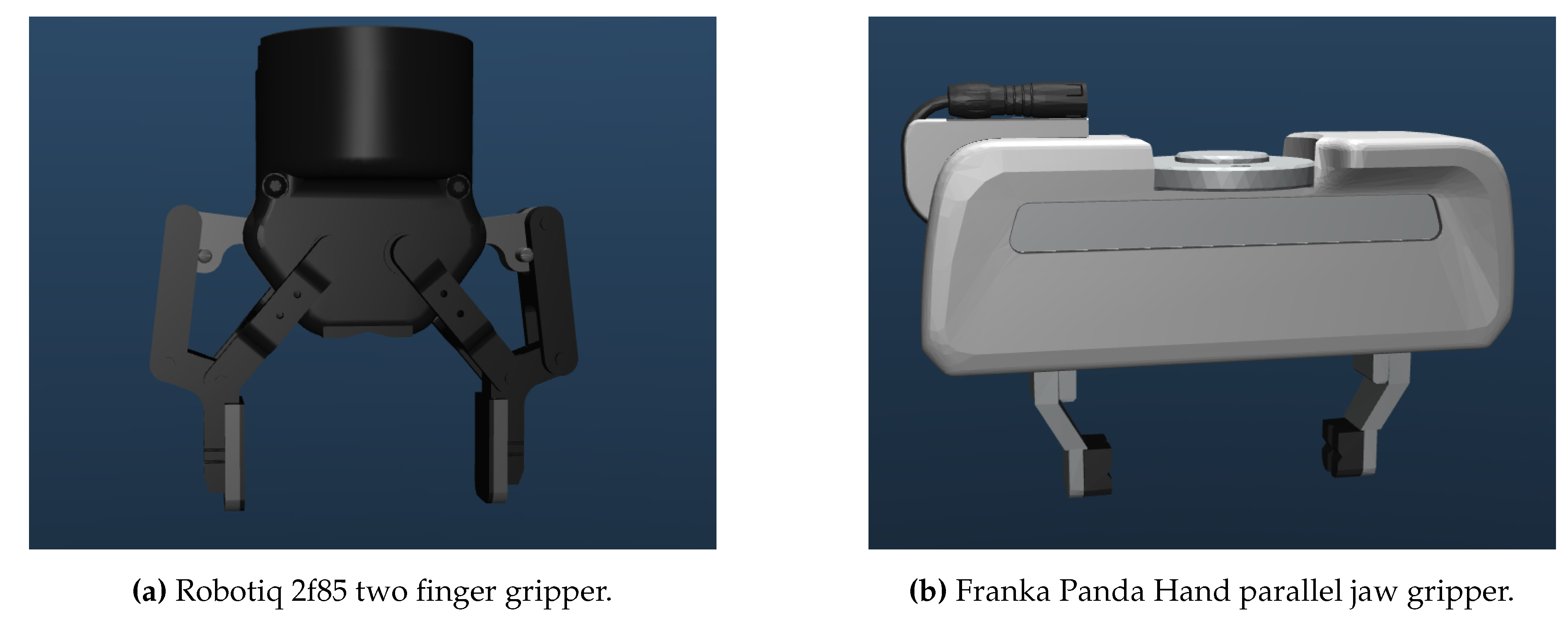
Scaling the simulation to validate new objects is straightforward. The simulation’s key configuration parameters, such as the object to use, are defined in a JSON file. Before starting the simulation, the system checks if the object has been previously subdivided, doing it if necessary. When the object is successfully subdivided, the system creates a MJCF file, the XML file MuJoCo uses to model the scene, associated to said object and using the newly subdivided meshes. Then, the system reads what gripper is going to be used to generate the grasps and includes said gripper into the object’s XML, as MuJoCo works only with one XML, one that describes the whole scene. Of course, to include the gripper into the scene’s MJCF, the gripper must be correctly modelled and it’s MJCF generated. Regarding pre-generated grippers, we tried the system with a Robotiq 2f85 and a Franka Panda Hand (see
Figure 4), both publicly available at the MuJoCo menagerie
4, the collection of robots and end-effectors curated by Google DeepMind. Though, a couple modifications have been made to the original designs:
All tools have been oriented and translated in order to make their closed fingertips touch the zero of the world coordinates, as seen in
Figure 4.
Each gripper features a MuJoCo body called "g_ref" defined as a child of the base of the gripper. This is done in order to have a reference point for the gripper with a standarised name.
The grippers have had their finger actuator renamed to "finger_actuator" and the control range remapped to the 0 to 255 range in order to control it via script without the need of adapting the simulation to each actuator.
Each tool now includes an additional joint and actuator (with a standarised name) that lifts the gripper vertically 10 cm. The modeling of the joint and actuator is based on the "lift" modeled in the "Hello Robot Stretch 3", available in the menagerie as well.
Again on the topic of automatic MuJoCo scene generation, the system also checks if the selected gripper-object pair has been previously selected in order to avoid creating unnecessary XML files. Note that, contrary to other works present in bibliography [
22] we only "load" one gripper-object pair per simulation. There is no multiple concurrent workstations, mainly due to the intention of limiting the amount of concurrent contacts and the design choice of loading only one XML representing the scene, as for the MuJoCo version used in this work, 3.1.5, it does not allow natively to load additional elements to the scene once it has been loaded into memory. Thus, we iteratively validate all the poses on a single workstation.
When the MuJoCo scene is created the system loads it into the simulation and proceeds with the validation process, using one of the three available modes. Even though the validation is deeply studied in
Section 3, for the sake of clarity some information must be advanced; the validation process in the simulation is carried by a culling phase that iterates over all the candidates and evaluates them. The simulation offers 3 modes to run the validation process:
Headless Single-Thread (HST) mode: The simulation runs fully on a single thread, going as fast as that thread allows thanks to being run in headless mode. This alternative also implements the option to record videos of the validation process, useful to debug the process. The video recording function renders and saves the frames for each iteration, thus consuming RAM and computational power, and overall, reducing notably the speed of the validation process, but still achieving faster than real (FTR) times.
Headless Multi-Thread (HMT) mode: The simulation uses all the available threads in parallel. To achieve parallelisation, the system divides the list of grasp candidates into as many groups as threads the CPU has. Then, and using Python’s multiprocessing library, each group is loaded into a thread. The information of each grasp candidate is stored in a queue, and finally merged together into a single list. As this mode is used to make the validation process go as fast as possible, the parallelised culling phase does not support video generation. This mode is the go-to option for fast grasp validation, as it is the mode that achieves the fastest FTR time.
Real-Time Interactive mode: This is the only mode that runs on real-time and does not implement the video saving tool. As it runs on real-time, it is not fit to validate a vast amount of grasps. For reference, a validation of 20k grasp candidates on this mode could take a maximum of approximately 16 hours and 36 minutes. This mode should only be used for debugging purposes.
3. Validation Method
This section describes the grasp validation method, following the execution sequence, and digging deep into the metric we propose to estimate the quality of the grasps.
3.1. The Validation
The validation pipeline’s sequence is straightforward. Assuming that the node with GPD embedded is up and the ROS2 services are accessible, the simulation node is launched. This node sends the object CAD to the sampler, as well as the information of the gripper, and the sampler returns the grasping candidates. The candidates are then validated using the preferred validation method, chosen among headless multi-thread, headless single-thread or real-time interactive. When the simulation is loaded, it starts with the culling phase. The system generates the gripper always in vertical pose, and the piece in the candidate pose, "freezing" the piece in the position. Then, the fingers are closed
5. After a defined number of steps, the piece is "freed" and the poses start being saved. The culling process has four different outcomes:
Falling: The piece falls. In this case, the iteration is terminated the moment the piece moves certain distance away from the gripper, and the score assigned to this candidate is 0.
Bad grasp: The candidate does not fall, but the movement inside the piece is high enough to score a bad grasp quality estimation. In this case the grasp is culled from the candidates.
Good grasp: The candidate was good enough not only not to fall, but also to achieve better score than the threshold.
Discovery grasp: During the development of the system, we observed that there where some grasps that started with a lot of movement, but ended completely still and stable. For example, if we pick a rectangle from the side, with a certain amount of inclination, the rectangle will rotate to be parallel to the gripper. The initial grasp was incorrect, but, if we consider this pose as a grasp, it is actually good. To search for these cases, we also calculate the score of the object taking into account only the poses starting from the half of the operative. We also define a more strict score threshold to this score. If the grasp is good enough, we record the pose of the object with respect to the gripper in the last step and add it to the list of grasps that passed the culling phase.
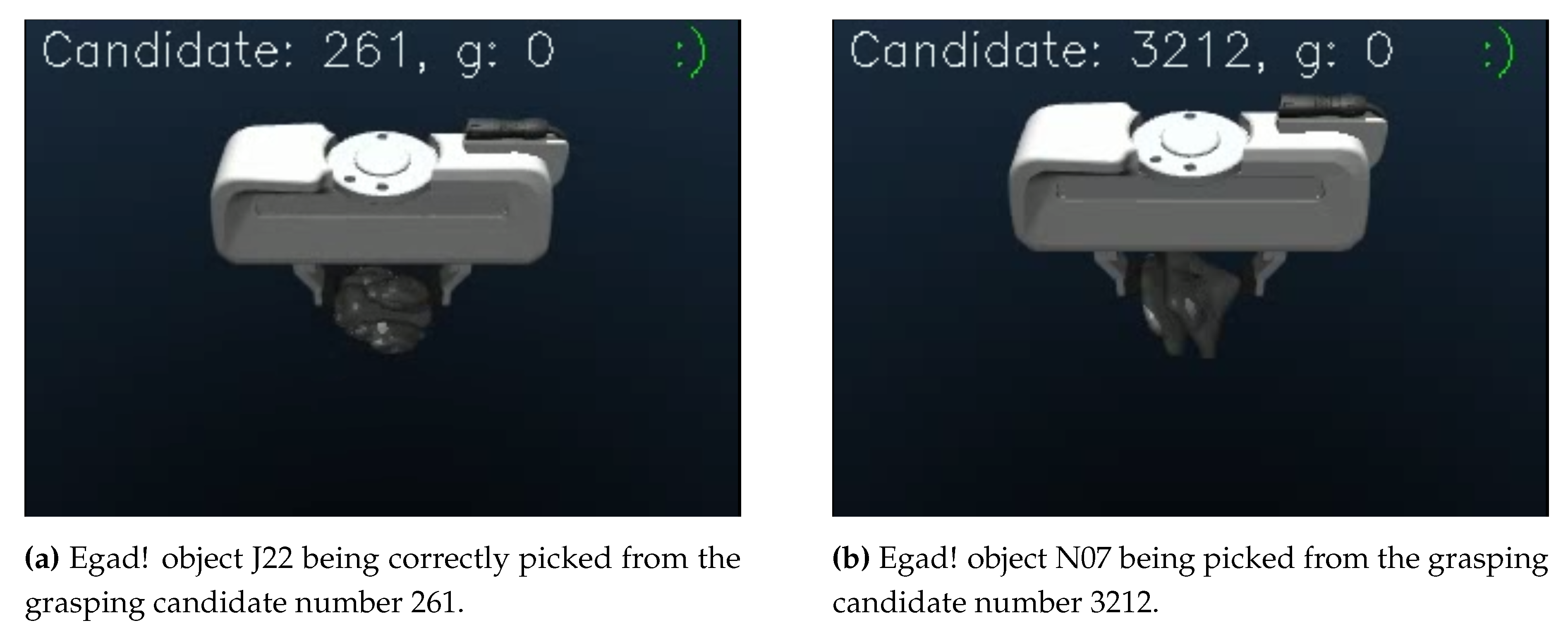
An example of a correct grasps are depicted in
Figure 5, where both attempts are correct, while on
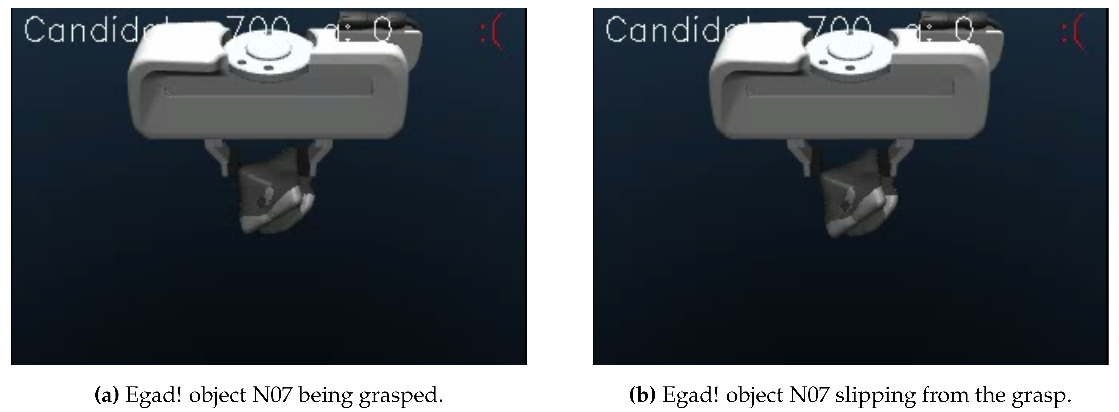
Figure 6 an incorrect attempt is presented, due to the rotation of the piece, underlining the importance of a movement-based metric, as the one presented in this work.
3.2. The Metric
Bibliography has shown the lack of a standarised metric to measure the quality of a grasp. Our proposed method offers a continuous value to portray the quality of a grasp by analysing the movement of the piece once it has been grasped, using the pose of the object during the grasping process. Thus, this approach is applicable to all state of the art simulators, and offers fine grained information of the quality of the grasp, let it be the translation of the piece as well as the rotation.
The main objective of the metric is to give a continuous value, that measures the rotation and translation of the piece during the grasping operative, not limited to initial and final pose comparison, as this does not take into account all the movement the piece makes during the grasp. With the later approach, if the piece moves during the grasp, but ends in a pose similar to the initial pose, the result would be a good score, far from reality.
The metric depicts the grasp quality in the form of a score, shown in Equation
1, and consists on the weighted sum of the translation and rotation partial scores.
Where:
: Is the weight applied to the rotation score, bounded between 0 and 1 inclusive.
: Is the score calculated for the translation.
: Is the weight applied to the rotation score bounded between 0 and 1 inclusive.
: Is the score calculated for the rotation.
The translational score is measured by obtaining the euclidean distance between the positions of two consecutive grasping poses. Then the mean is obtained from the sum, see Equation
2, to finally obtain the inverse of the value normalised applying min-max normalisation between certain thresholds, see Equation
3. Both for the rotation and the translation, the lower bound for the normalisation is 0.
: The mean translation between all the consecutive recorded poses.
and : Two consecutive vectors that contains the euclidean coordinates of the grasp pose.
n: The number of poses stored.
The rotation score is obtained by measuring the distance
6 between the quaternions of two consecutive poses. Then, the distance is calculated for each consecutive pair of poses, the sum and mean are calculated, see Equation
4 and finally the value is min-max normalised following the same logic as with the translation score, this is, obtaining the inverse of the min-max normalisation, see Equation
5.
: Mean of orientation distances between al consecutive recorded quaternions.
and : Two consecutive quaternions storing the rotational information of their respective grasp pose.
n: The number of poses stored.
The weights given to the rotation and translation scores, and respectively, can be modified in order to give more importance to the rotation or translation, depending on the context. The reason why we take the inverse of the min-max normalisations is that, the lower the movement, the higher the score should be. The score does not measure how much the objects move, but how much the object does not move.
Thus, to obtain each pose, we access the pose information MuJoCo provides, calculate the pose respect to the gripper, and store it every 50 simulation steps. This metric can be implemented in other simulation environments given that the information of the pieces’ pose is accessible. It must be noted that the thresholds that measure the upper bounds of the maximum rotation and translation, this is, and , could be modified in order to allow more or less motion.
4. Experimentation
The main scope of this work has been the development and evaluation of a self-supervised model-based grasp pose estimator based on the MuJoCo physics engine. To assess the adequateness of the approach, it must be validated both in terms of time employed to obtain the grasps, as well as the quality of the grasps themselves. To this end, we compared and studied the grasps and their distribution over the objects, analysed the time-grasp relation and finally validated the grasps in a real robotic system. Most importantly, we compared out approach to the most similar state-of-the-art approach, this is, MultiGripperGrasp [
22].
This section presents both the resources and the experiments employed to carry out the fitness assessment process. Thus, it has been divided in 4 parts:
Section 4.1 gives a brief overview of MultiGripperGrasp, the system we are comparing with.
Section 4.2 shows the objects used to estimate the grasping points.
Section 4.3 describes the modeling of the experiments.
Section 4.4 showcases the hardware used, both regarding the robotic system and the computers.
4.1. MultiGripperGrasp
MultiGripperGrasp, from now on MGG also features a two stage system: a sampling algorithm and a validation process in simulation. The sampling step is carried out in GraspIt! [
27] and the initial candidate evaluation requires IsaacSim [
28]. Noteworthily, the user must manually bridge the output of GraspIt! as input to IsaacSim to be validated since these two components are not communicated. Note that objects need to be modeled twice, once for GraspIt! and a second time for the IsaacSim input (they provide a tool to prepare the objects for GraspIt!). To model the objects used in the experimentation, we followed the approach proposed in the paper [
22], assuming uniform density of 100 and friction of 0.5 for all objects. Most importantly, IsaacSim requires a high-end computer to be able to run. For instance, the minimum requirements to be able to run IsaacSim, presented in the Nvidia Omniverse Documentation web
7 are a quad core Intel Core i7 (7th generation) processor, 32GB of RAM, 50GB SSD storage, a GeForce RTX 3070 with 8GB
8 of VRAM and Ubuntu 20.04/22.04 or Windows 10/11. Regarding GraspIt!, MGG provides a docker image containing GraspIt! on a Python2 environment and on Ubuntu 18.04.
4.2. The Objects
Egad! [
30] is a dataset consisting on over 2000 objects procedurally generated using evolutionary algorithms. The objective of this dataset is to offer a publicly available, open source benchmarking tool in order to train and evaluate robotic systems, both in grasping tasks and in perception tasks. Most notably, this diverse dataset categorises the objects depending on the complexity of the shape of the object, and the difficulty to grasp each object. This categorisation is portrayed in the names of the objects; the names are coded with one letter and a number, where the letter refers to the grasp difficulty and the number to the shape complexity. They compared their dataset to other very popular choices within the robotics community: YCB [
26] dataset and Dex-Net 2.0 [
31] dataset, finding that their proposed dataset covers more different geometric shapes and has more objects. Most importantly, they make public their object models, thus being able to download and even print them to test them in a real robotic system, while YCB and Dex-Net rely on the availability of the real objects, having references near impossible to find in non US countries. Finally, they also offer a tool to scale the objects of the dataset in order to allow them to fit in the grippers.
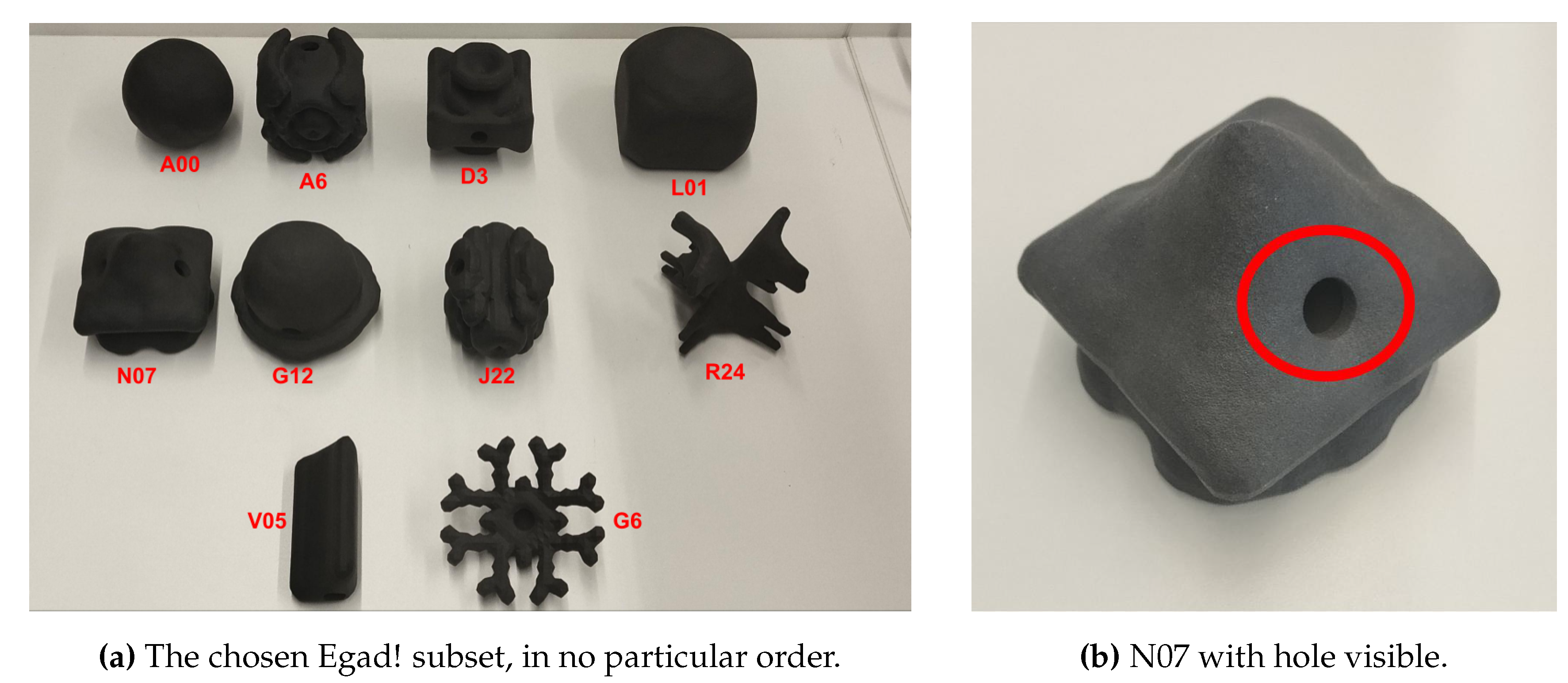
For our experimentation we found Egad! to be a great object dataset, as we could test in the real robotic system the objects, and we also had a guide that defined the graspability of the objects. Taking this graspability and complexity metrics, we took a subset of 10 objects trying to cover the complexity and graspability of the objects as best as possible. Our sub-set is formed by objects from their train and test sets. From the train set we have chosen A00, L01, N07, G12, J22, R24 and V05, and from the test set we have taken A6, D3 and G6. Note that in order to print them, we had to create a hollow version of each one of those objects by opening holes of 10 mm (see
Figure 7). The width of the walls is left to 4 mm. The printing material used is Nylon 12, which offers a robust surface and enough strength to not be deformed by the grasps.
4.3. Modeling the Experiments
It is important to note that, the grasp estimation has been done using a Franka Panda Hand. This is mainly because, as for the date of this work, MGG does not include the Robotiq 2f85 gripper in their system. For that reason, we proceeded to carry out the experiments using the Franka Panda Hand, available in Isaac Sim, GraspIt! and MuJoCo.
To carry out the experiments, we launched both our system and MGG, obtained the grasping points for the same Egad! objects, using the hollowed STLs, randomly sampled 10 grasps for each object, modified the output in order to be used as input in our application to carry the picking operatives, and analysed the grasps both in terms of grasp accuracy in the real robot and mathematically to determine qualities such as centering and grasp sparsity. To conduct this analysis, the following experiments are proposed:
Validation at the real system: The most important part is to evaluate the quality of the grasps based on the capability of the robot to pick the objects from that point. To validate the grasps we have used the Robotiq 2f85 two finger gripper, due to the lack of availability of a Franka Panda Hand. To carry out the validation, our system did not require any kind of adjustment, as we estimate the grasps with respect to the grippers closed fingertips, but we took into account the difference between the dimensions of the Robotiq 2f85 and the Franka Panda Hand in order to validate correctly MGG, and modified the grasping points in order to apply this difference. This transformation is required as the validation application estimates the grasping point with respect to the tip of the fingers, while MGG returns the pose with respect to the gripper base. The grasping points have not been further modified. Then, we programmed in the UR10 a script that given an object, finds that object in the scene and picks the object from the defined grasping point. As validating each proposed grasping point for each object is not viable, we randomly sampled 10 grasps for each object and carried out this validation for each one of those grasps. Note-worthily, regarding the sampling process on the MGG dataset, we only sampled 10 grasps from the grasps that where hold more or equal to 3 seconds, this is, their theoretic best grasps. This adds up to 200 grasps in total, a hundred from each approach. As both systems estimated the grasping poses for the objects when they where isolated, if the robot could not find a collision-free trajectory to the object due to it colliding with the table, we helped the robot by elevating the object and thus isolating it from the environment. The experiment itself is straightforward; the robot goes to the defined grasping pose and lifts it, holding it in place for 3 seconds. Then, evaluate if the piece has been correctly picked or not, marking as successful only the grasps that manage to stay in grasp during the 3 second period.
Comparison with manually defined grasps: We also compare the grasps obtained from both methods with a ground truth in the form of manually defined grasps to try to quantify how much distance would there be between the ground truth and the systems’ outputs, as we argue that the grasps defined manually by the operators tend to be near-optimal grasps for each object, as they are validated on the spot. Adding to that, the manually defined grasps cover the entire graspable area of the object. Thus, comparing the obtained grasps with the ground truth will also tell the sparsity of the grasps proposed by the system.
Grasp centering: We measure if the grasps are actually centered on the piece (see
Section 5.3), as in some applications it is critical that the grasp is centered on the object, not to hit nor move the objects besides the one that is going to be picked.
Time per grasp: We analyse the system in order to measure how much time is needed to obtain a valid grasp.
4.4. Hardware
The experiments have been performed in two different computers. Computer one counts with 16 GB of RAM, an Intel Core i7-10700 CPU 2.90GHz × 16, no dedicated GPU and Ubuntu 22.04. This PC has been used to run our whole system and to run MGG’s sampling part (The GraspIt! docker).
MGG’s initial candidate validation using IsaacSim has been carried out on a computer with 64 GB of RAM, an Intel Core i7-12700KF x 20, a Nvidia RTX 4070 12GB with Ubuntu 22.04.
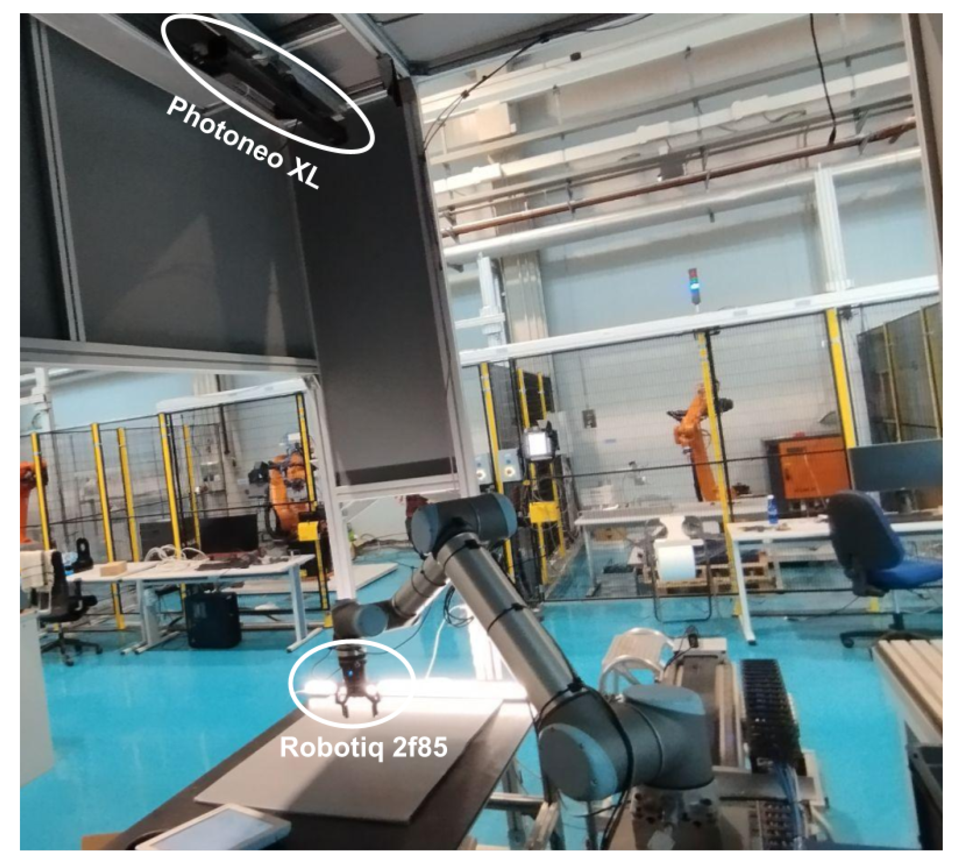
The validation in the real system has been executed using an UR10 arm with a Robotiq 2f85 parallel jaw gripper, combined with a stationary Photoneo XL camera set above the workspace to carry out the object pose estimation. The setup, with the aforementioned elements, can be seen in
Figure 8.
5. Results
This section is divided into 3 main parts.
Section 5.1 gathers the results obtained during the validation in the real robot, while
Section 5.2 contains the comparison with the ground truth grasps.
Section 5.3 analyses the centering of the grasps.
5.1. Real Robot Validation
During the validation process, we observed that due to the off-centering of certain grasps, some pieces moved notably when the pads where closing, thus affecting the grasping points themselves. Hence, we labeled those grasps as failed grasps, as the object was not picked where the system intended.
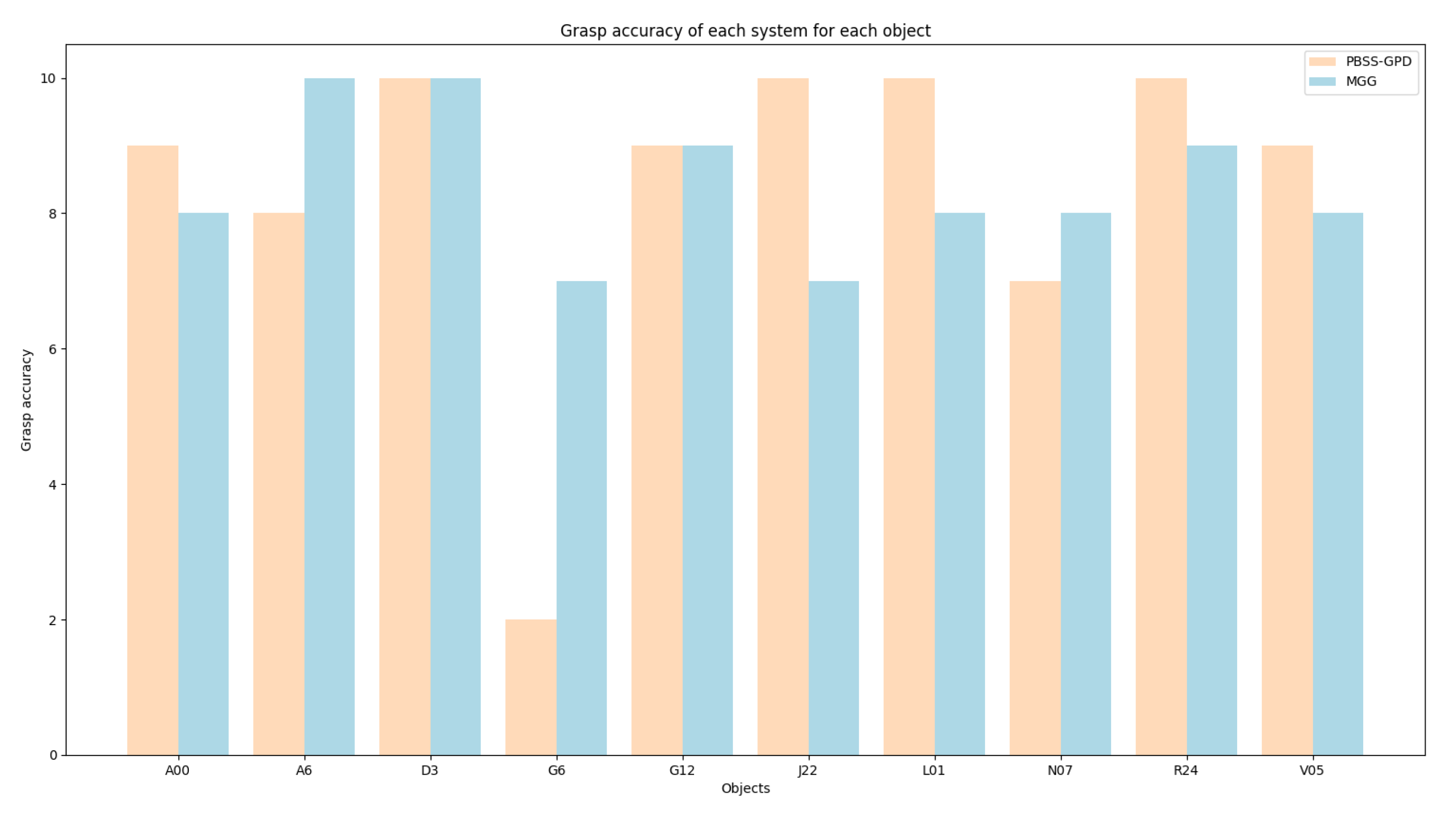
Figure 9 shows a graph containing the grasps that where successful, in the sense that the piece was lifted from the table and did not fall during the grasp. It can be seen that both systems performed the same regarding accuracy and that both had quite consistent grasp accuracy for all objects, excluding G6 in our system, that performed specially poorly and lowered the overall mean. The validation process of that object showed that one of the best ways to pick the object was from the outter perimeter, a recurrent grasp in MGG, thus achieving a higher score. Furthermore, our system also performs worse in A6, altough we achieve better results in J22 and L01, but the difference is not as notable as in G6.
Most notably, during the validation process, we also observed that MGG returned two grasps where the gripper collided with objects (A6 and V05) themselves. These two are the only instances present in the sampled population.
Finally, regarding the object positioning, due to the fact that we wanted to evaluate the accuracy of the systems estimating grasps, and that both systems calculate the grasps when the object is in the air, to avoid potential collisions of the robot with the table we used a small platform to put the pieces on. This accuracy does not portray the ability of the systems to generate grasps that are fit to take the object from the table, but it measures the quality of the grasps themselves instead. This is also why it may seem that there is no correlation between the theoretic complexity of each piece with the grasp accuracy of the systems. The analysis of the complexity of the pieces should be carried out when trying to grasp the object from the table, without any help.
5.2. Similarity with Real World Grasps
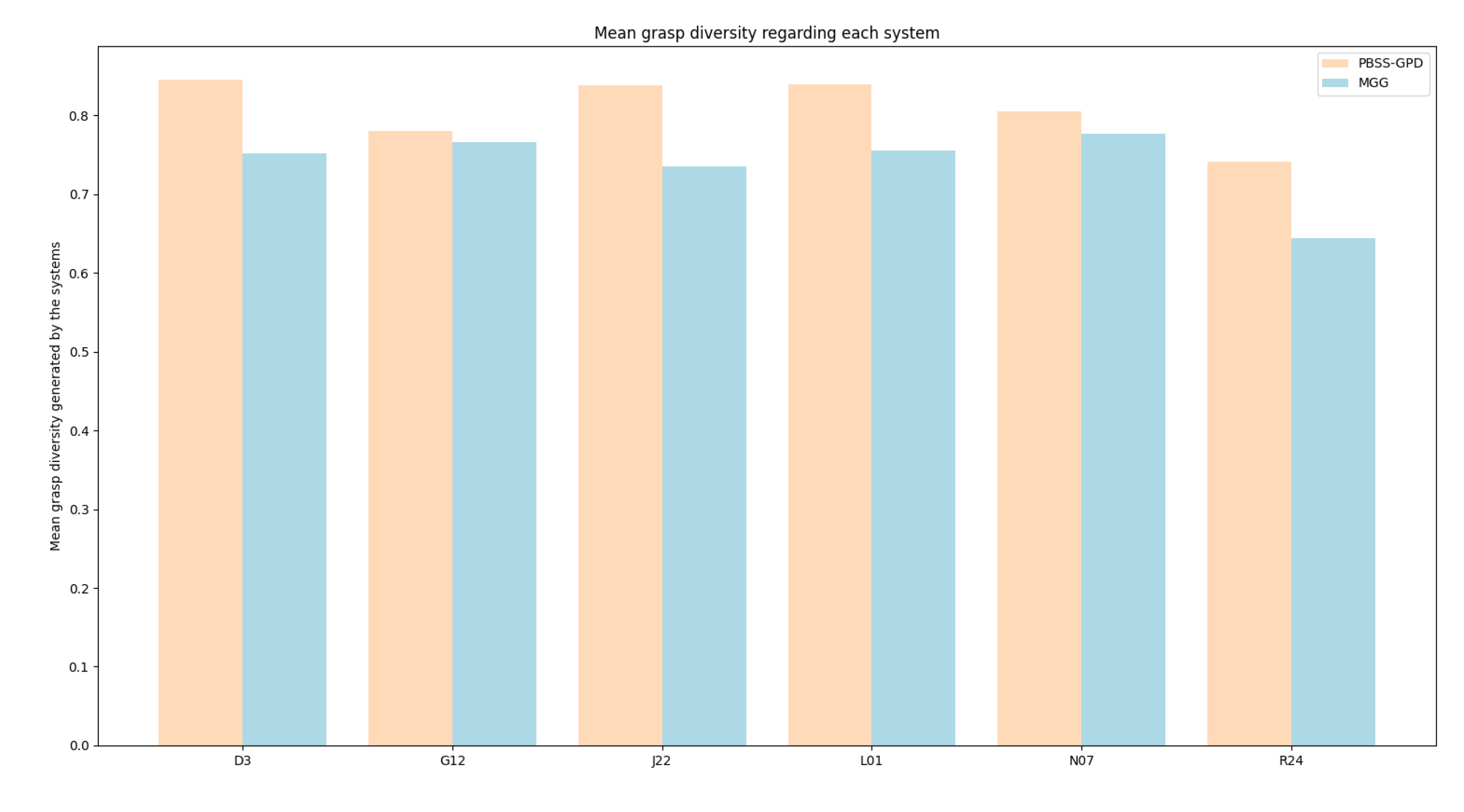
We manually defined a set of grasps that cover the graspable area of the object, for a random subset of different objects in order to estimate if the systems return grasps that are similar to the poses an expert would define, this is, high quality grasps that are scattered trough the object. Then, for each of these manually defined grasps, we searched in the successful candidates returned by the system i.e. the candidates that resulted on a successful grasp in the real robot experiment, the most similar grasp and stored the similarity between that grasp and the manually defined grasp. We then calculated the mean similarity for each object, obtaining the results shown in
Figure 10.
The results show an overall slightly better results of our system. Most precisely, the amount of grasps correctly estimated by each system play a crucial role in this statistic, as a higher number of correct grasps may improve the probabilities of having a grasp similar to one manually proposed. Taking that into account, our system achieves an overall mean similarity of 0.808807 while theirs achieve a mean of 0.738469. This means that our system returns grasps that are scattered through the object and that are similar to the ones manually defined.
The similarity is calculated using the following formula:
Where:
S: The similarity between two grasps.
: The weight given to the displacement or translation similarity. In this case it is 0.7.
: The weight assigned to the rotational similarity. In this case is set to 0.3.
: The translation distance between two poses. Calculated using the euclidean distance.
: The maximum euclidean distance two poses can have. In this case is 8 cm (the maximum size an object can have).
: The rotational distance between two poses. It compares two quaternions
9, taking a value between 0 and 1, where 0 is the same quaternion and 1 the adverse.
5.3. Grasp Centering
The estimation of the centering of the pieces can be used to measure the quality of the grasp, as it is undesirable for a grasp to drag the piece. This dragging can not only cause damage to the piece, but also modify the original grasping point. Although, it must be taken into account that the centering of the grasp does not always translate into a successful grasp. Noteworthily, it is also harder to use off-centered grasps to plan trajectories, as the gripper may collide with other near objects when trying to perform the grasp. Thus, we argue that, for most cases, a centered grasp is preferred to an off-centered grasp, even more if the off-center is due to miscalculations.
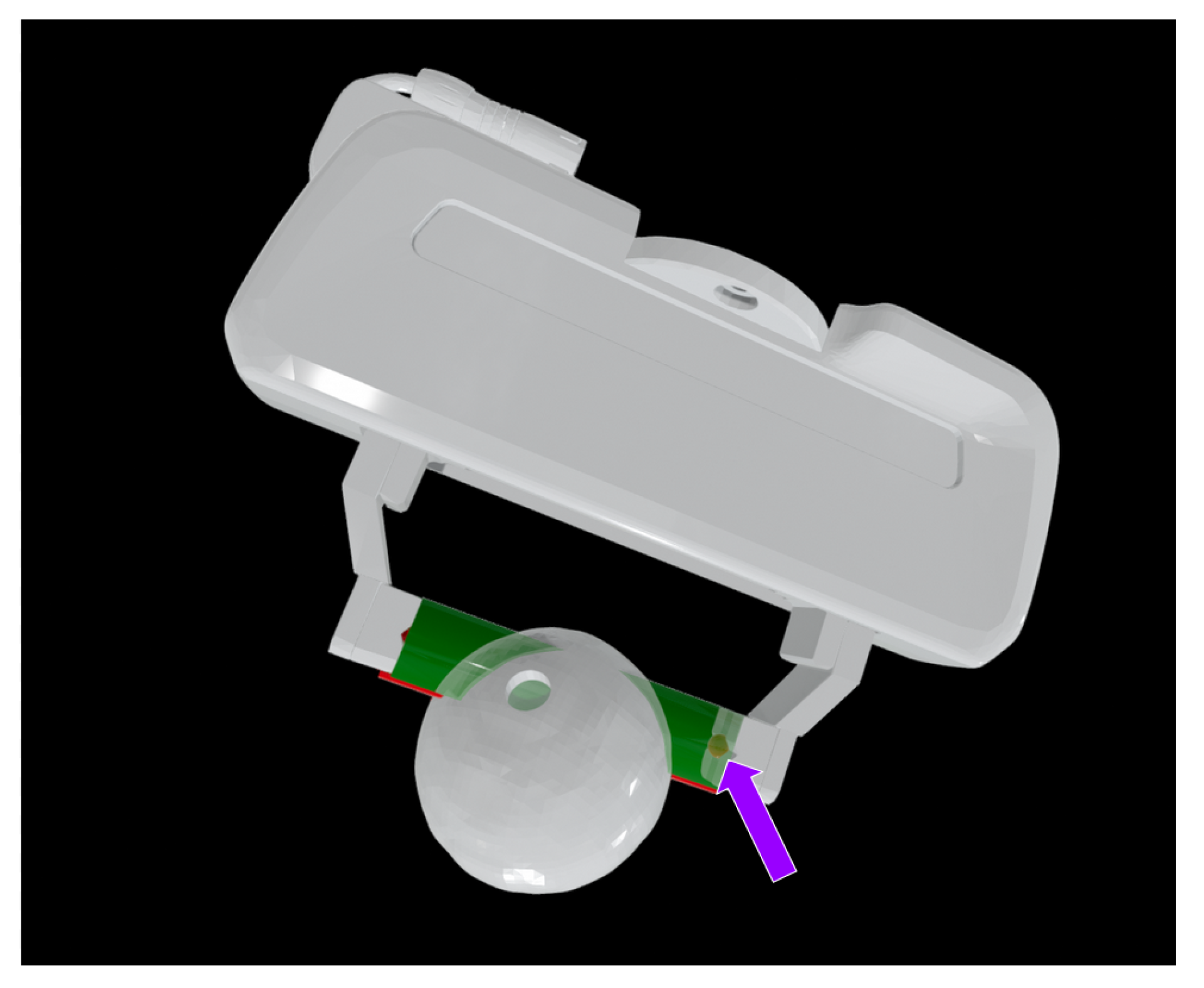
To measure the centering of a grasp we created a bounding box mimicking the trajectory the Panda’s pads would follow, and calculated the nearest point from the sides of the bounding box to the volume of the piece within this bounding box, as seen in
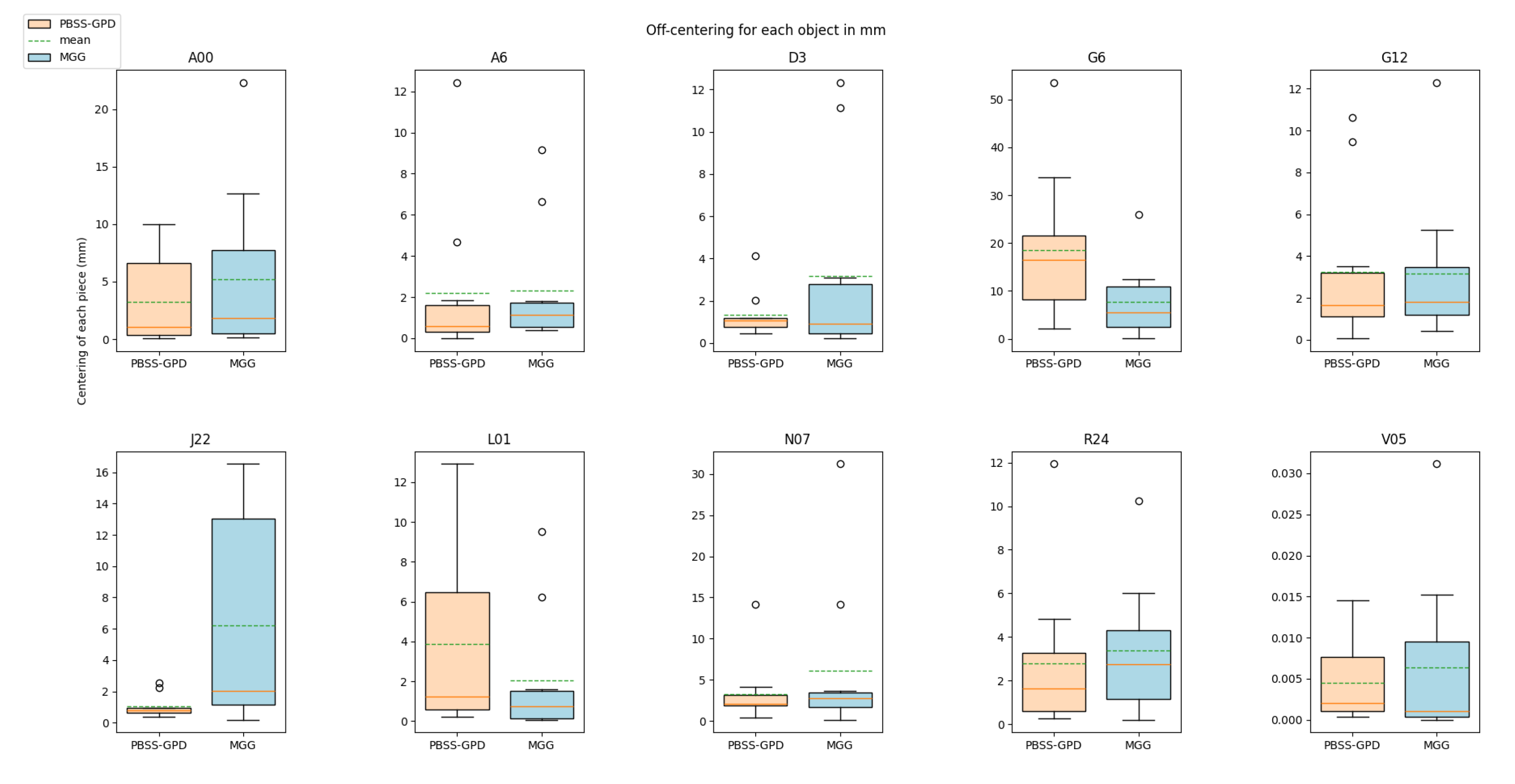
Figure 11. Then, we calculate the absolute value of the difference of the distance from both sides of the bounding box to the object. This estimates the absolute value of the displacement of the piece, meaning that as the value is closer to 0, the piece is more centered between the pads. We carried out this process for each object, using all the grasps employed to validate the object with the real robot, observable in
Figure 12. Taking the mean off-centering for each object, we calculated the mean and quantified how much off-centering does both system produce.
Our system produced a mean off-centering of 4.402 mm, while MGG produced a mean off-centering of 4.574 mm. Moreover, the grasp centering is very similar for each objects, excluding some outliers like J22 where MMG performed worse or G6 and L01 where our system performed badly.
5.3.1. Time per Grasp
Each system estimates the grasps with different design and implementation approaches; MGG starts the estimation process for all objects in parallel
10, while our approach goes sequentially. Furthermore, MGG requires to set a minimum amount of GraspIt! "plans" for the system to achieve (and it will evaluate plans until that amount is achieved) while our system only requires to set an initial amount of samples and orientations to estimate.
Taking that into account, we calculated the time required to estimate a valid grasp. In the case of MGG, we took the time spent from the start of the grasp sampling to the end of the validation in Isaac Sim and divide it by the amount of grasps that achieved a 3 second grasp in their simulation. For PBSS-GPD, we divided the time from the start of the sampling process to the end of the MuJoCo simulation validation, by the amount of grasps that the simulation considered fit, i.e. the grasps that surpassed the quality threshold.
Table 1 gathers the number of grasp of each system as well as the time employed to obtain those grasps. Checking the time per grasp, we can see that our system obtains the grasps nearly 18 times faster (17.7350), most probably due to the use of GPD instead of GraspIt!.
6. Conclusions and Further Work
This work presents PBSS-GPD, a fully automatic system that given a CAD model generates grasping poses for the object. The system has not only proven it’s fitness in terms of transferability to the real world, but it has also being compared to a contemporary approach in terms of accuracy, grasp centering, similarity with real world grasps and time per grasp, showing similar to small improvements in the formers and an important advancement in the latter. Moreover, the system runs completely on CPU.
Hence, for the sake of clarity we present the key compared elements between our systems:
Summing up, both systems excelled in terms of accuracy, achieving the same amount of correct real world grasps. From the 100 samples obtained from each system, 84 where correct in both cases, thus obtaining an accuracy of 84%. Regarding the time per grasp, the time required for each system to obtain a valid grasp has been measured. While MGG obtains 2.637 second per grasp, our system obtains a valid grasp in 0.149 seconds, approximately 18 times faster. This directly translates in more data generated in a certain amount of time, making it a desirable feature in order to train learning based algorithms, as the amount of data they need is vast. Moreover, both systems estimate fairly centered grasp poses, an aspect critical to grasp objects without moving them in the workspace. Our approach achieved a mean off-centering of 4.402 mm, while MGG generated grasps with a mean off-centering of 4.574 mm. Thus, our method does not improve show a significant improvement in this aspect compared to MGG. The grasps generated by both systems show good similarity with the ground truth for the random subset of objects. In terms of strict similarity values, our system achieves a score of 0.8088 while theirs achieve a score of 0.7385. Thus, we can infer that our system generates grasps more akin to the ones generated in the real world, and hence covering the object better. Most notably, our system is specially less restrictive in terms of minimum system requirements, mostly because it runs completely on CPU. In terms of usability, MGG isolates the grasp candidate sampler and simulation-based grasp validator. This makes the whole validation pipeline sub-optimal from the point of view of usability [
32], as the user must collect, modify and export the data from the sampler in the docker to the validator, outside of the docker. Regarding our system, the communication via ROS2 services has proven to be useful in order to communicate the two processes, even if our sampler is embedded in a docker. Finally, MGG provides more grippers off-the-box, as well as support for dexterous hand grasp pose generation. Adding to that, both systems offer the ability to scale the simulation by manually adding new grippers and objects. While regarding the grippers, it is true that for both systems the grippers must be manually modeled, in terms of objects our system scales better, as the only thing necessary is the OBJ file. Our approach generates the necessary subdivision, physical properties and MuJoCo files automatically, while MGG requires the user to model the objects in Isaac Sim.
Regarding the next steps, the work presented in this manuscript could be improved exploring different approaches to enhance the initial GPD candidate quality using the information provided by the CAD model. Regarding the simulation environment, we plan to carry out a parameter optimisation process using evolutive algorithms with the objective of reducing the "sim2real" gap, as bibliography [
33] has shown the viability of this approach. Moreover, we plan to extend our system to a greater number of grippers and tools, covering the range of two-finger parallel grippers, three-finger parallel grippers, suction tools and magnetic tools, as well as to include and optimise the MuJoCo parameters for a greater amount of available object materials.
Public Involvement Statement:No public involvement in any aspect of this research.
Author Contributions
Conceptualization, A.I., I.M. and A.A.; methodology, A.I., J.A.R., I.M. and A.A.; software, A.I. and J.A.R.; validation, A.I. and J.A.R.; formal analysis, J.A.R.; investigation, A.I. and J.A.R.; resources, A.I., I.M. and E.L.; data curation, A.I., J.A.R. and E.L.; writing—original draft preparation, J.A.R.; writing—review and editing, A.I. and E.L.; visualization, A.I., J.A.R and E.L; supervision, I.M., A.A., A.I., E.L.; project administration, I.M.; funding acquisition, A.I., I.M and A.A. All authors have read and agreed to the published version of the manuscript.
Figure 1.
Diagram showcasing the system architecture. Two parts are differentiated, the GPD initial grasp candidate estimation part and the MuJoCo realistic simulation grasp validator part.
Figure 1.
Diagram showcasing the system architecture. Two parts are differentiated, the GPD initial grasp candidate estimation part and the MuJoCo realistic simulation grasp validator part.
Figure 2.
Example of the output of GPD. Here, the pointcloud of the piece as well as the representation of the gripper for each candidate is presented. GPD evaluates the geometrical viability of the grasps from a variety of orientations.
Figure 2.
Example of the output of GPD. Here, the pointcloud of the piece as well as the representation of the gripper for each candidate is presented. GPD evaluates the geometrical viability of the grasps from a variety of orientations.
Figure 3.
Convex hull vs convex decomposition using CoACD. Sub-
Figure 3 shows that using the convex hull is not a viable way to estimating realistic contacts. On the contrary, decomposing the geometry using CoACD as seen in Sub-
Figure 3 allows the system to perform more realistic contacts.
Figure 3.
Convex hull vs convex decomposition using CoACD. Sub-
Figure 3 shows that using the convex hull is not a viable way to estimating realistic contacts. On the contrary, decomposing the geometry using CoACD as seen in Sub-
Figure 3 allows the system to perform more realistic contacts.
Figure 4.
The models obtained from the MuJoCo menagerie and modified to integrate them into our validation process. The orientation of the gripper is shown as the Z axis going from the fingertips to the base, and the X axis parallel to the horizontal plane of the gripper.
Figure 4.
The models obtained from the MuJoCo menagerie and modified to integrate them into our validation process. The orientation of the gripper is shown as the Z axis going from the fingertips to the base, and the X axis parallel to the horizontal plane of the gripper.
Figure 5.
Two examples of Egad! pieces being grasped. The picture show the gripper, the piece and certain information; the candidate ID, the used gravity ID and a color code to help debug if the grasp was correct. Green means correct, red means incorrect and yellow means discovered grasp.
Figure 5.
Two examples of Egad! pieces being grasped. The picture show the gripper, the piece and certain information; the candidate ID, the used gravity ID and a color code to help debug if the grasp was correct. Green means correct, red means incorrect and yellow means discovered grasp.
Figure 6.
This figure showcases two instances of the same grasp attempt, candidate 700. The leftmost image, Sub-
Figure 6 shows the piece at the starting moments of the grasp. The image to the right, Sub-
Figure 6, shows the same attempt some moments later. There is a small rotation made by the piece, most notably on the left fingerpad of the Panda Hand.
Figure 7.
Egad! objects chosen in our subset, presented in no particular order in Sub-
Figure 7. The sub-set covers the graspability and geometric complexity spectrum. Sub-
Figure 7 shows the 10 holes made in the objects in order to hollow them. The walls are 4 mm thick.
Figure 7.
Egad! objects chosen in our subset, presented in no particular order in Sub-
Figure 7. The sub-set covers the graspability and geometric complexity spectrum. Sub-
Figure 7 shows the 10 holes made in the objects in order to hollow them. The walls are 4 mm thick.
Figure 8.
Setup of the real robot system, featuring an UR10, Robotiq 2f85 gripper and a Photoneo XL to locate the pieces.
Figure 8.
Setup of the real robot system, featuring an UR10, Robotiq 2f85 gripper and a Photoneo XL to locate the pieces.
Figure 9.
Accuracy of the methods. This graph studies the percentage of successful grasps without taking into account the ones that moved largely during the grasp. Both approaches achieve a remarkable 84% accuracy.
Figure 9.
Accuracy of the methods. This graph studies the percentage of successful grasps without taking into account the ones that moved largely during the grasp. Both approaches achieve a remarkable 84% accuracy.
Figure 10.
Object-wise mean grasp similarity. It quantifies how similar the grasps are compared to a manually defined ground truth. It is useful to quantify the similarity to the ground truth for the grasps estimated by the system, assuming that the ones manually defined have the highest quality. Our system creates grasps more similar to the ones manually defined for all the objects of the subset compared to the ones MGG provides.
Figure 11.
Approach used to measure the centering of the grasp. The nearest point of the volume of the piece within the green bounding box to the red bubbles is calculated. There is one red bubble on each side of the bounding box. Thus we can estimate if the grasp is off-centered, meaning that a side would collide with the pad earlier than the other.
Figure 12.
Box plots showing the off-centering data obtained from the grasps used to carry out the validation process in the real system (10 for each object).
Figure 12.
Box plots showing the off-centering data obtained from the grasps used to carry out the validation process in the real system (10 for each object).
Table 1.
Table showing the fit grasp number as well as the time used to obtained those grasps and the time per grasp. Our system performs almost 18 times faster.
Table 1.
Table showing the fit grasp number as well as the time used to obtained those grasps and the time per grasp. Our system performs almost 18 times faster.
| |
Grasp # |
Time (s) |
Time per grasp |
| MGG |
8712 |
22970 |
2.6372 s/grasp |
| Ours |
10180 |
1514 |
0.1487 s/grasp |
