1. Introduction
In the present era, cochlear implantation has become a widely accessible method of rehabilitating patients with profound sensorineural hearing loss. The indications for treatment with this method are constantly evolving, and the indications are subject to change. This is due to the introduction of increasingly sophisticated technology in cochlear implants and the expansion of knowledge about electrophysiology, which has led to advances in surgical procedures. A cochlear implant (CI) is an electronic prosthesis for hearing those functions by capturing sounds from the surrounding environment and transforming them into electrical impulses, which are then conveyed by an electrode placed in the cochlea to the ends of the auditory nerve. The placement of the electrode in close proximity to the cochlear nerve allows for more precise stimulation due to the proximity to the nerve endings. Additionally, this configuration reduces energy consumption [
1]. The application of a thin, delicate perimodiolar electrode, exemplified by the Cochlear 532/632 model, allows for a potentially close positioning to the modiolus [
2], while simultaneously preserving residual hearing and facilitating localization within the scala tympani [
2,
3]. However, as demonstrated in other studies, the use of perimodiolar electrodes is more often associated with the risk of tip fold over (TFO), which occurs when the electrode tip folds over the cochlear wall. The incidence of tip fold over (TFO) for the Cochlear CI512/612 (Contour Advance - CA) electrode is 0.05%, while for the Cochlear CI532/632 (Slim Modiolar – SM) electrode, may be as high as 10% [
4]. An electrode bend within the cochlea may result in worsening of speech discrimination or facial nerve stimulation [
5]. For this reason, great importance is attached to the possibility of intraoperative diagnosis of this complication and the appropriate intervention, namely electrode reinsertion. In order to achieve the aforementioned objective, it is essential to prioritize the potential for intraoperative diagnosis and the subsequent appropriate intervention, which may entail re-insersion of the electrode.
To assess the appropriate course of insertion and the placement of the electrode within the cochlea, one may utilize radiological examinations in the form of fluoroscopy [
6], conventional radiography, or cone beam computed tomography [
2]. The application of CT or RTG scans intraoperatively is associated with several disadvantages, including the need for space, equipment, and personnel who are not accustomed to working in surgical settings. Furthermore, radiological examinations expose patients, frequently children, and personnel present in the operating room to ionizing radiation. The performance of intraoperative imaging studies prolongs the duration of the surgical procedure. Consequently, in certain cochlear implant centers, these studies are not feasible intraoperatively and are instead conducted only after the first or second postoperative day. Such an approach precludes the possibility of modifying the electrode placement in the event of an anomaly, thereby exposing patients to the potential risk of reoperation.
One of the parameters that can be evaluated in radiological studies is the angle of bend of the electrode, which indirectly indicates the proximity of its position to the modiolus. This fact was used in the work of Perenyi [
7], where the SM electrode was shown to be positioned closer to the modiolus than the CA. However, this test does not allow assessment of potential electrode dislocation to the scala vestibuli, which is important for the future functioning of the CI patient. In previous work, it was shown that translocation of the electrode to the scala vestibuli gives worse effects on stimulation and discrimination, and requires greater consumption of the energy [
2,
7]. It is also noteworthy that one of the areas of advancement in the field of ear implant technology is the pursuit of fully implantable devices.
One of the technological limitations is the battery's deterioration and the necessity of recharging it. Therefore, it is advisable to insert an electrode that ensures the lowest possible energy consumption. During a live surgical procedure, the surgeon implants an electrode, yet retains limited control over its subsequent trajectory within the cochlea. In order to provide the optimal conditions for the rehabilitation of a patient with CI, for an extended period, electrophysiological measurements have been conducted, relying on the assessment of electrode impedance and electrically evoked responses of the auditory nerve. However, these techniques have proven inadequate for the intraoperative detection of TFO [
5,
8]. The assumptions include the selection of an appropriate electrode, the necessity of selective stimulation, and the intraoperative assessment of electrode position. These developments have led to the advent of non-invasive electrophysiological studies, conducted in the operating room, which provide the opportunity for potential electrode correction. In this way, the aforementioned developments have paved the way for the advent of non-invasive electrophysiological investigations, conducted in the operating room, which may potentially facilitate corrective measures regarding implanted electrodes.
In their 2012 study, Vanpoucke and colleagues [
9] proposed a method for measuring electric field strength based on the differences in passive voltage between adjacent electrodes in an implant. After dividing the voltage value by the stimulating current value, the impedance (ohms) value was obtained, which varies with the distance between the stimulating and recording electrodes [
9,
10]. Based on this, a 22x22 square matrix was constructed for the Cochlear electrode with 22 contact points, which depicts the transimpedance of the electrodes in the form of a heat map [
9,
10,
11].
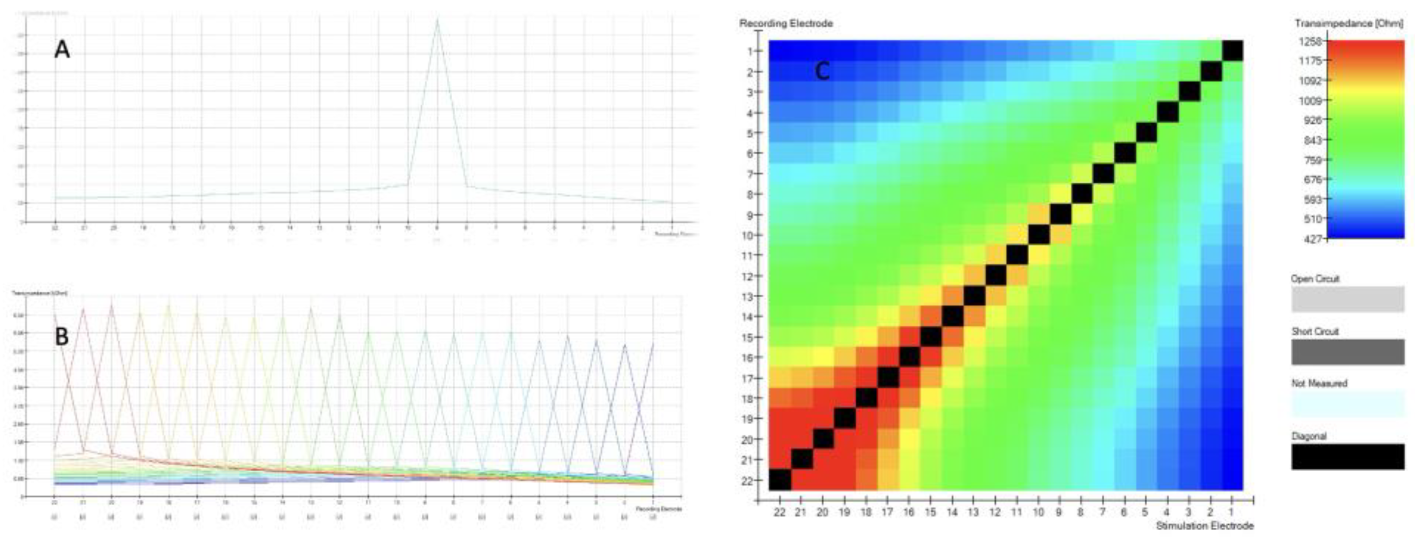
When TIM measurements are obtained, the intracochlear potential is measured along each of the 22 electrode contacts while stimulating a single contact in monopolar mode. An example of this can be seen for a single electrode in
Figure 1A and for all electrodes in
Figure 1B. With a proper insertion the recording electrode is at its maximum value, in this case, at the corresponding electrode 9 diagrammed in
Figure 1A. The voltage measured at the recording electrodes is divided by the applied current at the stimulation contact.
Figure 1 shows TIM (A, B, C) results displayed in CustomSound ® EP software suite. When a single electrode is stimulated, it generates a voltage. The voltage is measured not only at the stimulation electrode itself, but also at all the other contacts of the electrode array. The farther the distance from the stimulated electrode, the lower the voltage. This measurement is repeated for each electrode of the array and all remaining electrodes. In a simplified way, this allows to assess the electrode position within the cochlea. Furthermore, it can be graphically displayed (
Figure 1 C) as an electrode position “image” called heatmap, that can be easily assessed visually by the surgeons during the surgery.
The highest values (black boxes) are recorded at stimulating electrode and forms the diagonal with the bottom left corner of the matrix representing the apical (distal electrode 22) to the top right basal (proximal electrode 1). Open circuit is represented by light grey color, short circuit as dark grey and when we have no data, then we see light blue
The evaluation of the proper positioning of the electrode in the context of a heatmap analysis is based on a subjective assessment of colors. However, as demonstrated by Leblans, Żarowski and colleagues [
11], in certain instances, the curvature of the electrode at its apex could lead to erroneous interpretations.
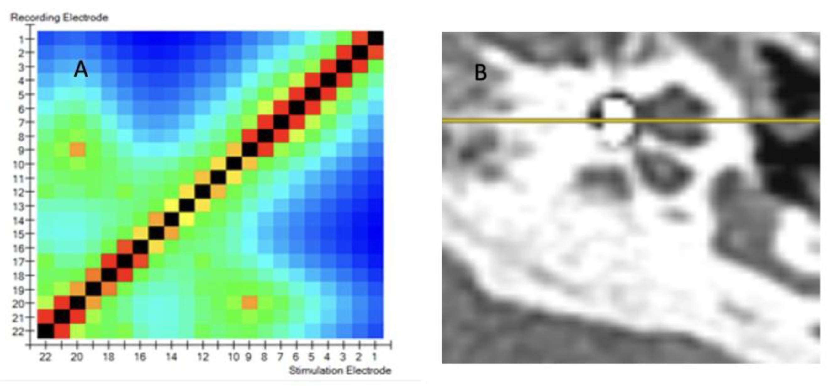
Figure 2A displays a TIM heatmap with a pattern typical for suspected tip fold over. This heatmap suggest that electrodes 9 and 20 are close to each other (two light orange points). According to the legend, impedance values are represented from dark blue to red and should spread evenly from red to blue in the HeatMap. The increase in the impedance value caused by the proximity of e.g. two electrodes (9 and 20) is visualized in this way on the HeatMap. This color pack suggests a tip-fold over the electrodes in the cochlea. TFO was confirmed by CT scan as seen in
Figure 2B. where the array is kinked and folded upon itself in the region of the pars ascendans of the cochlear lumen.
Following further work on intraoperative measurements for cochlear electrodes [
10,
11], the Smart Nav application was introduced for the detection of intraoperative TFO based on transimpedance measurement. The aforementioned studies were conducted on individuals aged 18 and above.
Based on our research and analysis of published data, previous transimpedance electrode measurements have only been conducted on adults with normal cochlear anatomy. The presented study included children with both normal ear anatomy and those with congenital ear abnormalities. To the best of our knowledge, this is the first study to demonstrate the utility of transimpedance CI measurements in pediatric populations and in cases of anatomical anomalies.
The objective of this study was to analyze intraoperative transimpedance measurements of the cochlear implant electrode with the aim of detecting electrode bending and assessing the electrode position relative to the modiolus in pediatric patients.
Previously, measurements of transimpedance mapping (TIM) have been conducted using color assessment of the transimpedance map. The objective of the analysis presented in this study was to identify statistically measurable parameters that could be used to establish norms and detect the electrode bend, which can be used both in children with normal and abnormal cochlea. The next objective was to determine the parameters that would enable the assessment of the position of the electrode in relation to the modiolus. To achieve this, the parameters for the Contour Advance and Slim Modiolar electrodes were compared, as the SM electrode is thinner and more delicate than the CA electrode, and therefore positioned closer to the modiolus [
7].
2. Materials and Methods
The study was completed in accordance with the ethical standards of the institutional research committee and principles of the World Medical Association Declaration of Helsinki Ethical Principles for Medical Research involving human subjects and its later amendments. Ethical approval for this study was obtained from the local ethics committee.
We prospectively collected the data from three cochlear implant centers enrolled in the study. The inclusion criteria were as follows: age 18 years or less; cochlear implantation with intraoperative TIM measurement.
A total of 55 pediatric patients aged 1-17 years (mean age 4.6 years) were included in the study (32 females and 23 males). A total of 62 measurements were conducted (38 in female ears and 24 in male ears). This included 50 with normal inner ear anatomy and 12 with inner ear malformations (enlarged vestibular aqueduct 3, incomplete partition II – 3, incomplete partition III – 3, cochlear hypoplasia – 1, common cavity – 1, cochlear aperture hypoplasia - 1). Children with normal ear anatomy were implanted with the Cochlear™ CA (16 children) or SM (34 children) arrays. In those with inner ear malformations the following arrays were used: Cochlear™ CA (10 children), SM (1 child), CI24RE(ST) (1 child). The surgical approach recommended by manufacturer for cochlear implantation was followed. After each implantation, a modified Stenver’s plain x-ray was obtained intraoperatively.
Establishing normative values for the TIM measurement.
Traditional impedance and Auto-NRT measurements were first acquired as per protocol for all single electrode contacts. TIM was measured by standard means of Cochlear’s CustomSound®EP Suite tool using the Cochlear Nucleus CP910 processor and Cochlear Programming Pod. For each patient TIM measurements and heatmap of impedances was obtained. The TIM data was further analyzed looking for correlations, trends and dependencies between values.
The two following principles are considered when analyzing TIM measurements: monotonicity of waveform peaks; and analysis of the diagonal of the matrix. The first principle assumes that the ideal TIM measurement has exactly one peak in each recording. Based on this principle, there is also a single black maximal peak represented on the diagonal of the matrix (see
Figure 1 C). The ideal pattern observed with a normal array in ideal position should express a monotonic decrease in values moving away from this single peak in either direction. (see
Figure 1B). The principle also assumes the diagonal of the matrix is derived from the largest impedance values. When moving away from the diagonal, the values ideally should decrease on the heatmap (see
Figure 1C). Additional peaks are therefore interpreted as occurrences of non-monotonicity.
Statistical analysis of obtained values was based on 6 parameters of TIM measurement:
1. Number of points of non-monotonicity, defined as points in the matrix, that are exempted from the principle of monotonicity. The optimal number of these points in each line should be 0. The function calculating these points allows to determine the sensitivity, i.e. whether each trend violation will be taken into account, or only a violation by a certain percentage of the median.
2. Number of peaks in the matrix. The optimal number of these points in each line should be 1. The function calculating these points allows to determine the sensitivity, i.e. whether each local extreme will be taken into account, or only one that is greater by an appropriate percentage than the bordering points.
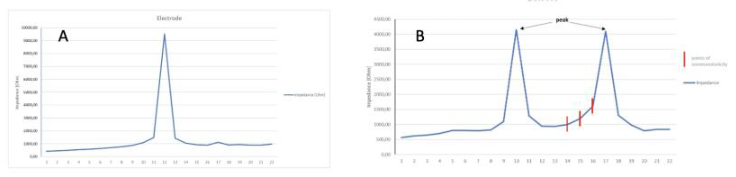
Figure 3A shows voltages measured at one electrode. Normally, there is one distinct peak for a stimulated electrode.
Figure 3B shows the abnormal cycle of inducing voltage at more than one electrode. Two peaks are visible. One primary peak is at electrode E10 and a second peak representing an occurrence of non-monotonicity is at electrode E17. When the expected values change, which should decrease and instead increase, we mark non-monotonic points. A detailed analysis of the heat map values reveals the presence of peaks that may indicate potential obstacles in the path of the impulse during impedance measurement. However, in some instances, these values may be so minimal that they are not discernible in the heat map, becoming visible only during subsequent analysis.
To assess the whole 22 lines of TIM, the following 4 parameters were assessed:
Mean number of points of non-monotonicity
Mean number of peaks in the matrix
Maximum number of points of non-monotonicity
Maximum number of peaks in the matrix
To assess the electrode position within the cochlea, the following two parameters were assessed:
1. correct construction of the diagonal
2. minimalities on the sub-diagonals
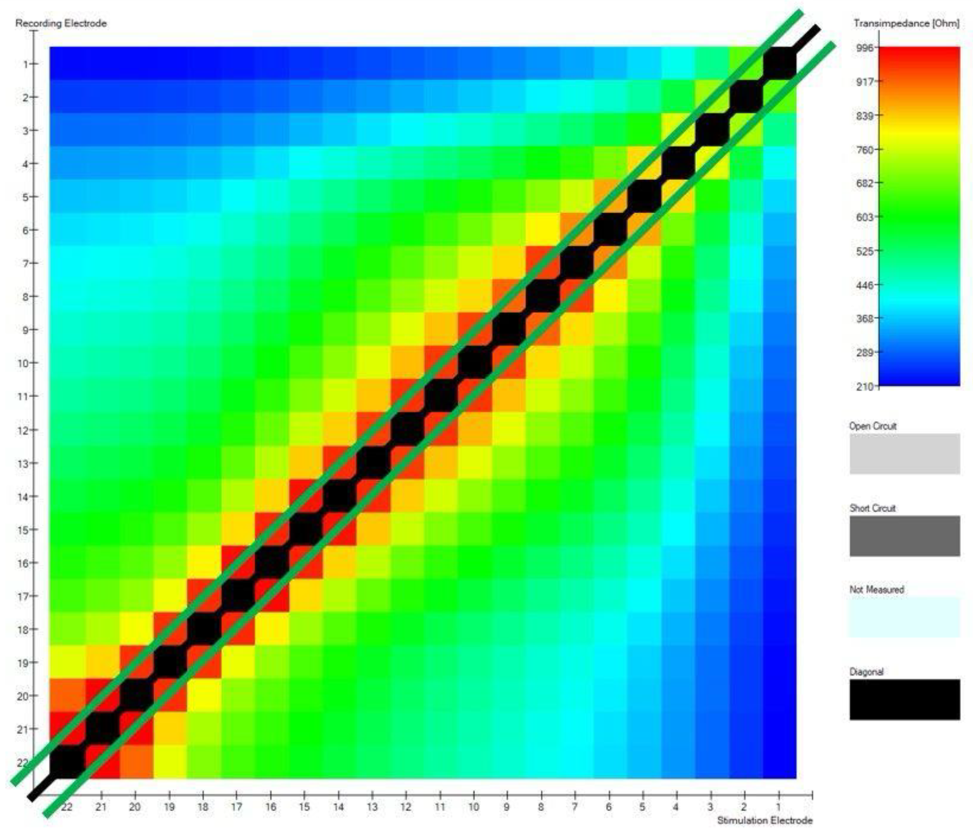
Figure 4 shows a matrix diagonal and 2 sub-diagonals that lay 1 column below and 1 above the diagonal.
These 2 parameters are based on determining 22 maximum impedance values (black line) and 42 maximum transimpedance (green lines) values after excluding the diagonal, respectively. The first measure is to determine how many of the values are on the diagonal - the best situation is when these are all 22 values. This value results from the number of electrodes in the cochlear implant. The second one describes how many of the values are on the two subdiagonals adjacent to the main diagonal - optimally, these should be all 42 values in the matrix. The optimal position of the electrodes in the modiolar CI electrode, will have 42 points on the sub-diagonals.
On the basis of transimpedance parameters, the following measurements were calculated:
mean number of points of non-monotonicity
mean number of peaks in the matrix
maximum number of points of non-monotonicity
maximum number of peaks in the matrix
correct construction of the diagonal
minimalities on the sub-diagonals
For all above mentioned parameters, a comparison was conducted between the values of the following transimpedance parameters in a group of patients with proper electrode placement in the cochlea and the values obtained in a group of patients with TFO and to compare electrodes CA and SM. .
Statistical analysis
The sensitivity of the function for calculating non-monotonicity points was assumed in the analysis at the level of 1% of the row median (i.e. only such violations of the expected trend are taken into account, which differ by at least 1% of the median compared to the previous value. The sensitivity of the function for calculating peaks was assumed at the level of 1.02, that is, only values that are greater than 1.02 times the values bordering them are taken into account as local extremes. Statistical analyses were conducted using R version 4.1.0 (R Core Team, 2021) in IDE RStudio version 1.4.1717 (RStudio Team, 2021). Visualizations were made using R version 4.1.0 and JASP (version 0.15.0.1)..
3. Results
A total of 62 measurements were conducted, in a group of 55 children. This included 50 measurements with normal inner ear anatomy and 12 with inner ear malformations. Electrode tip fold-over
TIM measurements indicated a satisfactory electrode array position in 57 out of 62 patients (92%). Five tip fold overs were observed intraoperatively (8% of all cases). One tip fold-over was diagnosed in a case with a malformed inner ear (8% of this group), and 4 instances in cases with a normally formed inner ear. (8% of this group). Interestingly, electrode tip fold-overs occurred only when the CI632 electrode was implanted.
In implants where fold-over was diagnosed, the number of points of non-monotonicity and number of peaks in the matrix were statistically significantly increased. The highest value for mean number of points of non-monotonicity in the fold-over group (n=4) was 2.091. The highest value in the group with proper electrode position (n=42) was 1.55. In 42 out of 46 measurements performed in this group mean number of points of non-monotonicity was equal to 0. Other parameters, including the construction of the diagonal and minimalities on the sub-diagonals did not reach statistical significance.
Table 1.
Results of student's t-test in all cases with detected foldover vs in a group with proper insertion.
Table 1.
Results of student's t-test in all cases with detected foldover vs in a group with proper insertion.
| Measure |
Mean value - in foldover cases |
Mean value - proper insertion cases |
T test |
df |
p |
|
3.045 |
0.064 |
-7.882 |
3.066 |
0.004 |
- 2.
mean number of peaks in the matrix |
1.727 |
1.041 |
-4.877 |
3.272 |
0.013 |
- 3.
max. points of nonmonotonicity |
5.250 |
0.109 |
-10.667 |
3.082 |
0.002 |
- 4.
maximum number of peaks in the matrix |
2.750 |
1.043 |
-3.558 |
3.024 |
0.037 |
- 5.
correctness of the diagonal construction |
0,750 |
0,935 |
0,731 |
3,131 |
0,516 |
- 6.
minimality on sub-diagonals |
32,250 |
31,783 |
-0,107 |
3,124 |
0,921 |
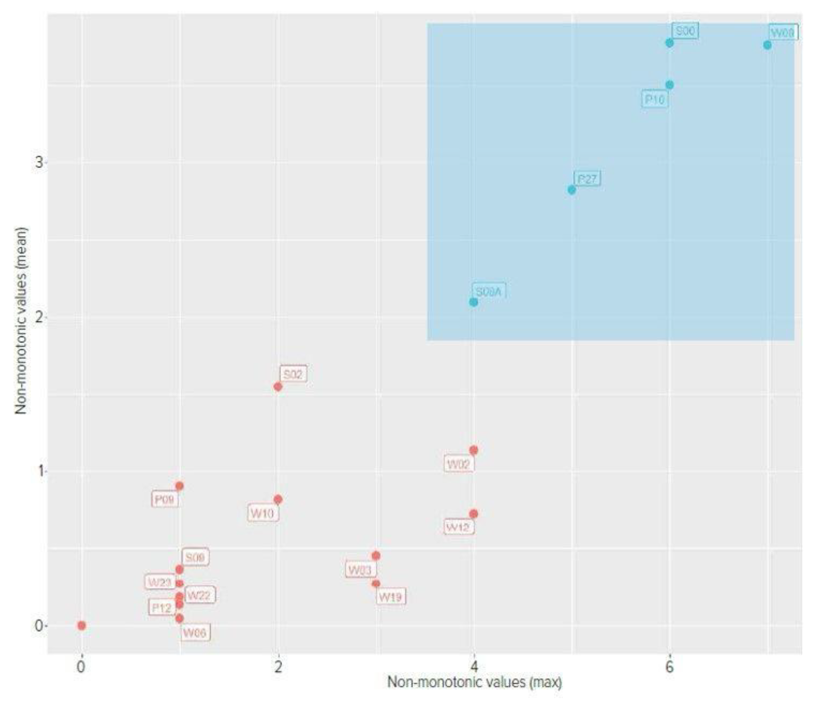
Figure 5 shows comparison of mean and maximum non-monotonic values with marking the group of patients with TFO to check whether the determined parameters properly differentiate the group of patients with normal electrode insertion and TFO. The proposed parameters resulted in the separation of the group with abnormal insertion.
Comparison of Implant Electrode Array Models
Calculations were made using the normal inner ear implantations excluding cases with electrode tip fold-over, and were based on a total of 46 measurements.
The sole parameter with statistical significance was minimalities on the sub-diagonals. This parameter can differentiate the type of electrode between Cochlear™ Nucleus® CA and SM. All other comparisons were not statistically significant.
Table 2.
Comparison of Cochlear™ CA and SM electrode arrays.
Table 2.
Comparison of Cochlear™ CA and SM electrode arrays.
| Measure |
Mean value in CA electrode |
Mean value in SM electrode |
T test |
df |
p-value |
|
0 |
0.098 |
-1.655 |
29 |
0.109 |
- 2.
mean number of peaks in the matrix |
1 |
1.063 |
-1.437 |
29 |
0.161 |
- 3.
max number of points of non-monotonicity |
0 |
0.167 |
-1.980 |
29 |
0.057 |
- 4.
maximum number of peaks in the matrix |
1 |
1.067 |
-1.439 |
29 |
0.161 |
- 5.
correctness of the diagonal construction |
1 |
0.900 |
1.795 |
29 |
0.083 |
- 6.
old>6. Minimality on sub-diagonals
|
29.750 |
32.867 |
-2.258 |
29 |
0.034 |
4. Discussion
The use of cochlear implants as a hearing prosthesis is highly efficacious; however, in order to achieve optimal outcomes, rehabilitation and training in speech perception within the implant are essential. In numerous studies, it has been demonstrated that appropriate surgical techniques and electrode placement in the cochlear scala tympani are crucial for subsequent rehabilitation and speech discrimination [
12]. It is therefore essential to develop intraoperative techniques that allow for the assessment of electrode placement accuracy within the cochlea. The use of perimodiolar electrodes presents an additional surgical challenge due to the potential risk of TFO. As previously stated, the use of radiological imaging in surgical settings presents significant challenges, with some institutions even reporting its unfeasibility. The utilization of electrophysiological measurements appears to be the optimal solution, as their implementation only marginally extends the duration of the procedure, while the requisite hardware concerns primarily a computer with the necessary software.
Electrode Tip Fold Over (TFO)
The phenomenon of the electrode implant electrode tip bending is widely discussed in the literature, but there is no consensus among authors on the appropriate course of action in such cases. Published reports indicate that the detection of TFO in CI patient groups necessitates the deactivation of certain electrodes or even no action is performed [
5]. Our analysis of the data indicates that the optimal placement of the electrode in the tympanic scale allows for the most effective rehabilitation outcomes. This is particularly relevant for pediatric patients, given that the assumption is that the implanted device should perform its function throughout the patient's lifetime. For this reason, we believe that the detection of TFO during surgery and reinsertion of the electrode is essential. The ease of detecting this complication allows for the use of electrophysiological studies. The detection of TFO based on electrophysiological measurements employs a variety of measurement techniques. As detailed in the research conducted by Verghese and colleagues, [
13] the authors proposed electrocochlearography, which demonstrated excellent sensitivity. However, specificity varied depending on the applied parameters. The success rate ranged from 41% to 68.9%, which is not an acceptable outcome when one considers the necessity of making decisions regarding electrode re-insertion and the potential trauma to the delicate cochlear structures. However, the electrocochleography method is considered effective for assessing residual hearing, both in manual electrode insertion [
14] and through the robotic surgery [
15]. Simultaneously, studies were conducted on the utilization of electrically induced potentials from the auditory nerve (eCAP). However, as demonstrated in the Grolman [
8] or Zuniga [
5] studies, eCAP-based electrophysiological measurements were challenging to detect TFO and required significant experience from the audiologist evaluating the test. Therefore, they did not meet the requirements regarding sensitivity and specificity of the method.
Proper insertion of the electrode array is crucial to outcome and this application of TIM is most widely described in the literature. The prevalence of fold-overs for all types of electrode arrays in a meta-analysis is reported to be 2% [
16]. This is best addressed with immediate repositioning; therefore, early detection of this problem is crucial. Despite low overall tip fold-over rates, the problem can be more prevalent in perimodiolar electrodes [
4,
10,
16]. Due to the precurved design and insertion technique, these seem more susceptible to fold over [
4,
10]. For CI632 Slim Modiolar electrodes used in other studies, tip fold-over rates vary between 4.3 and 10.5% for normal cochleas [
17]. Various predisposing factors for electrode fold-over have been assessed in prior studies. For electrodes implanted in our study, slight modifications in insertion techniques that can sometimes go unnoticed may have caused this complication, especially in difficult implantations. Some reported concerns include: the white handle surgical sheath being misaligned; deep insertion of the sheath in the cochlea; and electrode insertion with the tip of the array starting out of the sheath [
18]. With the growing trend towards residual hearing preservation and construction of thinner and more delicate electrodes, the risk may even be higher in future. When tip fold-over occurs, the voltages at the electrodes lying close to each other are similar. Also, the highest maximum value should still be at the stimulating electrode, but another local maximum will appear. The current version of the Smart Nav algorithm and the measurements proposed in this study allow for the detection of additional local peaks. In our study, we propose the detection of TFO in a measureable format, which may prove beneficial in subsequent investigations related to the utilization of this type of measurement, particularly in the context of robotic assisted surgery and artificial intelligence algorithms. Electrode tip fold-over can involve larger and shorter parts of the electrode. It can involve only an electrode at the tip with few contacts, or the array can fold in the middle [
11,
18]. Electrode malinsertion cannot always be felt by the surgeon and may be difficult to identify at the time of surgery [
10]. It can go undetected until later problems emerge intra- or post-operatively resulting in commonly either facial nerve stimulation or poor performance [
10]. Therefore, intraoperative diagnosis of such complications is of particular importance in pediatric patients. In our study, we demonstrated for the first time the efficacy of measurements based on TIM in children with both normal and abnormal anatomy of the internal ear. WE belive that parameters proposed in this paper may be used for all types of the electrodes, from different manufacturers, but this requires further investigation.
Perimodiolar electrode position
The current version of the Smart Nav application has not impeded the advancement of research into the potential of TIM for assessing the positioning of electrodes close to the modiolus. This is due in part to the fact that it allows for the assessment of potential electrode bending, but does not provide the capability to evaluate individual parameters.
Salkim et al. [
19] conducted experimental studies on cochlear models, measuring impedance with simultaneous electrode position assessment. They demonstrated the intraoperative utility of these measurements in determining the position of the electrode relative to the scala tympani border. This type of electrode placement is of significant clinical relevance for subsequent rehabilitation, as demonstrated by Aschendorf [
2].
Gottfried and colleagues in their study [
20] used the impedance measurements performed during electrode insertion, in conjunction with the eCAP readings, pertained to the straightforward MedEl electrodes. Consequently, direct comparisons are challenging. Nevertheless, this study points to the potential for further studies in impedance measurement. Furthermore, given the optimal perimodiolar arrangement of the electrode, it would be prudent to consider the results published by Aschendorff and colleagues [
2]. The aforementioned researchers demonstrated that in instances of excessive insertion depth called “over insertion” of the electrode SM, there is a tendency for the electrode to deviate from the helical pitch at the bend in the shaft. With this problem in mind, Lee and colleagues [
21], in their experimental study, employed the pull-back technique, which yielded more favorable results in eCAP parameters [
21]. This maneuver was implemented with the objective of preventing over-insertion. Radiological studies are not as precise as electrophysiological measurements in evaluating the electrode placement within the cochlea [
11,
21]. Recently, such measurements have been conducted, based on impedance measurements in Rijoas studies [
22,
23]. These measurements were taken during robotic insertion and demonstrated the utility of impedance measurements in the vicinity of the electrode in relation to the cochlear modiolus. The proposed parameters minimality of the subdiagonal parameters permit a statistically measurable measurement of the modiolar proximity covering of the entire electrode. The results of the measurements indicate the possibility of distinguishing between the SM and CA electrodes, in consideration of their position relative to the cochlear modiolus. However, this requires confirmation in larger patient groups but seems to promising parameter to use in further studies.
The introduction of the Smart Nav application undoubtedly facilitated daily work on the surgical theater and enabled intraoperative detection of TFO. However, the requirements imposed on implantable hearing devices are considerable. Such devices are already implanted in children below the age of one, with the expectation that they will be used throughout their lifetime. They are significantly more sophisticated and encompass a wider range of parameters. Electrophysiological measurements of cochlear implants retain considerable potential for application in both conventional insertions and the rapidly evolving field of robotic surgery [
15]. Nevertheless, further research is required to determine which parameters will be applicable in clinical practice and to identify suitable, reproducible parameters for this purpose.
It would be optimal to create a tool based on different parameters. Such a tool would enable surgeons to determine the optimal position and depth of insertion for cochlear nerve stimulation intraoperatively, while preserving residual hearing. The application of an algorithm that employs both eCAP and transimpedance parameters would facilitate the optimal positioning of the electrode during surgical procedures, both those performed manually by the surgeon and those conducted using robotic surgery. Such electrode positioning will facilitate superior rehabilitation outcomes while simultaneously reducing future energy consumption by the fully implantable CI. As is widely acknowledged, the objective is to develop fully insertable implants. However, research is still being conducted to identify methods of obtaining the requisite electrical energy for the optimal functioning of the implanted hearing system. In order to achieve the aforementioned objectives, it is necessary to have tools that allow for a statistically measurable evaluation of results. One such tool is the proposed parameters, which are presented in this study..
5. Conclusions
TIM measurement is a quick and reliable method for detecting electrode array tip fold-over intraoperatively. The measurement can be conducted with no additional radiation exposure, which is especially important in children. It can be used as a cross-check method or even has the potential to fully replace intraoperative x-ray based imaging. Our results confirm that TIM measurement with our methodology, diagnoses TFO in all our cases, can be used as a new tool for assessing the position of the electrode in relation to the modiolus.
To our knowledge, this study is the first to report experience with TIM in children with normal cochlear anatomy and inner ear malformations. We believe that in inner ear malformations TIM measurement is a quick, intraoperative measurement, that may confirm good electrode position within the cochlea in difficult cases.
Our study complements the knowledge about the use of research based on transimpedance matrix measurement and opens completely new possibilities for using this tool on large databases, e.g. in the context of using AI-based tools and robotic surgery.
Author Contributions
“Conceptualization, K.R., M.T., J.M.; methodology, K.R., M.T. and J.M.; software, M.T.; validation, K.R., M.T.; formal analysis K.R. and M.T..; investigation, K.R., M.T., J.M..; resources, X.X.; data curation, MT, KH.; P.M.D.; writing—original draft preparation, K.R.; writing—review and editing, K.R., A.J.F. and J.M.; visualization, K.R. and M.T..; supervision, K.R. and J.M.”
Funding
This research did not receive any specific grant from funding agencies in the public, commercial, or not-for-profit sectors.
Institutional Review Board Statement
Ethical approval for this study was obtained from the Ethics Committee of Pomeranian Medical University in Szczecin. Trial registration number KB/2019/129. The study was completed in accordance with the ethical standards of the institutional research committee and principles of the World Medical Association Declaration of Helsinki Ethical Principles for Medical Research involving human subjects and its later amendments.
Data Availability Statement
Data connected with this study are available on request from corresponding author.
Conflicts of Interest
Marcin Talar is an employee at Medicus Sp. z o.o. company. The other authors do not have relationships to disclose that may pose conflicts of interest.
References
- Perenyi, A.; Toth, F.; Dimak, B.; Nagy, R.; Schoerg, P.; Jori, J.; Kiss, J.G.; Sprinzl, G.; Csanady, M.; Rovo, L. Electrophysiological measurements with electrode types of different perimodiolar properties and the same cochlear implant electronics - a retrospective comparison study. J Otolaryngol Head Neck Surg. 2019, 48, 46. [Google Scholar] [CrossRef] [PubMed] [PubMed Central]
- Aschendorff, A.; Briggs, R.; Brademann, G.; Helbig, S.; Hornung, J.; Lenarz, T.; Marx, M.; Ramos, A.; Stöver, T.; Escudé, B.; James, C.J. Clinical investigation of the Nucleus Slim Modiolar Electrode. Audiol Neurootol. 2017, 22, 169–179. [Google Scholar] [CrossRef] [PubMed]
- Haber, K.; Neagu, A.; Konopka, W.; Amernik, K.; Gheorghe, D.C.; Drela, M.; Wrukowska-Niemczewska, I.; Mierzwiński, J. The influence of Slim Modiolar electrode on residual hearing in pediatric patients. Eur Arch Otorhinolaryngol. 2021, 278, 2723–2732. [Google Scholar] [CrossRef] [PubMed]
- Gabrielpillai, J.; Burck, I.; Baumann, U.; Stöver, T.; Helbig, S. Incidence for Tip Foldover During Cochlear Implantation. Otol Neurotol. 2018, 39, 1115–1121. [Google Scholar] [CrossRef]
- Zuniga, M.G.; Rivas, A.; Hedley-Williams, A.; Gifford, R.H.; Dwyer, R.; Dawant, B.M.; Sunderhaus, L.W.; Hovis, K.L.; Wanna, G.B.; Noble, J.H.; Labadie, R.F. Tip Fold-over in Cochlear Implantation: Case Series. Otol Neurotol. 2017, 38, 199–206. [Google Scholar] [CrossRef]
- Fishman, A.J.; Roland JTJr Alexiades, G.; Mierzwinski, J.; Cohen, N.L. Fluoroscopically assisted cochlear implantation. Otol Neurotol. 2003, 24, 882–6. [Google Scholar] [CrossRef]
- Perényi, Á.; Nagy, R.; Dimák, B.; Csanády, M.; Jóri, J.; Kiss, J.G.; Rovó, L. Cochlearis implantátumok különböző, előre görbített elektródasorainak elhelyezkedése a cochlea tengelyéhez viszonyítva. Radiológiai vizsgálat a perimodiolaritás mértékének megállapítására [The distance from the modiolus of perimodiolar electrode arrays of cochlear implants. A radiological study to evaluate the difference in perimodiolar properties]. Orv Hetil. 2019, 160, 1216–1222 Hungarian. [Google Scholar] [CrossRef] [PubMed]
- Grolman, W.; Maat, A.; Verdam, F.; Simis, Y.; Carelsen, B.; Freling, N.; Tange, R.A. Spread of excitation measurements for the detection of electrode array foldovers: a prospective study comparing 3-dimensional rotational x-ray and intraoperative spread of excitation measurements. Otol Neurotol. 2009, 30, 27–33. [Google Scholar] [CrossRef]
- Vanpoucke, F.J.; Boermans, P.P.; Frijns, J.H. Assessing the placement of a cochlear electrode array by multidimensional scaling. IEEE Trans Biomed Eng. 2012, 59, 307–10. [Google Scholar] [CrossRef]
- Hoppe, U.; Brademann, G.; Stöver, T.; Ramos de Miguel, A.; Cowan, R.; Manrique, M.; Falcón-González, J.C.; Hey, M.; Baumann, U.; Huarte, A.; Liebscher, T.; Bennett, C.; English, R.; Neben, N.; Ramos Macías, A. Evaluation of a Transimpedance Matrix Algorithm to Detect Anomalous Cochlear Implant Electrode Position. Audiol Neurootol. 2022, 27, 347–355. [Google Scholar] [CrossRef]
- Leblans, M.; Zarowski, A.; Molisz, A.; van Dinther, J.; Dedeyne, J.; Lerut, B.; Kuhweide, R.; Offeciers, E. Cochlear implant electrode array tip-foldover detection by electrode voltage telemetry. Cochlear Implants Int. 2023, 24, 95–106. [Google Scholar] [CrossRef] [PubMed]
- Holden, L.K.; Finley, C.C.; Firszt, J.B.; Holden, T.A.; Brenner, C.; Potts, L.G.; Gotter, B.D.; Vanderhoof, S.S.; Mispagel, K.; Heydebrand, G.; Skinner, M.W. Factors affecting open-set word recognition in adults with cochlear implants. Ear Hear. 2013, 34, 342–60. [Google Scholar] [CrossRef] [PubMed]
- Varghese, J.J.; Walia, A.; Lefler, S.M.; Ortmann, A.J.; Shew, M.A.; Durakovic, N.; Wick, C.C.; Herzog, J.A.; Buchman, C.A. Identifying Slim Modiolar Electrode Tip Fold-Over With Intracochlear Electrocochleography. Otolaryngol Head Neck Surg. 2024, 170, 1124–1132. [Google Scholar] [CrossRef] [PubMed]
- Harris, M.S.; Riggs, W.J.; Giardina, C.K.; O'Connell, B.P.; Holder, J.T.; Dwyer, R.T.; Koka, K.; Labadie, R.F.; Fitzpatrick, D.C.; Adunka, O.F. Patterns Seen During Electrode Insertion Using Intracochlear Electrocochleography Obtained Directly Through a Cochlear Implant. Otol Neurotol. 2017, 38, 1415–1420. [Google Scholar] [CrossRef] [PubMed]
- Gawęcki, W.; Balcerowiak, A.; Podlawska, P.; Borowska, P.; Gibasiewicz, R.; Szyfter, W.; Wierzbicka, M. Robot-Assisted Electrode Insertion in Cochlear Implantation Controlled by Intraoperative Electrocochleography-A Pilot Study. J Clin Med. 2022, 11, 7045. [Google Scholar] [CrossRef] [PubMed] [PubMed Central]
- Jwair, S.; Prins, A.; Wegner, I.; Stokroos, R.J.; Versnel, H.; Thomeer, H.G.X.M. Scalar Translocation Comparison Between Lateral Wall and Perimodiolar Cochlear Implant Arrays - A Meta-Analysis. Laryngoscope. 2021, 131, 1358–1368. [Google Scholar] [CrossRef]
- Klabbers, T.M.; Huinck, W.J.; Heutink, F.; Verbist, B.M.; Mylanus, E.A.M. Transimpedance Matrix (TIM) Measurement for the Detection of Intraoperative Electrode Tip Foldover Using the Slim Modiolar Electrode: A Proof of Concept Study. Otol Neurotol. 2021, 42, e124–e129. [Google Scholar] [CrossRef]
- Ramos-Macias, A.; RDe Miguel, A.; Falcon-González, J.C. Mechanisms of electrode fold-over in cochlear implant surgery when using a flexible and slim perimodiolar electrode array. Acta Otolaryngol. 2017, 137, 1129–1135. [Google Scholar] [CrossRef]
- Salkim, E.; Zamani, M.; Jiang, D.; Saeed, S.R.; Demosthenous, A. Insertion Guidance Based on Impedance Measurements of a Cochlear Electrode Array. Front Comput Neurosci. 2022, 16, 862126. [Google Scholar] [CrossRef]
- Gottfried, T.M.; Galeazzi, P.; Föger, A.; Dejaco, D.; Tröger, A.; Fischer, N.; Innerhofer, V.; Di Trapani, F.; Weiss, N.; Seebacher, J.; Dierker, A.; Schmutzhard, J. Evaluation of an impedance-based method to monitor the insertion of the electrode array during cochlear implantation. Eur Arch Otorhinolaryngol. 2024, 281, 4121–4131. [Google Scholar] [CrossRef]
- Lee, S.Y.; Kim, Y.S.; Jo, H.D.; et al. Effects of in vivo repositioning of slim modiolar electrodes on electrical thresholds and speech perception. Sci Rep 2021, 11, 15135. [Google Scholar] [CrossRef]
- Riojas, K.E.; Bruns, T.L.; Granna, J.; Webster, R.J., 3rd; Labadie, R.F. Robotic pullback technique of a precurved cochlear-implant electrode array using real-time impedance sensing feedback. Int J Comput Assist Radiol Surg. 2023, 18, 413–421. [Google Scholar] [CrossRef]
- Riojas, K.E.; Bruns, T.L.; Granna, J.; Smetak, M.R.; Labadie, R.F.; Webster, R.J., 3rd. Towards inferring positioning of straight cochlear-implant electrode arrays during insertion using real-time impedance sensing. Int J Med Robot. 2024, 20, e2609. [Google Scholar] [CrossRef]
- Pile, J.; Sweeney, A.D.; Kumar, S.; Simaan, N.; Wanna, G.B. Detection of modiolar proximity through bipolar impedance measurements. Laryngoscope. 2017, 127, 1413–1419. [Google Scholar] [CrossRef] [PubMed]
|
Disclaimer/Publisher’s Note: The statements, opinions and data contained in all publications are solely those of the individual author(s) and contributor(s) and not of MDPI and/or the editor(s). MDPI and/or the editor(s) disclaim responsibility for any injury to people or property resulting from any ideas, methods, instructions or products referred to in the content. |
© 2024 by the authors. Licensee MDPI, Basel, Switzerland. This article is an open access article distributed under the terms and conditions of the Creative Commons Attribution (CC BY) license (http://creativecommons.org/licenses/by/4.0/).