
Submitted:
11 December 2024
Posted:
12 December 2024
You are already at the latest version
Abstract
The most commonly used membranes are of the "thin film composite" (TFC) type, consisting of three layers of polymers. Membrane modification has been explored through two main approaches: optimizing the polymer before fabrication or modifying the surface after fabrication. This study focuses on membrane modification by depositing ultrathin films of zinc oxide (ZnO) using the sputtering process. The impact on permeability and monovalent ion rejection is examined. The results show that an increase in ZnO deposition time leads to a reduction in permeate flux density, albeit with an improvement in monovalent ion rejection. The Spielger-Kedem model is demonstrated to effectively predict the behavior of these membranes. Collectively, the findings suggest that membrane modification with ZnO through sputtering can offer significant advantages in water purification applications, albeit with considerations regarding reduced permeate flux density.
Keywords:
Membrane Fouling
; Spielger – Kedem Model
; Sputtering
; Water purification
; Modifying membranes
1. Introduction
Currently, more than one-third of the global population resides in areas categorized as "water-stressed regions," resulting from the imbalance between the demand for freshwater and its supply [1]. The utilization of water purification technologies based on membranes is emerging as a promising solution to address this issue. Remarkable technological advancements and cost reductions have facilitated the proliferation of pressure-driven membrane processes, such as reverse osmosis (RO) and nanofiltration (NF) [2].
However, one of the fundamental challenges associated with these separation methods is the fouling phenomenon. This issue leads to a continuous reduction in membrane permeability, resulting in increased retention of low molecular weight solutes and, ultimately, the blockage of flow channels. This degradation directly impacts operational costs by reducing performance and necessitating more frequent cleaning cycles, thereby shortening the membrane's lifespan [3,4,5]. It is important to note that the membrane unit's cost constitutes approximately 20-25% of the total system cost, and it is estimated that around 10% of the membranes need to be replaced annually to maintain optimal operation [6].
The most commonly employed membranes are of the "thin film composite" (TFC) type, which consists of three different polymer layers. These layers include a thick layer of polyester, another of polysulfone, and finally, a thin and dense layer of polyamide, known as the "active layer," responsible for the separation [7].
In the quest to enhance resistance to fouling, materials researchers have explored two primary approaches. The first involves modifying a polymer to a greater extent and then manufacturing the membrane using that optimized composition. The second method, seemingly simpler and more cost-effective, entails preparing the membrane from a standard polymer and subsequently altering its surface [8]. While the first approach demands specific optimization for each particular application, the second offers the possibility of creating a wide variety of new membranes based on the original matrix [9].
As a result of this research, various modification strategies for conventional membranes have been examined. Among these techniques, particular attention has been devoted to the incorporation of metals and metal oxides, with the aim of enhancing membrane permeability, selectivity, mechanical strength, and hydrophilicity [9]. Metals are typically deposited in the form of thin layers on various substrates to increase flow through the membranes and ensure adequate mechanical strength, thermal stability, and durability [10].
On the other hand, zinc oxide (ZnO) is generally considered a non-toxic material. Furthermore, since the 1960s, it has been discovered that ZnO possesses piezoelectric semiconductor properties, meaning it can convert mechanical energy into an electrical signal. Zinc oxide compounds and their derivatives have proven effective in controlling fungi in various applications, acting as fungistats by inhibiting the growth of fungi such as mold on various surfaces [11].
The Sputtering method is based on the impact of energized particles on the surface, causing the surface atoms to be scattered backward upon collision with these particles. This results in an ultra-thin film of the target material being deposited on the surface [12]. The process involves placing the substrate and the target in a high vacuum chamber in contact with a plasma, allowing the material to be transported from the target to the substrate, where the film is formed [12]. The film's thickness, the phase of the metallic material, and the material's distribution can be controlled by manipulating the generated plasma. This is achieved through adjustments to the operating pressure, the ratio of reactive gas to noble gas, current power or intensity, the distance between the target and the substrate, and deposition times.
The purpose of this study is to carry out the deposition of ultra-thin zinc oxide films through the Sputtering process, using a radiofrequency (RF) magnetron. These films will be deposited onto a commercial nanofiltration membrane used in the desalination of seawater. The primary objective is to assess the performance of these membranes in terms of permeability and ion rejection capacity. The research will be carried out in two distinct phases. In the first stage, the focus will be on evaluating the optimal deposition conditions for the films. Subsequently, in a second phase, the assessment of the applicability and feasibility of these membranes in the context of desalination will be addressed.
2. Materials and Methods
The NF90 membrane manufactured by Dupont/FilmTec was used. The NF90 is a nanofiltration membrane consisting of a thin-film composite (TFC) over a microporous polysulfone intermediate layer and a polyester support layer. For detailed information on the properties of this membrane, you can refer to previous research conducted by our research team.
The ZnO coating on the polyamide membrane (NF90) was carried out in a 10-inch square chamber using the ion sputtering process. A ZnO target with a purity of 99.99%, a radiofrequency source (Advanced Energy's Cesar RF power Generator), and a distance of 10 cm between the membrane and the magnetron were employed. Before commencing the deposition process, the vacuum chamber was evacuated to achieve a minimum pressure of 4x10⁻⁵ Torr. During the coating process, high-purity Argon gas with a purity of 99.999% was used at a flow rate of 10 sccm, resulting in a deposition pressure of 5.3x10⁻³ Torr. The power used in the process was 100 W. Various deposition times were employed for the coating, including intervals of 30, 60, and 120 seconds.
Scanning electron microscopy (SEM) was used with the JEOL JSM-6390LV equipment to perform the analysis of surface morphology modifications of the membrane. In this process, the membrane was coated with a gold layer of approximately 400 Åm before taking measurements. X-ray diffraction (XRD) technique was employed using the PaNalytical X'Pert3 Powder equipment to confirm the presence of crystalline phases and to verify the deposition of ZnO, Cu, and Cu2O layers. Scanning was performed in a 2θ range from 5° to 90°. This technique is particularly advantageous as it is non-destructive and offers precise structural information regarding the chemical composition of the membranes, enabling the identification of material phases present.
The contact angle values were obtained using the Drop Shape Analyzer equipment, DSA25S model by KRÜSS. The Advance software was used to assess chemical and morphological variations on the membrane's surface. In this process, a volume of 10 μL of deionized water was applied, and contact angles were measured using the "sessile drop" technique. Subsequently, the Wenzel Equation was applied to eliminate any contributions arising from roughness in this measurement, enabling a more accurate evaluation of the contact angles.
μ=cos(φ)=rcos(θ)
With cos(φ) as the intrinsic wettability and r as the roughness factor or Wenzel factor, which corresponds to the ratio between the actual surface area and the geometric surface area and can be obtained through AFM analysis.
Roughness measurements were conducted on the nanofiltration membranes, both in their original state and in the modified versions, using an Atomic Force Microscope (AFM) in AC mode with an OmegaScope 1000 (AIST-NT Inc., USA). These measurements were performed in non-contact mode of AFM.
All filtration tests were conducted at the laboratory level using a Sterlitech HP4750 cell. This filtration system operated in dead-end mode, with an active membrane area of 15.9 cm² and was subjected to a range of pressures ranging from 2 to 40 bar, using pressurized nitrogen. The experiments were carried out at a constant temperature of 24 ±1°C. Prior to each test, the membranes underwent a washing process with distilled water to remove any residual substances in the system. Subsequently, the membranes were compacted at a pressure of 10 bars for a period of one hour.
The permeate flux density (JW) is calculated according to equation (2).
Where ΔV/Δt is the permeated volume over time and Am is the effective filtration area. The hydraulic permeability constant (kw) was determined using the following expression.
Where ∆P is the operational pressure difference between feed and permeate. The observed rejection efficiency of species was assessed by measuring the conductivity of the feed and the permeate using the following expression:
In this equation, Cfs represents the conductivity or concentration of heavy metal ions in the feed, while Cps refers to the conductivity of ion concentration in the permeate. Since nanofiltration membranes have been adequately represented by the Spiegler-Kedem (SK) model, which treats the membrane's performance as a black box and considers an irreversible thermodynamic process, it is proposed to employ this model to examine its approach to the phenomenon occurring in these membranes.
This model has been widely employed to describe the membrane based on two key parameters: the reflection coefficient (σ) and solute permeability (Ps). For a two-component system composed of a solute and water, where Jw and Js represent the water and solute fluxes, respectively, it can be expressed as follows [14]:
In this equation, Δπ represents the difference in osmotic pressure of the solution, ΔCs is defined as Cms - Cps, where Cms is the solute concentration at the membrane surface. According to equation (6), the solute flow consists of the sum of diffusive and convective terms. The difference in osmotic pressure (Δπ) can be calculated using the Vant-Hoff equation:
Where Rg is the ideal gas constant, T is the temperature, and m is the molar mass of the solute. According to the Spielger-Kedem model, the permeability coefficient (Ps) and the reflection coefficient (σ) can be obtained by solving the following equations [14]:
Where F is a dimensionless parameter, and RR is the actual solute rejection. The actual rejection can also be defined as follows:
The model establishes a relationship between solute concentration at the membrane and solute concentration in the permeate. However, to account for concentration polarization, it is necessary to combine this model with film theory through a correlation that allows for the determination of the mass transfer coefficient (ks). This transfer coefficient is subject to variations due to factors such as feed velocity, temperature, and geometry. The relationship between solute concentration at the surface and in the permeate can be expressed as follows [15]:
Where ks is defined as:
In this equation, Dsw represents the solute diffusion coefficient, and δ denotes the thickness of the concentration polarization layer. Furthermore, the mass transfer coefficient is related as follows:
Where Re is the Reynolds number and Schmidt number is defined as:
Then, both models were combined, expressing the rejection as [17]:
3. Results
3.1. Physical and chemical evaluations of ZnO-modified membrane
The morphology of the modified membranes is presented in Figure 1. Figure 1.a corresponds to the unmodified membrane, while Figures 1.b, 1.c, and 1.d show the membranes with ZnO deposits of 30, 60, and 120 seconds, respectively. Upon examining the images, it can be observed that with short exposure times, a thin layer is deposited, and no significant discernible differences are observed under the scanning electron microscope (SEM).
A study of surface modification was also conducted using X-ray Diffraction Spectroscopy (XRD), as depicted in Figure 2. The results reveal the crystalline structure of the unmodified membrane, characterized by peaks located at 2θ = 17.8, 22.9, and 26.1°, corresponding to the (O C) phases for the first two peaks and the (O C N) phase for the last one [18].
In the case of the modified membranes (see Figure 2), the appearance of four peaks at 31.7, 34.3, 36.4, and 63° is observed, corresponding to the (100), (002), (101), and (103) peaks, respectively. These results align with the pattern PDF#36-1451 of the hexagonal Wurzite structure of ZnO. A preferential orientation is observed in the (002) plane, which exhibits lower surface tension and, consequently, greater growth in this direction, a characteristic feature in ZnO films [19,20]. Due to the high deposition rate and associated energy in this process, the (100) and (101) planes are also favored, resulting in parallel growth with a polycrystalline structure. For deposition times exceeding 60 seconds, the appearance of ZnO on the (103) plane is detected.
Figure 3 displays the contact angles of the original membrane and the modified membranes. Firstly, the results obtained for the original membrane align with what has been reported in previous research [21,22]. On the other hand, the images illustrate that the coating layer increases the hydrophobicity of the membrane in comparison to the original membrane material.
Furthermore, it is observed that the contact angle increases proportionally with the exposure time in the Sputtering process, reaching a value of 140.35 ± 3.88°. Since the exposure time is directly related to the amount of ZnO deposited on the surface, it is evident that the contact angle increases with the quantity of target material deposited on the substrate, which aligns with previous findings [23].
The AFM images of the membranes modified through the Sputtering process are presented in Figure 4, while Table 1 shows the values of root mean square roughness (RMS), Ra, and the Wenzel factor for an image size of 10x10 μm. The results indicate that the thickness of the coating layer increases to 230.7 nm after 30 seconds of exposure and to 249.1 nm after 60 seconds of deposition. However, a reduction in roughness is observed, down to 174 nm for a deposition time of 120 seconds. This phenomenon can be explained by the fact that during the initial exposure periods, ZnO is primarily deposited on the (002) plane. As the deposition time increases, ZnO begins to deposit on other planes, such as (100), (101), and (103). If we consider that deposition on the (002) plane could be the main contributor to substrate roughness, the incorporation of ZnO on the other planes could lead to a reduction in the observed increase in roughness.
3.2. Non-Permeate Flux Performance of Modified Membranes
Figure 5 illustrates the impact of modification through the incorporation of ZnO into the NF90 membrane on water flux density. It is observed that the modified membranes exhibit lower permeate flux density values compared to the commercial membrane. Reducing the exposure time during the RF Sputtering modification process results in higher permeate flux density values.
As a result, an excess of exposure time leads to the accumulation of a thicker ZnO layer, which in turn decreases the water flow through the membrane pores. This phenomenon follows similar patterns to those found in previous research related to reverse osmosis membranes [24]. It is important to note that the different exposure times of the membrane generate reductions in permeate flux density, which are 47.0%, 47.1%, and 49.6% in comparison to the original flux density of the NF90 membrane for exposure times of 30, 60, and 120 seconds, respectively.
The permeability efficiency of modified membranes depends significantly on several key parameters, such as the deposited ZnO concentration, hydrophobicity, roughness, and pore size. An excess of deposited ZnO can block the pores and, consequently, reduce the water flow through the membrane. In the case of hydrophobicity, an increase in exposure leads to an increase in surface hydrophobicity, which, in turn, reduces water interaction with the surface and, as a result, decreases the permeate flux density.
In contrast, an increase in surface roughness could theoretically enhance permeate flow by providing a greater available area for transfer. However, it's important to note that this assumption cannot be confirmed with the current results
Regarding ion rejection, there is an observed trend of increasing rejection as the ZnO deposition time is extended, as shown in Figure 6. This trend is particularly evident at operating pressures of 10 and 20 bars. However, at higher pressures, there does not appear to be a significant increase in ion rejection when extending the ZnO deposition time from 60 to 120 seconds on the membrane surface.
The application of the Spielger-Kedem model to the pristine membrane and the modified membranes is graphically represented in Figure 7. The calculated parameters for the model are detailed in Table 2. It is evident that the model is suitable for predicting solute transport through these membranes. The high correlation between experimental data and model predictions supports the notion that membrane transport can be explained by the diffusion and convection of uncharged molecules.
4. Conclusions
This study analyzed the influence of surface modification of membranes through the deposition of thin layers of ZnO with different times to evaluate the seawater desalination performance. The most relevant results are presented below:
It is entirely feasible to use the surface modification method known as Sputtering to deposit metals and metal oxides on a nanofiltration membrane made of polyamide without causing any damage to its surface.
As the deposition time of the thin ZnO layers increases, orientations in the crystal planes (100), (101), and (103) are induced, in addition to the preferred plane (002) observed at shorter deposition times.
The ZnO deposition process on the membrane has the potential to increase the rejection of monovalent ions by up to 10%. However, this increase is accompanied by a significant decrease in the permeate flux density, which can be reduced by up to 40%.
It is important to highlight that the Spielger-Kedem model proves effective in predicting experimental results accurately for all modified membranes. Under this approach, membrane transport can be adequately explained as the result of diffusion and convection of uncharged molecules.
Author Contributions
Conceptualization, C.V., L-P. and J.R.; research, C.V., L.P., D,P., E.P.T., F.S.P., and A.F.C.; data curation, M.M., J.R. and C.V.; writing—original draft preparation, C.V., L.P. and R.B.; writing—review and editing, C.V., L.P., M.M. and R.B.; visualization, C.V and L.P.; supervision, R.B., M.M., E.P.T. and F.S.P.; project management, M.M.; acquisition financing, L.P., M.M., E.P.T. and D,P. All authors have read and agreed to the published version of the manuscript.
Funding
This work was funded by the Chilean National Agency for Research and Development (ANID) with the project FONDEF ID21I10017 and FONDECYT Postdoctorade 2022 – 3220371. FONDEQUIP Project No EQM150139; Project VRID No 2021-000-005P; project Grant No 1190469.
Acknowledgments
M.M. I would like to thank Valentina Lamilla for her enormous support. And
Conflicts of Interest
The authors declare no conflicts of interest.
Data Availability
The data used in this research are available upon request.
References
- Goh, P.S.; Lau, W.J.; Othman, M.H.D.; Ismail, A.F. Membrane fouling in desalination and its mitigation strategies. Desalination 2018, 425, 130–155. [Google Scholar] [CrossRef]
- Wadekar, S.S.; Vidic, R.D. Influence of Active Layer on Separation Potentials of Nanofiltration Membranes for Inorganic Ions. Environmental science & technology 2017, 51, 5658–5665. [Google Scholar] [CrossRef]
- Guo, W.; Ngo, H.H.; Li, J. A mini-review on membrane fouling. Bioresource technology 2012, 122, 27–34. [Google Scholar] [CrossRef] [PubMed]
- Al-Rashdi, B.A.M.; Johnson, D.J.; Hilal, N. Removal of heavy metal ions by nanofiltration. Desalination 2013, 315, 2–17. [Google Scholar] [CrossRef]
- Shirazi, S.; Lin, C.-J.; Chen, D. Inorganic fouling of pressure-driven membrane processes A critical review. Desalination 2010, 250, 236–248. [Google Scholar] [CrossRef]
- Zhao, X.; Zhang, R.; Liu, Y.; He, M.; Su, Y.; Gao, C.; Jiang, Z. Antifouling membrane surface construction: Chemistry plays a critical role. Journal of Membrane Science 2018, 551, 145–171. [Google Scholar] [CrossRef]
- Zou, H.; Jin, Y.; Yang, J.; Dai, H.; Yu, X.; Xu, J. Synthesis and characterization of thin film composite reverse osmosis membranes via novel interfacial polymerization approach. Separation and Purification Technology 2010, 72, 256–262. [Google Scholar] [CrossRef]
- Rana, D.; Matsuura, T. Surface modifications for antifouling membranes. Chem Rev 2010, 110, 2448–2471. [Google Scholar] [CrossRef] [PubMed]
- Hilal, N.; Khayet, M.; Wright, C.J.; Modification, M.; Applications; Taylor & Francis, 2012.
- P. Luis, Chapter 1 - Introduction, in: P. Luis (Ed.) Fundamental Modelling of Membrane Systems, Elsevier, 2018, pp. 1-23.
- Moezzi, A.; McDonagh, A.M.; Cortie, M.B.; Zinc oxide particles: Synthesis; properties; applications; Journal, C.E.2012) 1-22.
- Adachi, H.; Hata, T.; Wasa, K. 5 - Basic Process of Sputtering Deposition, in: Handbook of Sputtering Technology (Second Edition), William Andrew Publishing, Oxford, 2012, pp. 295–359.
- Wenzel, R.N. Resistance of Solid Surfaces to Wetting by Water. Industrial & Engineering Chemistry 1936, 28, 988–994. [Google Scholar] [CrossRef]
- Nair, R.R.; Protasova, E.; Strand, S.; Bilstad, T. Implementation of Spiegler–Kedem and Steric Hindrance Pore Models for Analyzing Nanofiltration Membrane Performance for Smart Water Production Membranes 2018, 8, 78. [CrossRef]
- Andalaft, J.; Schwarz, A.; Pino, L.; Fuentes, P.; Bórquez, R.; Aybar, M. Assessment and Modeling of Nanofiltration of Acid Mine Drainage. Industrial & Engineering Chemistry Research 2018, 57, 14727–14739. [Google Scholar] [CrossRef]
- Chong, T.H.; Fane, A.G. Nanofiltration Module Design and Operation, in: Nanofiltration, 2021, pp. 95–135.
- Ahmed, F.N. Modified Spiegler-Kedem Model to Predict the Rejection and Flux of Nanofiltration Processes at High NaCl Concentrations, in, 2013.
- Agboola, O.; Mokrani, T.; Sadiku, R. Porous and fractal analysis on the permeability of nanofiltration membranes for the removal of metal ions. Journal of Materials Science 2015, 51, 2499–2511. [Google Scholar] [CrossRef]
- Baneto, M.; Enesca, A.; Lare, Y.; Jondo, K.; Napo, K.; Duta, A. Effect of precursor concentration on structural, morphological and opto-electric properties of ZnO thin films prepared by spray pyrolysis. Ceramics International 2014, 40, 8397–8404. [Google Scholar] [CrossRef]
- Nizar, B.M.; Lajnef, M.; Chaste, J.; Chtourou, R.; Herth, E. Highly C-oriented (002) plane ZnO nanowires synthesis. RSC Advances 2023, 13, 15077–15085. [Google Scholar] [CrossRef] [PubMed]
- Juholin, P.; Kääriäinen, M.-L.; Riihimäki, M.; Sliz, R.; Aguirre, J.L.; Pirilä, M.; Fabritius, T.; Cameron, D.; Keiski, R.L. Comparison of ALD coated nanofiltration membranes to unmodified commercial membranes in mine wastewater treatment. Separation and Purification Technology 2018, 192, 69–77. [Google Scholar] [CrossRef]
- Nicolini, J.V.; Borges, C.P.; Ferraz, H.C. Selective rejection of ions and correlation with surface properties of nanofiltration membranes. Separation and Purification Technology 2016, 171, 238–247. [Google Scholar] [CrossRef]
- Rabeel, M.; Javed, S.; Khan, R.; Akram, M.A.; Rehman, S.; Kim, D.-K.; Khan, M.F. Controlling the Wettability of ZnO Thin Films by Spray Pyrolysis for Photocatalytic Applications. Materials 2022, 15, 3364. [Google Scholar] [CrossRef] [PubMed]
- Rajakumaran, R.; Boddu, V.; Kumar, M.; Shalaby, M.S.; Abdallah, H.; Chetty, R. Effect of ZnO morphology on GO-ZnO modified polyamide reverse osmosis membranes for desalination. Desalination 2019, 467, 245–256. [Google Scholar] [CrossRef]
- Rosenberg, M.; Vija, H.; Kahru, A.; Keevil, C.W.; Ivask, A. Rapid in situ assessment of Cu-ion mediated effects and antibacterial efficacy of copper surfaces. Scientific reports 2018, 8, 8172. [Google Scholar] [CrossRef] [PubMed]
- Dulmaa, A.; Vrielinck, H.; Khelifi, S.; Depla, D. Sputter deposition of copper oxide films. Applied Surface Science 2019, 492, 711–717. [Google Scholar] [CrossRef]
Figure 1.
Polyamide membranes and SEM Images with Sputtering method using ZnO: A) unmodified; B) 30s exposure; C) 60s exposure; D) 120s exposure.
Figure 1.
Polyamide membranes and SEM Images with Sputtering method using ZnO: A) unmodified; B) 30s exposure; C) 60s exposure; D) 120s exposure.
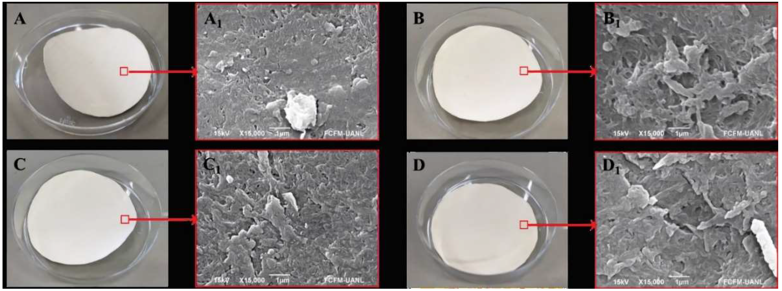
Figure 2.
XRD Spectra of Sputter-Modified membranes with ZnO at different exposure times.
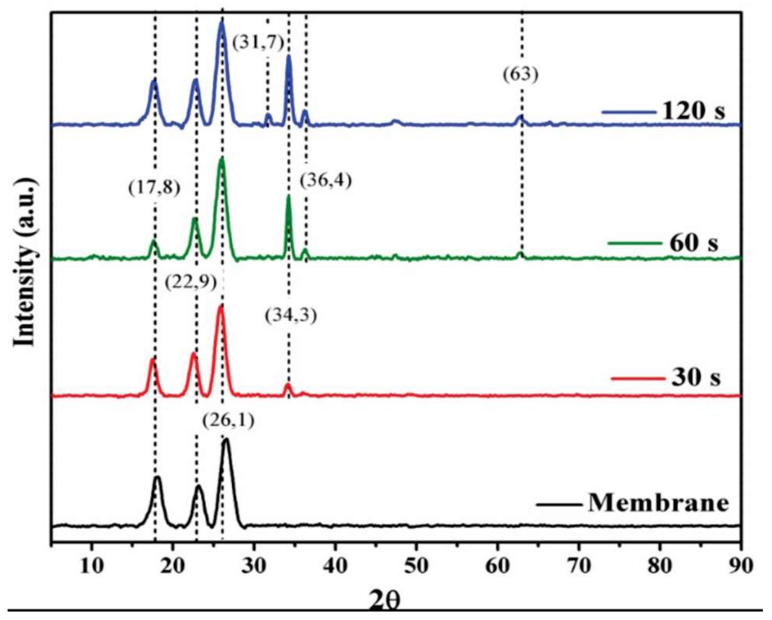
Figure 3.
Contact angles of Sputter-Modified membranes with ZnO: A) unmodified; B) 30s exposure; C) 60s exposure; D) 120s exposure.
Figure 3.
Contact angles of Sputter-Modified membranes with ZnO: A) unmodified; B) 30s exposure; C) 60s exposure; D) 120s exposure.
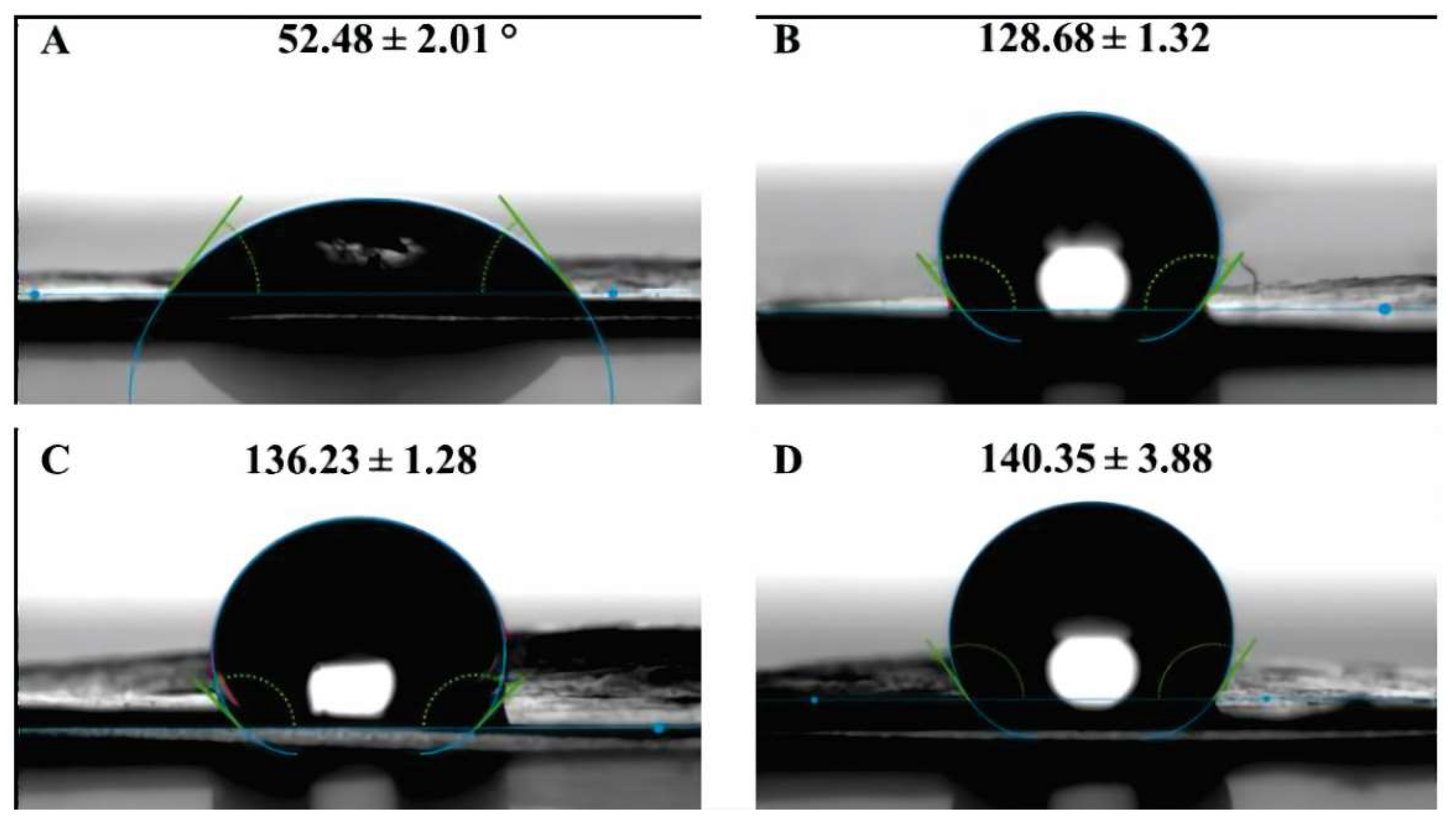
Figure 4.
AFM images of ZnO Sputter-Modified membranes: A) unmodified; B) 30s exposure; C) 60s exposure; D) 120s exposure.
Figure 4.
AFM images of ZnO Sputter-Modified membranes: A) unmodified; B) 30s exposure; C) 60s exposure; D) 120s exposure.
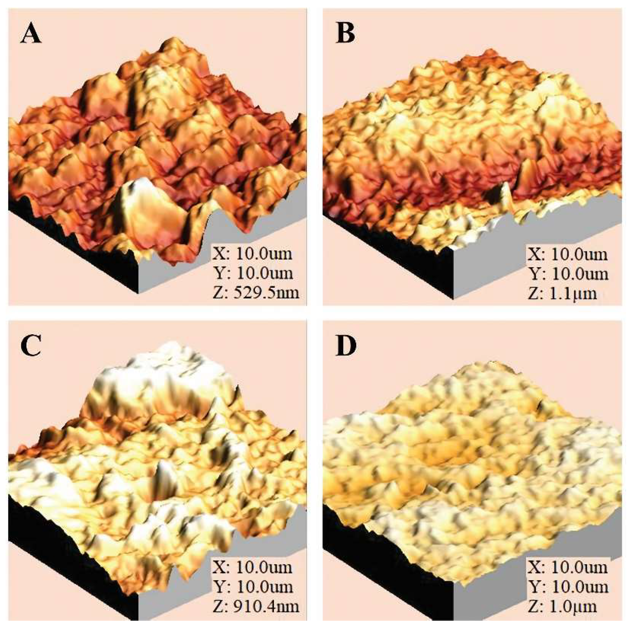
Figure 5.
Permeate flux density of membranes modified from the commercial NF90 membrane through ZnO Sputtering with exposure times of 30s, 60s, and 120s.
Figure 5.
Permeate flux density of membranes modified from the commercial NF90 membrane through ZnO Sputtering with exposure times of 30s, 60s, and 120s.
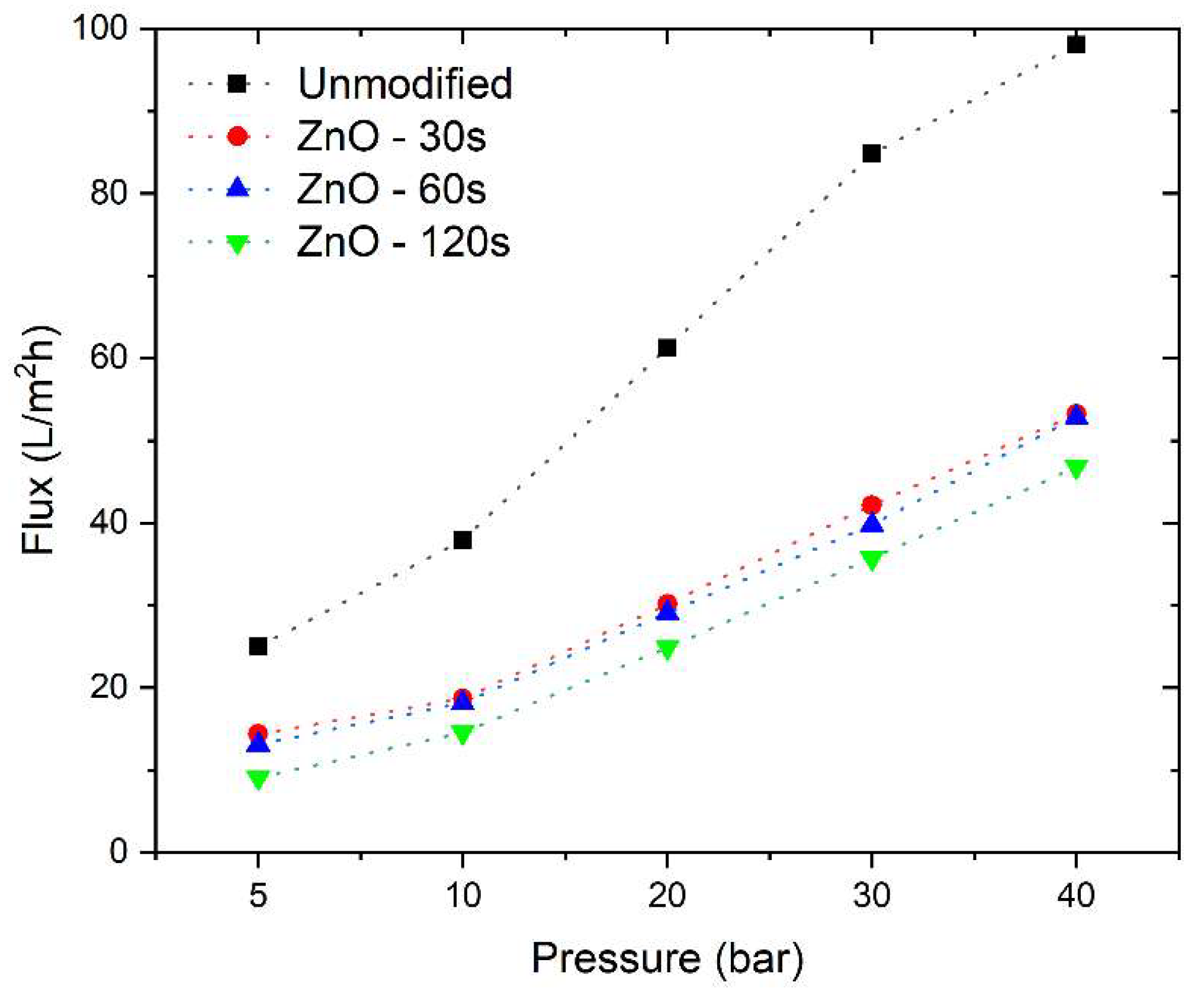
Figure 6.
Ion rejection observed as a function of operating pressure in the filtration process of a 1 g/L NaCl solution on NF90 commercial membrane modified with ZnO Sputtering at exposure times of 30s, 60s, and 120s.
Figure 6.
Ion rejection observed as a function of operating pressure in the filtration process of a 1 g/L NaCl solution on NF90 commercial membrane modified with ZnO Sputtering at exposure times of 30s, 60s, and 120s.
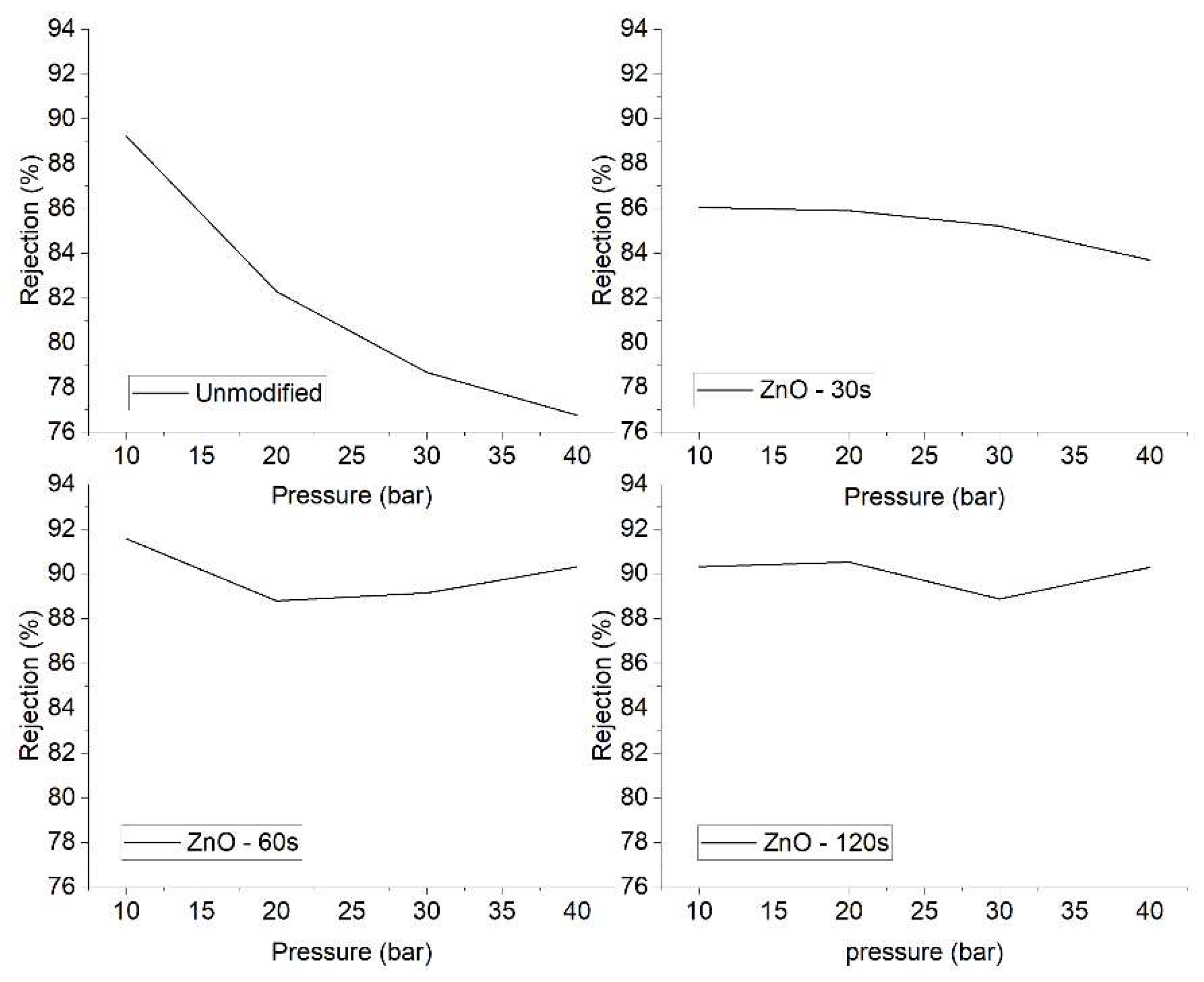
Figure 7.
Solute retention vs. permeate flow curve from experimental data and predicted results using the Spielger-Kedem Model (SKM) for unmodified NF90 and ZnO modifications of 30s, 60s, and 120s.
Figure 7.
Solute retention vs. permeate flow curve from experimental data and predicted results using the Spielger-Kedem Model (SKM) for unmodified NF90 and ZnO modifications of 30s, 60s, and 120s.
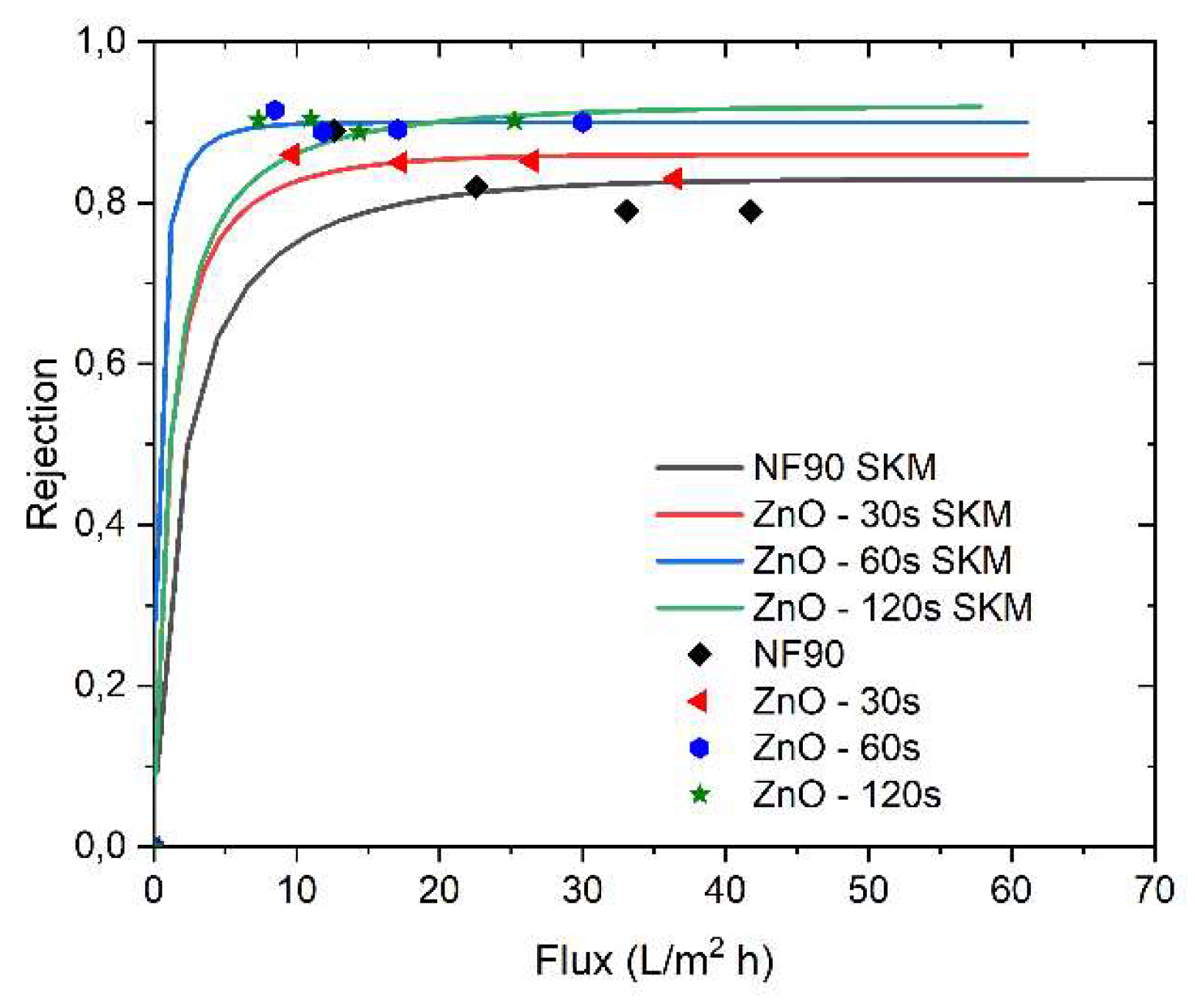

Table 1.
Roughness of the modified membranes.
| Membrane | Image size [μm] | RMS Roughness [nm] | Ra [nm] | Wenzel factor, r |
|---|---|---|---|---|
| Unmodified | 10x10 | 90.22 | 71.42 | 1.059 |
| 30s ZnO exposure | 10x10 | 230.7 | 201.1 | 1.195 |
| 60s ZnO exposure | 10x10 | 249.1 | 202.8 | 1.155 |
| 120s ZnO exposure | 10x10 | 174.0 | 144.2 | 1.096 |
Disclaimer/Publisher’s Note: The statements, opinions and data contained in all publications are solely those of the individual author(s) and contributor(s) and not of MDPI and/or the editor(s). MDPI and/or the editor(s) disclaim responsibility for any injury to people or property resulting from any ideas, methods, instructions or products referred to in the content. |
© 2024 by the authors. Licensee MDPI, Basel, Switzerland. This article is an open access article distributed under the terms and conditions of the Creative Commons Attribution (CC BY) license (http://creativecommons.org/licenses/by/4.0/).
Copyright: This open access article is published under a Creative Commons CC BY 4.0 license, which permit the free download, distribution, and reuse, provided that the author and preprint are cited in any reuse.


