1. Introduction
I refer to the mentioned bibliography for a more detailed development of the formulas used here, since I consider unnecessary to repeat fully documented previous reasonings.
Earlier analyses of the Lense Thirring (LT) effect [2] assume slowly rotating and weakly gravitational effect.
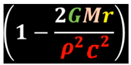
As result, the simplified formula [1] for LT precession in the “weak gravity” field for celestial bodies is reached:
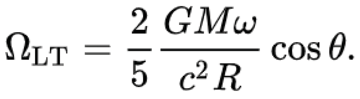
where G is the Universal Constant, M the mass, ω the rotation speed, R the radius, c the light speed and Ɵ the latitude (in our case reduced to the equator, therefore Ɵ =0).
But this simplified expression in the “weak-gravity field” is not valid for our case, because although our objects of study create a very tiny newtonian gravity effect around them, they have a high rotation speed when compared with their mass, therefore weak-field should not be applied by default. We must apply strong-field instead. We’re also going to find out such need later from a mathematical side.
For using LT in a generic way for any kind of object with any rotation speed, we’re going to use Kerr metric [4] (although our rotating object is not in vacuum, but this fact has hardly any influence over the precession rate).
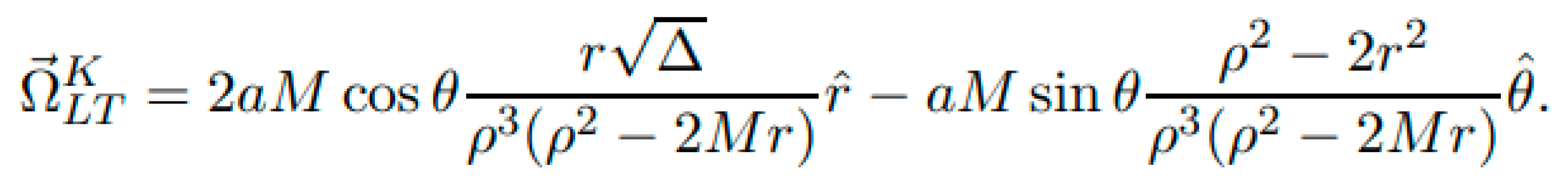
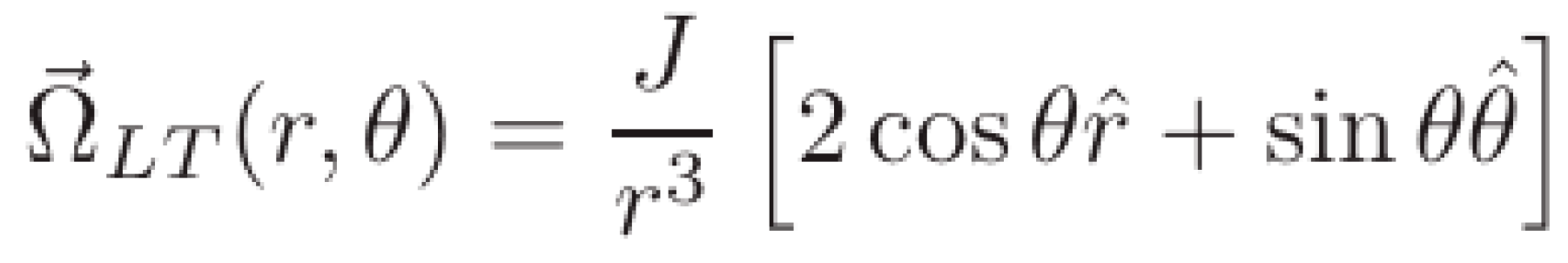
LT precession rate in Kerr spacetime & Boyer-Lindquist coordinates can be expressed as [7–9]:
where a is the Kerr Parameter, defined as

, J is the angular momentum, M the mass and c the speed of light, but usually is simplified (when applied to black holes, neutron stars … ) using c=1.
But in our case, focused to the study over small rotating objects, we must consider the real value of c.
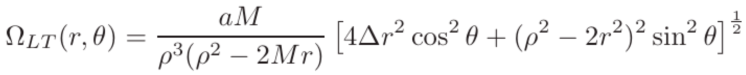
The module/magnitude of the vector (1) is our first goal. It is:
where a=J/M (known as Kerr parameter, the angular momentum per unit mass), and ϴ the collatitude, being
This is the LT precession rate in a generic way, where no weak gravity presumption has been done.
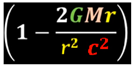
In the case that r >> a (r >> M) → the Kerr metric is almost reduced to Schwarzschild [5] metric (
, a=0). In fact the equation (1) would be reduced to the weak-field:
We’re going to use the weak field **only** when general way can’t be used due to the presence of the singularity represented by a negative value of Δ (discriminant).
I insist again in the fact that we’re going to use the a Kerr parameter in its generic form, not in its simplified form with c=1.
In our particular case, the Kerr parameter is relatively high, because J=I.ω where I is the moment of inertia and ω the angular speed and we’re managing large angular speeds and light masses. Therefore we’re going to use weak-field only when strictly necessary.
We’re going to focus calculations in Equator (for spherical objects) although the precession effect changes slightly from Equator to Poles, as we’re going to study later.
2. Scope of Application To Rotating Objects
To apply LT effect to any rotating object, we’re going to base our work on the premise that the concavity produced by a celestial body over any object can be counteracted by the convexity in spacetime produced by the object speed, lineal or angular (just as exposed and proven by Zero Gravity Theory [
10]). Then Gravity could be also counteracted by the spacetime convexity created by LT effect (when the object spins counter-clockwise) or generated/reforced by the spacetime concavity created by LT effect (when the objects spins clockwise).
With the goal of knowing the real impact of LT over different kind of objects and spin speeds, we’re going to apply the formula (1) at first time to very small objects (with morphology of disk) which were used along of most of my Zero Gravity [
10] experiments. Then we’re going to apply it to more large objects with different morphologies (sphere, disk), sizes, materials and rotation speeds.
I would like to remark that the sign of Δ (discriminant) parameter (3) deeply determines the range of application of the formula (1) for not-weak fields. That is, when M*r > (r2+a2) then Δ < 0 . This scenario is more suitable for low values of a and for denser materials. In such cases we’re going to apply weak-field solution.
In fact an strict application of such range ( Δ > 0 ) would limit the application of Kerr formulas to an specific and bounded interval of rotation speeds.
From the obtained results (exposed in the following chapter) a close relation (especially for light materials) can be found among the range of rotation speed needed for applying Zero Gravity effect (ZG) and the range of rotation speed needed for applying LT effect.
Applying simultaneously both effects (ZG and LT), space crafts based on both technologies could achieve partial zero gravity, total zero gravity and anti gravity effects of different magnitudes.
3. Application to Different Morphologies, Sizes, Rotation Speeds and Kind of Materials.
I’ve built simple Python programs to show the results of the Theory for different morphologies, sizes and kind of materials.
3.1. Disks of Different Materials (Cardboard, Wood, PVC, Aluminum, Steel, Carbon Fiber).
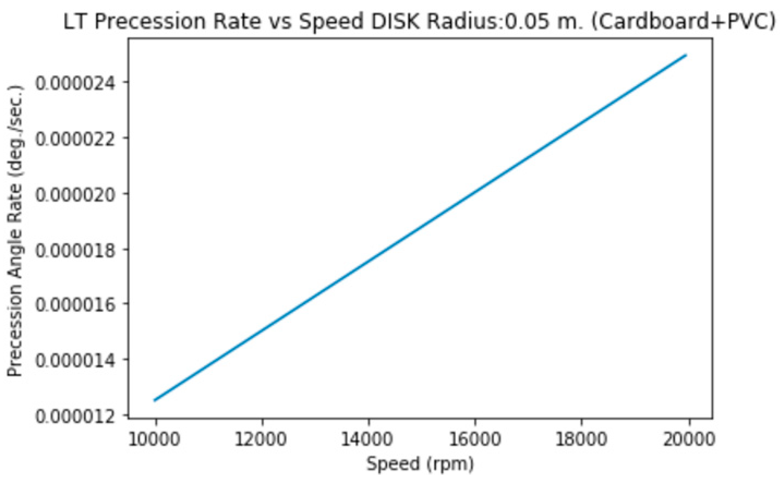
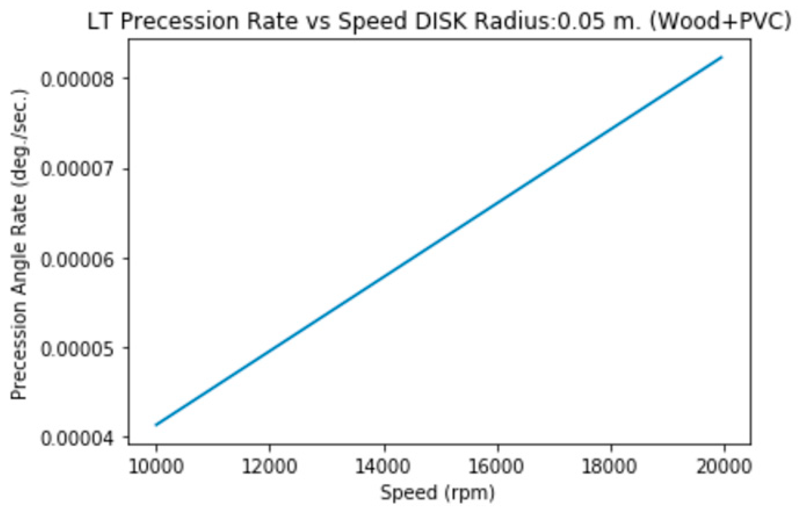
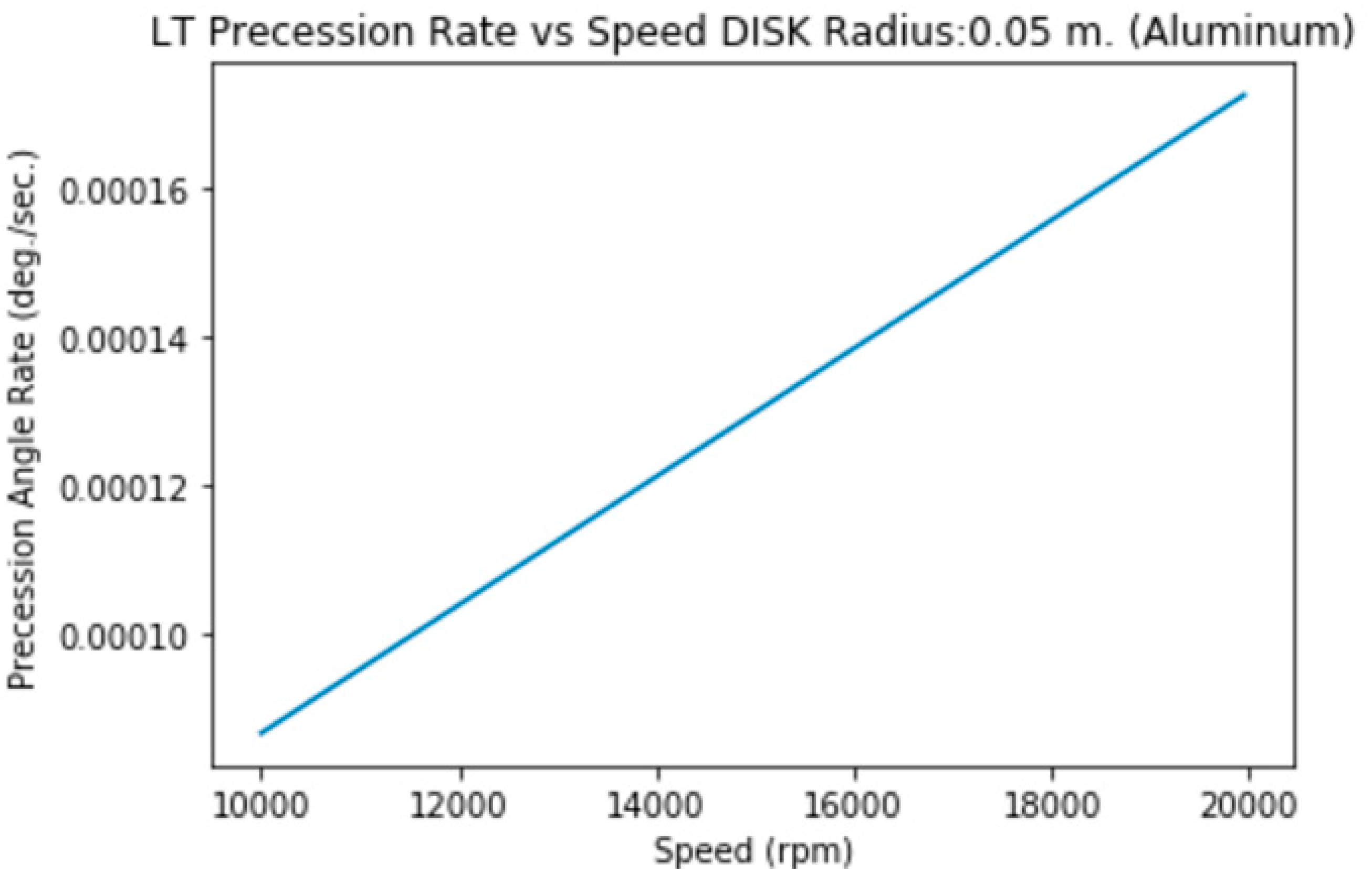
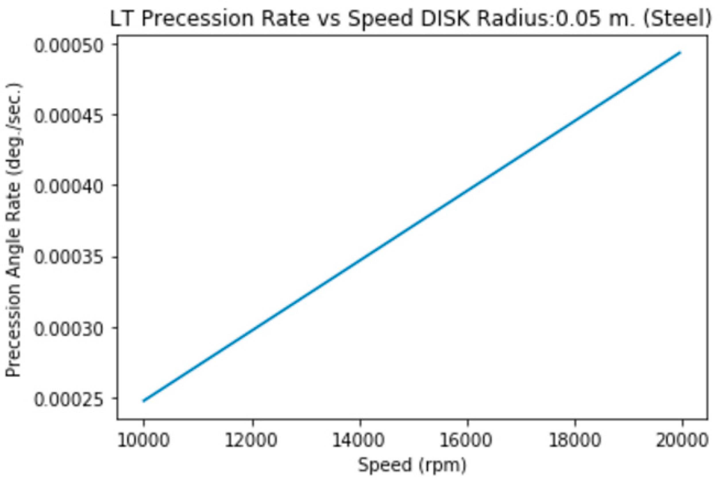
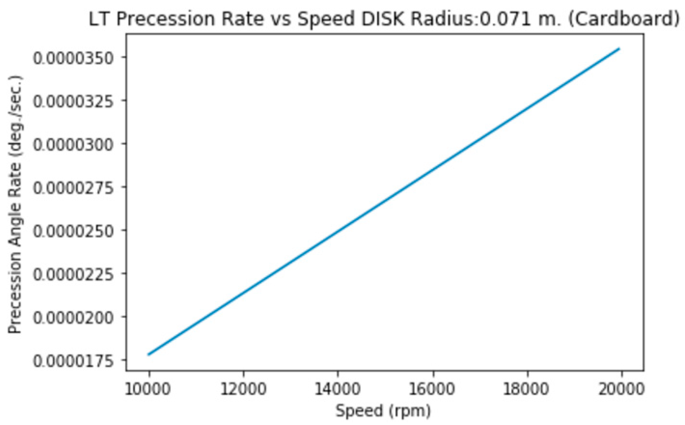
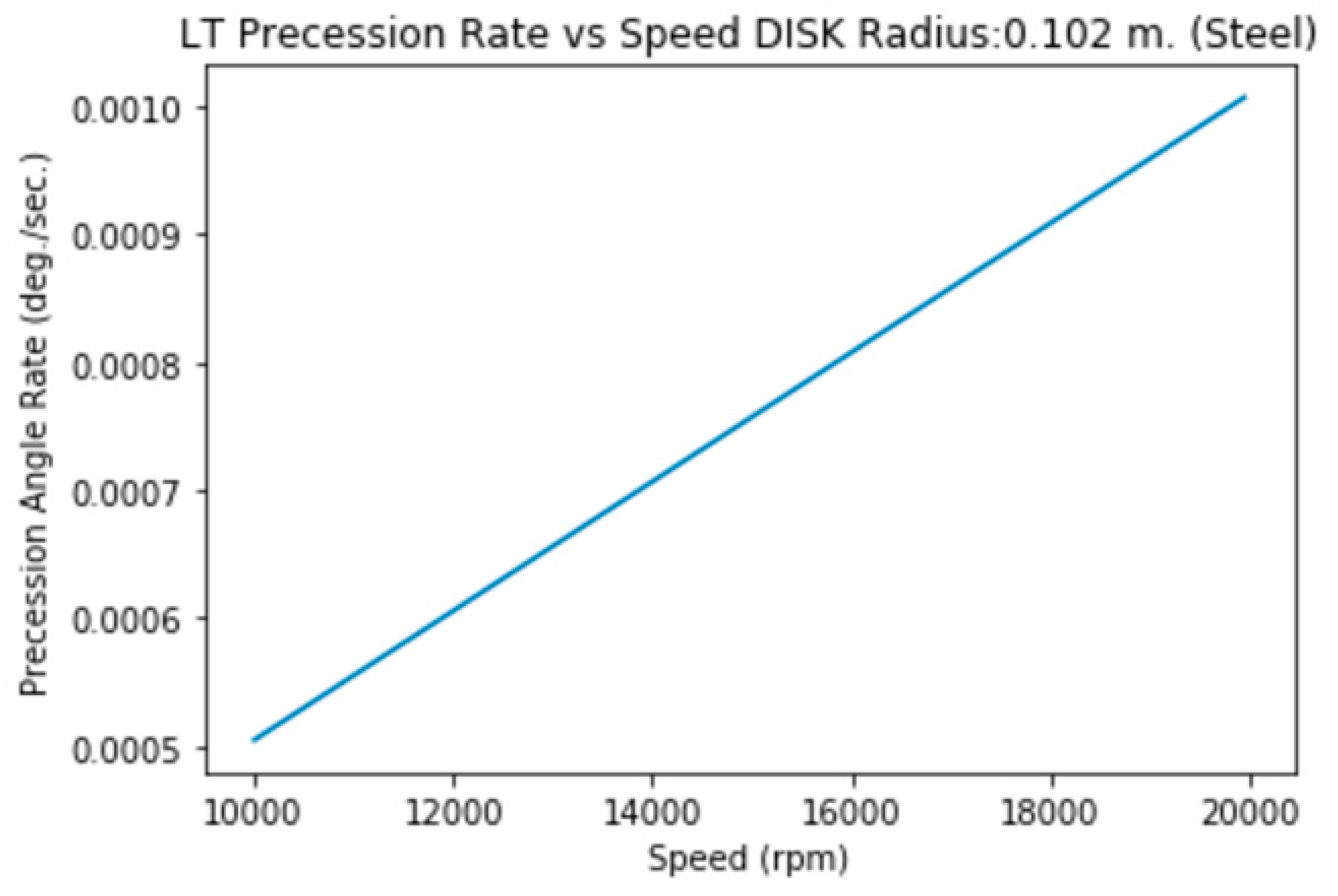
Just I told before, I’ve applied the Theory at first time to small objects that were used to prove my Zero Gravity Theory. These light objects with disk morphology have a high rotation speed (from 10.000 rpm to 20.000 rpm), radius from 5 cm. to 10 cm. and very slightly thickness (from 2 to 3 mm.).
For such cases, I (moment of inertia of a disk)=1/2*M*R2. Therefore simplified a Kerr parameter (J/M) =1/2*R2*ω , being ω values included between 10.000 rpm*2* П /60=1047 rad/s and 20.000 rpm*2* П /60=2094 rad/s.
We’re going to use the Kerr metric also for disk morphology taking on account that a disk could be simplified as a slice of mass at the equator, with the poles flattened so the latitude is reduced to a very small range of angles.
In other words: we’re going to apply the formulas for the sphere but reduced to the equator.
3.1.a1. Disk of Radius=5 cm., Mass=5 g. (Cardboard+PVC)
3.1.a2. Disk of Radius=5 cm., Mass=11.3 g. (Wood+PVC)
3.1.b. Disk of Radius=5 cm., height=2 mm. (Aluminum)
3.1.c. Disk of Radius=5 cm., height=2 mm. (Steel)
3.1.d. Disk of Radius=7.1 cm., Mass=9.3 g. (Cardboard)
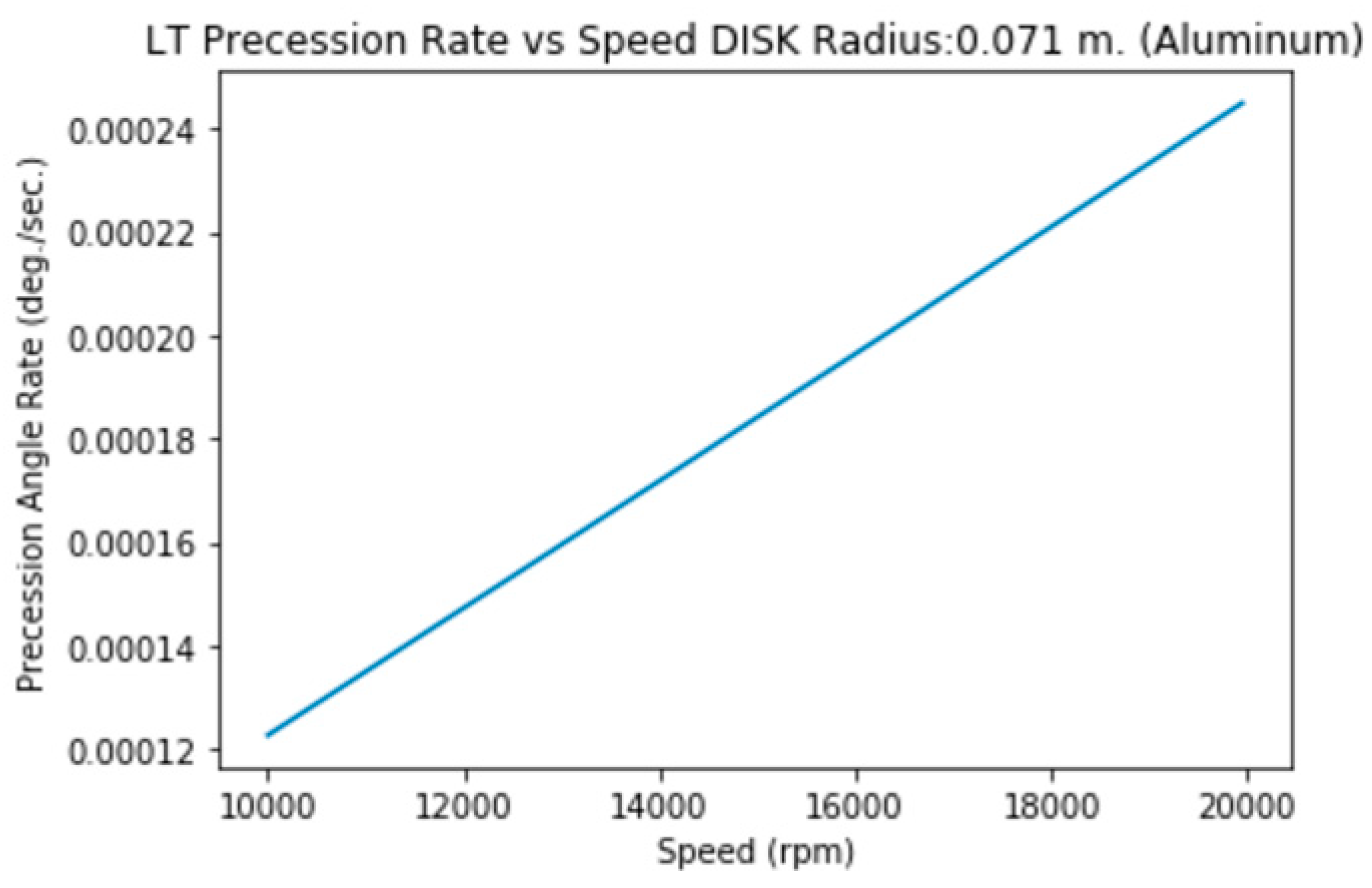
3.1.e. Disk of Radius=7.1 cm., height=2 mm. (Aluminum)
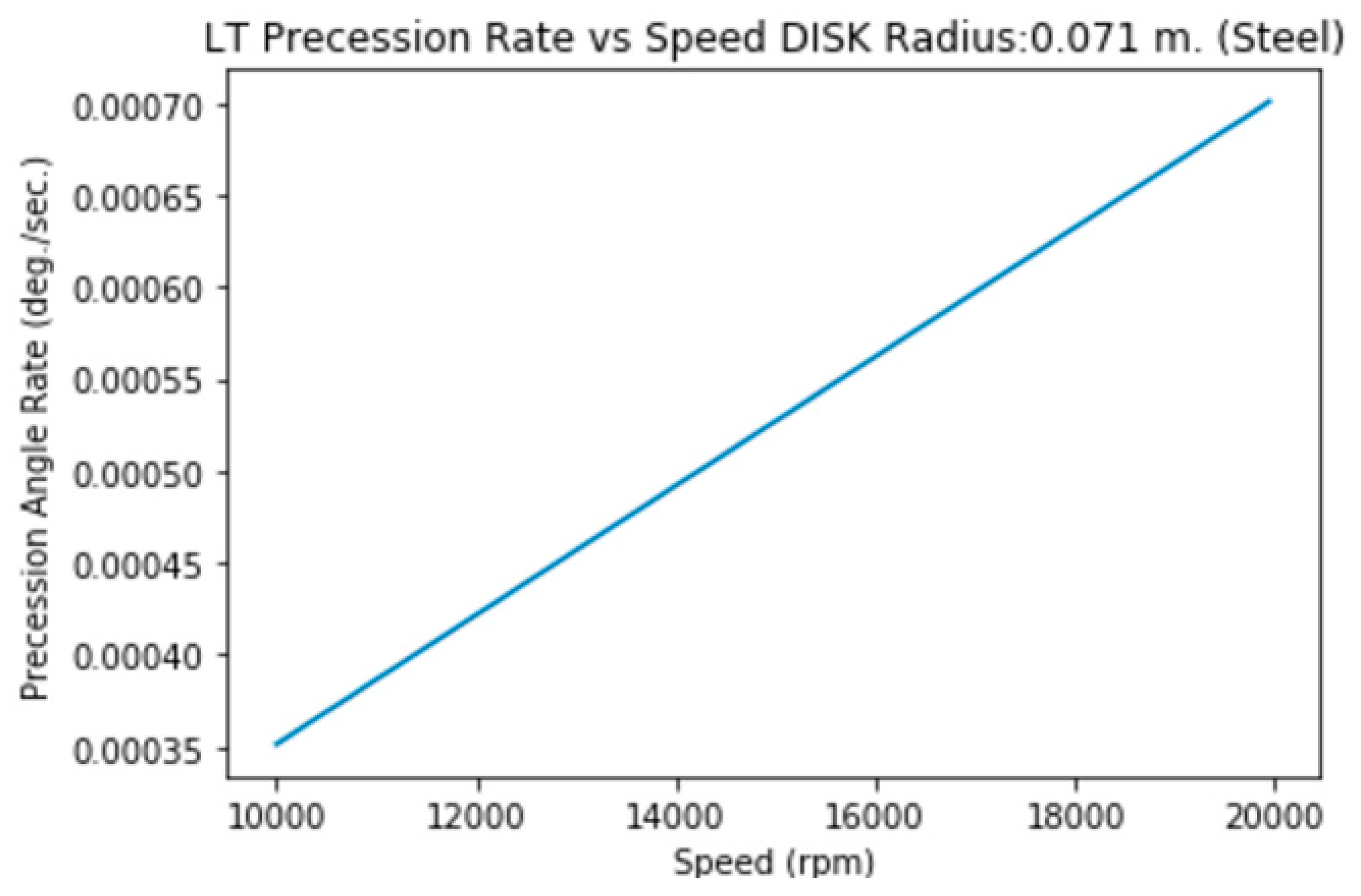
3.1.f. Disk of Radius=7.1 cm., height=2 mm. (Steel)
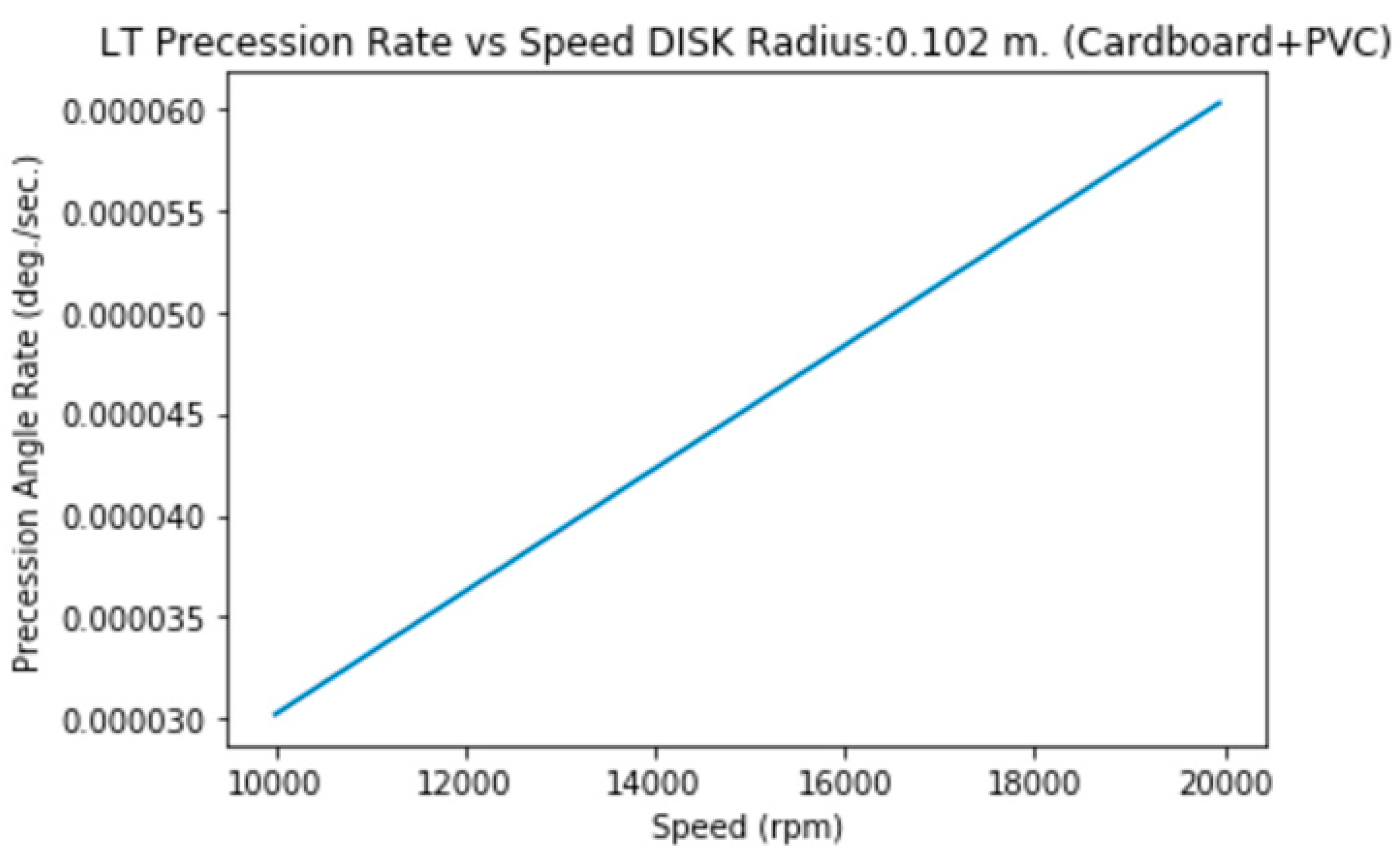
3.1.g. Disk of Radius=10.2 cm., Mass=19.2 g.
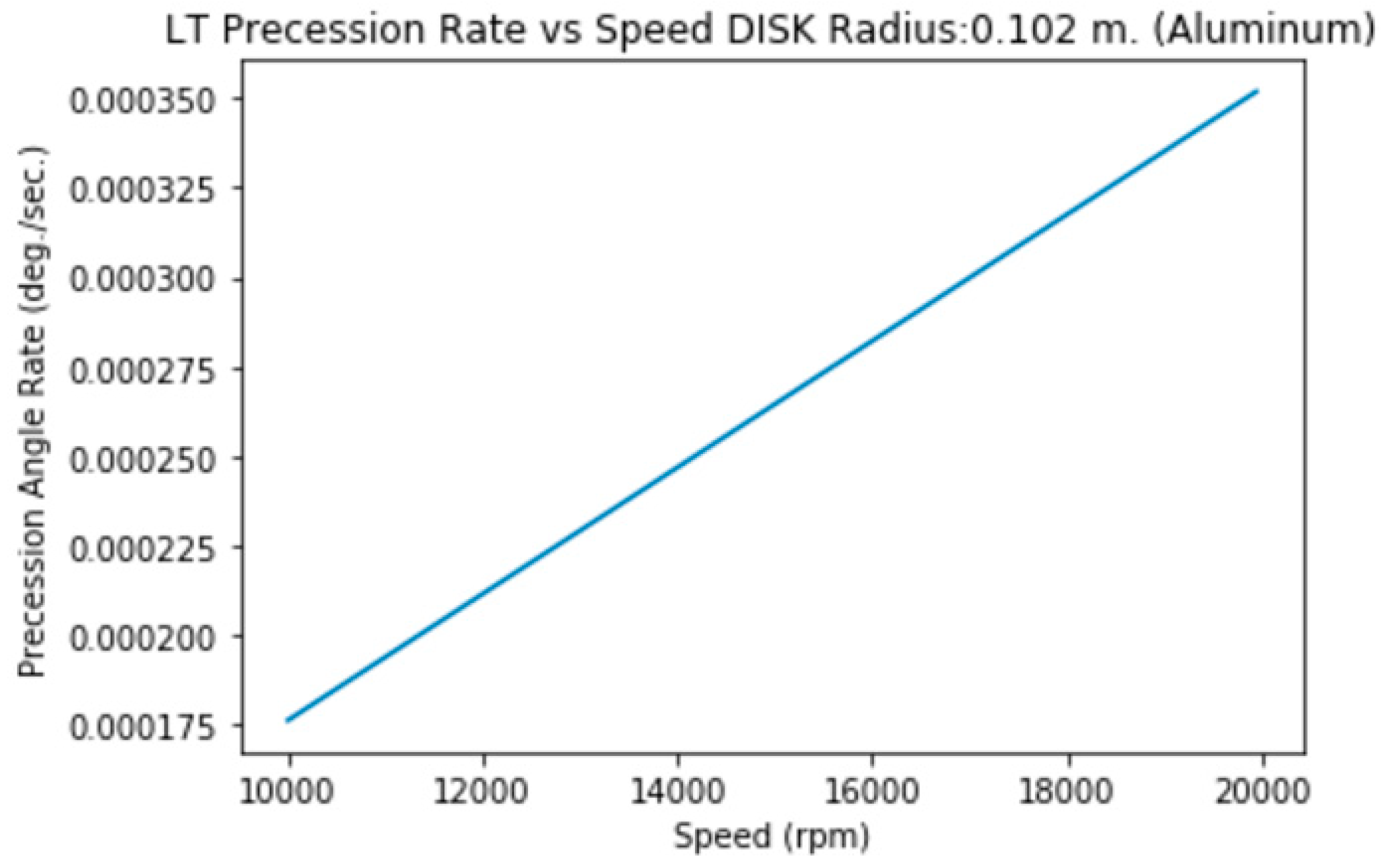
3.1.h. Disk of Radius=10.2 cm., height=2 mm. (Aluminum)
3.1.i. Disk of Radius=10.2 cm., height=2 mm. (Steel)
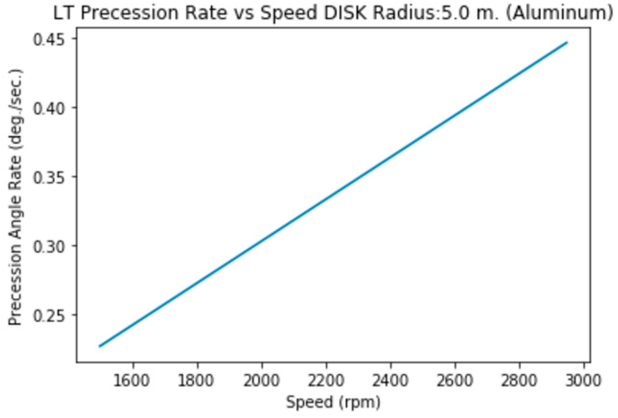
3.1.j.a. Disk (solid) of Radius=5 m., Height= 2m. (Aluminum)
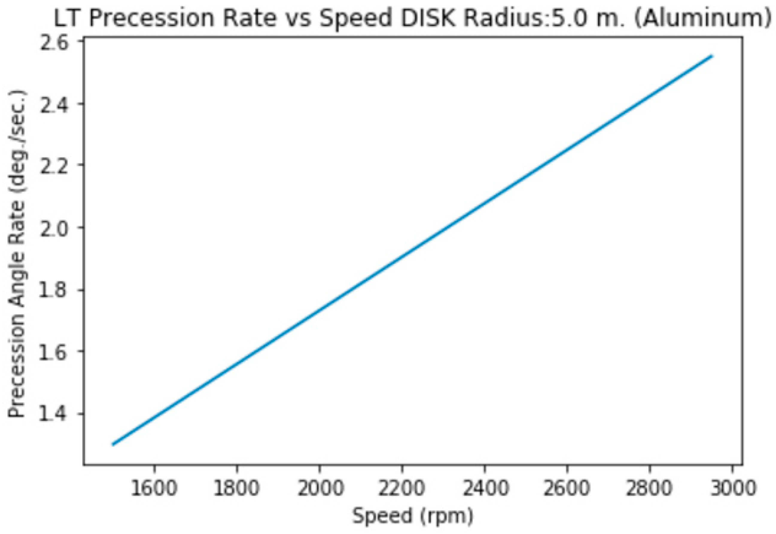
3.1.j.b. Disk (hollow) of Radius=5 m., Height= 2m. (Aluminum)
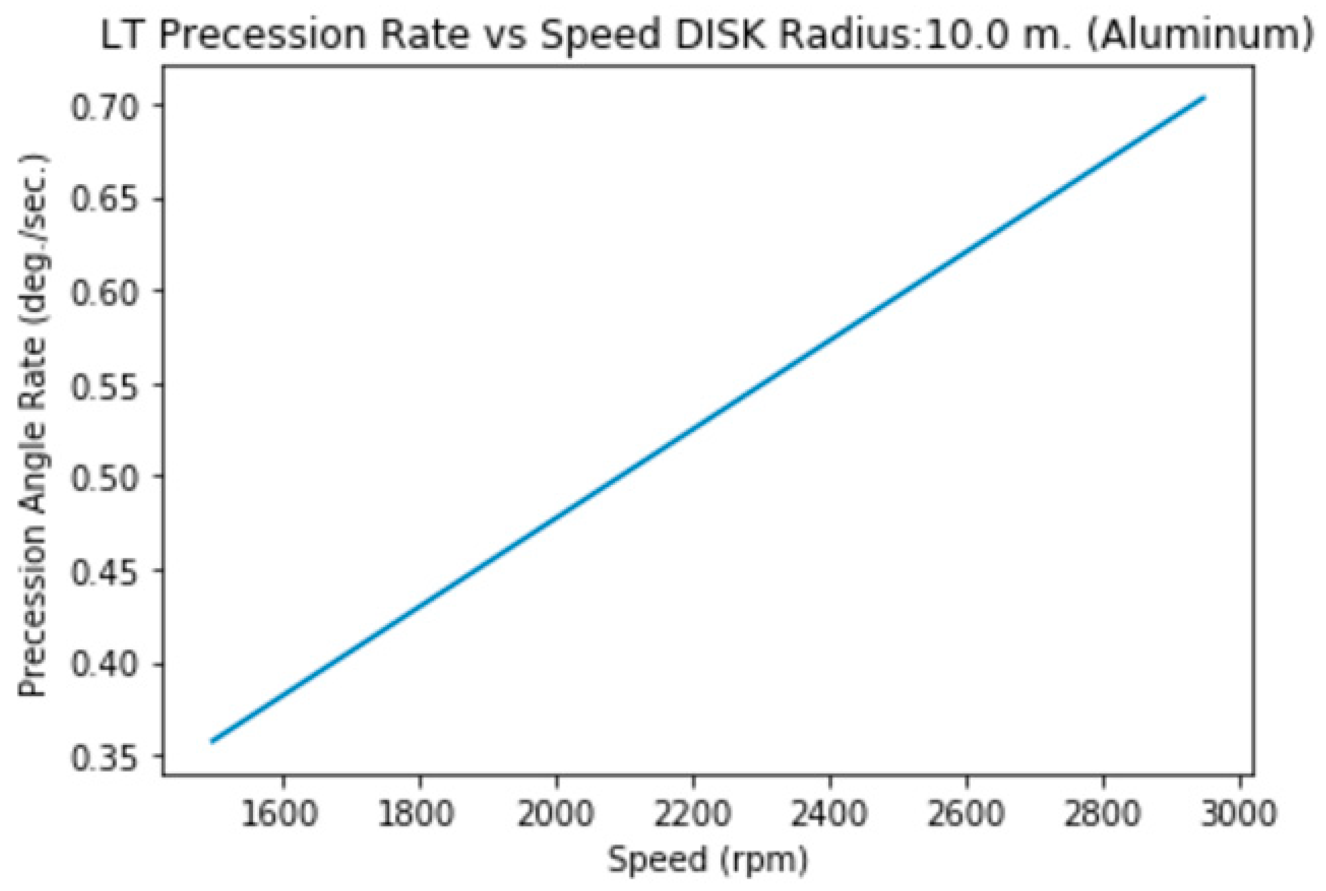
3.1.k.a. Disk (solid) of Radius=10 m., Height= 2m. (Aluminum)
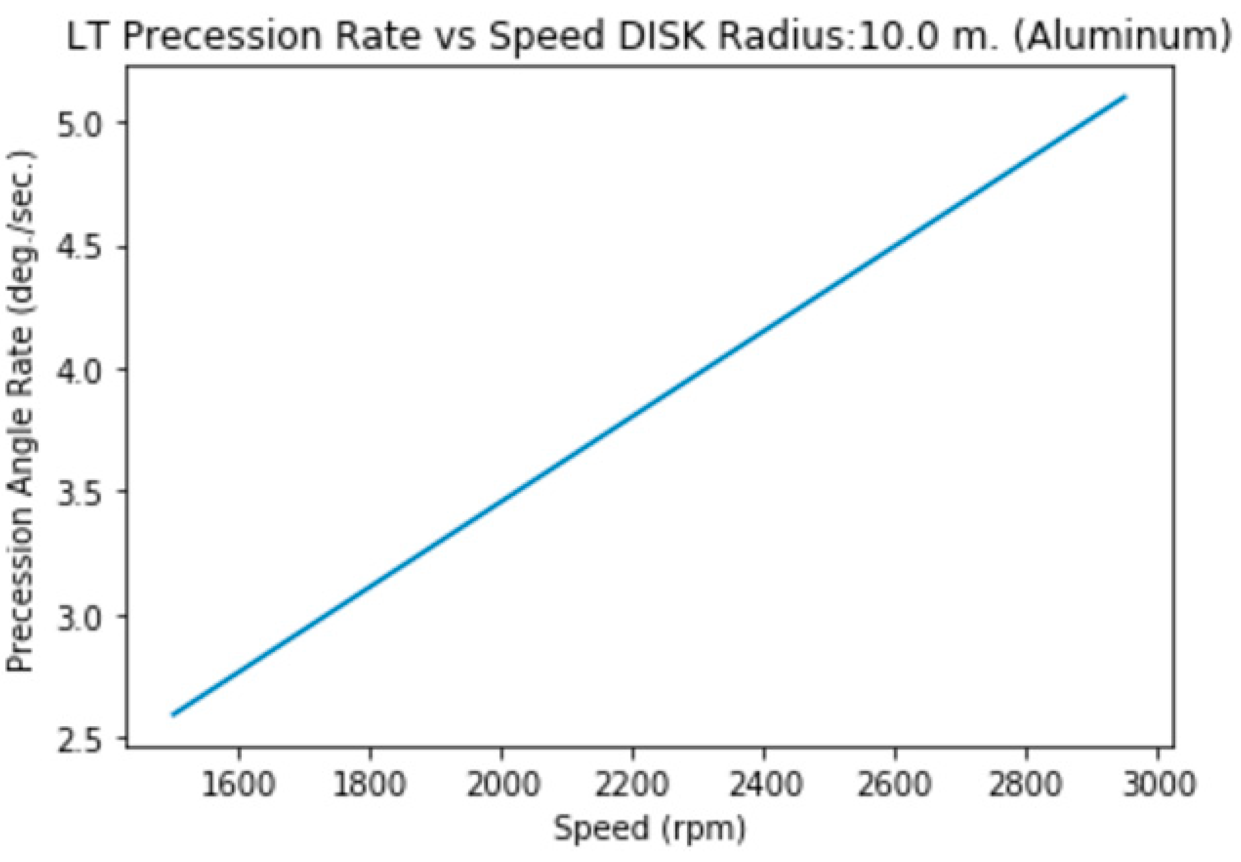
3.1.k.b. Disk (hollow) of Radius=10 m., Height= 2m. (Aluminum)
3.1.l.a. Disk (solid) of Radius=20 m., Height= 2m. (Aluminum)

3.1.l.b. Disk (hollow) of Radius=20 m., Height= 2m. (Aluminum)

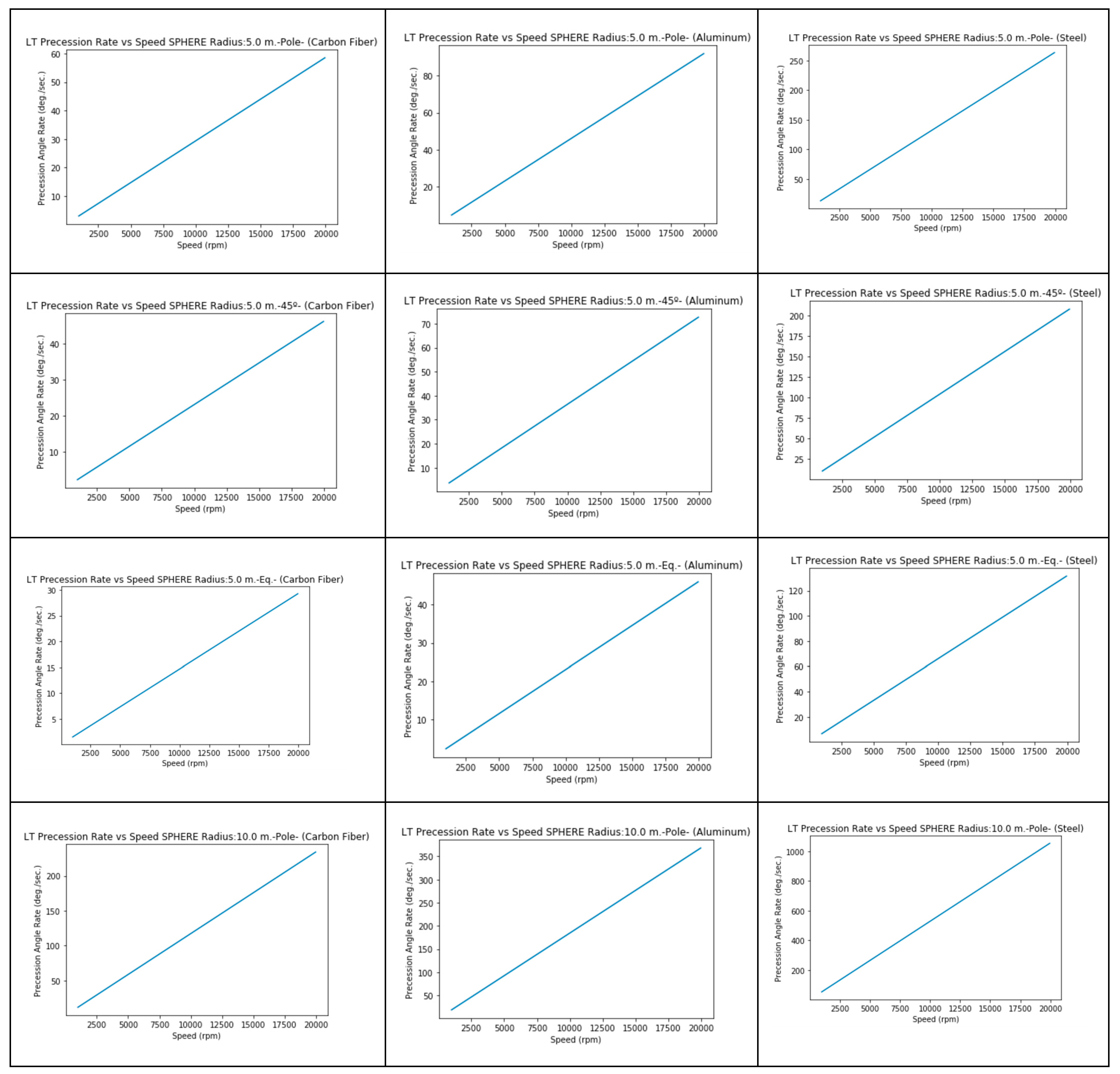
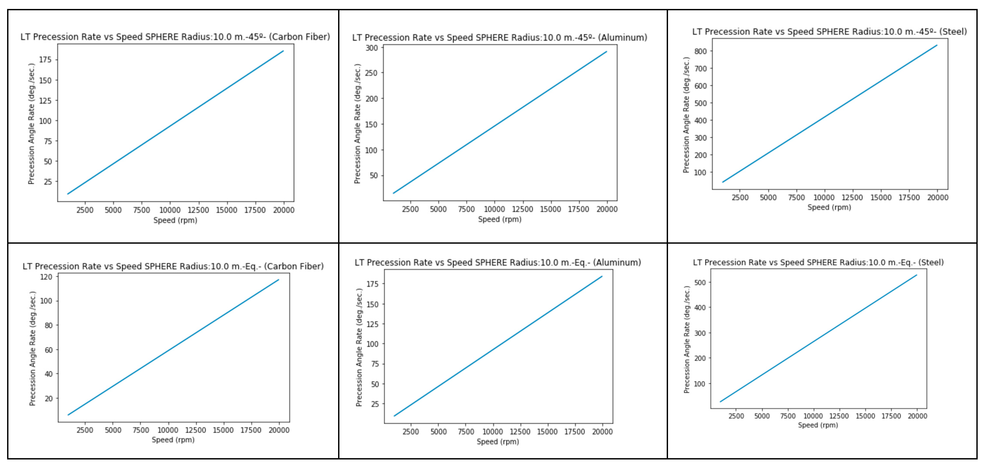
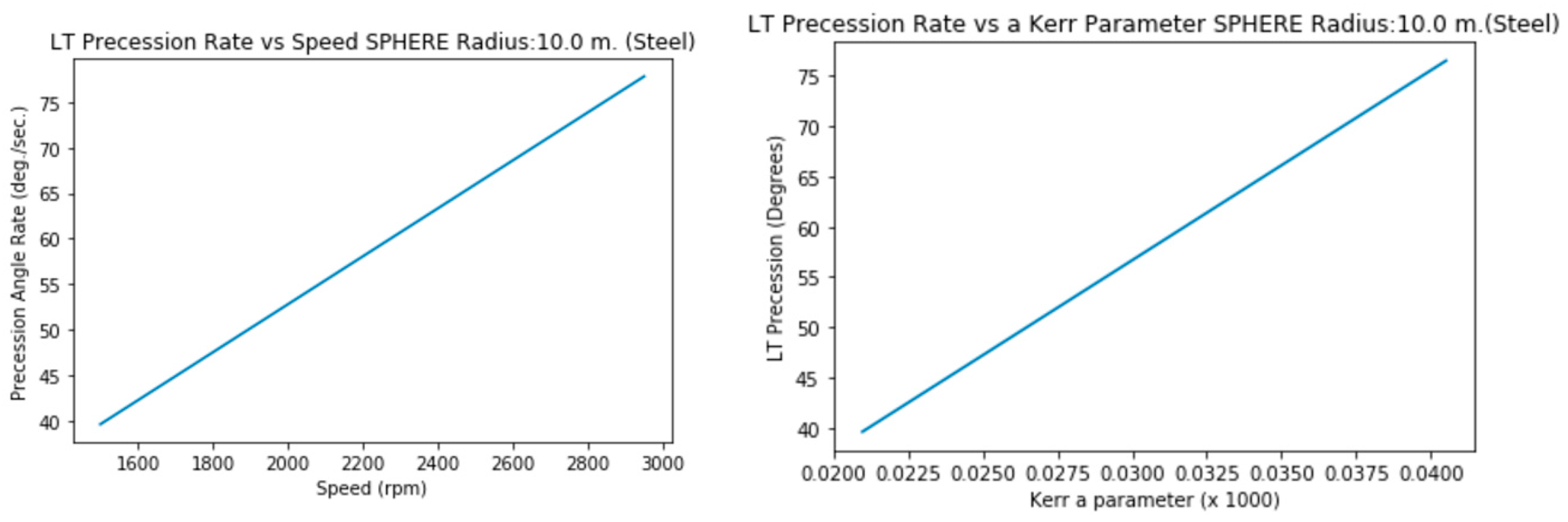
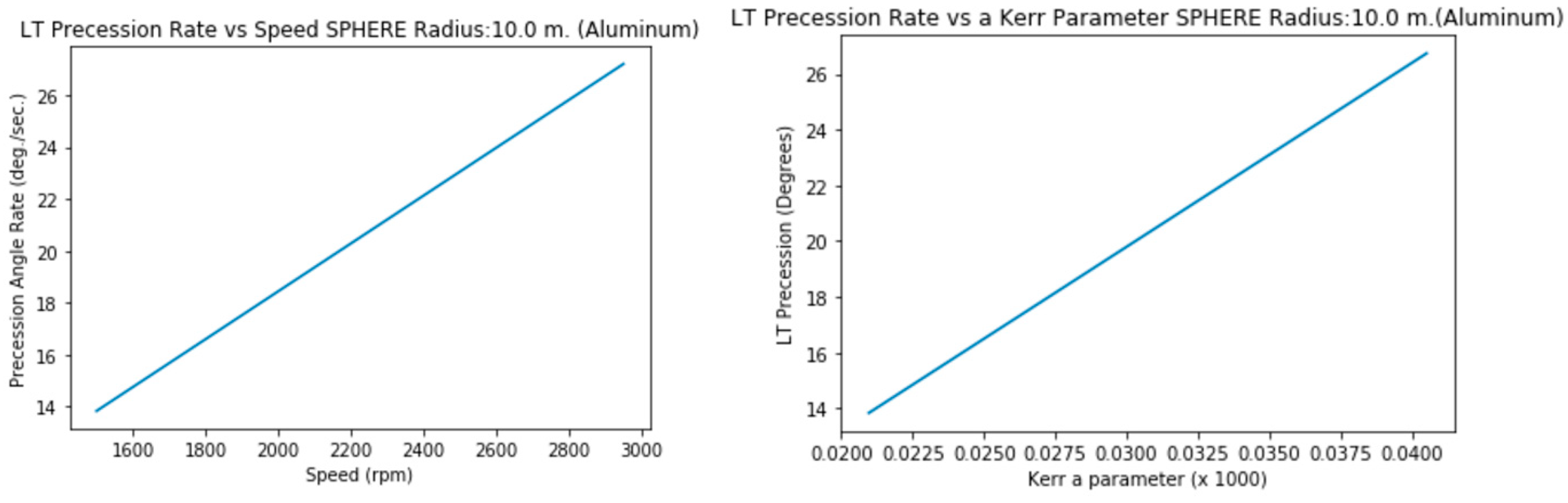
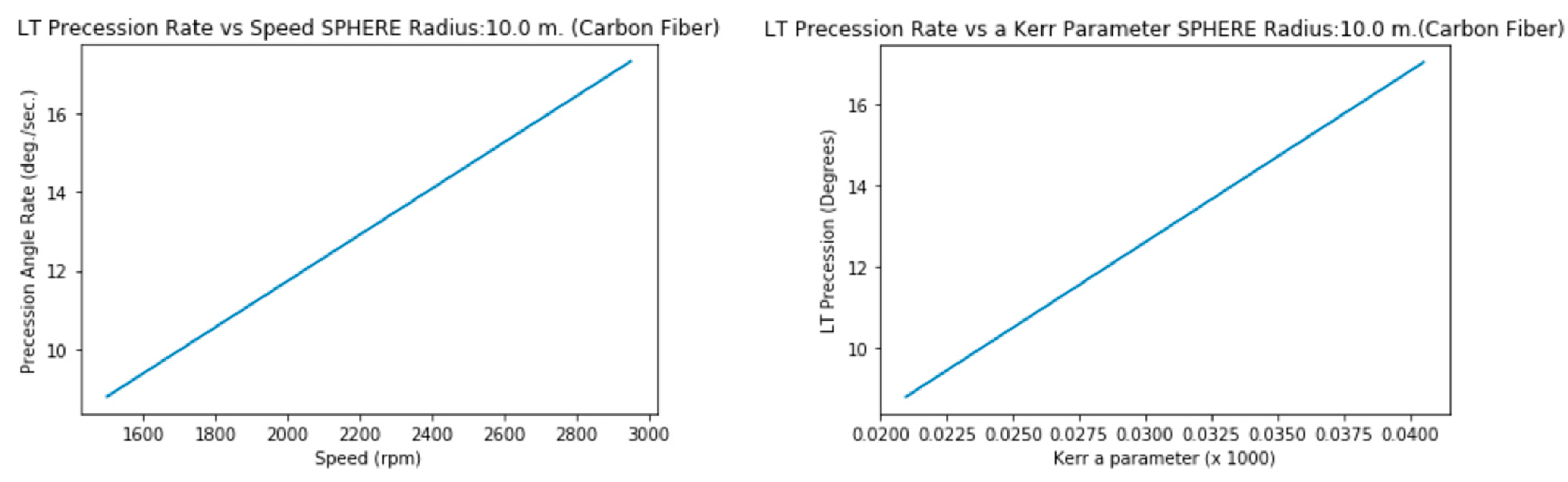
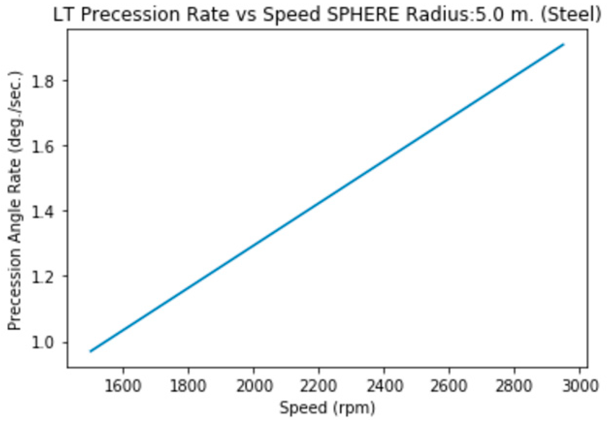
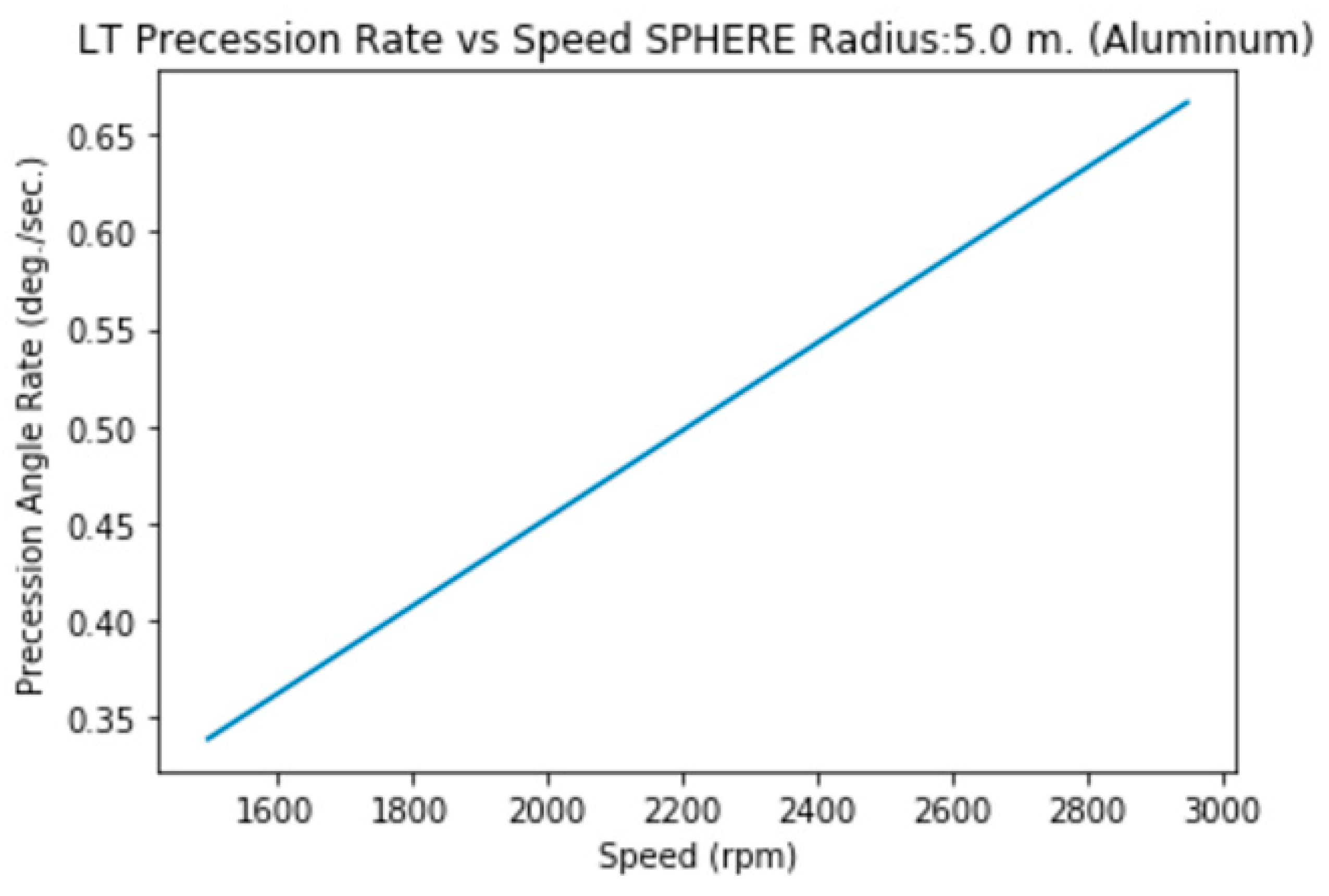
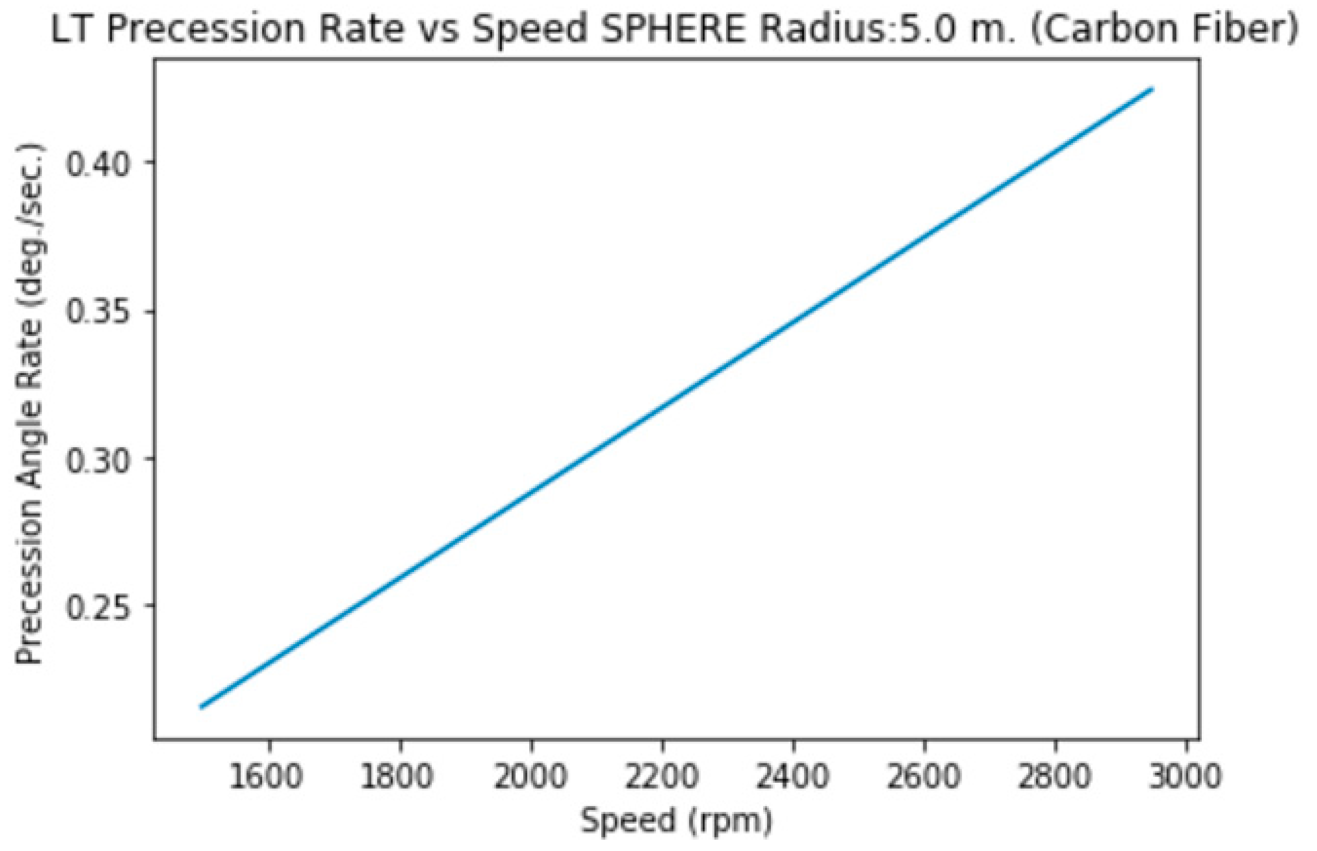
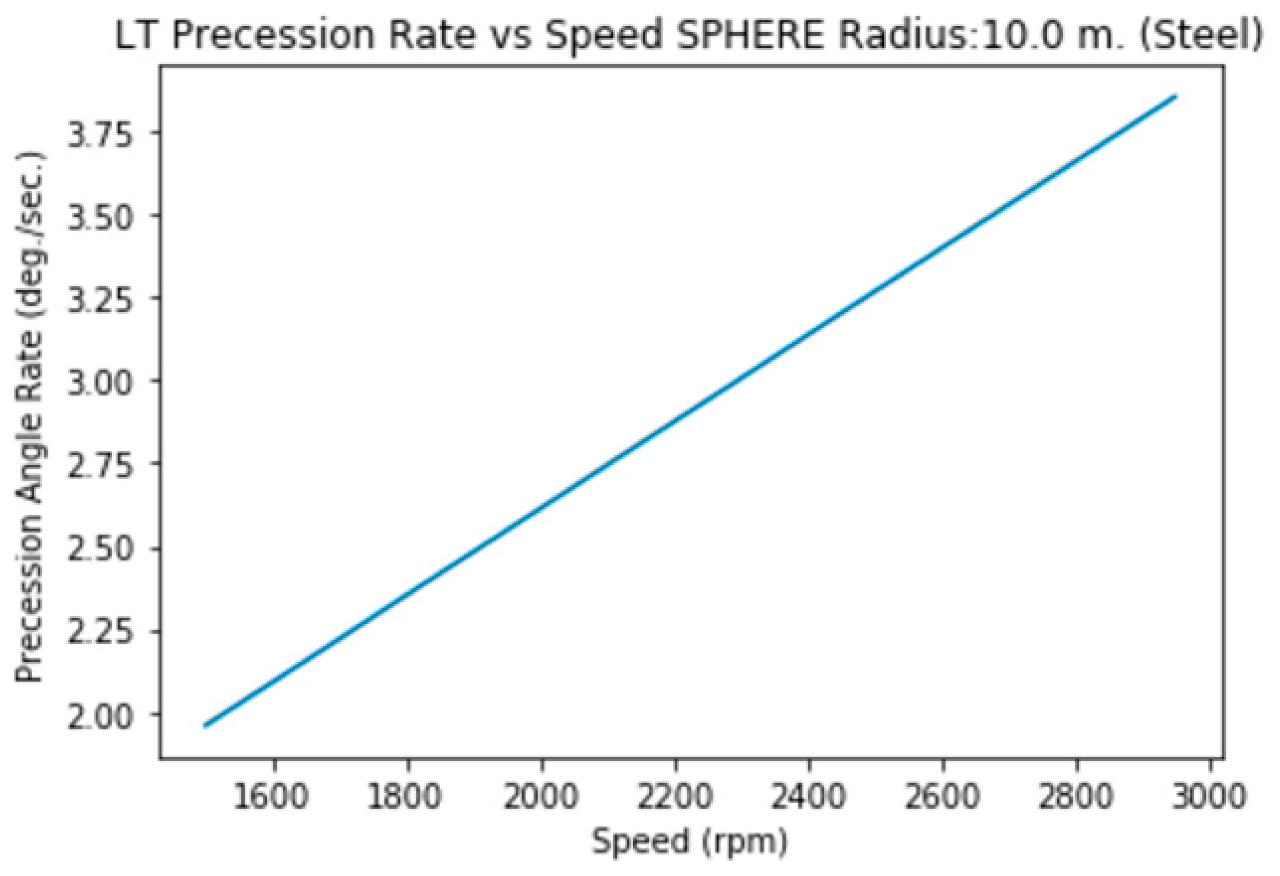
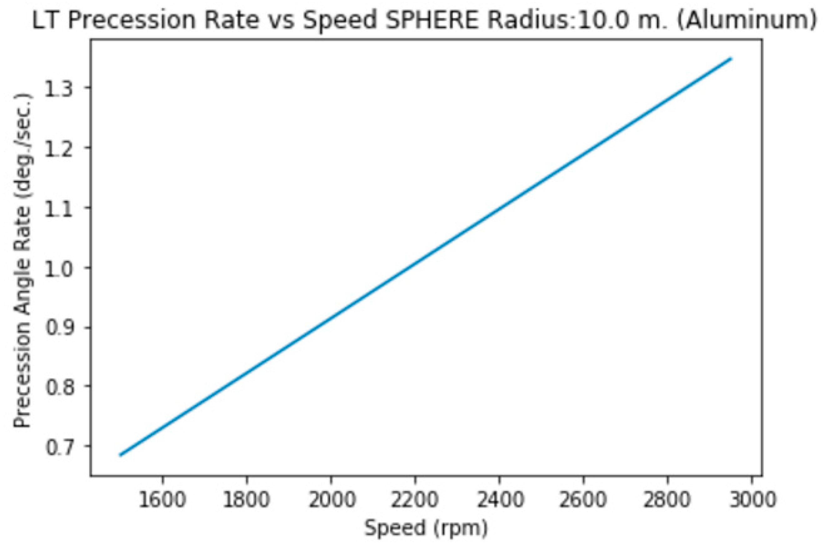
3.2. Spheres (Equator)
In this case, I (Inertia momentum)=2/5*M*R2 (solid), 2/3*M*R2 (hollow).
Therefore a Kerr parameter (solid)=J/(M*c)=2/5*R2*ω/c
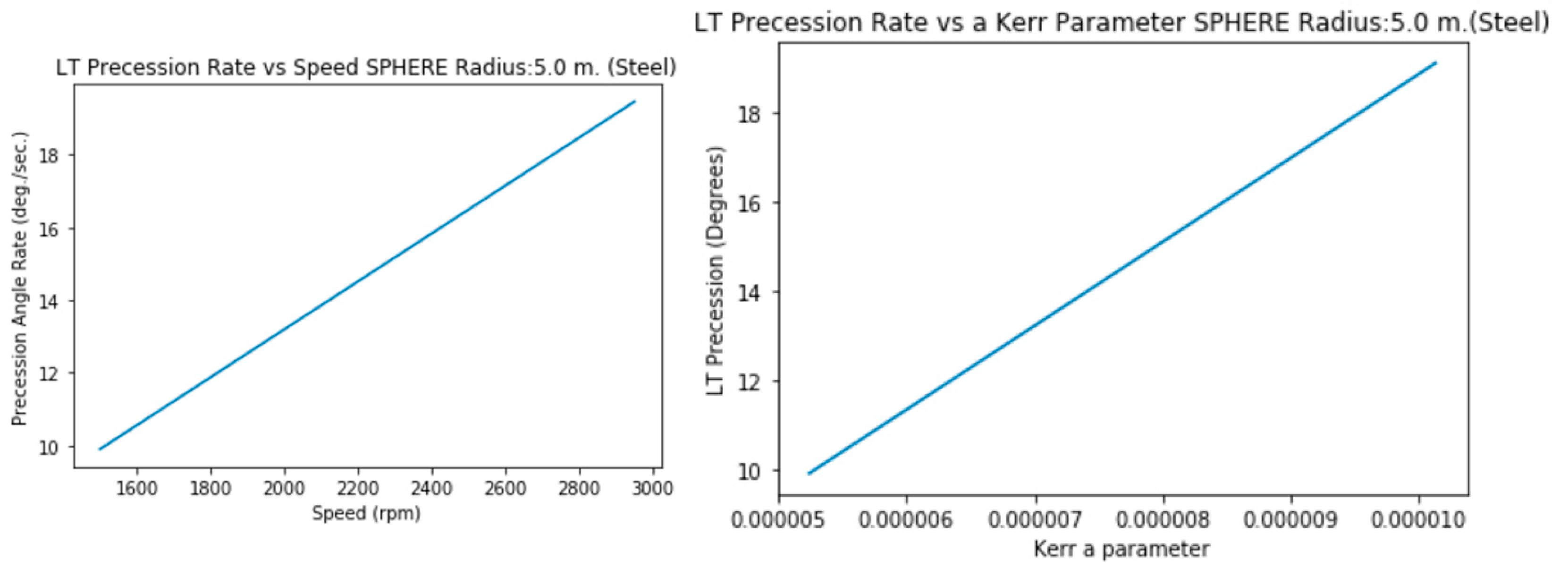
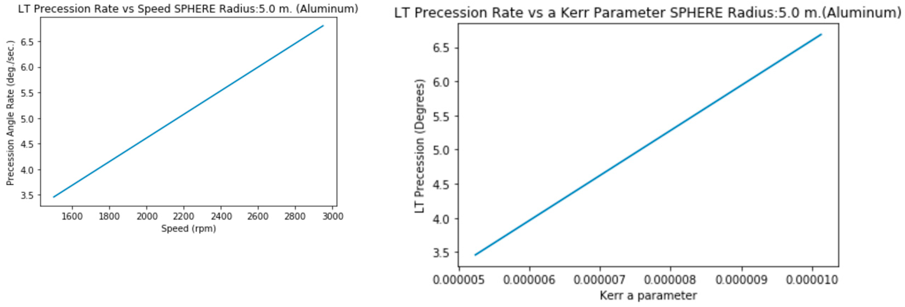
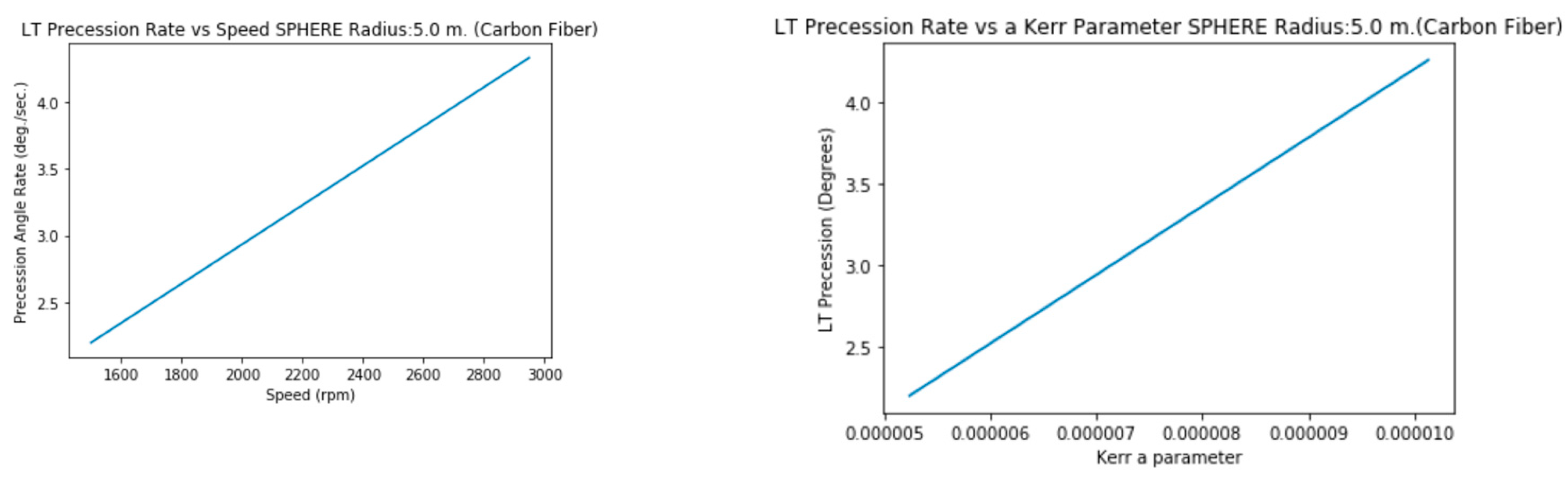
Graphics show not only Precession vs Speed but Precession vs a (not simplified) Kerr Parameter.
3.2.a. Radius 5 m. (Steel, solid)
3.2.b. Radius 5 m. (Aluminum,solid)
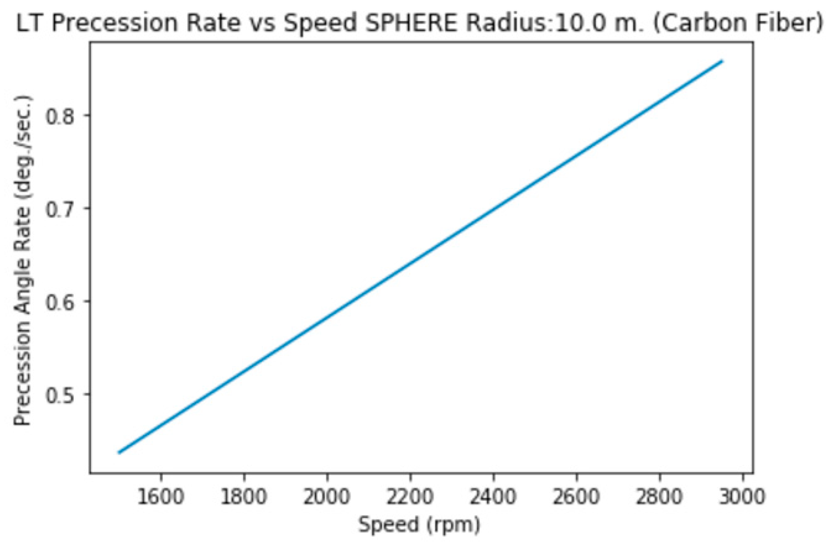
3.2.c. Radius 5 m. (Carbon Fiber, solid)
3.2.d. Radius 10 m. (Steel, solid)
3.2.e. Radius 10 m. (Aluminum, solid)
3.2.f. Radius 10 m. (Carbon Fiber, solid)
3.2.g. Radius 5 m. (Steel, hollow)
3.2.h. Radius 5 m. (Aluminum, hollow)
3.2.i. Radius 5 m. (Carbon Fiber, hollow)
3.2.j. Radius 10 m. (Steel, hollow)
3.2.k. Radius 10 m. (Aluminum, hollow)
3.2.i. Radius 10 m. (Carbon Fiber, hollow)
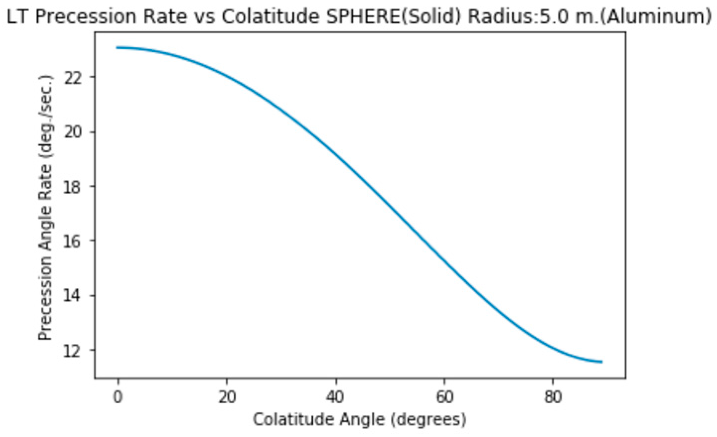
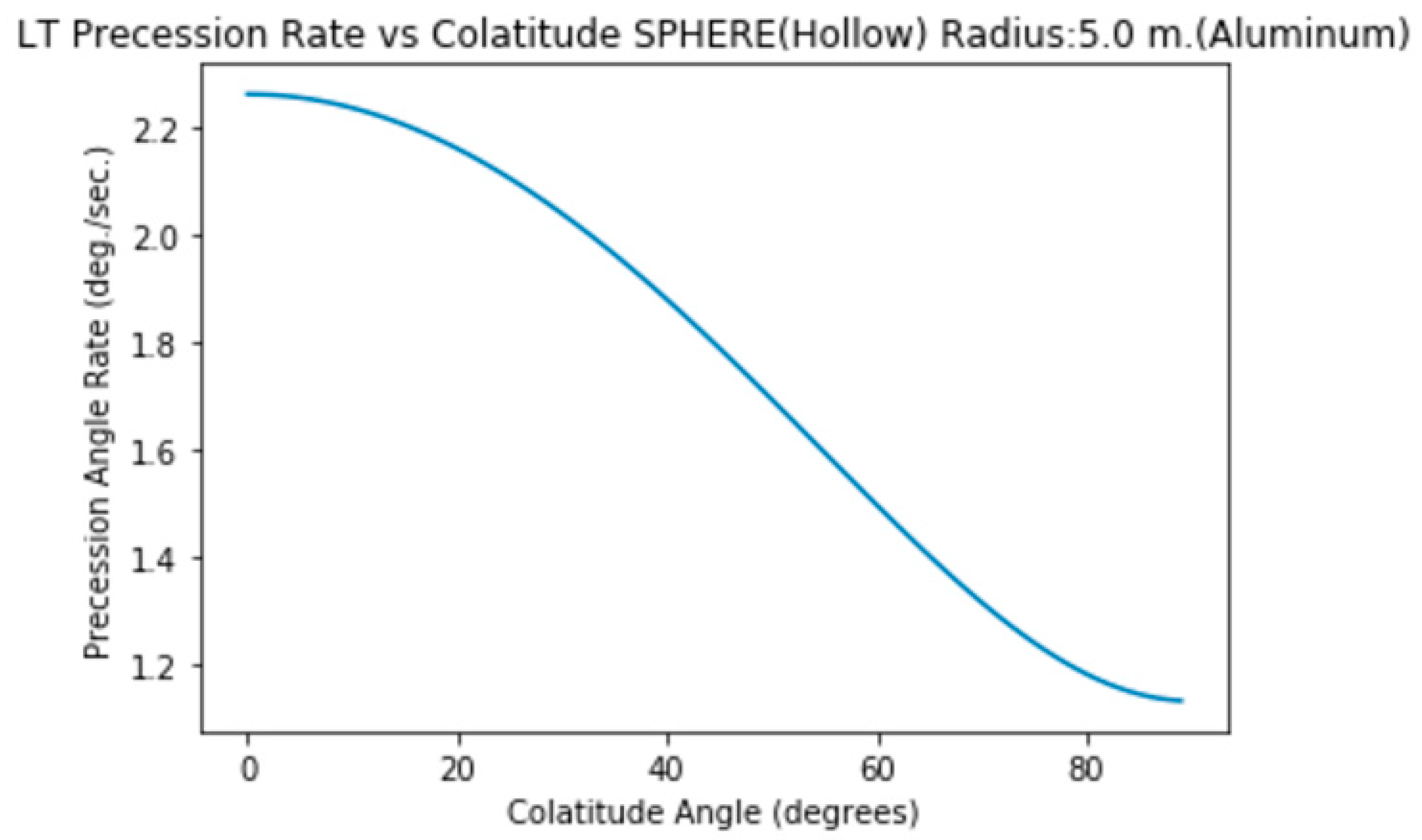
4. Precession Rate vs Colatitude Angle
Speed: 5000 rpm
5. Precession Rate (Solid Sphere) vs Colatitude & Material
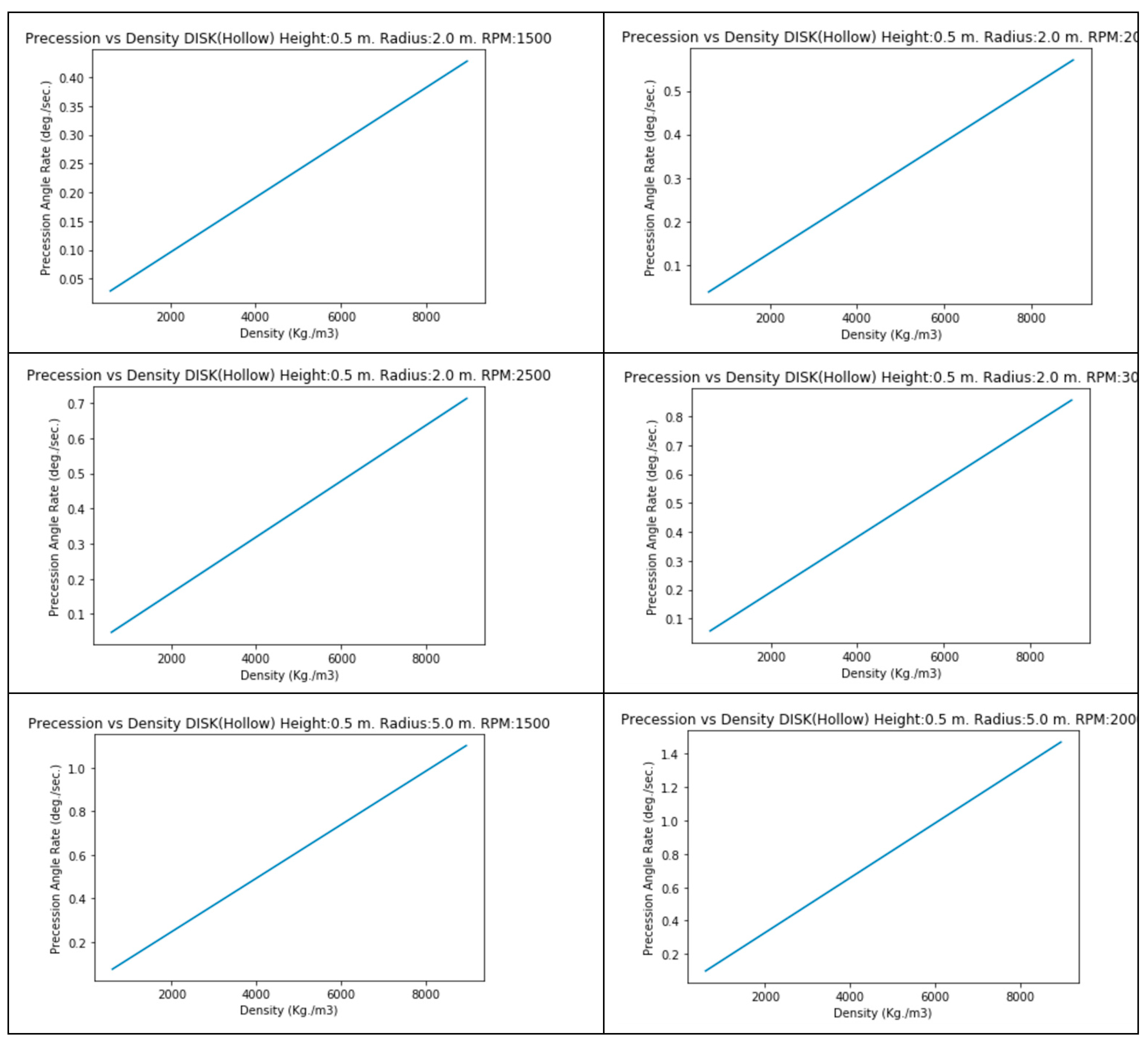
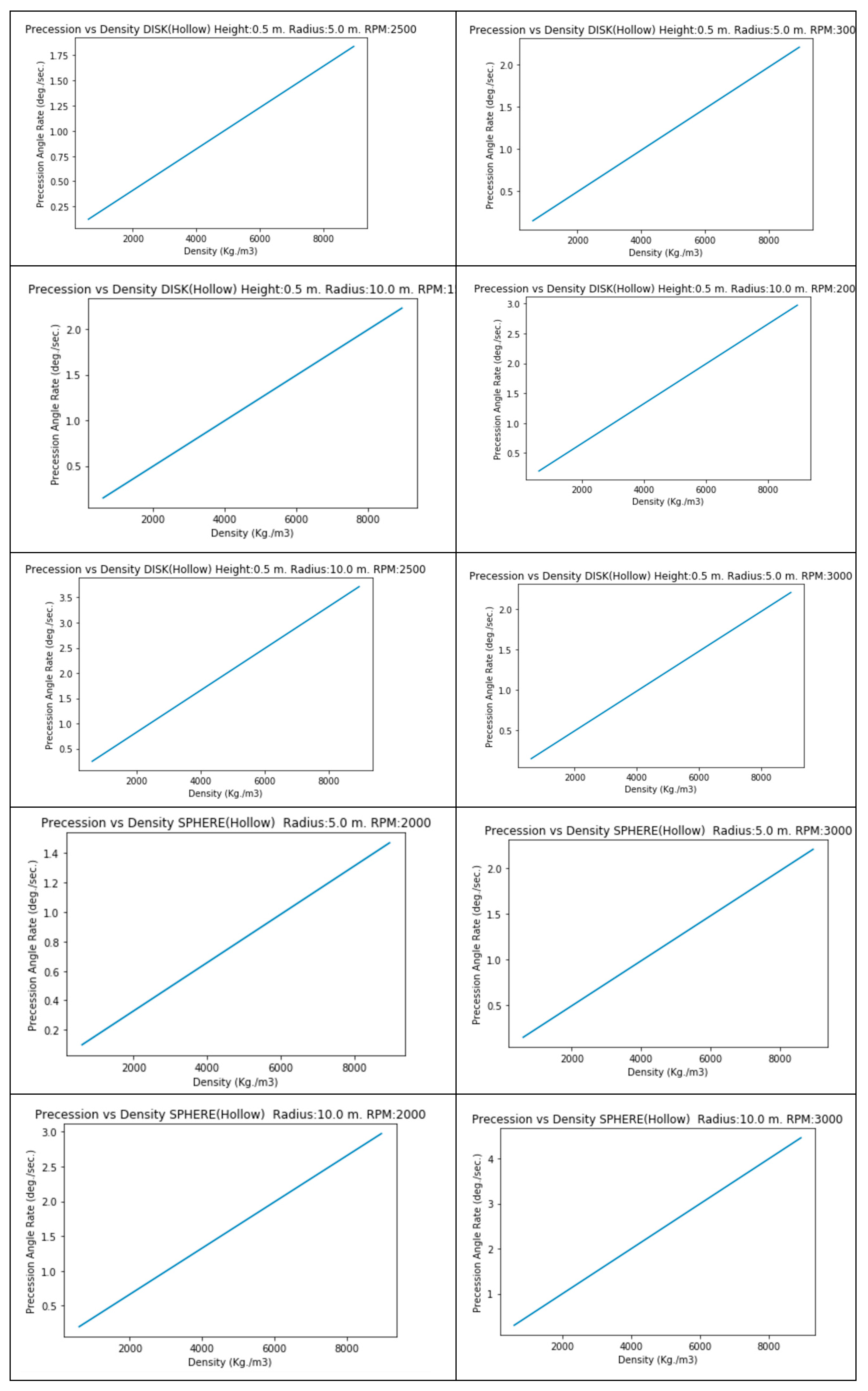
6. Precession Rate vs Material Density
Although relation among precession rate vs density could be easily infered from previous graphs, the following graphs show such relation in detail.
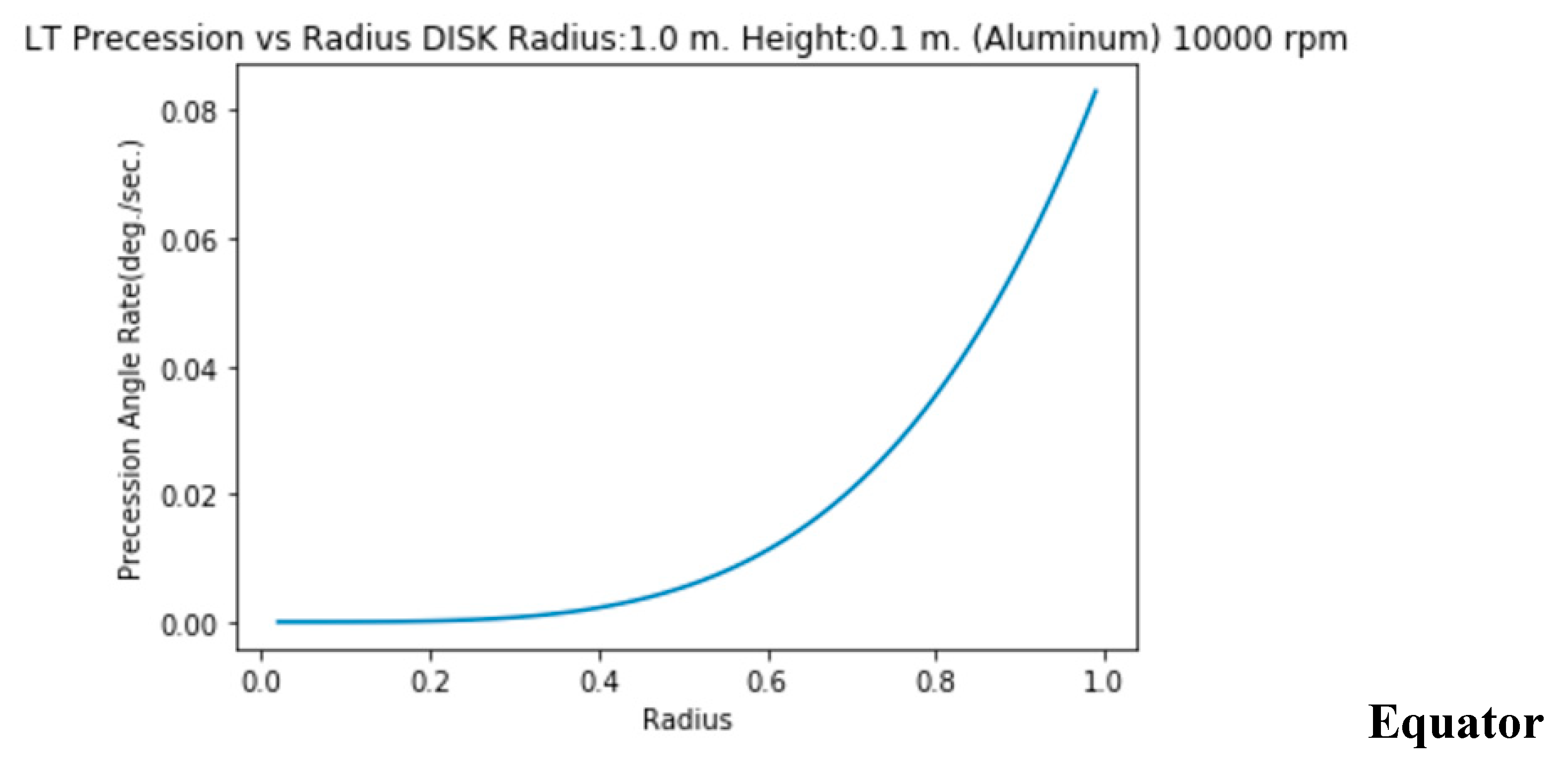
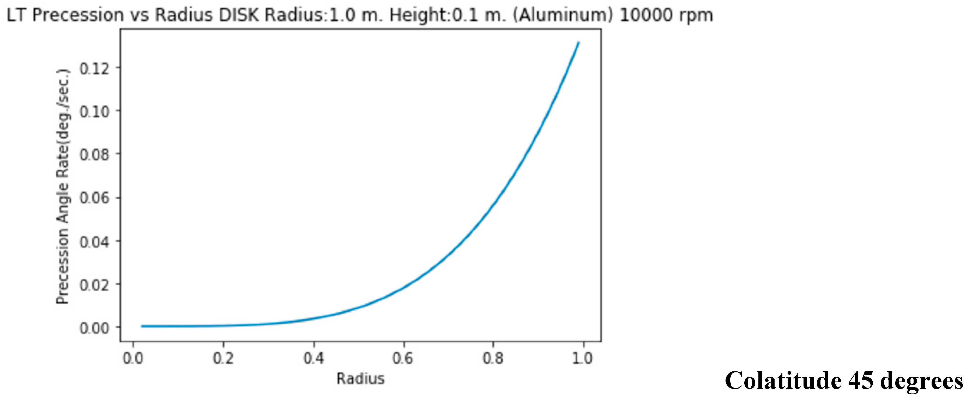
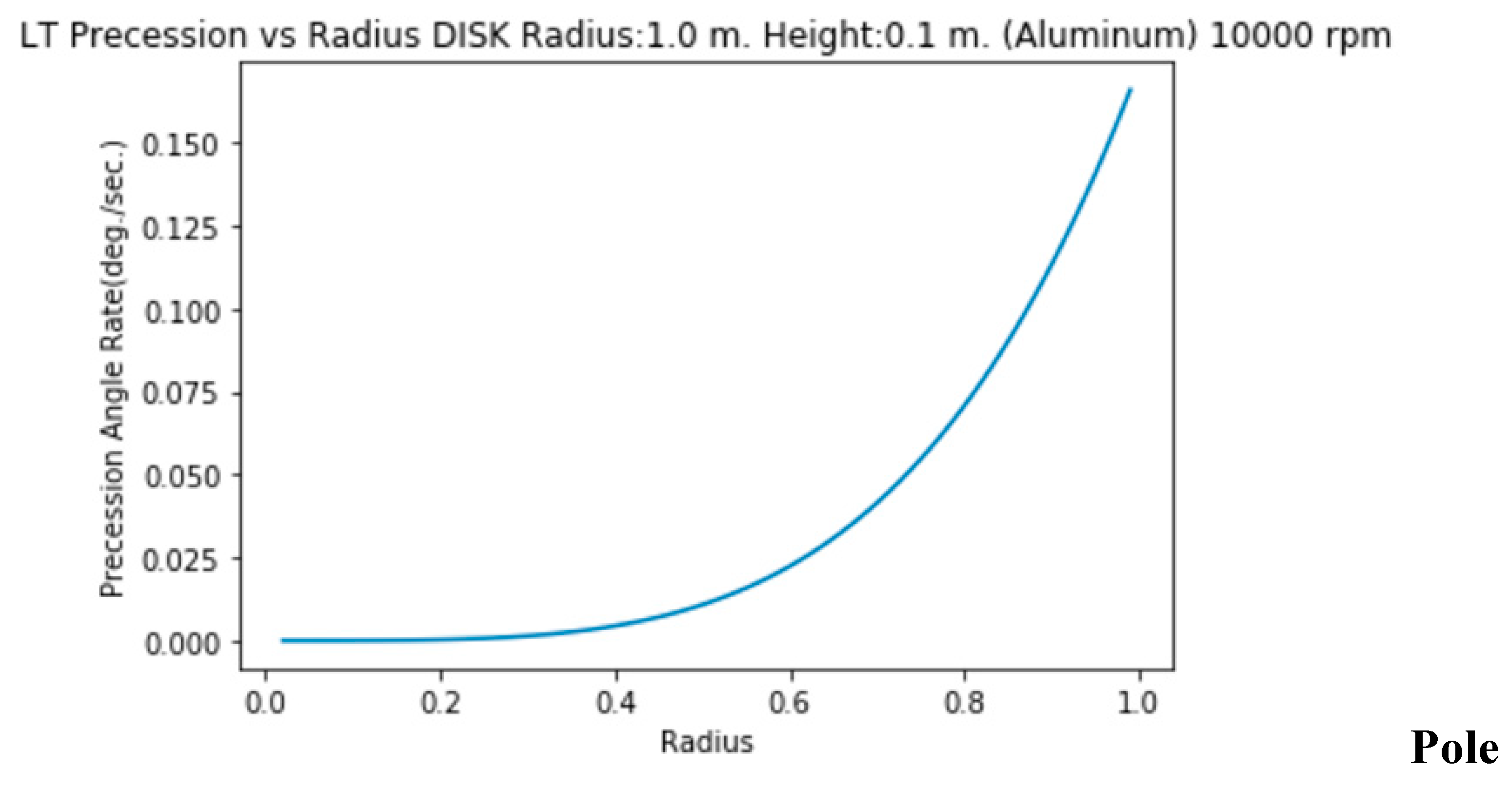
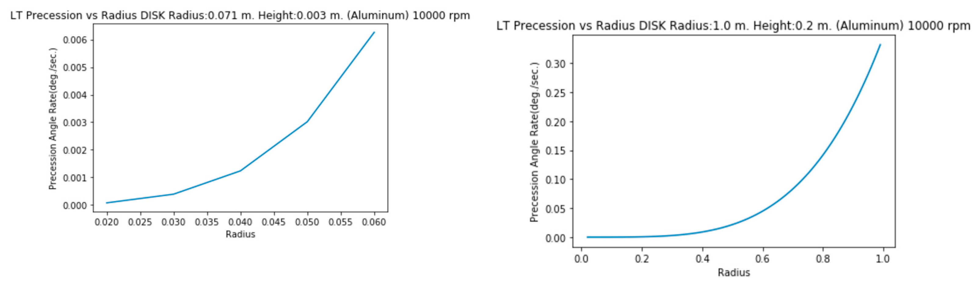
7. Evolution of the Precession Rate Along Radius
- (a)
Spheres
The precession rate increases from radius=0 to radius=R. Here are the graphs along Equator, Pole and for a 45 degrees colatitude.
For very heavy and large objects (e.g. black holes), there’s a lack of continuity for very low values of the radius (0 < R < 3 cm.) which can be identified with the known Kerr singularity [
6]. We’ve found a relevant fact: such singularity has not be found for the small objects of our study.
8. Results Analysis
Relevant conclussion can be reached from the previous results:
- (1)
LT precession rate effect can be very relevant for small objects with high speed of rotation and therefore it should be taken on account to be applied for future space crafts. E.g. For a disk of steel (solid) of 20 m. diameter and 2 m. of height, with a rotation speed of 2000 rpm (33.33 Hz.), that is, 210 rad/s=12032 degrees/sec., the precession rate is 52 degrees/sec., 0,4% of the rotation speed.
- (2)
We can observe that order of magnitude is very relevant and, as consequence, the according impact over the space-time around the object. Therefore a partial zero gravity effect is reached for counter-clockwise rotations and a partial increase of gravity is reached for clockwise rotations.
- (3)
The precession rate for the same rotation speed, diameter and kind of material is larger for solid materials than hollow ones.
- (4)
The precession rate for the same rotation speed and diameter increases with the density of the material.
- (5)
The precesion rate decreases from Poles to Equator.
- (6)
The precession rate increases from the center (0) to radius.
- (7)
The greater the moment of inertia, the greater the precession.
- (8)
For the same radius, the precession rate reached by an sphere is notably greater that the reached by a disk.
- (9)
The results show the values of the module of the LT precession vector, but not the vector components and therefore its direction. In any case, the vector will be oriented towards convexity of space-time for counter-clockwise spins, therefore counteracting the gravitational effect (decreasing the piece weight) and towards the concavity of space-time for clockwise spins (increasing the piece weight).
9. Influence of Precession Rate over Gravity.
I miss some studies about new advanced metrics along last decades. Such lack of research in this field lead us to very limited options when studying environments of a minimum of complexity. Most of current metrics have a lot of limitations and in fact they’re applied only in vacuum. But we have currently very powerful tools (computing, AI) to solve any complex system of differential equations regardless their degree.
It’s a pity that nobody has cared yet about getting metrics involving two or more bodies at least. They could be very useful in every way, including a right space-time interpretation of the great information coming from JWST and Hubble. My view is relying always everything in classic Gravity when we have a theory so powerful (Relativity) is a huge error.
This case is a good example of the previously exposed: we’re not applying Kerr metrics to a black hole or a neutron star. We’re applying it to a simple spinning body but that can’t be considered in vacuum, because it’s subject in this case to Earth Gravity.
Therefore the following study about the influence of the precession rate over Gravity is limited and we must assume some error margin.
We’re going to apply the following limitations:
- (1)
-
Kerr metric is going to be used:

[
11] Taking into account the symbols values as explained previously in (3)
- (2)
The object will have spheric geometry. We’ll apply colatitude ϴ = 0 because of the second term

relationing disappears (=0).
- (3)
We’ll suppose a relationship among dt
2 and Gravity close to linearity just as it’s explained in [
10].
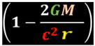
With such suppositions, the time component of the tensor is reduced to
In our case Therefore the time component for a=0 (spinning=0, J=0) reduces the previous expression to Schwarzschild metric:
, that is,
This leads us to that the square of the time difference
simplified to this case among an object spinning around one of its symmetry axis attributable to frame precession and the same object in rest state would be:
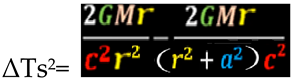
that can be expressed for a more intuitive interpretation as
As can be observed, the Kerr parameter a influences directly over the difference of times.
On the other hand, the object is subject to a gravitational field (Earth in our case).
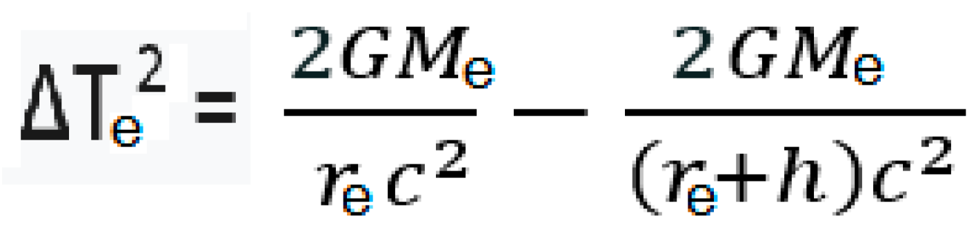
Therefore there’re a difference of times ΔTe (by Gravity) in function of altitude [
10], that can be expressed (being in this case Me the mass of the Earth, re the Earth radius and h the altitude) like:
The difference of times by precession/LT effect (ΔTs) will add to the difference of times by Gravity (ΔTe) if the object is rotating clockwise (increasing the “weight” of the object) and it will substract from ΔTe if the object is rotating counter clockwise (decreasing the “weight” of the object). In such case, equalizing ΔTs= ΔTe and simplifying the resulting equation we could know the value of a needed for reaching an state of Zero Gravity at altitude h:
Mr (1/r2 – 1/(r2+ a2)) = Me (1/re -1/ (re+h)) (10)
From this equation we can calculate easily the value of a for getting a “Zero Gravity” effect (az):
Doing K1=h/(Re*(Re+h)) and K2=M/(Me*r) → az2 = K1 r2 / (K2 - K1 ) (11)
From (11) we can calculate the value of the rotation speed (J=Iω=aMc → ω=aMc/I) for any object of mass M and moment of inertia I for reaching a full Zero Gravity effect and the value of such rotation speed for increasing/decreasing (in function of the direction of rotation) the partial gravity effect over an object.
We also could extrapolate Zero Gravity partial effects from (11) for specific a values.
I insist once more that this is a simplified way. Therefore the results obtained are only an approximation. We should create (and obviously use) more advanced metrics for getting an exact solution.
10. Application to Space-Crafts.
The associated technology will allow to build spacecrafts which take advantage of LT effect.
Combining ZG (Zero Gravity) effect [
10] and LT effect, spacecrafts could increase/decrease the gravity effect (they could even create an antigravity effect or “negative gravity”). LT effect will become more relevant than ZG effect usually at higher altitudes (> 10 Km.) and less relevant than ZG effect to lower altitudes (< 10 Km.), because the influence of the altitude in the case over the LT effect is lower than the influence over ZG effect.
Therefore, we could build spacecrafts which combine ZG+LT effect to get the best of both worlds in order to travel taking advantage of warping the space-time around the spacecraft. In order to difference the ZG effect produced by speed and the ZG effect produced by LT effect, we’re going to call the global ZG effect “Theory of General Zero Gravity” and the specific effect due to speed “Theory of Special Zero Gravity”. We will go into more detail about it later.
From the previous result analysis , we can infer that the more efficient designs for getting the best of both effects for space crafts should be based on solid (or semisolid) spheres and disks. They also predictably would be the simplest to design.
It’s not a goal of this paper to detail the possible designs of the new spacecrafts, but there’s an important fact to take on account: From both points of view (teorethical and practical), ZG and their associated experiments have showed that concavities in space-time produced by Gravity can be not only counteracted until they’re flatten but to the point of creating convexities. Therefore spacecrafts could consist of an spinning body (external rotating semi solid sphere or disk) and an internal hollow operative body. The spinning body would create an anti-gravitatory effect around it which would be enough to counteract its owning gravity + operative body gravity.
COROLLARY.- There is a renewed interest in the old warp drive dream Project.
But there was a huge problem since its formulation long time ago in order to put it to work: There would be needed to find some kind of “antigravitatory material” to create (in our own words, not in theirs) a convexity effect over space-time.
But we have good news for these projects: There’s not need at all to find such material that very likely does not exist. A LT effect can be reached by rotation (counter-clockwise) instead.
In summary, ZG+LT effects could allow theoretically to build a warp drive spacecraft. But there will be other ways to do it as I’ll explain at the end of this paper.
In any case my view is we should learn to walk before to run: spacecrafts based on ZG+LT effect at first, then Warp Drive spacecrafts based on high rotation speeds clockwise and counter-clockwise.
11. Experiments.
Because of the superposition of Zero Gravity (ZG) effect [
10] and Lense Thirring (LT) effect [
2] we should taking on account the following points in order to do a reliable experimentation:
- -
To achieve relevant results, it’s necessary using DC Motors with high speed of rotation (20.000 rpm) for applying the theory to the size and morphology of the kind of pieces that we can handle in a laboratory, even more if we’re talking about a not profesional laboratory. Stability of the kit on the scale plate can be also a problem for larger pieces because of such high rotation speed and the weight of the pieces.
- -
The larger the diameter, the greater the ZG effect. As consequence, it’s more difficult to identify the relevance of the LT effect over the ZG effect.
- -
As commented perviously, we’re not using a profesional laboratory so we have some limitations related with weights and sizes.
Therefore the most suitable pieces for validating the Theory should have the following features: Light weight (low density material), small diameter and shape of disk or similar.
The following piece (Cardboard+PVC) has every of the features that we are demanding:
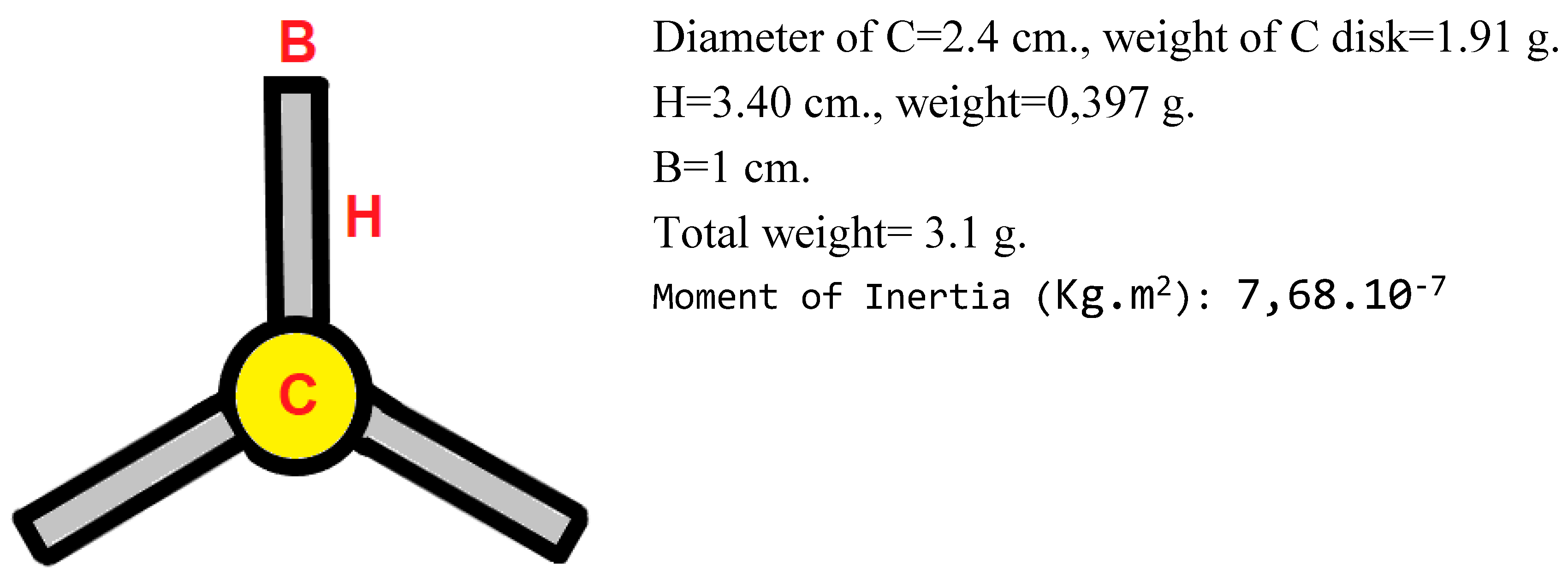
IMPORTANT: Although this piece has the shape of a propeller, **it’s not** a propeller, because the three blades and the central body are in the same plane. Therefore it can’t work as a propeller because it hasn’t any aerodynamic advantage to do it.
This piece has an equivalent radius (the radius for getting the same ZG effect with all the mass concentrated in the periphery) of approx. 2.80 cm.
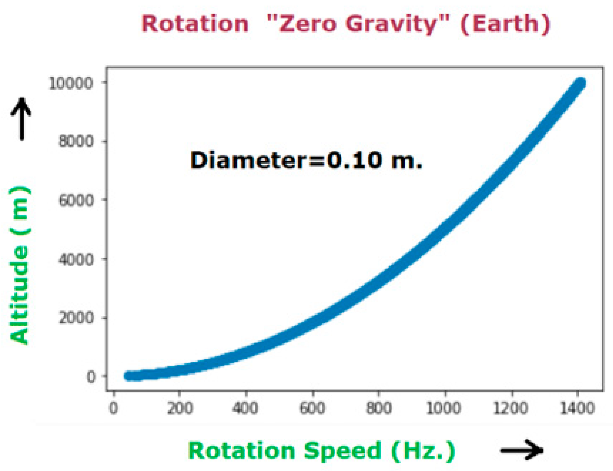
According to ZG Theory, for a diameter of 10 cm., the rotation speed in function of altitude (1000 meters in our case) to reaching full Zero Gravity is approx. 450 Hz.=27000 rpm.
Therefore for an equivalent diameter of 5.60 cm., 27000 x 10/5.60=48214 rpm.
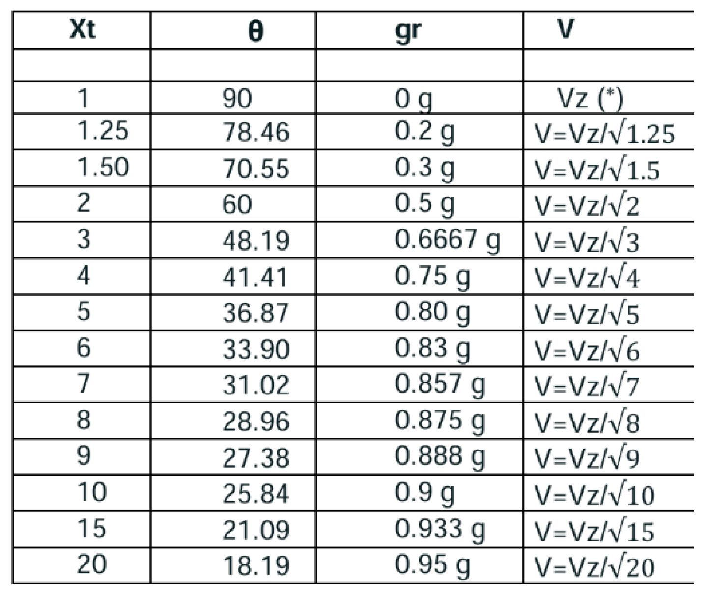
According ZG Theory, for a speed of 20.000/48214=0.41 Vz (4), being Vz the speed of full ZG effect.
Rotation has been applied in both ways: counterclockwise and clockwise. Why?... Because both effects (ZG and LT) are added or substracted depending if the rotation of the piece is counter-clockwise or clockwise.
ZG does not depend of the direction of rotation (creating always a convexity in space-time) but LT yes. LT creates a concavity in space-time (clockwise rotation) or convexity (counterclockwise).
The results obtained by the experiments for two speeds of rotation (20.000 rpm. and 10.000 rpm.) and both directions of rotation, were the following ones:
| Rotation Speed (rpm) |
Weight Difference (Counterclockwise) /g.) |
Weight Difference (Clockwise) (g.) |
| 20.000 |
-0.8 |
-0.5 (I) |
| 10.000 |
-0.5 |
-0.2 (II) |
We can reflect the results got in (I) in the simple equation system:
ZG+LT=-0.8 ZG-LT=-0.5 → ZG=-0.65g LT=-0.15g
Therefore the ZG effect reached at 20.000 rpm is 0.65g/3.10g=0,21 M being the M the mass (3.10 g.) of the piece.
According ZG Theory [
10] again, for reaching a 0,21 M of partial ZG, the rotation speed should be approx. 0,45 Vz.(5)
We can observe that (5) is very close to (4). The little difference (0,04 Vz) can be attributed to a logical error margin of the experiment.
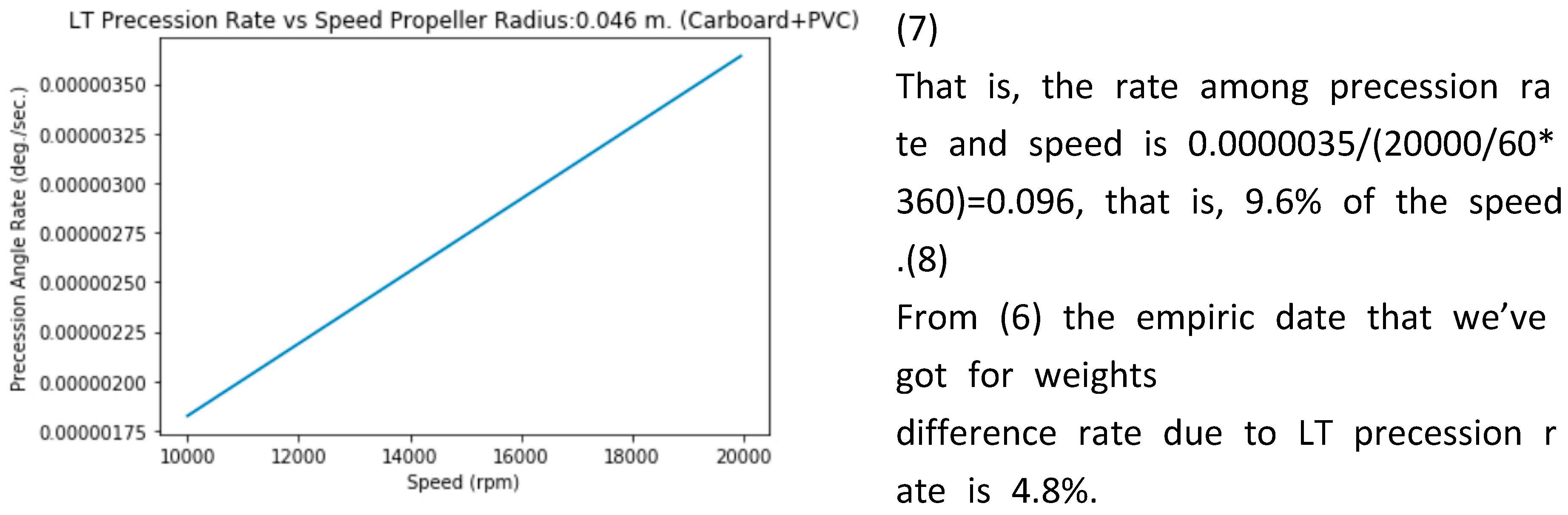
As for the LT effect, we’ve reached a 0.15g/3.10g=4.8% of the weight difference due to LT. It’s substracted for counter clockwise rotation and added for clockwise rotation. (6) This is the reason why different weights were obtained in the experiment depending on the direction of rotation.
The moment of inertia of the piece (simple calculus) is Ip=7.68e-07 Kg.m2
Therefore, we can calculate the radius of the equivalent disk, that is, a disk with the same moment of inertia (Ieq=Ip.
R=√Ieq*2/M=2.22 cm.
To do: deducing (by creating a new advanced metrics) the difference of gravity and comparing with the empirical result. (6)
12. Future Associated Research.
The exact influence of the LT effect over rotating objects subjected to a gravity field in terms of gravity (not only precession) would need of a deeper study based on a new metric that currently does not exist.
Although Kerr metric could be used as a first approximation (just as we did it previously to get the precession rate), we must take on account that we’re not in a vacuum solution: our object/space craft is subject to the gravity of another (or others) objects. This greatly complicates Einstein field equations. In fact I think that there’s currently a lack of advanced metrics for Einstein field equations in Physics although we’ve got a lot of resources to solve them (computing, AI). Resources that unfortunately had not previous physicists some decades ago.
In any case, the research should be also supported for a relevant number of experiments with very different kind of shapes, materials and rotation speeds.
References
- Lense-Thirring precession, Wikipedia, https://en.wikipedia.org/wiki/Lense%E2%80%93Thirring_precession.
- Lense, J.; Thirring, H. Phys. Z. 1918, 19, 156–163.
- Hartle, J. B. Gravity:An introduction to Einstein’s General relativity; Pearson, 2009. [Google Scholar]
- Kerr, R. P. Phys. Rev. Lett. 1963, 11, 237–238. [CrossRef]
- Schwarzschild, K. Uber das Gravitationsfeld einer Kugel aus inkom pressibler Flussigkeit nach der Einsteinschen Theorie. Sitzungsberichte der K¨oniglich Preussischen Akademie der Wissenschaften 1916, I, 424–434. [Google Scholar]
- Roy Kerr and Wilson, W. B., “Singularities in the Kerr-Schild metrics”, General Relativity and Gravitation– GR8 1977, proceedings of the 8th International Conference on General Relativity and Gravitation, held August 7-12, 1977, in Waterloo, Ontario, Canada. 1977, p. 378.
- Lense-Thirring Precession in Strong Gravitational Fields, Chandrachur Chakraborty, 28th Texas Symposium on Relativistic Astrophysics Geneva, Switzerland– December 13-18, 2015.
- Strong gravity Lense-Thirring Precession in Kerr and Kerr-Taub-NUT spacetimes, Chandrachur Chakraborty [1304.6936v2] Strong gravity Lense-Thirring Precession in Kerr and Kerr-Taub-NUT spacetimes (2014).
- Frame dragging effect in Strong Gravity Regime, Chandrachur Chakraborty [1603.04303v1] Frame-dragging Effect in Strong Gravity Regime (2016).
- Zero Gravity Theory, F. Javier Cuesta Gutierrez, Amazon ISBN 979-8321956175 (January 2024).
- Espín del Agujero Negro en rotación tipo Kerr, David Escors, Fisica Moderna (YouTube), https://www.youtube.com/watch?v=Ltz--VuRDug.
|
Disclaimer/Publisher’s Note: The statements, opinions and data contained in all publications are solely those of the individual author(s) and contributor(s) and not of MDPI and/or the editor(s). MDPI and/or the editor(s) disclaim responsibility for any injury to people or property resulting from any ideas, methods, instructions or products referred to in the content. |
© 2024 by the authors. Licensee MDPI, Basel, Switzerland. This article is an open access article distributed under the terms and conditions of the Creative Commons Attribution (CC BY) license (http://creativecommons.org/licenses/by/4.0/).