1. Introduction
With the continuous improvement of intelligent transportation, autonomous driving, and vehicle control system technology, the Vehicle Servo System (VSS) platform is increasingly vital in intelligent driving, automatic parking, and robot control [
1]. As a type of VSS, the Electro-Mechanical Brake (EMB) system directly drives the brake caliper through an electric motor to control the braking force. It has the advantages of fast response speed, compact structure, and easy maintenance. However, EMB faces multiple challenges in practical applications, such as external disturbances, changes in system parameters, and complex environmental factors. Traditional methods such as PID control and robust control can to some extent guarantee the basic performance, but they often struggle to cater for the requirements of real-time and accuracy when facing complex operating conditions with large-scale nonlinearity, time-varying disturbances, and high dynamic characteristics [
2]. Active Disturbance Rejection Control (ADRC), as a novel control method, has received widespread attention for its ability to directly handle system disturbances without the need for an accurate model. Although ADRC can effectively suppress external disturbances under certain conditions, its control accuracy and robustness are still limited by factors such as parameter selection and disturbance estimation accuracy [
3]. By utilizing Artificial Intelligence (AI) algorithms for system modeling, parameter optimization, and disturbance estimation, the adaptability and accuracy of the system can be effectively improved. Particle Swarm Optimization (PSO), as a type of AI algorithm, simulates the behavior of particle swarm in nature and utilizes the collaboration and information sharing among individuals in the group to find the optima [
4].
The EMB system can be combined with different control methods and algorithms to effectively improve the stability, precision, and reliability of the system. WANG et al. combined EMB actuator's full braking and three loop PID control to ensure the heavy braking load of autonomous vehicles, avoiding uneven braking force and achieving tracking. The prediction error of this method was less than 10% [
5]. Song et al. utilized two Electronic Control Units (ECUs) and a dual winding motor to achieve tooth modulation effect for vehicle redundancy. This method had practicality [
6]. Zhou et al. introduced fuzzy regenerative braking control into the EMB system model for the regenerative braking of electric vehicles, and improved it by combining it with the NSGA-II algorithm. This method had good stability [
7]. Xu et al. developed a switching Extended State Observer (ESO) considering equivalent gain for fast force estimation to improve the performance of EMB. This method had good accuracy [
8]. Zhao et al. constructed a nonlinear mathematical model of the EMB system and an enhanced ESO to improve sensor reliability to enhance its performance, which was effective [
9].
Some researchers have significantly improved the performance of the ADRC system by combining advanced control theory and technology to optimize it. Zhao et al. optimized ADRC by combining brake dead time compensation and adaptive LuGre friction model to improve the accuracy and speed of pressure response execution, which is feasible [
10]. Jin et al. proposed a second-order linear ADRC controller by combining integrator chain and tuning control to improve controller stability and achieve the expected frequency response. This controller had robustness [
11]. Liu et al. proposed an ADRC cascade active suppression control strategy based on radial basis function neural networks for the high-voltage control problem of the system, to avoid coupling interference. This method had good anti-interference performance [
12]. Safiullah et al. proposed a second-order active ADRC to reduce error and estimation performance uncertainty to simultaneously control multiple modules of the system, which performed well [
13]. Madonski et al. designed a structure for linear ADRC by combining output and error to build modules to enhance the efficient control of ADRC. This design had applicability [
14].
In summary, both EMB system and ADRC have achieved good results in their respective application fields. However, facing complex working conditions, the system still has the problem of low robustness and anti-interference ability to external disturbances. Therefore, this study optimizes the EMB system through ADRC and PSO algorithms to improve system performance. At the same time, a control method that adapts to complex working conditions in conjunction with the Anti-lock Braking System (ABS) of the vehicle is designed to improve the real-time performance and stability of the system. This study aims to further improve the control performance of the VSS platform, enhance the system's robustness and anti-interference ability to external disturbances.
2. Methods and Materials
This study first builds a new EMB actuator in the EMB system and then introduces the PSO algorithm to achieve ADRC clamping force control optimization. Meanwhile, a joint control method for steering and braking is proposed to cope with vehicle control in different scenarios.
2.1. EMB Actuator Modeling
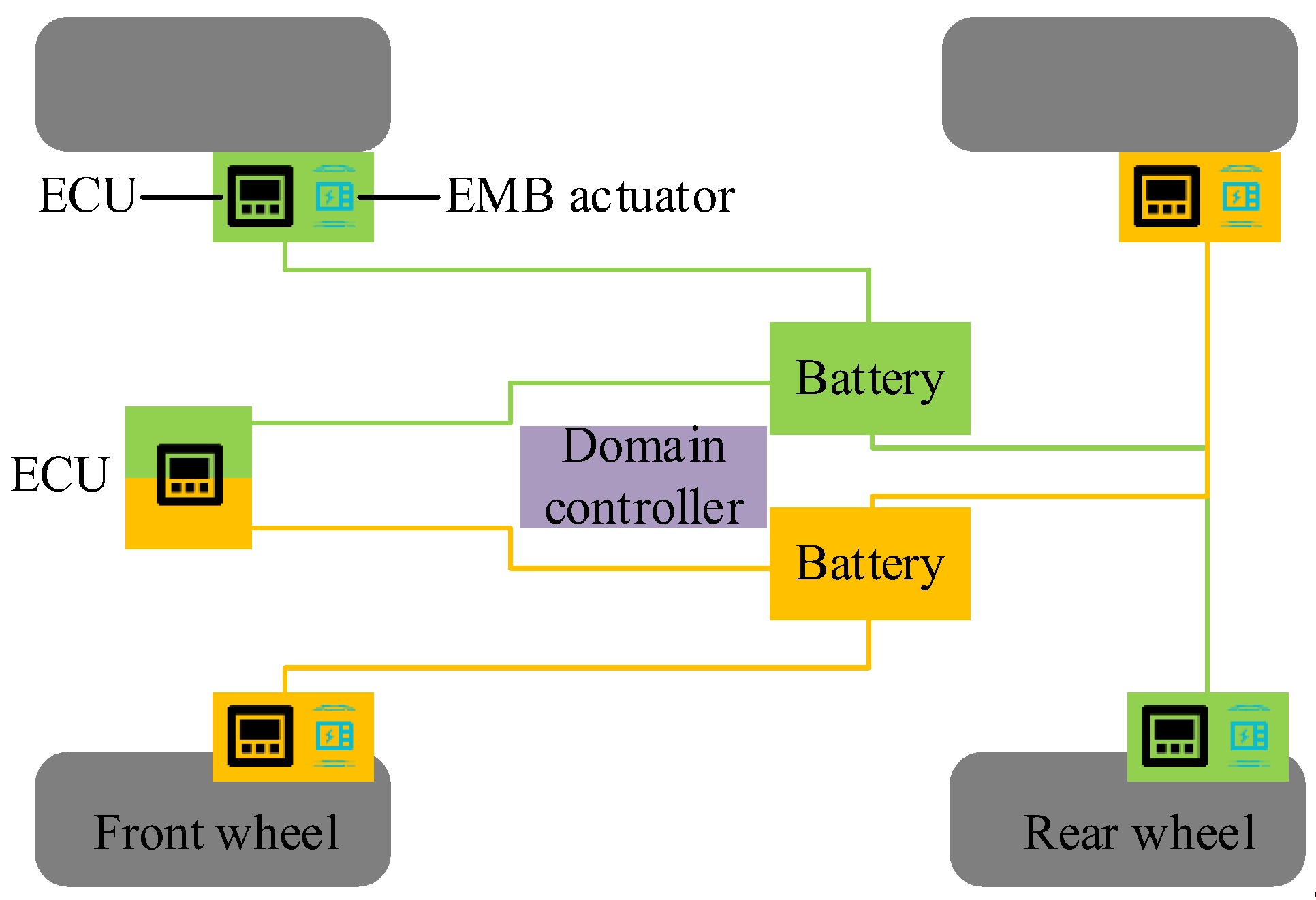
Due to the strong coupling, time-varying and other nonlinear characteristics of EMB systems, to ensure the real-time and stability of the system, this study designs a prototype EMB actuator and proposes relevant simulation models. The EMB system structure and working mechanism are shown in
Figure 1.
In
Figure 1, the EMB system mainly consists of EMB controller, EMB actuator, wheel brake module, ECU, and power supply. The EMB actuator consists of a driving motor, a deceleration and torque increasing device, and a motion conversion mechanism. These components work together to precisely control the rotation of the motor through the ECU, converting rotational motion into translational motion and driving the brake disc pad to generate braking force. The EMB controller is the core part of the EMB system, responsible for receiving signals, determining the driver's intention, and outputting brake commands to the brake controller [
15]. The motion conversion mechanism is responsible for converting rotational motion into translational motion, driving the brake disc pad to generate braking force. The wheel brake module consists of brake actuators, brake controllers, mechanical transmission mechanisms, and sensors. The brake pedal module includes brake pedals, pedal simulators, displacement/pressure sensors, etc. The communication network coordinates the entire braking system and is responsible for sending various signals to designated areas. The power supply provides energy for the entire braking system. These components work together to provide fast and precise braking response, and support advanced vehicle control functions and energy recovery [
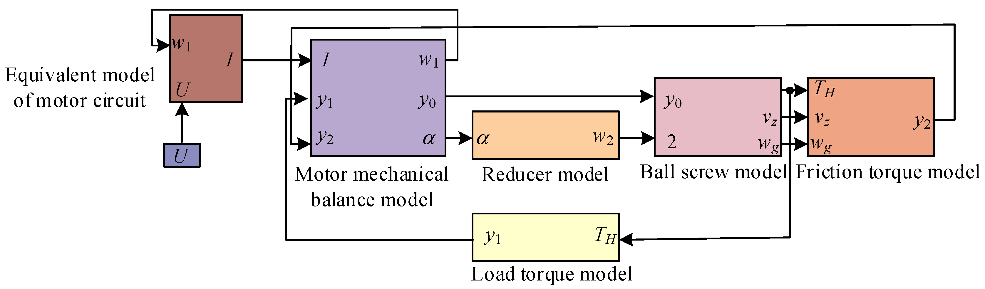
16]. The composition of the EMB actuator model constructed is shown in
Figure 2.
In
Figure 2, the model of the actuator includes the equivalent model of the motor circuit, the mechanical balance model of the motor, the reducer model, the ball screw model, the friction torque model, and the load torque model. The equivalent model of the motor circuit outputs the armature current
and motor angular velocity
to the mechanical balance model of the motor. The relevant motor angle and reducer angle in the reducer model are
and
. The electromagnetic torque
, load torque
, and friction torque
of the motor are respectively linked to the ball screw model, load torque model, and friction torque model. The relevant formula for the voltage
equation of a motor rotor with a resistance of
is shown in equation (1) [
17].
In equation (1),
represents the ability of the armature winding to store and release magnetic field energy during the operation of the motor.
is the value of the back electromotive force coefficient.
is the electromagnetic force generated by a unit current.
is the electromotive force generated in a closed circuit.
is the inertia magnitude of the motor rotation. In the EMB system, the clamping force
is converted through the ball screw and friction torque model, and ultimately acts on the braking system [
18]. When the torque driven by the motor acts on the nut, the nut will move along the ball screw, causing displacement of the nut components in the system. The relationship between the
generated by EMB and the nut displacement
is shown in equation (2).
Friction torque is a very important part of the braking system, which determines the contact force between the brake disc and the pad. The
of the brake pad is affected by the reducer, generating a braking torque
. Assuming that both sides of the brake disc have consistent friction coefficients, the formula for the frictional relationship between the brake pad and the brake disc is shown in equation (3).
In equation (3),
is the friction coefficient, and the larger the value, the stronger the braking effect and the greater the amount of
.
is the radius of the brake disc that directly affects the magnitude of the friction torque. The larger the
, the greater the
generated under the same friction force. The relationship between clamping force
and load torque
is shown in equation (4).
In equation (4), is the reduction ratio of the reducer, and is the lead of the ball screw.
2.2. Optimization Method for ADRC Clamping Force Control Introducing PSO Algorithm
The nonlinear and time-varying characteristics of EMB systems make it difficult for traditional control methods to achieve precise control, especially in situations where high real-time and stability requirements are needed. ADRC can estimate and compensate for internal and external disturbances in real-time, improving the robustness and response velocity. Due to the interference and multiple uncertain factors of EMB actuators, the system is complex and difficult to accurately describe. Therefore, this study approximates the EMB actuator as a second-order nonlinear system, and the state equation of this system is shown in equation (5).
In equation (5),
and
are the state variables.
is the gain coefficient.
is the control quantity.
is a nonlinear function.
is the system disturbance.
is the output of the system. ADRC has fast response time and high tracking accuracy. Applying it to EMB systems can solve the problems of time-delay response and precise control of actuators [
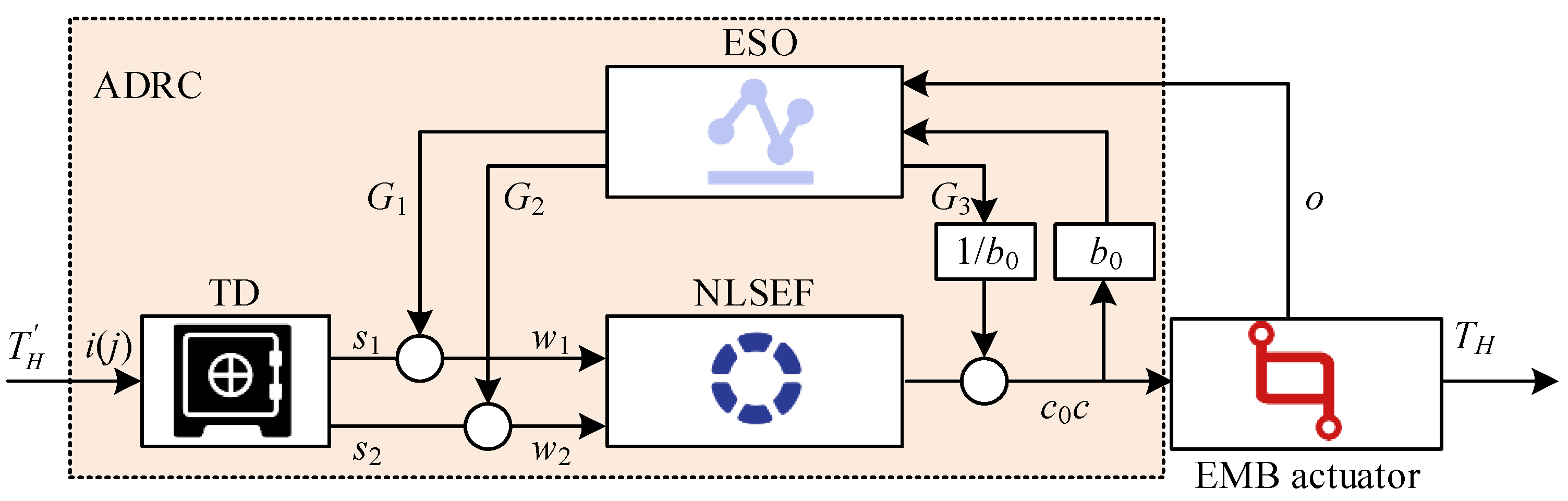
19]. The ADRC structure diagram is shown in
Figure 3.
In
Figure 3, the ADRC controller includes three components: a Tracking Differentiator (TD), Nonlinear State Error Feedback (NLSEF), and ESO. Target signal
is input, resulting in state variables
and
. The specific meanings of the two refer to the tracking value of
and its differential estimation value. The system output
is the actual clamping force.
and
are the system control variables before and after disturbance compensation.
represents the actual driving current. TD can address extracting continuous and differential signals from measurement signals that are discontinuous or contain random noise. Based on the differential output and the fastest synthesis function
, the transition process of the closed-loop system can be arranged [
20]. The form of TD discrete relationship is shown in equation (6).
In equation (6),
and
are the velocity factor and filtering factor.
is the integration step size.
and
are both nonlinear factors. NLSEF performs control and disturbance compensation based on the errors
and
between the given signal and its derivative obtained from TD, and the system output and its derivative observed by the state observer. The nonlinear control method is established by the nonlinear function
or the
, and the relevant calculations are shown in equation (7) [
21].
In equation (7), the estimated value
of
. The estimated differential value is
.
and
are proportional coefficients and differential coefficients.
and
determine the size of the linear interval of the nonlinear function, with the value
. The calculation of the compensation control rate for the estimated Total Disturbance (TDis)
is shown in equation (8).
ESO expands the disturbance effect that affects the output of the controlled object into new state variables, and observes the expanded TDis signal through a special feedback mechanism input. The output construction TDis
is a state variable. The 2nd-order system has an extended observer that reaches the 3rd-order and incorporates the state of TDis. The TDis includes internal disturbances and external high-frequency noise interference, and the relevant calculations are shown in equation (9) [
22].
In equation (9),
,
, and
are all control parameters.
is the error signal.
is the correction factor.
is the control parameter of the nonlinear function,
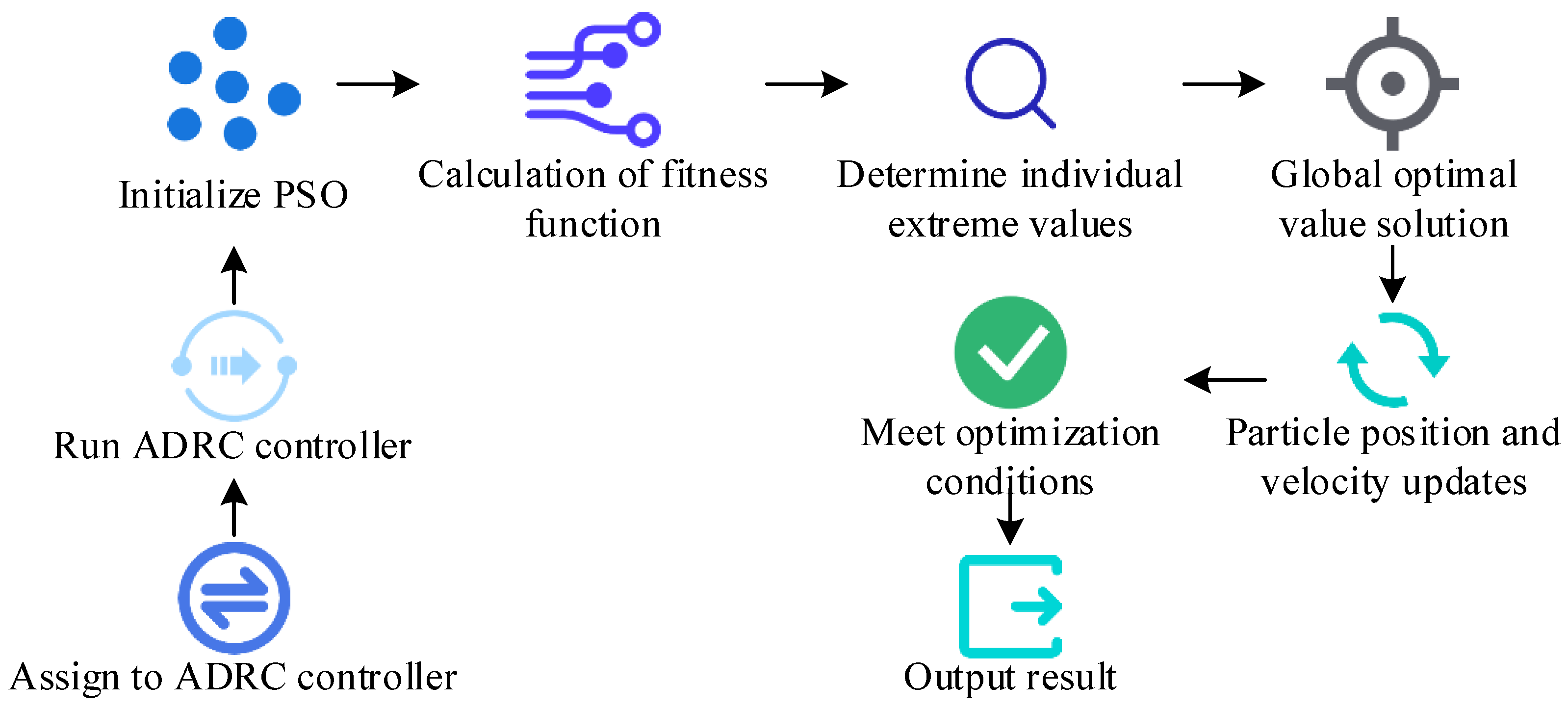
. Due to the time-consuming and unsatisfactory results of conventional methods for determining parameters, to improve efficiency, this study separately optimizes the parameters of the three components of the ADRC controller. The PSO is suitable for nonlinear and multi-objective optimization problems and can be used to optimize the parameters of ADRC controllers. This study introduces PSO to improve optimization efficiency. The process of PSO participating in optimizing ADRC controller is shown in
Figure 4.
In
Figure 4, the first step is to initialize the PSO. Before this process, it is necessary to assign a value to the ADRC controller and run it. In the optimization process, it is necessary to evaluate the fitness function of each particle to determine whether its position is close to the optimal solution. PSO searches the solution space by continuously updating the position and velocity of particles, gradually approaching the global optimal solution. The relevant formulas for updating the particle velocity
and particle position of the next iteration
are shown in equation (10).
In equation (10),
is the particle of iteration
.
is the optimal position obtained by
iteration.
is the latest location.
and
are learning factors.
and
are both random numbers,
,
. The fitness function of PSO is based on the Integral of Time multiplied by the Absolute Error (ITAE). Optimization objective
is the clamping force error and response time, calculated using equation (11).
In equation (11), is the clamping force error value, and is the response coefficient. After the velocity and position of the particles are updated, the system will determine whether the optimization conditions are met. If the conditions are met, the optimal result will be output.
2.3. Joint Control Method for Steering and Braking
During emergency braking, relying solely on the ABS system may not fully guarantee the stability of the vehicle under complex road conditions. By incorporating an autonomous steering system, stability can be further enhanced by adjusting the steering angle of the vehicle's front wheels. To achieve more comprehensive vehicle dynamic control, this study combines EMB system, ABS, and autonomous steering system. The EMB system can be seamlessly integrated with ABS, providing more comprehensive vehicle dynamic control [
23]. Considering the emergency braking of vehicles in actual road conditions and the special time lag of EMB systems, a joint controller has been developed. The dynamic response of vehicles varies under various road adhesion conditions. The joint control method can adjust the control strategy based on actual road conditions to ensure braking effectiveness and vehicle stability under various conditions. The joint control structure in the VSS platform is shown in
Figure 5.
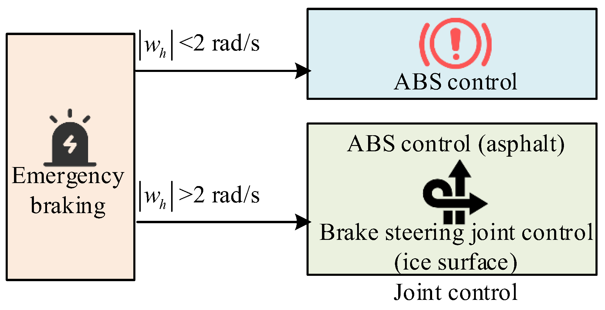
In
Figure 5, when
<2rad/s, the vehicle tires are mainly controlled by ABS. At
>2rad/s, control strategies are selected based on different road adhesion conditions. For low grip road surfaces such as snow and ice, the side tires are controlled by ABS. For high grip road surfaces, the side tires and front wheels are controlled by a combined steering and braking control system. By utilizing the fast response characteristics of the EMB system, combined with the stable control of ABS and the flexible adjustment of the autonomous steering system, more efficient braking control has been achieved. The derivative of
is
, and the derivative
equation of the wheel slip ratio
is shown in equation (12) [
24].
In equation (12),
is the average time for EMB actuators to respond to control signals under normal operating conditions.
is the change in actuator response time caused by external disturbances or complex physical processes in the system.
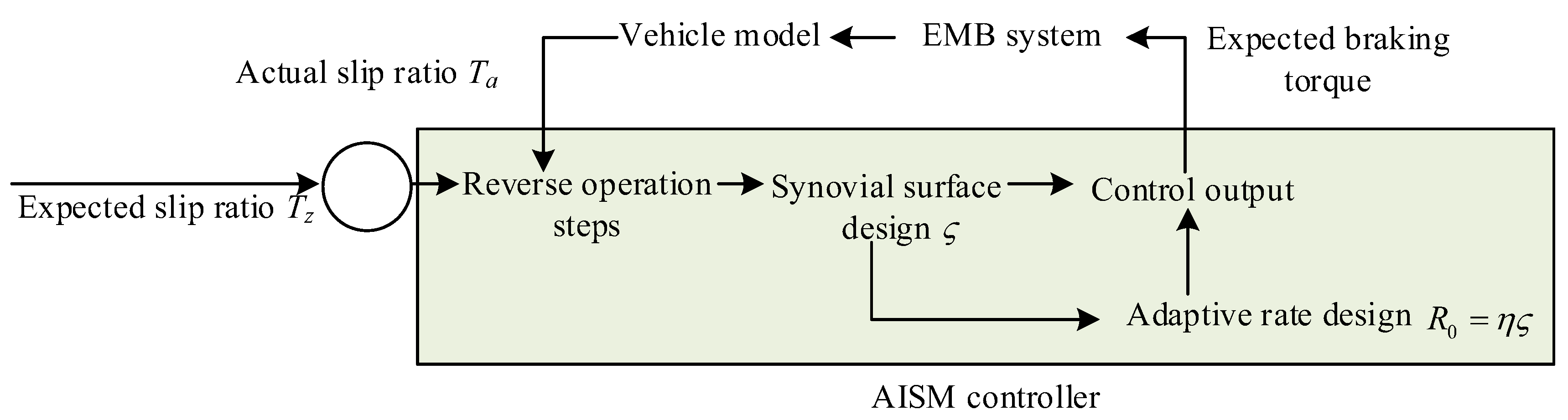
is the system prediction equation. EMB actuators have response lag, which common ABS control methods cannot effectively handle, thereby affecting control accuracy and response speed. Meanwhile, the ABS system needs to maintain the desired slip ratio to ensure effective deceleration and stability of the vehicle during braking. However, traditional ABS systems have shortcomings when facing time delay, uncertainty, and complex dynamic environments. To address these issues, Adaptive Inverse Sliding Mode (AISM) control has been introduced into the ABS system to optimize its performance. AISM control is an advanced control method that fuses adaptive control and sliding mode control. The adaptability enables this control method to adjust control parameters in real-time according to environmental changes. Reverse sliding mode improves the robustness of the system to uncertainties and disturbances. AISM can self-adjust control parameters built on the dynamic characteristics, enabling the control system to maintain high efficiency and stability even in the face of different road conditions and dynamic environments. The control framework for optimizing the ABS system is shown in
Figure 6.
In
Figure 6, the system first receives the expected slip ratio to ensure that the vehicle can effectively decelerate without losing stability during braking. The controller performs reverse operation steps to calculate the required control inputs to achieve the desired slip ratio. Then, sliding mode surface
is designed to determine the system state deviation, and the control input is adjusted through sliding mode control law to make the system state approach the
. The adaptive rate is
, and
is a normal number, which enables the controller to self-adjust according to the dynamic characteristics, thereby improving control accuracy and robustness. The controller calculates the expected braking torque and inputs it into the EMB system. The EMB system receives the expected braking torque
and outputs the actual braking torque
. The EMB system has fast response capability and can accurately apply braking torque. The actual braking torque is applied to the vehicle model. The vehicle model outputs the actual slip rate. The actual slip rate is compared with the expected slip rate, the difference is fed back to the AISM controller, and the reverse sliding film control law is adjusted to further optimize the braking effect [
25]. The inverse synovial control law is the core part of this control framework. The expression for the actual control input
is shown in equation (13).
In equation (13), both
and
are normal numbers.
and
are the actual control quantity and the expected control quantity.
is the aggregated uncertainty caused by time delay. By selecting appropriate weights, it can be ensured that the control system is asymptotically stable under Lyapunov stability theory, that is, the system state can gradually approach the expected state [
26]. The expression for the weight diagonal matrix
is shown in equation (14).
In equation (14), appropriate
,
, and
are selected to ensure that the matrix always has positive values. For high adhesion road surfaces, model predictive control method is used for joint control, setting control objectives for vehicle stability and speed, and considering constraints on EMB input and its rate of change. The framework of the joint control model is displayed in
Figure 7.
In
Figure 7, the vehicle model sets control objectives for stability and speed, as well as constraints on EMB input and its rate of change, based on the prediction equation and reference trajectory under the influence of vehicle parameters. The objective function is obtained under control objectives and constraints, and error feedback is performed [
27]. After feedback to the autonomous steering system and EMB system, the parameters obtained by both are output to the model. To simplify the controller design, this study sets the time delay of EMB braking and steering braking as fixed values. The joint control system dynamically adjusts the braking and steering control strategies built on the current road conditions, vehicle status, and target requirements to achieve more efficient braking effects [
28,
29]. The cost function
at time
measures the quality of joint control, as given by equation (15).
In equation (15), is the importance of different parameters. is a first-order exponential function reference vector. This study proposes a joint control method for complex operating conditions by jointly optimizing EMB and ABS systems. This can optimize braking performance and enhance the robustness of the vehicle to external disturbances while ensuring vehicle stability, thereby improving the overall control performance of the VSS platform.
3. Results
This study first completes the test results of EMB control on the testing platform, and then evaluates the optimized ABS control method in different scenarios. For the joint control method, this study selects different road surface types for practical application analysis.
3.1. EMB Control Test Results
This study selects a semi-physical hardware in the loop testing platform, Windows 10 operating system, and 32GB of memory. The hardware configuration includes EMB prototype, Hardware Control Unit (HCU) upper computer, HCU, and real-time simulator. The software configuration requires NI VeriStand testing software and Matlab/Simulink models [
30]. After PSO optimization parameters,
Table 1 shows the parameter settings for ADRC.
To verify the performance of the developed EMB actuator in practical applications, this study evaluates its performance under real conditions by comparing the changes in current, speed, and clamping force between the developed EMB actuator and actual signals. The changes in current, speed, and clamping force of the actual signal and the developed EMB actuator at the same time are shown in
Figure 8.
In
Figure 8 (a), within 5 seconds, the current changes of the developed EMB actuator are basically consistent with the actual signal. The developed EMB actuator can track actual signals well in terms of current changes, with high response speed and control accuracy. The current change curve first rises and then remains unchanged, finally stabilizing at 2.45A. After reaching the preset state, the system can maintain stable current output, and its current response characteristics meet the design requirements. In
Figure 8 (b), the current variation of the developed EMB actuator is basically consistent with the actual signal. The rotational speed gradually decreased from 26 rad/s to 0 and completely stopped at 1.9 seconds, indicating good fast response capability of the system. The two are highly consistent in terms of speed variation, indicating good dynamic response and deceleration performance. In
Figure 8 (c), the clamping force variation trend between the developed EMB actuator and the actual signal first increases and then remains stable. The actual signal and the clamping force of the developed EMB actuator ultimately stabilize at 2.11×10
4N and 2.16×10
4N. Although there is a slight difference in the final clamping force value, the overall trend of change is very close to the final stable value, indicating that the developed EMB actuator can track the actual signal well. The EMB actuator developed has high accuracy and reliability in clamping force control.
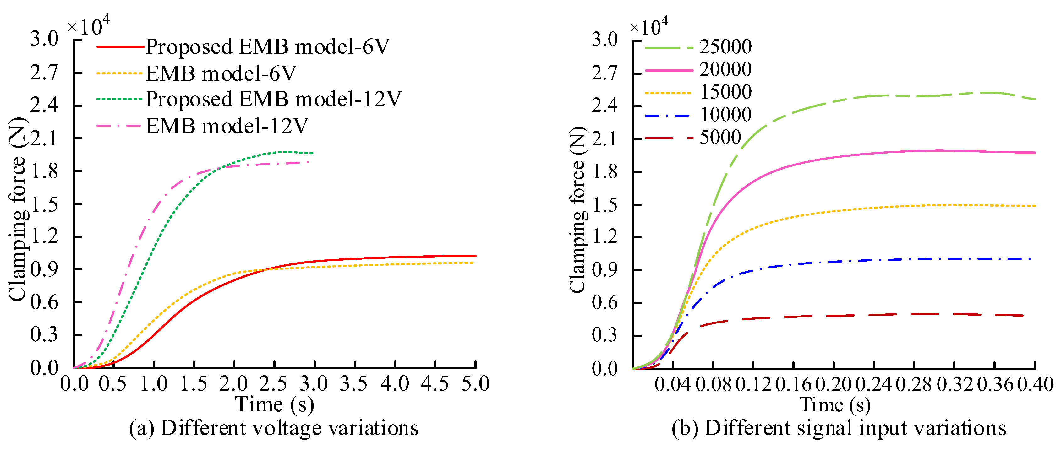
To verify the consistency between the EMB model and the actual model in terms of clamping force response characteristics, the same 6V and 12V voltages are sent to both models, and the changes in clamping force over time are recorded. Meanwhile, the control performance of ADRC on clamping force is compared under different clamping forces. The clamping force variation curve obtained is shown in
Figure 9.
In
Figure 9 (a), there is a certain gap between the proposed model and the actual physical model at 6V and 12V voltages. However, the clamping force response characteristics of the two have good similarity. The research model can better reflect the dynamic behavior of the actual system and meet the requirements of system development. In
Figure 9 (b), the ADRC controller is able to quickly and stably track the target clamping force in the clamping force range of 5,000N to 25,000N during testing. Its strong adaptability to different expected clamping forces. The ADRC controller can achieve fast and stable tracking response under different clamping force conditions, effectively dealing with disturbances and uncertainties in the system.
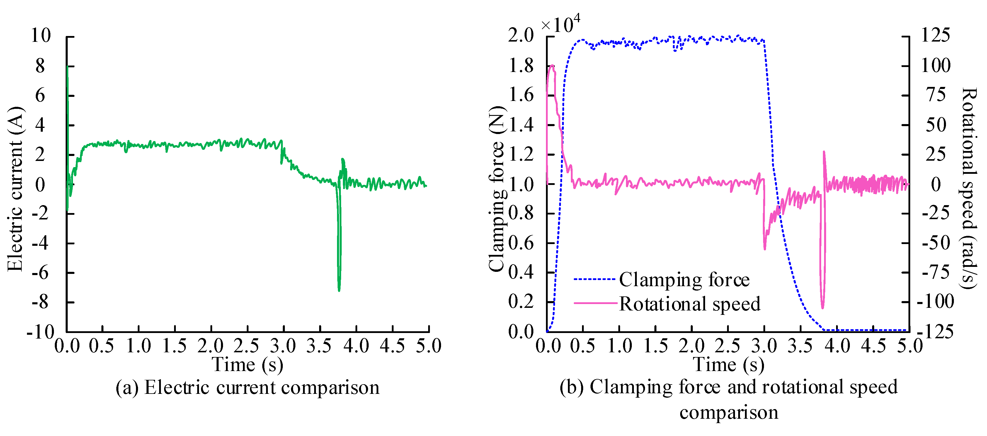
To verify the influence of EMB on various parameters at different stages, it is expected that the clamping force will be set as a two-stage step change. The first paragraph shows a step change in clamping force to 20kN at 0s. The second paragraph states that at 3 seconds, the clamping force will step back to 0. During the simulation of rapid changes in brake clamping force, the EMB motor speed, clamping force, and current response are shown in
Figure 10.
In
Figure 10 (a), the current drops rapidly at 0s, then gradually increases within 0.2s, and finally stabilizes at 2.4A at 3.0s, with a slow decrease in current from 3.0s to 5.0s. This process represents the sensitivity of the EMB control system response, achieving the set clamping force target in a short period of time. At the same time, it can maintain the required current value for the target clamping force, ensuring stable operation of the system. In
Figure 10 (b), the clamping force rapidly increases from 0N to 20kN within approximately 0.5s. The system can quickly respond to input and achieve the target clamping force. After holding for 3.0s, the clamping force begins to decrease to 0.0001N. The speed increases from 0 to 100 rad/s within 0.5s. The brake quickly increases to the target speed at the beginning, then enters a stable working state, and then rapidly decreases to 0. The speed remains at 0 during the period of 0.5s~3.0s, negative during the period of 3.0s~3.8s, and the maximum speed exceeds -100rad/s. The system design takes into account the need for reverse braking or releasing braking.
3.2. Analysis of ABS Control Effect
To evaluate the performance of optimization control methods in improving ABS systems, experiments are conducted on two types of road surfaces: asphalt pavement and ice and snow pavement. The two types of road surfaces represent good and poor friction conditions. The effects of the optimized and the original control methods are compared under different road conditions, as listed in
Table 2.
In
Table 2, the Root Mean Square Error (RMSE) of the slip ratio of the optimized control method is 0.0498 and 0.0149 on asphalt and icy roads. Compared to the original control method, the optimization method can achieve more accurate slip ratio control. The maximum slip rate error of the optimization method is 0.0428 and 0.0632, which reduces the maximum error by about 12.9% compared to the original method. On asphalt pavement, the current RMSE of the optimization method is 2.3522, while the original method is 3.6477. The optimization method reduces current fluctuations, making it more stable and efficient in the control process.
The experiment selects typical asphalt pavement to represent the situation of normal dry pavement. The test vehicle is equipped with an ABS system and a Traditional Sliding Mode Controller (TSMC) and an optimized Reverse Sliding Mode Controller (RSMC). The optimized control is compared with the original strategy, as shown in
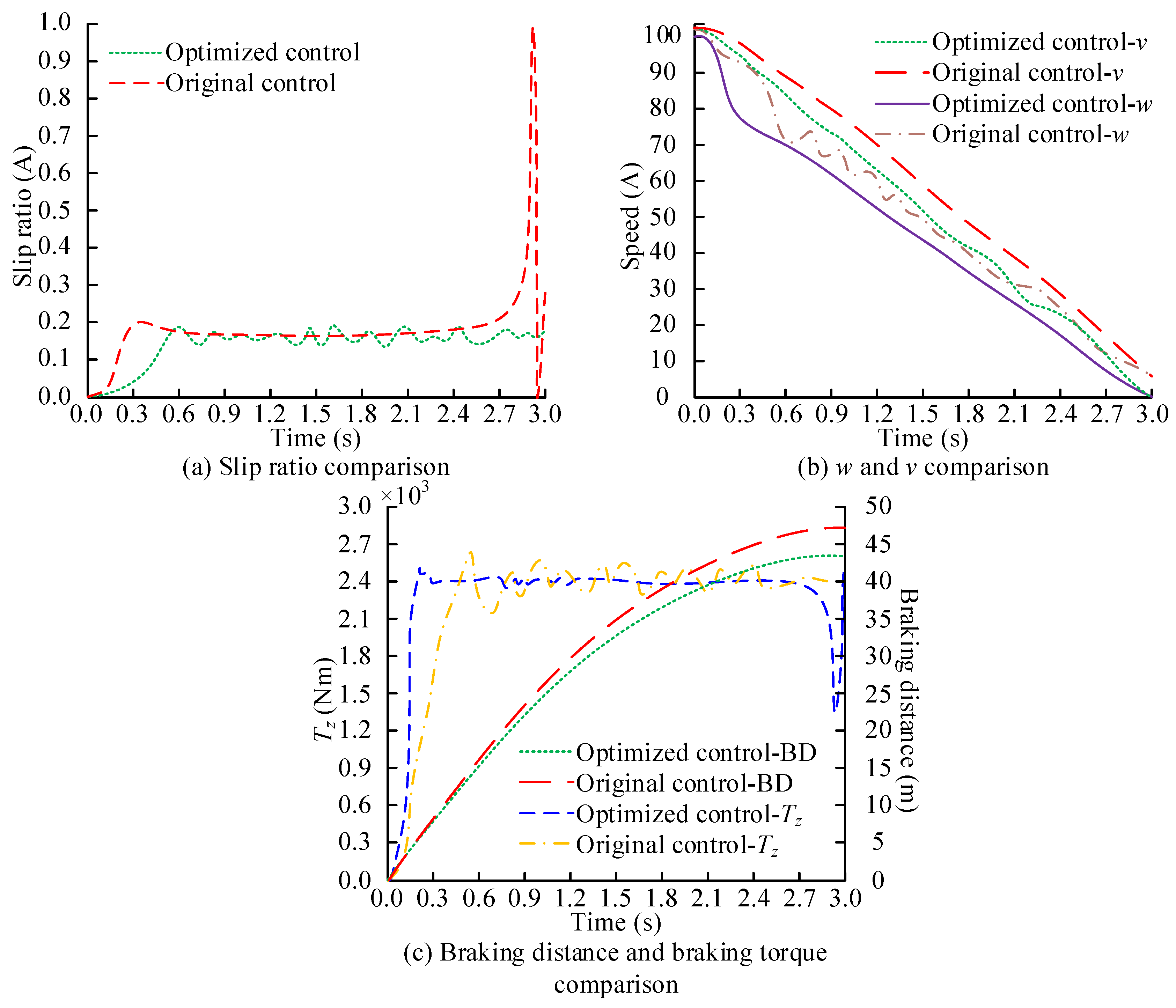
Figure 11.
In
Figure 11 (a), the RMSE of RSMC is 0.06, which is 8.6% lower than TSMC. RSMC can more accurately control the wheel slip ratio near the target value, reduce slip ratio jitter, and improve the stability of the braking system. In
Figure 11 (b), RSMC causes a faster decrease in wheel speed and angular velocity, while the fluctuation of wheel angular velocity is smaller. RSMC can respond to braking demands more quickly, while reducing unnecessary fluctuations during the braking process and improving the smoothness of the braking process. In
Figure 11 (c), compared to TSMC, the optimized RSMC can reach maximum
faster. Meanwhile, the optimized braking distance is relatively small, ultimately reaching approximately 43m at 3.0s.
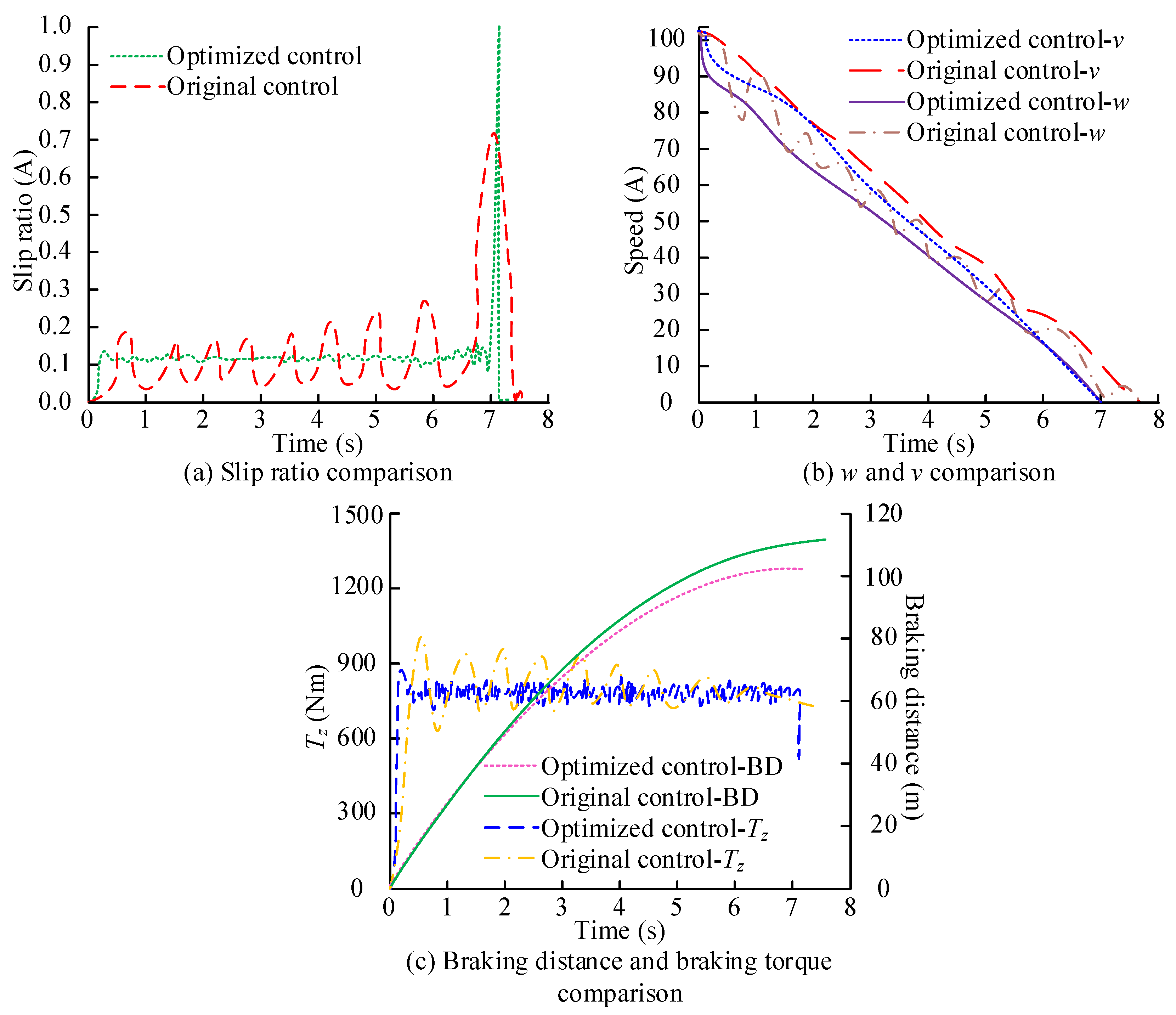
To further validate the effectiveness of the control method, this study conducts tests on local icy roads. Ice road surface represents a slippery road surface with a low coefficient of friction. The comparison under different control methods is shown in
Figure 12.
In
Figure 12 (a), on icy and snowy roads, RSMC has better control performance than TSMC, with a 9.2% reduction in RMSE. This controller performs more stably on low friction road surfaces and can better control the slip ratio of the wheels, thereby ensuring safer braking of the vehicle on such road surfaces. In Figure (b), RSMC intervenes earlier, resulting in a faster decrease in wheel angular velocity and reduced fluctuations in wheel speed. The effectiveness of this controller on slippery roads such as ice and snow can better maintain the stability of the wheels, thereby improving the smoothness and response speed of braking. In
Figure 12 (c), the braking distance on icy and snowy roads has been reduced by 8 meters, and RSMC can effectively improve braking strength and reduce braking distance. This is crucial for improving braking safety. On slippery roads, vehicles are more likely to lose control or experience longer braking distances. The controller can not only quickly respond to braking demands but also reduce overshoot and fluctuations, further improving the braking stability and driving safety of the vehicle.
This study compares road conditions with different friction coefficients and analyzes the control effect of joint control methods on vehicle dynamic behavior under various driving conditions. The initial vehicle speed is set to 102km/h to simulate emergency braking scenarios. The vehicle adopts a designed joint controller to adjust the distribution of four-wheel braking force. The friction coefficient on the left side is 0.2, compared to the road surfaces with friction coefficients of 0.4 and 0.6 on the right side.
Table 3 shows the effectiveness of the joint control method.
In
Table 3, on a road surface with a friction coefficient of 0.4, the maximum lateral braking deviation of the joint controller is 0.148m, while the optimal slip ratio control value for low adhesion roads is even higher at 0.243m. The joint controller can better reduce the lateral deviation and improve the stability of the vehicle, and perform well under low friction conditions. The longitudinal braking distance under this control is 153.4m, while the optimal slip ratio control method for low adhesion road surfaces is a longer 113.2m. At lower friction coefficients, the joint controller provides more efficient braking performance. The joint controller effectively reduces the lateral displacement of the vehicle, making it more stable during braking. Meanwhile, this control method can effectively reduce the vehicle's yaw angle and maintain a good driving trajectory.
4. Conclusion
This study first established an EMB system and introduced PSO optimization of ADRC control parameters to improve system control accuracy. Meanwhile, the ABS system was combined to jointly control the braking and steering control of vehicles on multiple types of road surfaces. The results indicated that compared to the original control method, the optimized control method could achieve more accurate slip ratio control. The maximum slip rate errors of the optimization method were 0.0428 and 0.0632. Compared to the original method, it reduced the maximum error by approximately 12.9%. On asphalt pavement, the current RMSE of the optimization method was 2.3522, while the original method was 3.6477. The optimization method reduced current fluctuations, making it more stable and efficient in the control process. The optimization method outperformed the original method under all testing conditions. The optimization method has shown significant advantages in terms of slip rate control accuracy, current consumption stability, and reduction of maximum slip rate error. In the low friction environment of ice and snow roads, the advantages of optimization methods were more obvious, which could provide more stable and safe braking performance and reduce system energy consumption. Therefore, the application of optimization methods in ABS systems will significantly improve the braking effect and driving safety of vehicles under various road conditions. The controller has higher control accuracy and response speed compared to TSMC under different road conditions, which can effectively improve braking performance and safety, reduce unnecessary fluctuations and wear during the braking process, and has important engineering application value. However, this study did not take into account the high hardware costs of high-performance sensors and actuators. Future research can promote standardization of control algorithms, facilitate technology sharing and economies of scale, thereby reducing costs.
References
- Shaojun, L.I.; Yingjie, L.I.; Wei, L.I.; Zhe, X.U.; Guoyou WA, N.G.; Yan, X.U.; Fansheng, J.I.N. Resonance Suppression Method of Vehicle Mounted Lifting Photoelectric Platform. Infrared Technology 2024, 46, 406–412. [Google Scholar]
- Duan S C, Sun J, ‘Frank’Bai X X; et al. Principle design and control of a brake-by-wire actuator featuring magnetorheological clutch. Proceedings of the Institution of Mechanical Engineers, Part D: Journal of Automobile Engineering 2023, 237, 793–802. [Google Scholar] [CrossRef]
- Chen G, Zhao X, Gao Z. Hua, M. Dynamic drifting control for general path tracking of autonomous vehicles. IEEE Transactions on Intelligent Vehicles 2023, 8, 2527–2537. [Google Scholar] [CrossRef]
- Gao B, Zheng L, Shen W. Zhang, W. A summary of parameter tuning of active disturbance rejection controller. Recent Advances in Electrical & Electronic Engineering (Formerly Recent Patents on Electrical & Electronic Engineering) 2023, 16, 180–196. [Google Scholar]
- Wang Y, Hu Z, Li Y, Zhang, X., Cui, Y. Current Predictive Control of Electro-Mechanical Braking System for Unmanned Tracked Vehicles. Transactions of Beijing institute of Technology 2024, 44, 792–800.
- Song B K, Kim J H, Hwang K Y, Lim, M. S. Electro-mechanical characteristics of dual-winding motor according to winding arrangement for brake systems in highly automated driving vehicles. IEEE Transactions on Vehicular Technology 2023, 72, 12524–12539. [CrossRef]
- Zhou S, Liu J, Wang Z, Sun, S. Research on Design Optimization and Simulation of Regenerative Braking Control Strategy for Pure Electric Vehicle Based on EMB Systems. Transactions of FAMENA 2023, 47, 33–49. [CrossRef]
- Xu Z, Gerada C. Enhanced estimation of clamping-force for automotive EMB actuators using a switching extended state observer. IEEE Transactions on Industrial Electronics 2023, 71, 2220–2230. [Google Scholar] [CrossRef]
- Zhao Y, Lin H, Elahi H, Miao, F., Riaz, S. Clamping force sensor fault analysis and fault-tolerant control of the electromechanical brake system. Arabian Journal for Science and Engineering 2023, 48, 6011–6023. [CrossRef]
- Zhao L, Wang N, Xia G, Mei, X., Wang, H., Zhang, D. Regenerative braking torque compensation control based on improved ADRC. Proceedings of the Institution of Mechanical Engineers, Part D: Journal of Automobile Engineering 2024, 238, 1315–1329. [CrossRef]
- Jin H, Gao Z. On the notions of normality, locality, and operational stability in ADRC. Control Theory and Technology 2023, 21, 97–109. [CrossRef]
- Liu L, Liu Y, Zhou L, Wang, B., Cheng, Z., Fan, H. Cascade ADRC with neural network-based ESO for hypersonic vehicle. Journal of the Franklin Institute 2023, 360, 9115–9138. [CrossRef]
- Safiullah S, Rahman A, Lone S A. A second-order ADRC for synchronized frequency-voltage mitigation of EV integrated power system. IETE Journal of Research 2024, 70, 515–530. [CrossRef]
- Madonski R, Herbst G, Stankovic M. ADRC in output and error form: Connection, equivalence, performance. Control Theory and Technology 2023, 21, 56–71. [CrossRef]
- Sui S, Yao Y, Zhao T. Multi-degree-of-freedom Internal Model Control for Optoelectronic Stabilized Platform Based on Sliding Mode Friction Compensation. International Journal of Control, Automation and Systems 2023, 21, 3994–4005. [CrossRef]
- Xi H , Chen B , Chen T , Zhang, X., Luo, M. Envelope trajectory optimization and tracking control for space multi-fingered mechanism. Advances in Space Research 2024, 74, 764–783. [CrossRef]
- Ruizi M, Xu G, Junbao Y G. PMSG offshore wind power system control using SMC and ADRC with fast SVPWM in complicated environment. Electrical engineering 2023, 105, 2751–2767.
- Soleimani A, Farhang Y, Sangar A B. Fusion of deep belief network and SVM regression for intelligence of urban traffic control system. The Journal of Supercomputing 2024, 80, 25685–25709. [CrossRef]
- Anderson E, Fan F R, Jiaqi CaiWilliam HoltzmannTakashi TaniguchiKenji WatanabeDi XiaoWang YaoXiaodong Xu. Programming correlated magnetic states with gate-controlled moire geometry. Science 2023, 381, 325–330. [CrossRef] [PubMed]
- Shen Q, Huang S, Sun B, et al. PVII: A pedestrian-vehicle interactive and iterative prediction framework for pedestrian's trajectory. Applied Intelligence 2024, 54, 9881–9891. [CrossRef]
- Son S J, Meetei T S, Park D K. Wide Optical Beam Steering LCOS Device for Solid-State LiDAR Applications. IEEE Photonics Technology Letters 2024, 36, 35–38. [CrossRef]
- Lee, D.H. Efficient perception, planning, and control algorithm for vision-based automated vehicles. Applied Intelligence 2024, 54, 8278–8295. [Google Scholar] [CrossRef]
- Lancaster P, Mavrogiannis C, Srinivasa S, Smith, J.R. Electrostatic brakes enable individual joint control of underactuated, highly articulated robots. The International Journal of Robotics Research 2024, 43, 2204–2220. [CrossRef]
- Zhu S, Fan X, Qi G, Wang, P. Review of control algorithms of vehicle anti-lock braking system. Recent Patents on Engineering 2023, 17, 30–45. [CrossRef]
- Kong X, Deng Z, Zhao Y, Gao, W. Stability control of distributed drive electric vehicle based on adaptive fuzzy sliding mode. Proceedings of the Institution of Mechanical Engineers, Part D: Journal of Automobile Engineering 2024, 238, 2741–2752. [CrossRef]
- Yin C, Mei Z, Feng Y, Tang, L. A novel traction control strategy for an electric bus. International Journal of Vehicle Performance 2024, 10, 215–237. [CrossRef]
- Yang T, Li P, Li Q, Li, Z. Vehicle stability control strategy for high-speed curves based on mode switching. Proceedings of the Institution of Mechanical Engineers, Part D: Journal of Automobile Engineering 2024, 238, 3825–3842. [CrossRef]
- Gao L, Gao Q H, Cheng H J, Liu, Z., He, X. Multi-body modeling and dynamic analysis of the heavy-load multi-axle vehicle Based on 6S/6M ABS control. Proceedings of the Institution of Mechanical Engineers, Part D: Journal of Automobile Engineering 2024, 238, 491–508. [CrossRef]
- Zeng X, Gao H, Song D, Li, L. Coordinated control algorithm of lateral stability of hybrid electric commercial vehicle. Proceedings of the Institution of Mechanical Engineers, Part D: Journal of Automobile Engineering 2024, 238, 2767–2785. [CrossRef]
- Nagarkar M, Bhalerao Y, Sashikumar S, Sashikumar, S., Hase, V., Navthar, R., Zaware, R., Surner, N., et al. Multi-objective optimization and experimental investigation of quarter car suspension system. International Journal of Dynamics and Control 2024, 12, 1222–1238. [CrossRef]
|
Disclaimer/Publisher’s Note: The statements, opinions and data contained in all publications are solely those of the individual author(s) and contributor(s) and not of MDPI and/or the editor(s). MDPI and/or the editor(s) disclaim responsibility for any injury to people or property resulting from any ideas, methods, instructions or products referred to in the content. |
© 2025 by the authors. Licensee MDPI, Basel, Switzerland. This article is an open access article distributed under the terms and conditions of the Creative Commons Attribution (CC BY) license (http://creativecommons.org/licenses/by/4.0/).