
Submitted:
13 January 2025
Posted:
14 January 2025
You are already at the latest version
Abstract
The efficient operation and maintenance (O&M) of over one million bridges has become a significant challenge for bridge management authorities in China. By establishing a clear and logical workflow framework for bridge O&M and leveraging the web-based cloud platform's advanced data processing and visualization capabilities, this paper proposes a brand-new bridge O&M platform based on the Digital Twin (DT) concept. This platform adopts a three-layer B/S architecture that facilitates seamless interaction through data exchange, forming a stable and reliable architecture. It incorporates a user-friendly interface that visually displays BIM models of bridges and related data, enabling users to intuitively and efficiently access critical information. Furthermore, the platform has integrated a Smart Device module, including drones, to enable precise control and unified management. To improve the efficiency of data querying and acquisition, the data is categorized into five types based on the platform’s functionality. Drawing on the principles derived from the IFC and COBie data models, Shared Information serves as a common resource for constructing other data structures, which also incorporates the concept of metadata and meta-metadata. The data structures for Bridge Basic Information and the Defect are designed as key examples, integrating a master classification table with its sub-tables. This construction method ensures systematic organization, coherence, and standardization of data structures. It significantly enhances data management capabilities, presenting bridge data in greater clarity. Finally, the authors use the Xiaoqing River Bridge as a case study to illustrate the application of the Defect data structure. The foundational architecture for the platform demonstrates a certain degree of innovation by consolidating multiple modules into a cohesive system. Collectively, these advancements will enhance the level of informatization and maintenance efficiency in bridge O&M, thereby improving bridge safety and service life and ultimately generating considerable economic and societal benefits.
Keywords:
Architecture
; Data Structure
; Digital Twin
; Maintenance
; Platform
1. Introduction
Addressing the challenge of efficient operation and maintenance (O&M) of over one million bridges currently in service has become a critical priority for bridge management authorities in China. To meet this pressing need, researchers have undertaken significant efforts, including the development of the Bridge Health Monitoring System (BHMS) and the Bridge Management System (BMS). Among these, the BHMS has emerged as a pivotal tool in the field of bridge monitoring, with its primary objective focused on the real-time monitoring of mechanical parameters and environmental conditions. Researchers have achieved synchronized visualization of real-time sensor data by integrating Multimedia Tools [1] and mitigated the challenges of traditional data silos by utilizing semantic web technologies [2]. To address communication inefficiencies between sensors and systems, a field evaluation methodology for Internet of Things (IoT) systems was developed [3], and the Artificial Intelligence of Things (AIoT) communication framework was reconstructed using Petri net technology [4], leading to significant improvements in the efficiency and accuracy of real-time sensor data transmission. By integrating various pieces of information from bridge O&M, BMS is designed to systematically visualize the bridge's defect and safety status for better decision-making. It integrates a great deal of bridge-related information into a unified model, including model component IDs [5], defect classification and grading [6], bridge condition levels, and corresponding color-coded indicators for varying condition states [7]. In the BMS, this information could be integrated into a structured framework [8], enabling the comprehensive visualization of defect data and operational status with bridge BIM models. Compared to the BHMS, the BMS includes monitoring data and encompasses comprehensive maintenance information, covering inspection, assessment, and decision-making for bridge O&M. Additionally, it enables the visualization of defect data and safety status, significantly enhancing the efficiency of bridge maintenance. Both systems offer valuable technical insights that contribute to advancing the development of future bridge O&M systems.
Over the past decade, cloud platforms have been widely adopted across various industries, driven by the advanced capabilities of web-based technologies in visualization, data processing, and management. For example, a cloud platform for bridge health monitoring was developed using Building Information Modeling (BIM) and Geographic Information System (GIS) technologies [9], demonstrating the feasibility of collaborative management in bridge O&M. Similarly, in hydraulic engineering, WebGL technology has been utilized to enable the synchronized visualization of finite element analysis results on front end interface within a cloud platform [10]. These advancements in web-based technologies provide expanded opportunities for developing innovative platforms across diverse domains.
Based on the authors’ extensive experience in maintenance projects, there remains a pressing need to advance informatization in bridge O&M. Key issues include the standardization of fundamental bridge data, detailed visualization of defect data and bridge status, precise control and unified management of smart devices, efficient processing of big data across thousands of bridges, support for multi-user collaboration, and other related requirements. To address this series of complex issues systematically, this paper proposes leveraging the DT concept and web-based cloud platform technology to develop a brand-new bridge O&M platform. This study will establish systematic interrelationships among various tasks, including smart device management, inspection and monitoring, assessment, and maintenance within a cohesive workflow, and building a foundational architecture for the platform. This study will establish systematic interrelationships among various tasks, such as smart device management, inspection and monitoring, assessment, and maintenance, integrating them within a cohesive workflow and building a foundational architecture for the platform. Furthermore, in-depth research on data organization is imperative, focusing on exploring data classification and data structure organization. The ultimate objective of this platform is to enhance maintenance efficiency, mitigate potential safety risks, and ensure the sustained safe operation of bridges.
2. Related Works
As mentioned, developing a DT-based bridge O&M platform is crucial for managing multiple bridges, although it presents considerable challenges. Reviewing recent research on DT technology and data standards, such as IFC and COBie, could provide valuable insights into overcoming these challenges.
2.1. Digital Twin
Digital Twin (DT) technology has gained widespread adoption across various industries. It facilitates the virtual representation of physical assets, capturing their entire life cycle in real time and providing in-depth insights into system behavior and performance [11]. However, the interpretation and implementation of DT among scholars differ significantly in practice. Some researchers view DT as integrating or comparing physical entities and virtual models. For instance, physical models have been utilized to monitor crack propagation in aircraft wings [12], infer structural strength degradation in bridges through frequency variations [13], manage fatigue in steel bridges [14], perform load testing [15], and assess the condition of cable-stayed bridges [16]. These applications emphasize the relationship between physical entity status and mechanical performance. Beyond these understandings, DT also provides insights into environmental conditions. Examples include modeling sensor locations and their associated data [17], simulating road traffic performance [18], and utilizing mixed reality (MR) devices to seamlessly integrate virtual and real-world bridge condition visualization [19]. Additionally, UAV (Unmanned Aerial Vehicle) and TLS (Terrestrial Laser Scanner) technologies have been employed to present a more realistic representation of bridges in the virtual world. Real bridge cross-sections were reconstructed using point clouds, and detailed models were developed [20,21,22]. These technologies were also utilized to refine and compare 3D models with the theoretical model [23], enabling more accurate surface deterioration assessments and improving bridge maintenance efficiency.
Artificial intelligence (AI) algorithms have been widely applied in DT-based projects. Leveraging the Knowledge Discovery in Databases (KDD) methodology, combined with clustering and association algorithms, researchers have extracted defect characteristics from existing bridges to facilitate the inspection of other bridges, enabling early detection of potential issues and the implementation of proactive preventive measures [24]. Machine learning techniques, including conditional generative adversarial networks (cGANs), have been utilized to address the limitations of deterministic models, which often fail to account for the uncertainties inherent in structural modeling applications [25]. Furthermore, an intelligent agent-based sequential decision-making model has been proposed, employing dynamic programming to predict the condition of bridge components and optimize defect maintenance strategies [26]. In the context of early warning systems under extreme conditions, vulnerability assessments have been conducted, and risk-based maintenance plans have been developed for bridges leveraging the DT concept [27]. Similarly, the DT framework has been applied in tunnel construction safety to implement a four-tier early warning and emergency response system, offering a robust basis for evaluating construction conditions and mitigating risks [28]. These AI technologies, along with early warning and emergency response systems, have provided greater insights into the safety of bridges.
To further improve the efficiency of the bridge O&M system, the department still faces numerous challenges, including technical aspects related to structures, smart devices, and systems [29]. Scholars have also proposed various innovative ideas and frameworks. Some researchers have suggested strategies to enhance maintenance systems' reasoning capabilities by applying Semantic Web Technologies [30,31]. In contrast, others have introduced a DT maturity model and established a hierarchical evaluation framework using Key Performance Indicators (KPIs) [32]. Furthermore, comprehensive reviews of the existing literature have identified future trends in the application of DT, such as software interoperability, the performance of anomaly detection algorithms, and macro-scale integration [33]. Additionally, a multi-layered DT framework has been proposed, combining decision support systems with data fusion technologies to strengthen decision-making capabilities [34].
The authors propose a conceptual diagram for developing the bridge O&M platform using the DT concept to ensure its operational efficiency. Researchers may integrate AI technologies and construct a highly efficient framework to enhance the platform's intelligence. As shown in Figure 1, the physical bridge utilizes manual methods and smart devices, including drones, robots, TLS, and sensors, to complete inspection and monitoring tasks and collect relevant data. In addition to these data, as-built data, maintenance data, assessment data, and knowledge data can also be acquired from the maintenance department and relevant domain knowledge. These technologies and data are systematically integrated into a unified platform, fusing physical bridge-related information into a virtual environment.
2.2. IFC and COBie
IFC (The Industry Foundation Classes) and COBie (Construction-Operations Building Information Exchange) standards are often used to efficiently convert and transmit BIM models and facility data while developing the O&M system in various domains. This review aims to illustrate their applications in data representation and exchange, thereby establishing a robust foundation for future research on data organization.
2.2.1. IFC
IFC standard offers a unified digital framework for representing infrastructure and environmental data, enabling seamless information exchange across different platforms. In some studies, IFC is employed to model various bridge components [35] and structural defects, such as concrete cracks [36] and spalling damage features [37], with these defects being simulated using the BIM software Revit [38]. In the building domain, IFC is utilized to simulate mechanical states within BIM models [39], address technical challenges in applying IFC models for apartment rights registration within 3D land management systems, and integrate BIM models with broader management processes [40].
The IFC data schema architecture is structured into four conceptual layers, which are organized hierarchically from bottom to top: the Resource Layer, Core Layer, Shared Layer, and Domain Layer. The Resource Layer encompasses schemas that define fundamental resources, such as geometry, time, and materials, serving as basic objects referenced by higher-level schemas. By leveraging efficient data schema architecture and a proprietary graphics engine, the bridge O&M platform can incorporate BIM models in IFC format to optimize data transmission efficiency.
2.2.2. COBie
COBie is an open standard for information exchange specifically developed for construction projects and facility management. Its primary objective is to streamline the management and delivery of information across the entire building’s lifecycle. Currently, COBie is predominantly utilized in the facility management of building assets, providing O&M data sourced from designers, contractors, installers, and manufacturers. The standard is most implemented as a spreadsheet, encompassing spatial information, equipment information, build information, and common information. Notably, common information serves as a shared resource, supporting and enhancing the integration of other data types.
The application of COBie spreadsheets in the facility management of BIM models has gained widespread adoption, extending not only to the building domain [41,42] but also to ports [43] and tunnels [44]. COBie is a structured data format that consolidates non-geometric attribute information generated throughout various stages of the project lifecycle. This standardized format enables stakeholders at each project phase to efficiently input and retrieve the required non-geometric data, facilitating seamless information exchange and fostering collaborative data sharing.
Leveraging insights from DT technology and the IFC and COBie standards, this paper will adopt the DT-based concept and data architecture principle to establish a more robust framework and an organized and systematic data structure for the bridge O&M platform. These aspects will be further studied in the subsequent chapter.
3. The Architecture for the Platform
3.1. The Maintenance Workflow
During the process of constructing the workflow framework for bridge O&M, the authors systematically examined the interrelationships among various tasks and explored the key elements of each task type based on relevant Chinese standards and publications. These resources provide detailed classifications of task types and their relationships [45,46]. By analyzing these reviewed resources with project experience, the study team outlined various tasks to be considered in the workflow, including smart device utilization, inspection, monitoring, assessment, design, construction, and more. Different tasks are often carried out alternately in practice, which further increases the complexity of maintenance management. Therefore, it is crucial to establish a clear and logical O&M workflow. Such a workflow will not only enhance the efficiency of data utilization but also facilitate the optimization of platform functionalities and improve the platform’s user experience. This chapter has systematically organized the bridge O&M workflow into six key steps, as outlined below.
Step1: Data Collecting
The collection of comprehensive foundational data is the initial step in bridge O&M and serves as the foundation of the entire maintenance process. Before the maintenance starts, it is essential to gather static data on the bridge, including Design data, Construction data, Supervisory data, Facility data, etc. These data encompass design drawings, calculation models, construction methods and processes, supervisory reports, change records, and documentation of bridge facilities. Additionally, dynamic data generated throughout the bridge's operational lifecycle must be gathered, such as Maintenance data, Inspection data, and Monitoring data. These records of bridge maintenance during its operational phase are crucial for enhancing management authorities' decision-making precision. Furthermore, Knowledge data, including design and construction standards, assessment methods, and expert knowledge, provides a scientific foundation for informed decision-making in the bridge assessment process.
Step2: Inspection And Monitoring
Following the completion and acceptance of a bridge, it enters the bridge O&M phase. During this phase, the bridge maintenance department formulates a scientifically rigorous and well-structured inspection and monitoring plan for each bridge. This plan includes operational methods, requirements, work schedules, and other pertinent details. Inspection activities are typically categorized into four types: Regular inspection, Periodic inspection, Special inspection, and Load testing, which are carried out by specialized teams.
Monitoring is a prominent area of research. It involves the use of sensors and systems that provide real-time data on the bridge's structural conditions. Such monitoring systems are generally integrated post-construction or during maintenance based on specific requirements. Key monitoring targets include Structural performance, Environmental conditions, Load, and Traffic.
To enhance the efficiency of bridge O&M, smart devices have increasingly become essential tools for both Inspection and Monitoring, playing a vital role in modern bridge O&M. Commonly utilized smart devices in the maintenance process include drones, robots, scanning devices, sensors, and other advanced devices. These tools significantly contribute to improving the accuracy and reliability of bridge O&M.
Step3: Status And Safety
Based on the collected Inspection and Monitoring data, it is necessary to assess the bridge’s Status and Safety in the next step. This process involves analyzing the existing defects on-site to identify their type, dimensions, quantities, severity, problem diagnosis, and cause analysis. These analyses are subsequently compiled into a comprehensive damage analysis report. Engineers are also required to assess the operational and structural condition of the bridge using standardized scoring methods, such as the Bridge Condition Index (BCI) and Bridge Structure Index (BSI), in accordance with maintenance standards, to assign corresponding condition scores. During this process, a finite element model is simultaneously developed to calculate and verify the bridge's mechanical performance. The results are then integrated to perform the safety assessment, lifetime prediction, and remaining capacity estimation for the overall bridge and its components. This culminates in the formulation of reliable maintenance recommendations and the preparation of a detailed professional assessment report. These works constitute the complete process for assessing the Status and Safety of a bridge. A scientifically sound assessment report forms the foundation for making well-informed and rational maintenance decisions.
Step4 & Step5: Maintenance Decision and Maintenance Operations
Upon receiving the assessment report, the bridge management department must undertake decision-making and formulate a maintenance strategy. The scope of maintenance operations encompasses routine maintenance, medium-sized maintenance, overhaul maintenance, strengthening and retrofitting, and reconstruction and extension works. Routine maintenance can typically be carried out promptly by the established bridge maintenance plan. In contrast, medium-sized maintenance and overhaul maintenance necessitate adherence to formal construction procedures, including the selection of design, construction, and supervision companies through a competitive bidding process. Maintenance operations should be carried out in alignment with the approved design plan, and the entire process requires the involvement of specialized teams to ensure effective cost control. Upon completion of the maintenance work, formal acceptance must be conducted before the bridge can be returned to service.
Step6: Data Archiving and Delivery
At the end of each maintenance cycle, the data generated throughout the maintenance process must be systematically organized and archived into a database or repository to ensure the establishment of a comprehensive maintenance record. After maintenance, the bridge will be handed over to the bridge maintenance department for continued use.
During the bridge O&M phase, supplementary inspection and monitoring are conducted to address potential defects not identified in earlier stages. This enables timely documentation and rapid assessment of newly discovered bridge defects. Within a short timeframe, corresponding repair plans are developed and implemented.
Additionally, management techniques are integral to the bridge maintenance process, encompassing task management, project management, data management, organizational management, personnel management, equipment management, and more. Establishing an efficient management framework ensures a rapid response to bridge defects, thereby enhancing the overall efficiency of bridge maintenance and effectively safeguarding the continued safe operation of the bridge.
The authors have established the framework of the workflow for bridge O&M, as shown in Figure 2. It clearly illustrates the six steps of the maintenance process, with each step being closely interconnected. The maintenance data, workflow logic, and management techniques across these steps collectively form the operational framework for bridge O&M. The data gathered from Inspection and Monitoring serves as the foundational basis for assessing the bridge's Status and Safety. The scientific assessment report subsequently provides crucial decision-making support for the bridge department in developing maintenance strategies. Following the completion of the decision-making process, the maintenance company is required to undertake appropriate maintenance operations. Throughout this maintenance workflow, integrating management techniques ensures the efficient and seamless execution of operations. It is evident that acquiring accurate Inspection and Monitoring data, coupled with scientifically grounded Status and Safety assessment methodologies, forms the cornerstone of bridge maintenance operations. This not only provides a solid foundation for bridge decision-making but also establishes the technical groundwork for subsequent maintenance operations.
3.2. The Architecture, Data Processing and Visualization, and Front-End Modules for the Platform
The web-based cloud platform represents a widely adopted 3D digital information management technology that seamlessly integrates Building Information Modeling (BIM) and internet technologies. It enables global users to access and interact in real-time through a dedicated graphical engine within a web browser and facilitates the integration of multiple systems, databases, and applications. Based on the advanced capabilities of the web-based cloud platform, the framework of the workflow for bridge O&M, and the DT concept, the authors have developed the architecture for bridge O&M platform. It adopts a three-layer design based on the B/S (Browser/Server) model, as shown in Figure 3. This chapter provides a comprehensive analysis of the content and logical relationships at each layer, the processes involved in data processing and visualization, and the hierarchical structure of the front-end modules.
3.2.1. The Three-Layer Architecture
The platform architecture is structured into three distinct layers, arranged from top to bottom: the User Interface Layer, the Logic Layer, and the Data Layer. These layers are tightly integrated and work in synergy to enable the platform's functionalities. The lower layers provide transparent and reliable services to the upper layers, while the operations of the upper layer remain independent of the specific forms of the lower layer. Interaction between layers occurs through well-defined information interfaces.
The Top Layer: The User Interface Layer
The User Interface Layer establishes efficient interaction between users and the platform by offering web-based services, processing user requests, and delivering the corresponding execution results. On the front-end interface, users are provided with an intuitive means to visualize and interact with BIM models and associated data. This layer is primarily responsible for the visual representation of data stored in the Data Layer and processed by the Logic Layer.
Based on the framework of the workflow for bridge O&M, eight core operational modules for the bridge O&M platform have been identified, excluding the Home module. These modules include Inspection and Monitoring, Status and Safety, General Maintenance, Strengthening and Retrofitting, Smart Devices, Task Management, Capability Center, and Database Management. The first four modules are classified as technical modules, while the remaining four are categorized as management modules. The interrelationships among the technical modules follow the logical workflow of inspection and monitoring, safety assessment, general maintenance, strengthening, and retrofitting. The management modules, in turn, provide essential managerial support to the technical modules. Additionally, a dedicated Smart Devices module is implemented with the Inspection and Monitoring module, such as drones, robots, scanning devices, and sensors. This module enables users to achieve precise control and unified management over the associated smart devices.
As shown in Figure 4, the front-end interface adopts a simple and user-friendly design style, with the 3D digital model of the bridge and related information displayed intuitively in the lower-right corner, occupying the primary area of the page. This layout significantly enhances the visualization of the platform. The left side of the interface is allocated to the main module area, representing the nine core modules of the platform. Users can interact with this section by dragging the arrow to toggle the visibility of these modules, thereby enhancing the overall user experience. The central right section features sub-modules, enabling users to select and explore specific functionalities in greater detail. Additionally, the overall bridge and user information are positioned in the upper-right corner, offering an intuitive overview of the bridge's current location and the user’s details. By minimizing visual clutter and streamlining operations, the design enables users to efficiently and intuitively access relevant information, thereby improving the platform’s usability and user experience.
The Middle Layer: The Logic Layer
In the B/S architecture, the Logic Layer functions as the intermediary between the User Interface Layer and the Data Layer. It processes requests from the web interface, executes the corresponding business logic, retrieves data from the database, and returns the processed results for display on the web interface, thereby facilitating efficient data exchange between the front-end and back-end. This layer encompasses the business logic, data processing logic, and interface logic, among other components. It contains multiple validated algorithm programs, including those for data processing and visualization, model lightweight, point cloud processing, image processing, flight path planning, level assessment scoring in specifications, threshold discrimination, machine learning, and various other AI algorithms.
The Bottom Layer: The Data Layer
The Data Layer stores the foundational data, computational programs, and method libraries of the platform, as well as the entire process data associated with platform operations and computations. As the lowest layer of the platform architecture, it is responsible for the fundamental operations on raw data, recording the data extraction processes and computational outcomes from the Logic Layer, and handling data requests, access, updates, and maintenance from the User Interface Layer. Key components include the Basic Information Database, Management Document Database, Inspection and Monitoring Database, Acquisition and Processing Database, Devices Database, Capability Center Database, Technical and Methodology Database, Engineering Cost Database, Data Dictionary Database, and User Management Database, among others. The Data Layer not only ensures the accurate and reliable functioning of the platform by providing essential data support but also establishes a robust foundation for the development and optimization of higher-level applications.
3.2.2. Data Processing and Visualization
The primary function of the platform is to provide a visualization of data from the Data Layer, facilitating efficient querying and acquisition by users. Data originates from the Data Layer, undergoes processing in the Logic Layer, and is subsequently presented in the User Interface Layer. Alternatively, data can be entered through the User Interface Layer, processed in the Logic Layer, and stored in the database. Additionally, data may be transmitted directly from the Data Layer to the User Interface Layer for visualization or stored directly in the Data Layer from the User Interface Layer.
Within the Data Layer, data is categorized according to the platform’s functional requirements, including Management Data and Shared Data, Model Data, Inspection and Monitoring Data, and Status Data. Management Data and Shared Data can be visualized directly in the front end without passing through the Logic Layer, whereas the other three data categories require algorithmic processing before visualization.
This structured and hierarchical architecture facilitates smooth data flow, enhances system flexibility, and supports efficient querying and processing at each step of the maintenance workflow.
3.2.3. The Hierarchical Structure of the Front-End Modules
The modular design of the platform’s front-end interface adheres to the principles of the architecture, as shown in Figure 5. The hierarchy of front-end modules follows a top-down, drill-down feature, progressing from Module to Sub Module, Assembly, Sub Assembly, Data Object, and ultimately to Data Sheet. This hierarchical feature facilitates efficient querying and retrieval of platform modules and associated data. The transparent relationships between each level, coupled with the robust technical architecture provided by the web-based cloud platform, not only streamlines the addition or modification of module functionalities but also enhances the scalability and extensibility of both modules and assemblies.
The bridge O&M platform presented in this paper represents an innovative integration of smart devices, inspection and monitoring, assessment, and maintenance operations into a unified system. By harnessing the robust technical infrastructure of the web-based cloud platform, the platform enhances the acquisition, processing, storage, visualization, and management of data across different maintenance phases. This foundational architecture significantly improves engineers' efficiency by addressing technical challenges within a single platform. Ultimately, this platform strengthens the informatization of bridge O&M throughout its lifecycle, providing a solid foundation for the future integration of AI technology.
4. The Data Structure for the Platform
As bridges' operational lifespans increase, data accumulation over time generates a substantial volume of maintenance records. To enhance the platform's efficiency, it is essential to develop an effective method for organizing the data. Before researching this method, the study team comprehensively investigated relevant BIM data technology standards in China. These include a proposed set of information model requirements for applying BIM technology across the entire lifecycle of highway projects [47], as well as well-defined data standards for project models during the design, construction, and maintenance phases [48,49,50,51]. Moreover, some standards systematically define key monitoring parameters and propose early warning standards and recommended measures [52]. Standardized requirements have also been established for sensor equipment information, monitored data objects, and data source formats [53,54]. Although these standards provide detailed specifications for model and sensor data, they lack in-depth on how to organize the data commonly used in the bridge O&M platform. This chapter will address this critical research gap by exploring the issue further.
4.1. The Classification of the Data
According to the platform's three-layer architecture in Chapter 3.2.1, the data are derived from the characteristics of commonly used information in bridge maintenance. The platform data are categorized into five functional types: Shared Information, Management Information, Model Information, Inspection and Monitoring Information, and Status Information, as shown in Figure 6.
To achieve a more optimized data structure, the authors examine the data structure principles outlined in both the IFC and COBie standards. It is evident that the resource layer of the IFC standard and the common information layer of the COBie standard both define the fundamental elements of their respective data structures. In the data structure presented in this paper, the study team will adopt these data architecture concepts to enhance data organization efficiency.
In Shared Information category, several common resources are identified: Size and Material, which define the fundamental properties of objects; Location and Geometry Coordinates, representing the spatial positioning of objects; Personnel and Organization, capturing detailed information about management and staff; Attribute, recording specific data features to enhance data management and interoperability within the platform; File, representing records stored in various formats that contain detailed information; and Environment, Road, and River, specifying the boundary conditions of the bridge; and Facility, describing information related to ancillary elements on the bridge, such as pipelines, traffic signs, and other infrastructure. These elements of Shared information serve as a common resource within the platform, constituting a fundamental component for other types of information.
Various components are included within the Management Information domain, such as daily task management, meeting management, announcement management, and construction process management (encompassing tendering and bidding, design, construction, supervision, and acceptance). Additionally, smart device management, including drones, robots, and other technologies, is also covered.
Also, the platform incorporates Model Information to represent various model details, including the BIM model, Mechanical model, and Scanned model. The BIM models consist of four main categories: Bridge model, Smart Device and Facility model, Ground surface model, and Geological model. Each BIM model comprises multiple BIM Components, each containing a variety of BIM Geometric Elements. To display Mechanical information on the front end, the Mechanical Model must also be defined, which includes key elements such as Mechanical Geometry, Mechanical Loads, Mechanical Constraints, and Mechanical Results. Furthermore, the Scanned Model, obtained through laser scanning and drone scanning technologies, primarily consists of Scanned Components and Scanned Geometric Elements.
Additionally, it is essential to identify the most critical data, namely Inspection and Monitoring Information, which is comprised of three components: Smart Device Control, Inspection, and Monitoring. Smart Device Control primarily records data related to the control of devices used during the inspection process, including the Control Type, Control Parameters, and Working Path. This information enables precise control and unified management of smart devices. Inspection mainly captures information about defects on the bridge, including the Defect, Defect Type, and Defect Criteria, among other relevant details. Monitoring encompasses four key areas: Monitoring Structural Parameters, Monitoring Environment, Monitoring Load, and Monitoring Traffic. Monitoring Structural Parameters includes measurements such as deformation, acceleration, stress, and strain. Monitoring Environment covers variables such as temperature, humidity, wind speed, and atmospheric pressure. Monitoring Load involves data on vehicle loads and pedestrian loads. Finally, Monitoring Traffic records the load performance of vehicles and pedestrians, categorized by type. With the advancement of technology, additional technical aspects may be monitored, and the platform can expand its monitoring capabilities to accommodate these developments.
Status Information is another critical aspect of our focus, which includes Structural Status, Operational Status, and Maintenance Status. To facilitate quick identification and analysis, the platform utilizes a color-coding system to visualize the differences between various status levels.
Among the five types of information mentioned above, Shared Information serves as a common resource for constructing other data structures within the platform. This method not only organizes the data structure systematically but also significantly enhances data utilization efficiency.
4.2. The Organization of the Data Structure
This chapter will explore the method for constructing the platform's data structure, offering a comprehensive overview of its systematic establishment within the database. The construction of this data structure leverages the concept of metadata, commonly described as "data about data," as it defines and provides context for other data. In the process of developing detailed bridge maintenance data, metadata has been utilized to impose normative constraints and management on the data. Additionally, the authors further analyze the fundamental aspects of metadata, referred to as "meta-metadata." The subsequent sections will present an in-depth exploration of this method.
4.2.1. The Data Structure of Shared Information
The primary purpose of Shared Information is to function as a common resource for other data, similar to the background context of those data. Therefore, during the construction of such data structures, it is essential to examine the meta-metadata of the data, which describes the context or background of the metadata. For example, in the case of the context '20.25m,' the metadata indicates that the background refers to Bridge_Standard_Width and Width. In constructing the data structure, the metadata for Bridge_Standard_Width and Width include the attributes size_name and size_type. Consequently, size_name and size_type are defined as the meta-metadata for the field '20.25m.' Continuing with these concepts, the metadata associated with the context '20.25' is identified as size_value, with a data double. Correspondingly, the metadata for the context 'm' is designated as size_unit, with a varchar data type and a data length limit of 255, as shown in Figure 7.
Thus, in the database, the data structure for Size should include attributes such as size_id, size_type, size_name, size_description, size_value, size_unit, and so on. A unique identifier, size_id, is assigned to each record to ensure distinct identification. The size_type attribute defines various categories of size, including Length, Width, Height, Depth, Increment, Area, Volume, File size, and so on. The size_type encompasses not only geometric dimensions but also non-geometric data, such as file sizes.
The construction process of the Size data structure is described above. This approach can similarly be applied to other data within the Shared Information, including Material, File, Location, Geometric Coordinates, Attribute, Personnel, Organization, Environment, Facility, and other relevant categories. In the Material data structure, elements such as material_type and property_name are defined. The material_type attribute stores information about the types of materials, such as Steel, Concrete, Wood, Aluminum, and so on. The property_name attribute, on the other hand, stores the names of material properties, including Weight, Poisson's Ratio, and Elasticity Modulus, among others that are commonly required data in the Mechanical Model. In the File data structure, the file_type attribute encompasses a range of data formats, including TXT, Document, Image, Audio, Video, Drawings, Model, RAR, and other frequently used file formats. Similarly, the Attribute data structure, the attribute_type field, and the Environment data structure, the environment_type field, both contain diverse types of data structure elements corresponding to their respective categories. The detail of the data structure for the Shared Information has been constructed, as shown in Figure 8.
Bridge Basic Information can also be referred to as the Bridge Information Card, which is a document or electronic record used to capture and manage information related to bridges. Its purpose is to centralize a bridge's essential data, technical specifications, and maintenance information, thereby enabling engineers, managers, and other relevant personnel to access and utilize this information quickly. In the following section, the authors will use Bridge Basic Information as an example to demonstrate how different data structures from Shared Information are used as common resources to construct other data structures. The relationship between the Bridge Basic Information classification table and its sub-tables has been established, as shown in Figure 9.
Bridge Basic Information defines corresponding data structures of sub-tables based on different classifications. All these data structures collectively form the complete data structure of Bridge Basic Information. The classification table includes at least seven categories: Bridge_ID, Bridge_Attribute, Bridge_Size, Bridge_File, Bridge_Organization, Bridge_Location, and Bridge_Facility. Except for Bridge_ID, the other six categories correspond to the Shared Information categories: Attribute, Size, File, Organization, Location, and Facility. Each sub-table independently defines data structure elements. For instance, in the Bridge_Attribute table, the General Attribute type defines elements such as CreatedBy, CreatedTime, Bridge_Type, Bridge_Name, Bridge_Color, and Bridge_Description, which are further specified under attribute_name in the Attribute table. Additionally, in the Bridge_Organization classification table, the Organization_Type field presents various types of companies, including Management Department, Design Company, etc. Similarly, the Facility_Type field in the Bridge_Facility classification table includes different kinds of facilities, such as Water Pipeline and Gas Pipeline. This classification-based method for representing data structures optimizes their hierarchical organization, deepens the understanding of their inherent meaning, and enhances the efficiency of data querying and acquisition.
The data structure tables for Bridge Basic Information have been defined in the MySQL database, with Navicat Premium serving as the database visualization and management tool, as shown in Figure 10.
The process of constructing the database can be broadly divided into seven steps: (1) First, create the classification table for Bridge Basic Information and the corresponding sub-tables in the database. The table names are derived from the Shared Information classification categories, with all tables initially empty. (2) Next, complete the Bridge Basic Information classification table and populate the basic information_class column with the specific classification elements. Design the table by adding other fields such as basic information_id, bridge_id, bridge_name, etc. (3) Design the data structure elements for the size table, including fields such as size_type, size_name, size_description, and others. (4) Return to the size table and input the required data. In the size_class column and size_bridge_name column, specify the classification Bridge_Size and Xiaoqing River Bridge, thus establishing a link between the classification table and the sub-table. (5) Using a similar approach, design the size_type table and input the relevant data. A foreign key is used to link the size_type column in the size table to the size_type_context in the size_type table, facilitating the selection of size_type data within the size table. (6) Repeat steps (3) to (5) to complete the remaining sub-tables for Bridge Basic Information. (7) Finally, the relationships between the data are verified to ensure no errors will be present, thus completing the creation of the data structure tables of Bridge Basic Information.
In the construction process of the data structure described above, the sub-table Bridge_Size elements of Bridge Basic Information are stored in the sub-table size of Shared Information, and the link between the master classification table and the sub-tables is established through the sub-table size elements size_class and size_bridge_name. Such a method clearly demonstrates the hierarchical and systematic characteristics of the data structure, thereby ensuring its coherence and standardization.
4.2.2. The Data Structure of the Defect
When representing the defect data, these datasets incorporate Shared Information as common resources while also encompassing four other distinct categories of information within the organizational framework of the platform’s data, as shown in Figure 6. This chapter illustrates the detailed organizational method of such data structures by showing an example of Defect in Inspection and Monitoring Information.
As shown in Figure 11, the Defect data structure includes Shared Information, Management Information, Model Information, and the Defect Criteria from Inspection. Within the Attribute section, Defect_Type defines all defects encountered on bridges, such as carbonation, corrosion, shrinkage cracking, bending cracking, spalling, pitting, and others. The Defect_Size section primarily details the dimensions of the defect, including Length, Width, Height, and Depth. Furthermore, the location of the defect is carefully documented, including Defect_Location, Defect_Coordinates, and Defect_Inspect_Person. Defect_File serves as the record file for defect data.
In addition to the aforementioned information, it is essential to document the smart devices used in the process, referred to as Defect_Device, within the Management Information section. The bridge BIM model and the defect model, which are related to the defect, are recorded under the Defect_BIM Model information. Related_Component_ID and Related_Component_Name capture the ID and name of the model components associated with the defect, thereby facilitating the querying and visualization of defects. Furthermore, Related_Geometry_Element_ID and Related_Geometry_Element_Name document the ID and name of the geometric elements corresponding to the defected components, including the top surface, bottom surface, lateral surface, and inner surface of the girders, among others.
To evaluate the severity of defects, Defect Criteria information is established, comprising the Defect_Criteria_Name, along with its associated Defect_Criteria_Threshold_Value, Defect_Criteria_Threshold_Unit, and Defect_Criteria_Level. Defect_Criteria_Level encompasses three categories: slightly damaged, medium damaged, and severely damaged. These clearly defined damage levels are displayed on the platform, facilitating informed maintenance decision-making by the bridge department manager.
The data structures for Bridge Basic Information and the Defect are carefully designed as representative examples by integrating a master classification table with its sub-tables. The composition of the data structure ensures systematic organization and coherence while promoting a high level of standardization. Additionally, it facilitates a deeper understanding of the inherent relationships within the data for maintenance engineers, laying a solid foundation for further visualization, analysis, and decision-making for the bridge maintenance department.
5. Case Study
5.1. General Information About the Bridge
The authors selected the Xiaoqing River Bridge, with a total length of 1032.52m, as the case study object for the development of the bridge O&M platform. This super-large bridge is located on the expressway in Jinan, Shandong Province. The main bridge has a span configuration of 75m + 130m + 75m and is designed as a twin bridge. Each bridge has a width of 20.25 meters, with four traffic lanes. The bridge components are categorized from bottom to top into the substructure, superstructure, and ancillary elements. The substructure consists of piles, pile caps, and piers. The superstructure consists of a continuous concrete box girder constructed using the cantilever casting method and includes segmental girders, steel tendons, and reinforcing steel. Ancillary elements encompass the asphalt pavement layer, waterproofing layer, crash barriers, bearings, and other associated components, as shown in Figure 12.
5.2. The Details of the Bridge Crack
In the regular inspection process, the engineer employs a drone to capture images of the bottom surface of the mid-span of the Xiaoqing River Bridge, obtaining a series of valid inspection photos and recording the location information along with the drone’s shooting parameters. Subsequently, the engineer applies image processing techniques to analyze the inspection photos, identify potential defects, and generate defect vector maps. This section presents the shape of the crack, along with the BIM model, crack chart, detailed crack data table, and crack severity level within the bridge’s O&M platform, combined with the established defect data structure mentioned above, as shown in Figure 13.
In the platform’s visualization area, the analyzed 2D crack vector image is mapped onto the BIM model according to the location information of the drone. A local coordinate system for the bottom of the segmental concrete girder is established, displaying the X and Y axes, scale markers, and the origin. The total length of the girder’s bottom surface is 4.5 m, with a transverse width of 12.25 m. The associated crack chart and detailed crack data table are immediately displayed when clicking on the crack vector image. The crack chart further refines the crack’s morphology, recording the polyline vector representation of the crack, along with the coordinates of the starting point (Crack P1: xp1, yp1) and the ending point (Crack P2: xp2, yp2) as well as the vector line segment connecting the start and end points. The detailed crack data table presents information that directly corresponds to the Defect data structure, including ten categories of sub-information: ID, Attribute, Size, Location, Coordinates, Inspecting Person, File, Device, Related BIM Model, and Criteria.
The Crack severity level within the Criteria information indicates the extent of crack damage. The classification is determined based on the following criteria outlined in the Crack severity level identification table, as shown in Table 1.
1. When the crack width is less than or equal to 0.2mm, or the ratio of the crack length to surface width is less than or equal to 1/3, the crack severity level is classified as 'Slightly damaged.'
2. When the crack width ranges from 0.2mm to 0.5mm, or the ratio of the crack length to surface width lies between 1/3 and 1/2, or if the crack is identified as the structural crack, the crack severity level is classified as 'Medium damaged.'
3. When the crack width exceeds 0.5mm, or the ratio of the crack length to surface width exceeds 1/2, and the crack is classified as a structural crack, the crack severity level is classified as 'Severely damaged.'
This classification process is implemented using the SQL programming language within the MySQL database. The logic clearly outlines the criteria for assessing crack damage severity, with the platform automatically applying these rules and displaying the results in the data table.
This case study thoroughly demonstrates the process of establishing a well-structured defect data structure and presenting it on the front end. This method effectively addresses issues such as vagueness in defect identification and inaccuracies in location data from inspection results. The refined representation of crack defects provided by this method offers engineers robust visual technical support while also supplying data-driven insights for evaluators and decision-makers. This significantly enhances the scientific accuracy and reliability of bridge maintenance decision-making.
6. Conclusions and Future Work
This paper explores the challenges associated with the informatization of modern bridge O&M. It systematically forms a clear and logical workflow framework for bridge O&M, leveraging the web-based cloud platform's advanced data processing and visualization capabilities. Based on the DT concept, the platform has established a three-layer design following the B/S (Browser/Server) model, comprising the User Interface Layer, the Logic Layer, and the Data Layer. These layers interact seamlessly through data exchange, forming a stable and reliable architecture. The platform incorporates a user-friendly interface that visually displays BIM models of bridges and related data, enabling users to intuitively and efficiently access critical information. Furthermore, the platform has integrated a Smart Device module for precise control and unified management of smart devices, such as drones, thus addressing existing gaps in the informatization of bridge O&M within this domain.
The platform's data is systematically categorized into five types based on functionality to enhance the efficiency of data querying and acquisition. Shared Information is leveraged as a common resource, facilitating the development of other data structures within the platform in accordance with the principles derived from the IFC and COBie data models. The concepts of metadata and meta-metadata are employed in constructing the data structure. The data structures for Bridge Basic Information and the Defect are presented as key examples by integrating a master classification table with its sub-tables. This method provides a more systematic and precise representation of the data while also ensuring coherence and standardization and enhancing maintenance engineers' understanding of the interrelationships within the data.
Finally, the authors use Xiaoqing River Bridge as a case study to illustrate the application of the Defect data structure. The refined crack defect representation provides engineers with strong visual support and offers data-driven insights for evaluators and decision-makers. This case demonstrates that this method can efficiently improve the scientific accuracy and reliability of bridge maintenance decisions.
From an alternative perspective, the platform, drawing on the authors' extensive experience in maintaining projects over the years, integrates smart devices, inspection and monitoring, assessment, maintenance, and construction processes into a cohesive system. It enables seamless data sharing and optimized resource utilization across various phases of bridge O&M. This foundational architecture demonstrates a certain degree of innovation. The data structure organization method, utilizing metadata and meta-metadata concept with a master classification table and its sub-tables, significantly enhances data management capabilities, presenting bridge data in greater clarity and improving the efficiency of integration, interoperability, and traceability. Collectively, these advancements will enhance the level of informatization and maintenance efficiency in bridge O&M, thereby improving bridge safety and service life.
The article still exhibits the following limitations that should be addressed in the future:
1. The platform has yet to implement a budget management module for maintenance projects. The introduction of this module will enable real-time tracking of key performance indicators, such as costs and project timelines, while also facilitating cost-effectiveness analysis. This will allow for more precise control of maintenance expenditure, optimize resource allocation, and ensure that each task is executed within budgetary constraints.
2. Further integration and data-sharing capabilities are needed between the platform and other critical systems, including traffic management systems and urban infrastructure management platforms. Establishing such inter-system collaboration will enhance information flow efficiency, enabling all stakeholders to access real-time data on bridge conditions and maintenance progress, thereby ensuring bridges' safety and effective operation.
In conclusion, while the platform is still in its nascent version, it holds great promise as an innovative tool for bridge O&M. With continued research, development, and iteration, it will increasingly adapt to the evolving landscape of bridge technology. The platform's implementation will significantly enhance the speed and effectiveness of bridge O&M, inform better maintenance decisions, improve bridge safety and service life, and ultimately generate considerable economic and societal benefits.
Data Availability Statement
Some or all data, models, or code that support the findings of this study are available from the corresponding author upon reasonable request.
Acknowledgments
The authors would like to express their gratitude to the Shandong Hi-Speed Group, China, and the Department of Bridge Engineering, Tongji University, China, for their administrative support.
References
- Kang, J. S.; Chung, K.; Hong, E. J. , Multimedia knowledge-based bridge health monitoring using digital twin. Multimedia Tools and Applications 2021, 80, (26–27), 34609. [Google Scholar] [CrossRef]
- Li, R.; Mo, T. J.; Yang, J. X.; Jiang, S. X.; Li, T.; Liu, Y. M. , Ontologies-Based Domain Knowledge Modeling and Heterogeneous Sensor Data Integration for Bridge Health Monitoring Systems. IEEE Transactions on Industrial Informatics 2021, 17, (1), 321–332. [Google Scholar] [CrossRef]
- Tong, X. L.; Yang, H. L.; Wang, L. B.; Miao, Y. H. , The Development and Field Evaluation of an IoT System of Low-Power Vibration for Bridge Health Monitoring. Sensors 2019, 19, (5), 1222. [Google Scholar] [CrossRef]
- Gao, Y.; Li, H. J.; Xiong, G. Y.; Song, H. H. , AIoT-informed digital twin communication for bridge maintenance. Automation in Construction 2023, 150, 104835. [Google Scholar] [CrossRef]
- Shim, C. S.; Dang, N. S.; Lon, S.; Jeon, C. H. , Development of a bridge maintenance system for prestressed concrete bridges using 3D digital twin model. Structure and Infrastructure Engineering 2019, 15, (10), 1319–1332. [Google Scholar] [CrossRef]
- Shim, C. S.; Jeon, C. H.; Kang, H. R.; Dang, N. S.; Lon, S. , Definition of Digital Twin Models for Prediction of Future Performance of Bridges. KIBIM Magazine 2018, 8, (4), 13–22. [Google Scholar]
- Li, S.; Zhang, Z. J.; Lin, D. M.; Zhang, T. R.; Han, L. , Development of a BIM-based bridge maintenance system (BMS) for managing defect data. Scientific Reports 2023, 13, (1), 846. [Google Scholar] [CrossRef] [PubMed]
- Jeon, C. H.; Shim, C. S.; Lee, Y. H.; Schooling, J. , Prescriptive maintenance of prestressed concrete bridges considering digital twin and key performance indicator. Engineering Structures 2024, 302, 117383. [Google Scholar] [CrossRef]
- Zhang, B.; Liu, Z. Q.; Wang, J.; Tian, J. B.; Wang, J. , A Cloud Platform for Bridge Health Monitoring Based on BIM plus GIS. CICTP 2020: Advanced Transportation Technologies and Development-Enhancing Connections, 1507. [Google Scholar]
- 006 1-2 Research on Web-based Technology for Finite Element Modelling and Result Visualisation Methods.pdf.
- Bao, J. S.; Guo, D. S.; Li, J.; Zhang, J. , The modelling and operations for the digital twin in the context of manufacturing. Enterprise Information Systems 2019, 13, (4), 534–556. [Google Scholar] [CrossRef]
- Li, C. Z.; Mahadevan, S.; Ling, Y.; Choze, S.; Wang, L. P. , Dynamic Bayesian Network for Aircraft Wing Health Monitoring Digital Twin. AIAA Journal 2017, 55, (3), 930–941. [Google Scholar] [CrossRef]
- Qin, L. F.; Ren, W. X.; Guo, C. R. , A Physics-Data Hybrid Framework to Develop Bridge Digital Twin Model in Structural Health Monitoring. International Journal of Structural Stability and Dynamics 2023, 23, (16N18), 2340037. [Google Scholar] [CrossRef]
- Jiang, F.; Ding, Y. L.; Song, Y. S.; Geng, F. F.; Wang, Z. W. , An architecture of lifecycle fatigue management of steel bridges driven by Digital Twin. Struct Monit Maint 2021, 8, (2), 187–201. [Google Scholar]
- Jasinski, M.; Lazinski, P.; Piotrowski, D. , The Concept of Creating Digital Twins of Bridges Using Load Tests. Sensors 2023, 23, (17), 7349. [Google Scholar] [CrossRef]
- Guo, X. Y.; Fang, S. E. , Digital twin based lifecycle modeling and state evaluation of cable-stayed bridges. Eng. Comput. 2024, 40, (2), 885–899. [Google Scholar] [CrossRef]
- Napolitano, R.; Blyth, A.; Glisic, B. , Virtual Environments for Visualizing Structural Health Monitoring Sensor Networks, Data, and Metadata. Sensors 2018, 18, (1), 243. [Google Scholar] [CrossRef]
- Tita, E. E.; Watanabe, G.; Shao, P. L.; Arii, K. , Development and Application of Digital Twin-BIM Technology for Bridge Management. Appl Sci-Basel 2023, 13, (13), 7435. [Google Scholar] [CrossRef]
- Nguyen, D. C.; Nguyen, T. Q.; Jin, R. Y.; Jeon, C. H.; Shim, C. S. , BIM-based mixed-reality application for bridge inspection and maintenance. Constr Innov-Engl 2022, 22, (3), 487–503. [Google Scholar] [CrossRef]
- Najafi, A.; Amir, Z.; Salman, B.; Sanaei, P.; Lojano-Quispe, E.; Maher, A.; Schaefer, R. , A Digital Twin Framework for Bridges. Computing in Civil Engineering 2023-Visualization, Information Modeling, and Simulation.
- Schatz, Y.; Domer, B. , Semi-automated creation of IFC bridge models from point clouds for maintenance applications. Front. Built Environ. 2024, 10, 1375873. [Google Scholar] [CrossRef]
- Mafipour, M. S.; Vilgertshofer, S.; Borrmann, A. , Automated geometric digital twinning of bridges from segmented point clouds by parametric prototype models. Automation in Construction 2023, 156, 105101. [Google Scholar] [CrossRef]
- Mohammadi, M.; Rashidi, M.; Mousavi, V.; Karami, A.; Yu, Y.; Samali, B. , Quality Evaluation of Digital Twins Generated Based on UAV Photogrammetry and TLS: Bridge Case Study. Remote Sens. 2021, 13, (17), 3499. [Google Scholar] [CrossRef]
- Chuang, Y. H.; Yau, N. J.; Tabor, J. M. M. , A Big Data Approach for Investigating Bridge Deterioration and Maintenance Strategies in Taiwan. Sustainability 2023, 15, (2), 1697. [Google Scholar] [CrossRef]
- Tsialiamanis, G.; Wagg, D. J.; Dervilis, N.; Worden, K. , On generative models as the basis for digital twins. Data-Centric Eng. 2021, 2, (e11). [Google Scholar] [CrossRef]
- Xin, G. F.; Liang, Z. Q.; Hu, Y. R.; Long, G. X.; Zhang, Y.; Liang, P. , Modeling the Optimal Maintenance Strategy for Bridge Elements Based on Agent Sequential Decision Making. Appl Sci-Basel 2024, 14, (1), 14. [Google Scholar] [CrossRef]
- Kaewunruen, S.; Sresakoolchai, J.; Ma, W. T.; Phil-Ebosie, O. , Digital Twin Aided Vulnerability Assessment and Risk-Based Maintenance Planning of Bridge Infrastructures Exposed to Extreme Conditions. Sustainability 2021, 13, (4), 2051. [Google Scholar] [CrossRef]
- Ye, Z. J.; Ye, Y.; Zhang, C. P.; Zhang, Z. M.; Li, W.; Wang, X. J.; Wang, L.; Wang, L. B. , A digital twin approach for tunnel construction safety early warning and management. Comput. Ind. 2023, 144, 103783. [Google Scholar] [CrossRef]
- Futai, M. M.; Bittencourt, T. N.; Carvalho, H.; Ribeiro, D. M. , Challenges in the application of digital transformation to inspection and maintenance of bridges. Structure and Infrastructure Engineering 2022, 18, (10–11), 1581. [Google Scholar] [CrossRef]
- Pauwels, P.; Zhang, S. J.; Lee, Y. C. , Semantic web technologies in AEC industry: A literature overview. Automation in Construction 2017, 73, 145–165. [Google Scholar] [CrossRef]
- Boje, C.; Guerriero, A.; Kubicki, S.; Rezgui, Y. , Towards a semantic Construction Digital Twin: Directions for future research. Automation in Construction 2020, 114, 103179. [Google Scholar] [CrossRef]
- Song, H. H.; Yang, G.; Li, H. J.; Zhang, T.; Jiang, A. N. , Digital twin enhanced BIM to shape full life cycle digital transformation for bridge engineering. Automation in Construction 2023, 147, 104736. [Google Scholar]
- Rios, A. J.; Plevris, V.; Nogal, M. , Bridge management through digital twin-based anomaly detection systems: A systematic review. Front. Built Environ. 2023, 9, 1176621. [Google Scholar]
- Mousavi, V.; Rashidi, M.; Mohammadi, M.; Samali, B. , Evolution of Digital Twin Frameworks in Bridge Management: Review and Future Directions. Remote Sens. 2024, 16, (11), 1887. [Google Scholar] [CrossRef]
- Park, S. I.; Park, J.; Kim, B. G.; Lee, S. H. , Improving Applicability for Information Model of an IFC-Based Steel Bridge in the Design Phase Using Functional Meanings of Bridge Components. Appl Sci-Basel 2018, 8, (12), 2531. [Google Scholar] [CrossRef]
- Xu, S. Y.; Wang, J.; Wang, X. Y.; Wu, P.; Shou, W. C.; Liu, C. , A Parameter-Driven Method for Modeling Bridge Defects through IFC. J. Comput. Civil. Eng. 2022, 36, (4), 04022015. [Google Scholar] [CrossRef]
- Park, S.; Lee, S.; Almasi, A.; Song, J. , Bridge damage: Detection, IFC-based semantic enrichment and visualization. Automation in Construction 2020, 112, 103088. [Google Scholar]
- Tian, Y.; Zhang, X. F.; Chen, H. A.; Wang, Y. J.; Wu, H. Y. , A Bridge Damage Visualization Technique Based on Image Processing Technology and the IFC Standard. Sustainability 2023, 15, (11), 8769. [Google Scholar] [CrossRef]
- Park, S. I.; Lee, S. H.; Almasi, A.; Song, J. H. , Extended IFC-based strong form meshfree collocation analysis of a bridge structure. Automation in Construction 2020, 119, 103364. [Google Scholar] [CrossRef]
- Broekhuizen, M.; Kalogianni, E.; van Oosterom, P. , BIM/IFC as input for registering apartment rights in a 3D Land Administration Systems - A prototype webservice. Land Use Pol. 2025, 148, 107368. [Google Scholar] [CrossRef]
- Altwassi, E. J.; Aysu, E.; Ercoskun, K.; Abu Raed, A. , From Design to Management: Exploring BIM's Role across Project Lifecycles, Dimensions, Data, and Uses, with Emphasis on Facility Management. Buildings-Basel 2024, 14, (3), 611. [Google Scholar] [CrossRef]
- Kumar, V.; Teo, A. L. E. , Development of a rule-based system to enhance the data consistency and usability of COBie datasheets. J. Comput. Des. Eng. 2021, 8, (1), 343–361. [Google Scholar] [CrossRef]
- Shin, S.; Moon, H.; Shin, J. , BIM-Based Maintenance Data Processing Mechanism through COBie Standard Development for Port Facility. Appl Sci-Basel 2022, 12, (3), 1304. [Google Scholar] [CrossRef]
- Yu, G.; Wang, Y.; Mao, Z. Y.; Hu, M.; Sugumaran, V.; Wang, Y. K. , A digital twin-based decision analysis framework for operation and maintenance of tunnels. Tunn. Undergr. Space Technol. 2021, 116, 104125. [Google Scholar] [CrossRef]
- Housing and urban-rural development of the People's Republic of China. 2017. "Technical standard of maintenance for city bridge." CJJ 99-2017. Beijing: China Architecture Press.
- Chen, W. , Xu, J., Long P., et al. (2010). "Bridge Maintenance and Management." Beijing: China Communication Press.
- Ministry of Transport of the People's Republic of China. 2021. "Unified Standard for Application of Building Information Modeling in Highway Engineering." JTG/T 2420-2021. Beijing: China Communication Press.
- Administration for Market Regulation of Sichuan Province. 2023. "Highway Engineering Information Model Specification-Part 1: Unified Technical Standards." DB51/T 3092-2023.
- Administration for Market Regulation of Sichuan Province. 2023. "Highway Engineering Information Model Specification-Part 2: Design Technical Standards." DB51/T 3093-2023.
- Administration for Market Regulation of Sichuan Province. 2023. "Highway Engineering Information Model Specification-Part 3: Construction Technical Standards." DB51/T 3094-2023.
- Administration for Market Regulation of Sichuan Province. 2023. "Highway Engineering Information Model Specification-Part 4: Maintenance Technical Standards." DB51/T 3095-2023.
- Administration for Market Regulation of Qinghai Province. 2023. "Guidelines for the Construction and Application of Structural Health Monitoring Systems for Long-Span Highway Bridges." DB63/T 2222-2023.
- Guangxi Zhuang Autonomous Region Department of Transportation. 2022. "Guide to classification and format of structured data sources for highway bridge health monitoring." DBJT45/T 044-2022.
- Dan, DH. 2021. "Intelligent Monitoring of Bridge Engineering Structures: Theory and Practice." Beijing: China Machine Press.
Figure 1.
A conceptual diagram for developing the DT-based bridge O&M platform.
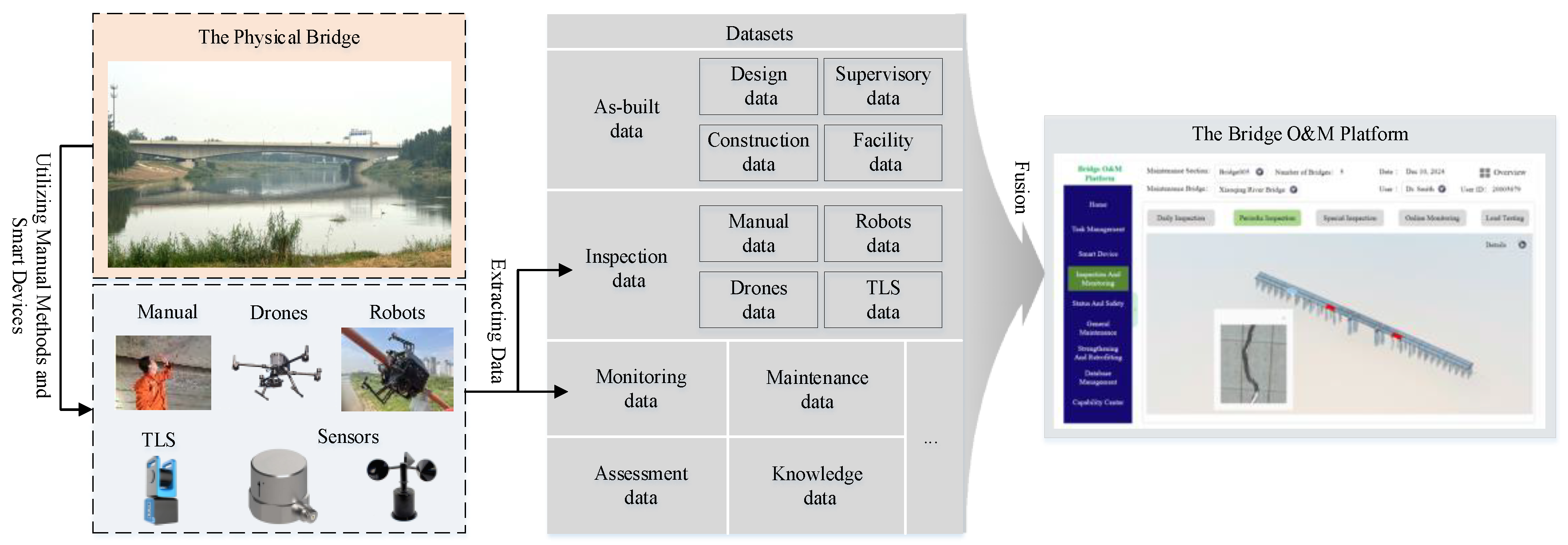
Figure 2.
The framework of the workflow for bridge O&M.
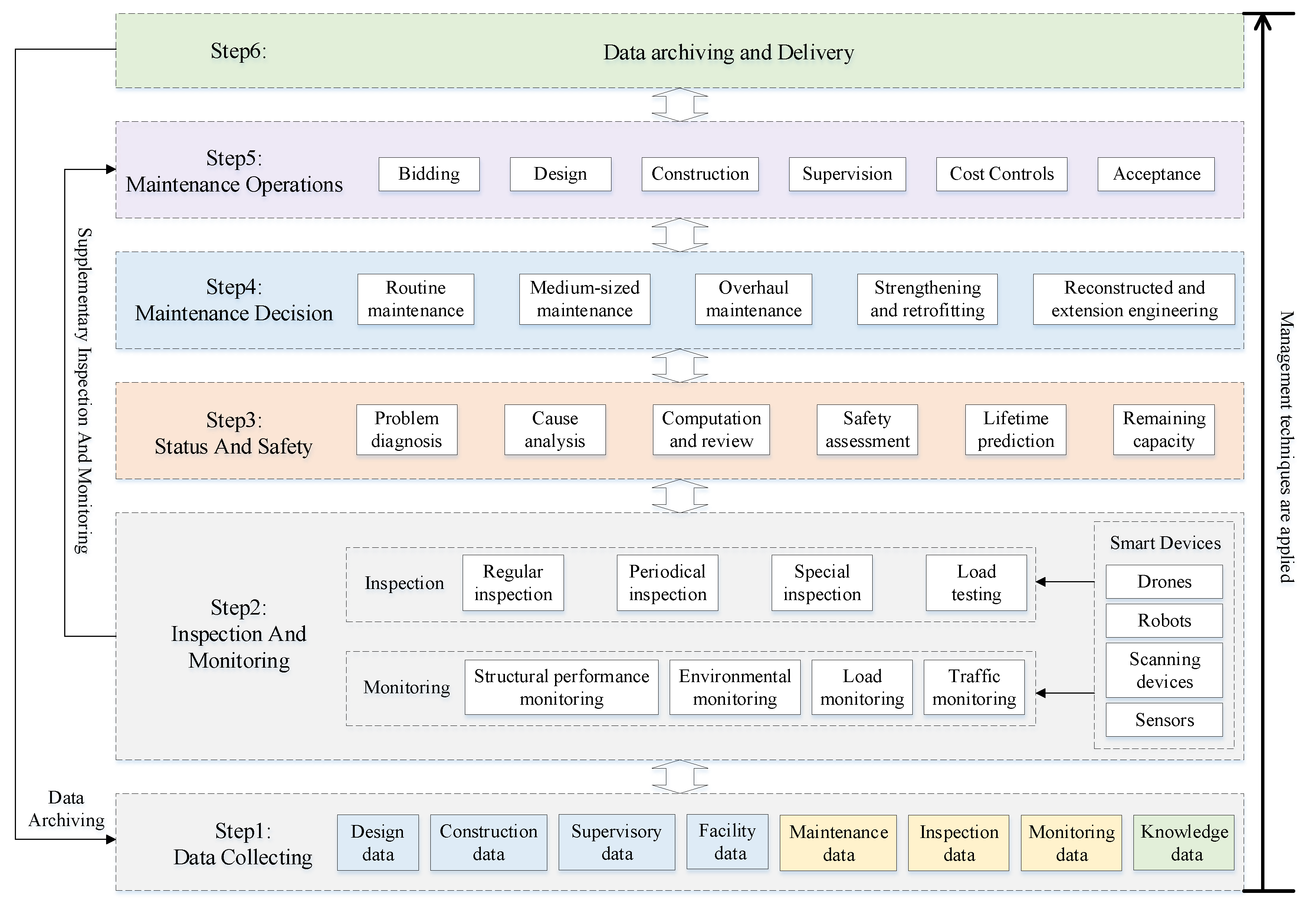
Figure 3.
The three-layer architecture for the bridge O&M platform.
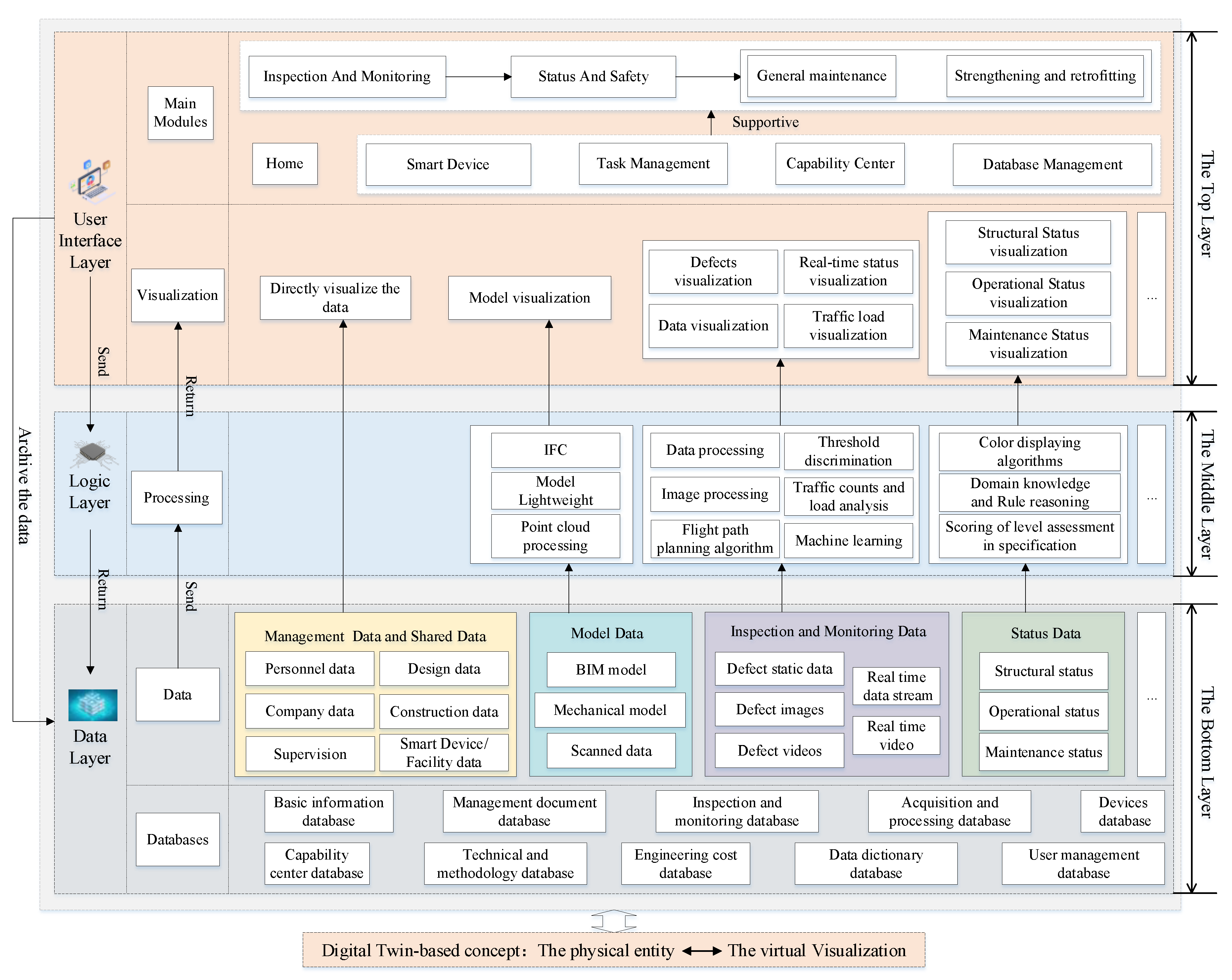
Figure 4.
The details of the front-end interface.
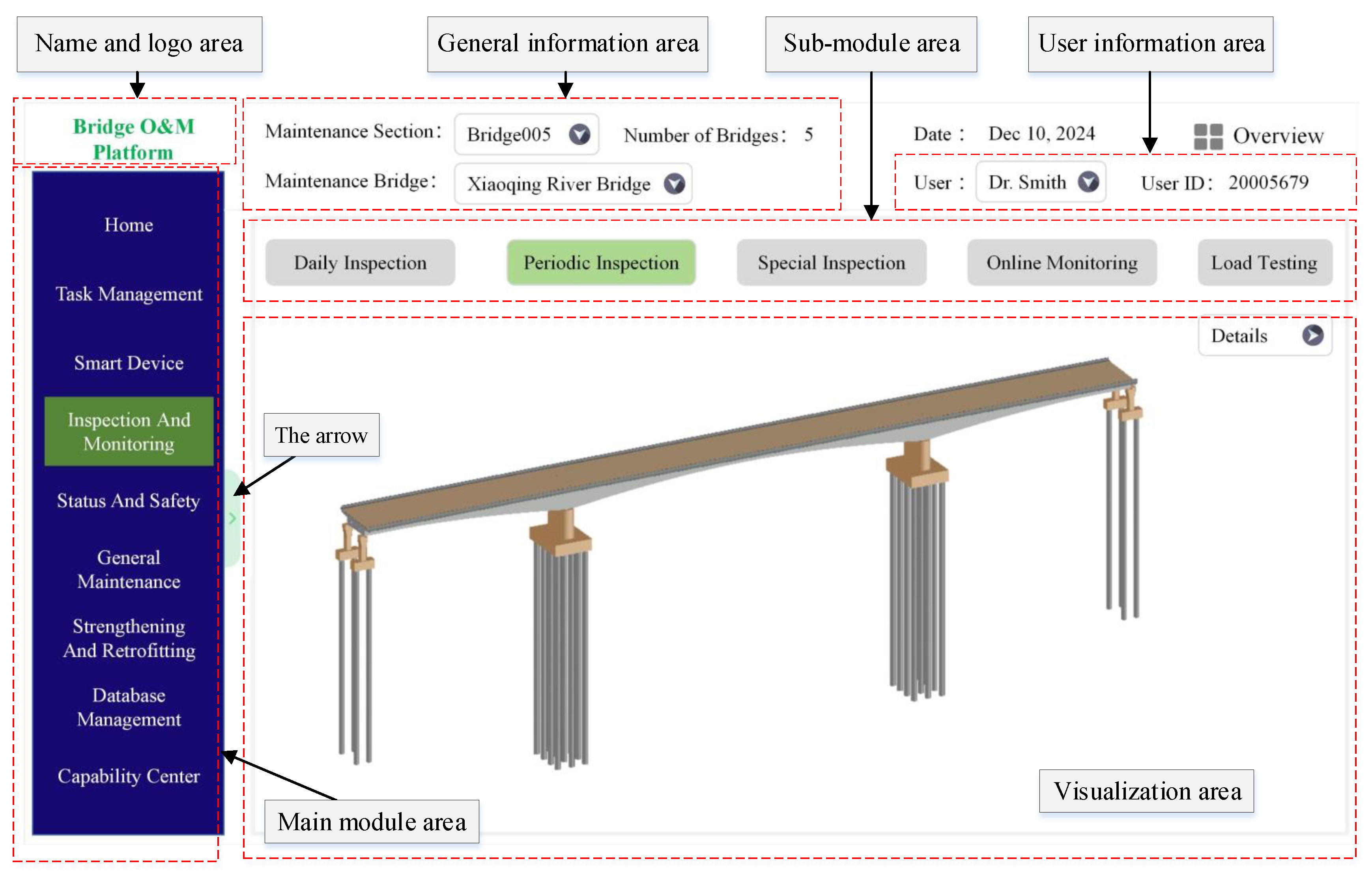
Figure 5.
A sample of the hierarchical architecture for the platform module.
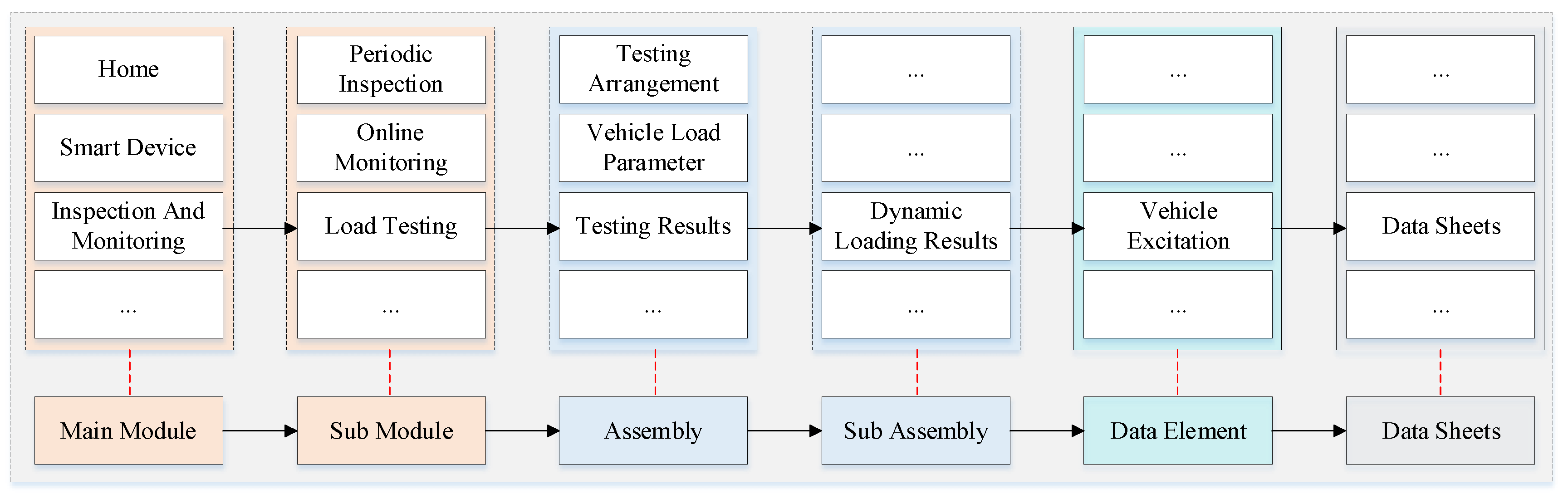
Figure 6.
The organizational framework of the data for the platform.
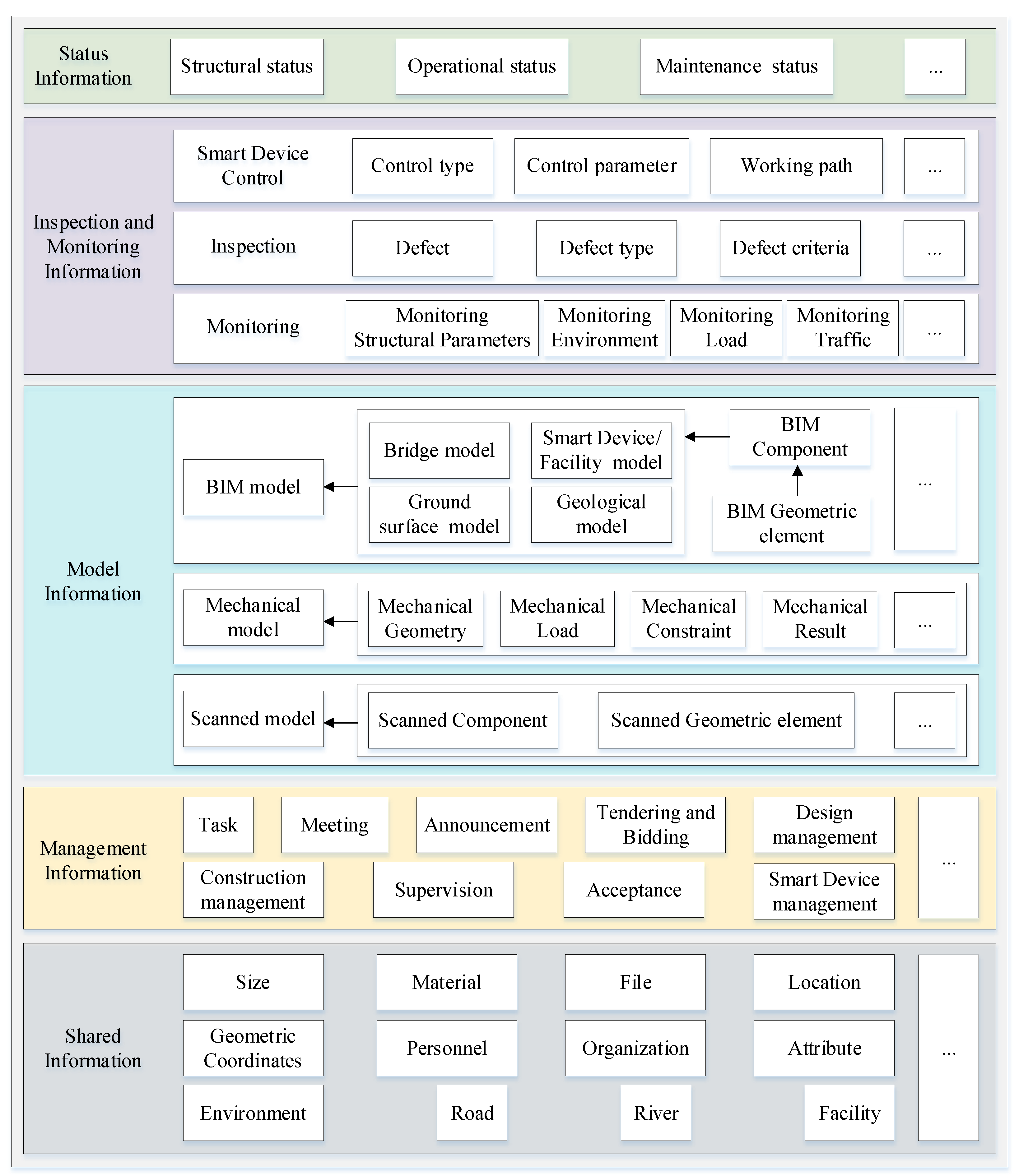
Figure 7.
The concept of metadata and meta-metadata within a data instance.
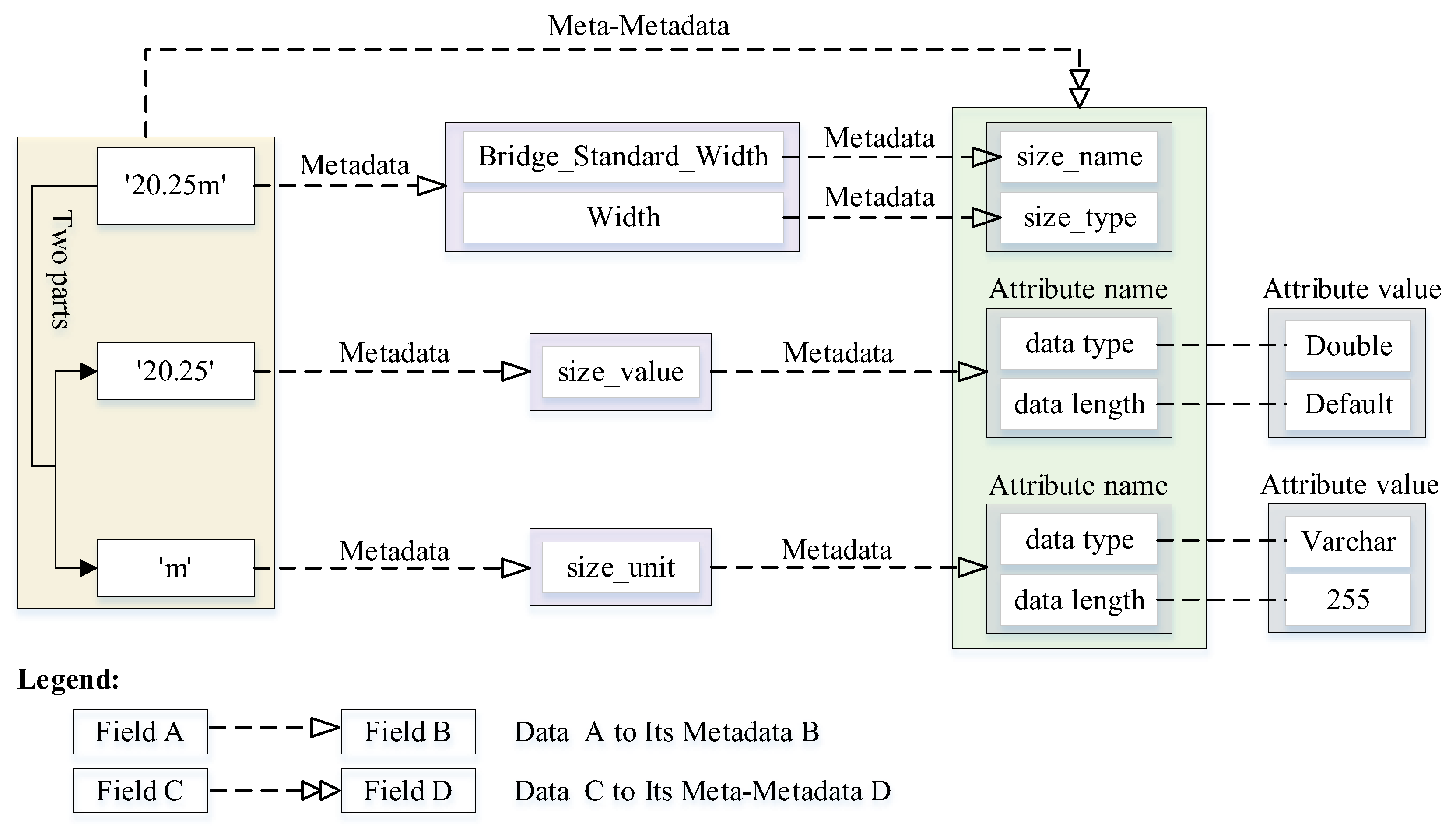
Figure 8.
The details of the data structure for the Shared Information.
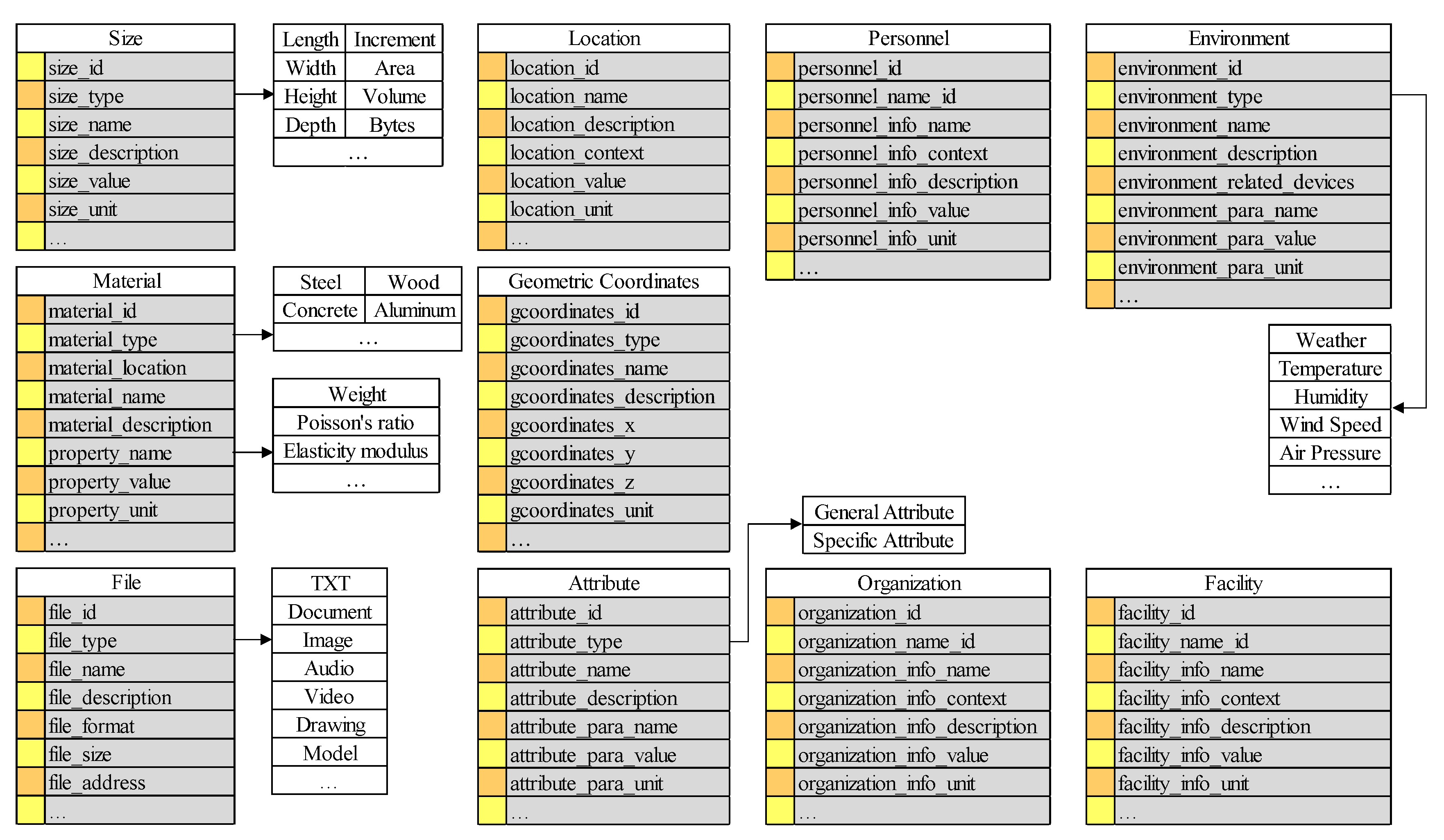
Figure 9.
The relationship between the Bridge Basic Information classification table and its sub-tables.
Figure 9.
The relationship between the Bridge Basic Information classification table and its sub-tables.
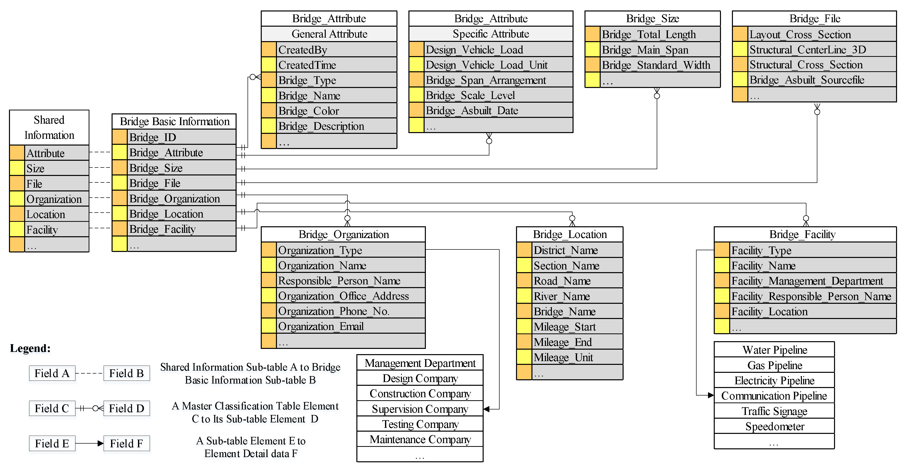
Figure 10.
The process of constructing the data structure tables for Bridge Basic Information in MySQL.
Figure 10.
The process of constructing the data structure tables for Bridge Basic Information in MySQL.
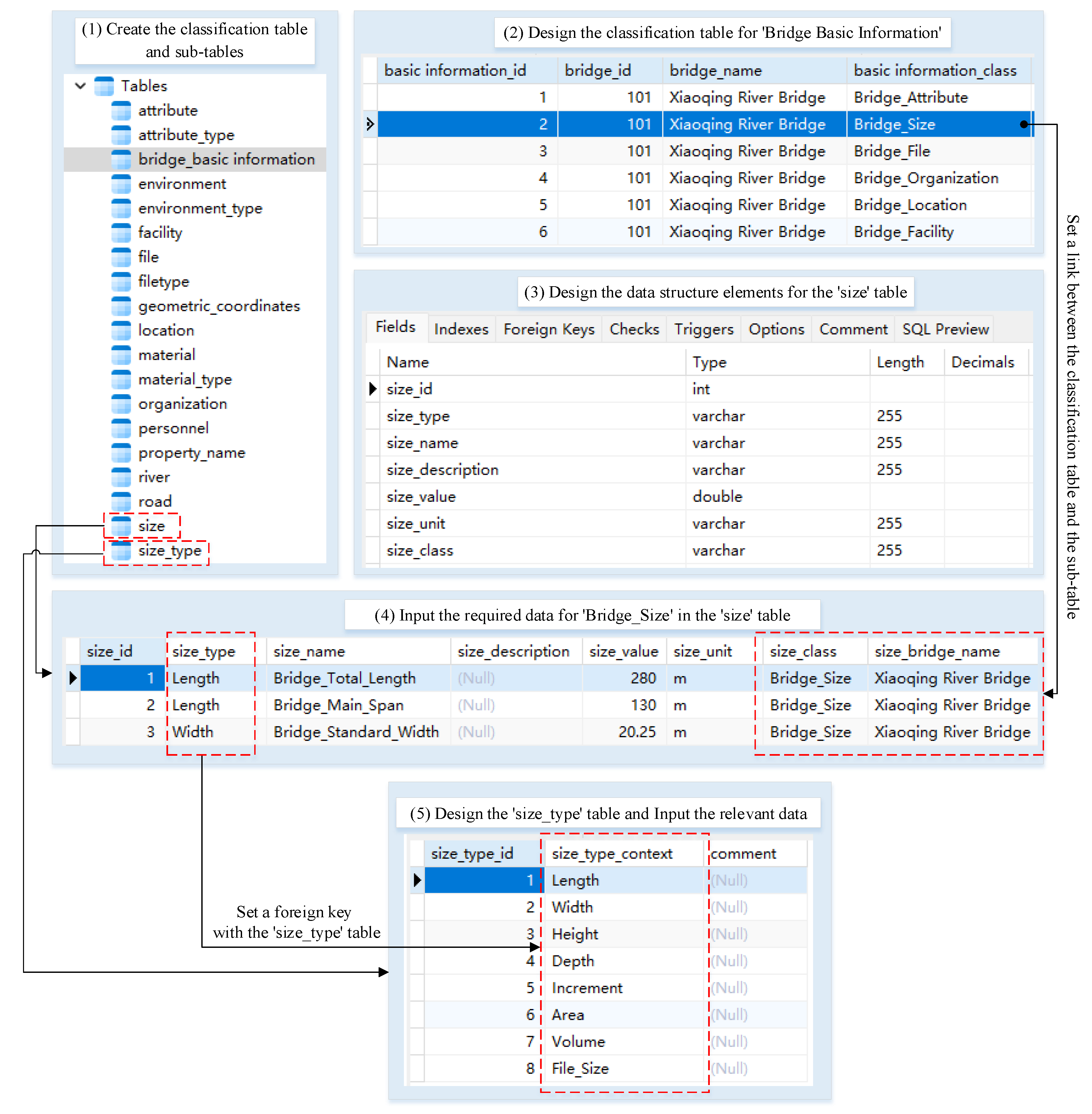
Figure 11.
The details of the Defect data structure.
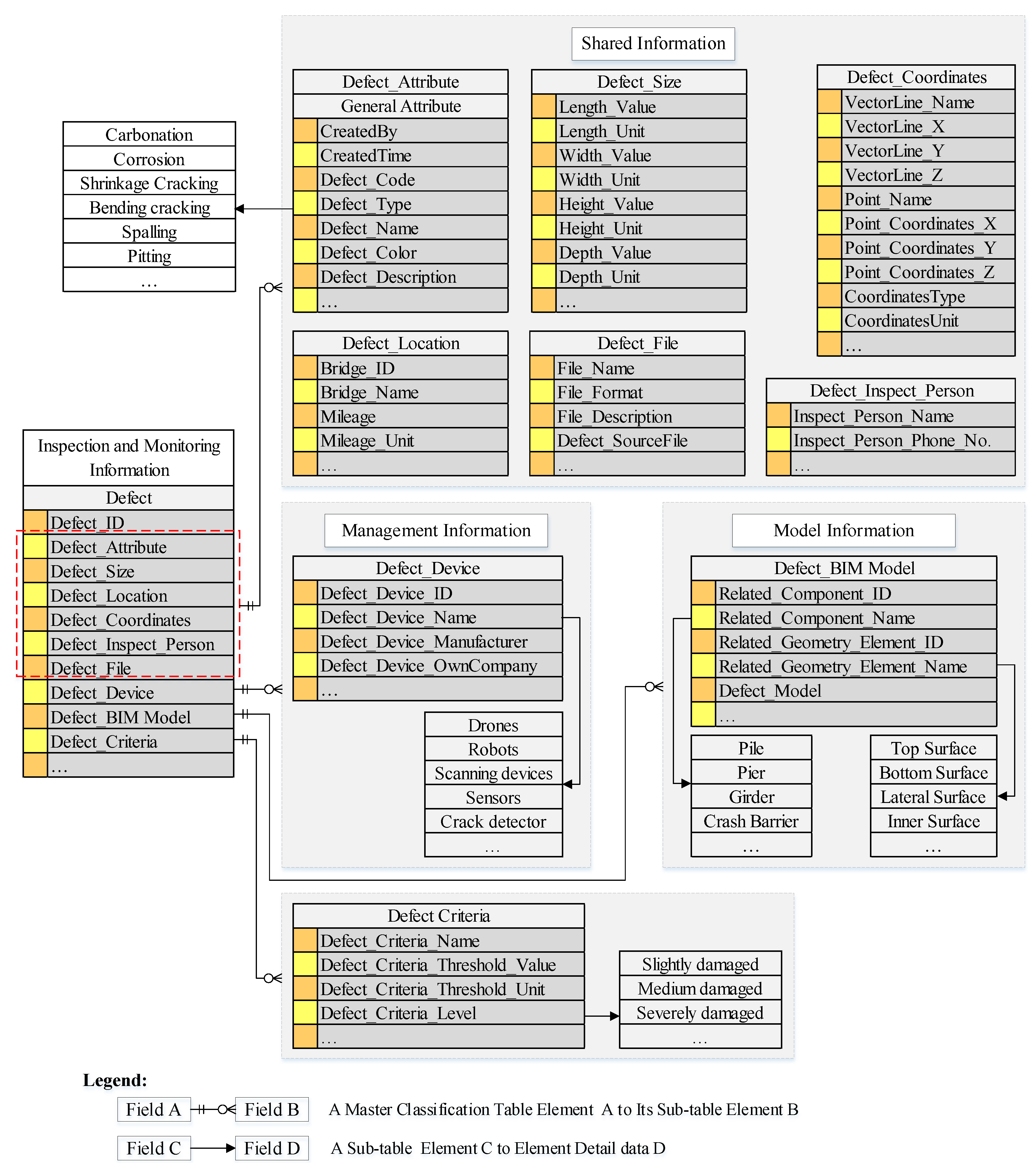
Figure 12.
The location and BIM model of the main bridge of the Xiaoqing River Bridge.
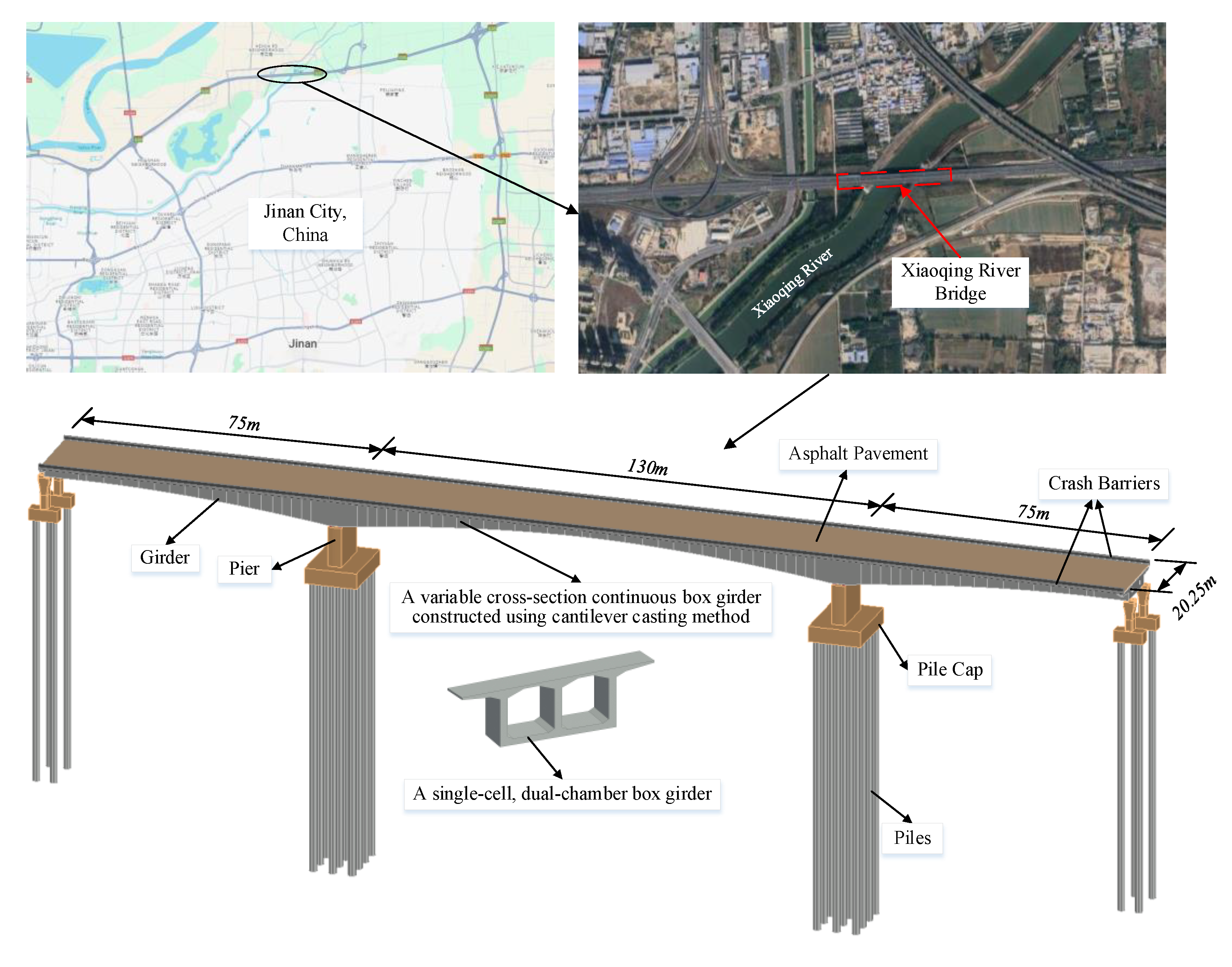
Figure 13.
Example of the presentation for the crack of Xiaoqing River Bridge.
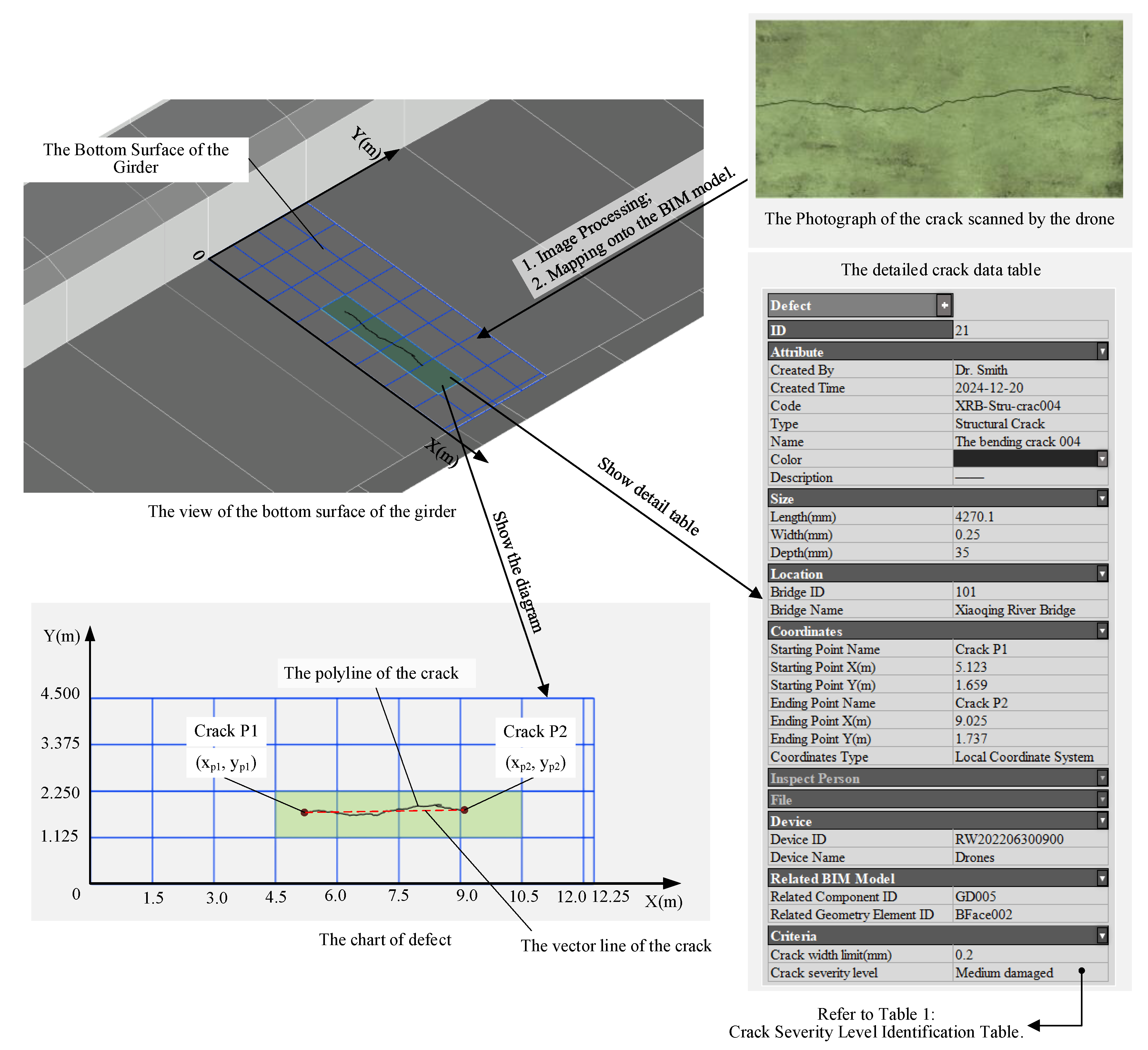

Table 1.
Crack Severity Level Identification Table.
| No. | Crack width range (mm) | Crack Length to Surface Width Ratio | Structural Crack (Yes/No) | Crack Severity Level | Recommendation | |
| 1 | < 0.2 | < 1/3 | - | Slightly damaged | No immediate action is needed, monitor periodically. | |
| 2 | 0.2 to 0.5 | 1/3 to 1/2 | Yes | Medium damaged | Inspection is required and may need repair or reinforcement. | |
| 3 | > 0.5 | >1/2 | Yes | Severely damaged | Immediate action is required, and repair or reinforcement is necessary. |
Disclaimer/Publisher’s Note: The statements, opinions and data contained in all publications are solely those of the individual author(s) and contributor(s) and not of MDPI and/or the editor(s). MDPI and/or the editor(s) disclaim responsibility for any injury to people or property resulting from any ideas, methods, instructions or products referred to in the content. |
© 2025 by the authors. Licensee MDPI, Basel, Switzerland. This article is an open access article distributed under the terms and conditions of the Creative Commons Attribution (CC BY) license (http://creativecommons.org/licenses/by/4.0/).
Copyright: This open access article is published under a Creative Commons CC BY 4.0 license, which permit the free download, distribution, and reuse, provided that the author and preprint are cited in any reuse.


