Submitted:
02 April 2025
Posted:
03 April 2025
You are already at the latest version
Abstract
The aim of this study was to investigate the effect of base material, restorative material and finish line on marginal and internal fit and fracture strength (FS) of endocrowns (N = 64). The restorative materials were ceramic and hybrid ceramic, the preparations were ferrule and modified butt joint (BJ) with two grooves, and the bases were with and without fiber ribbon. Marginal and internal fit were assessed using the triple scan. Statistical analyses were performed using three-way ANOVA. The absolute marginal discrepancy (AMD), marginal discrepancy and overall fit values obtained for ceramic were 127 µm, 108 µm and 120 µm, whereas those obtained for hybrid ceramic were 139 µm, 116 µm and 130 µm, respectively (p < 0.05). The overall FS obtained for ceramic was 662 N, whereas that for hybrid ceramic was 903 N (p < 0.001). When the material was evaluated regardless of preparation and base, ceramic and hybrid ceramic exceeded the selected clinical acceptability threshold for AMD, but did not exceed it for other parameters. Hybrid ceramic restorations with ferrules and fiber bases tended to provide the highest FS, whereas ceramic restorations with modified BJs and without fiber bases tended to provide the lowest FS.
Keywords:
endocrown
; hybrid ceramic
; fiber ribbon
; computer-aided design
; tooth preparation
; marginal fit
; triple scan
; fracture strength
1. Introduction
Long-term use of endodontically treated severely damaged teeth is difficult due to biomechanical deterioration [1]. Advances in adhesive technology have introduced minimally invasive treatments and in 1999, a type of restoration called ‘endocrown’ was introduced that does not contain an intra-canal retainer. Retention in this monolithic ceramic restoration was in particular provided by the macromechanical properties of the axial walls of the pulp chamber [2].
Fracture strength (FS) is an important factor in the biomechanical performance of restorations. The type of material and preparation and the marginal and internal fit are among the factors that influence the FS of endocrowns [3]. There are different types of preparation depending on the finish line and pulpal cavity design. Basically, there are two types of finishing lines, called butt joint (BJ) or ferrule. The BJ has a 1-2 mm wide flat enamel band that forms a 90-degree angle with the axial wall. The difference of the ferrule from the BJ is the presence of a shoulder or chamfer finish line that makes a 90° angle to the enamel band. Of the limited number of studies that have investigated the effect of the finish line on FS, some have reported that the BJ is more favorable, while others have reported that the ferrule is more favorable [4,5]. A few studies investigated modified finish lines. In one study with a BJ [6], the finish line placement was at different level with respect to the cementoenamel junction (CEJ), while in another study [7], a finish line was prepared with axial walls of partially different depth. It appears that conducting new investigations examining the effect of finish line designs on FS is of critical importance.
There are a number of studies that have investigated the effect of the design of the pulp chamber on the FS of endocrowns. One study reported low FS of all endocrowns regardless of pulp chamber depth [8], while another study [9] reported higher FS of endocrowns with deep compared to shallow pulp chambers. While there have been studies [10,11] reporting that deep recesses at the base of the pulp chamber increase FS, there have also been studies [12,13] reporting that the remaining tooth tissue or normal anatomy of the pulp chamber walls should be preserved.
Resin-containing materials are usually used as pulp base materials [10]. In one study [14], it was reported that the use of fiber in the base material could change the crack propagation from irreparable to repairable, whereas in another study [15], fiber did not significantly affect both FS and pattern. Based on the results of previous studies, it is understood that comprehensive studies including modified preparation designs should be carried out.
On the other hand, studies that examined the effect of marginal or internal fit on FS focused on the finish line, restorative material or pulpal design [11,16,17]. In some previous studies, the marginal fit was analyzed using two reference points called marginal discrepancy (MD) and absolute marginal discrepancy (AMD) [18,19]. Holmes et al. [20] defined the MD as the perpendicular measurement from the cervical edge of the crown to the edge of the preparation and the AMD as the angular combination of the MD and the extension error (over-extension or under-extension). The increase in MD leads to an increase in microleakage and consequently an increase in the amount of cement material exposed to the oral environment and dissolved. AMD is an indicator of indentation or protrusion of the crown margin relative to the finish line and is important because it increases plaque accumulation [21]. MD and AMD parameters were used in the few studies in which the marginal and internal fit of computer-aided design/computer-aided manufacturing (CAD/CAM) fabricated restorations were evaluated by triple scan.
For these reasons, the aim of this study was to investigate the effect of restorative material, preparation or base material type on FS and marginal and internal fit in endocrowns. The first null hypothesis was that material, preparation and base type would not affect marginal and internal fit and the second null hypothesis was that they would not affect FS.
2. Materials and Methods
Ethical approval was obtained from XXX prior to the start of the study (file number). The process was divided into six stages as (1) tooth selection and endodontic treatment, (2) base and tooth preparation, (3) restoration production and fit measurements, (4) permanent cementation, (5) thermomechanical aging and FS testing, (6) stereomicroscopic assessment, and each stage was performed by different people for standardization and randomization.
Sample size was determined using a power analysis program (G-Power ver. 3.1.9.7; Heinrich-Heine-Universität, Düsseldorf, Germany). With a significance level (alpha) of 0.05, a power of 0.80 and an effect size of 0.40, the minimum sample size was set at 52. The sample size was set at 64 to prevent losses from reducing the power of the study [22].
Mandibular first molars newly extracted for periodontal reasons were collected for this study. The crown and root dimensions of the teeth were measured using a digital caliper (Caliper; Yamer Industry, İzmir, Turkey) and teeth with similar dimensions were included in the study. Other inclusion criteria were absence of caries, absence of visible cracks, absence of restoration or root canal treatment, and complete root formation. The teeth were stored in 0.1% thymol solution at 4°C for disinfection immediately after extraction until the start of the study. The materials used in the study are listed in Table 1.
Two main groups were formed according to the type of restorative material (n = 32). The groups were divided into two groups according to the type of preparation (n = 16). These groups were also divided into two groups according to the type of base (n = 8). Teeth were randomly selected for the groups (Figure 1).
The teeth were cut horizontally 2 mm above the CEJ using a water-cooled separator (IsoMet 5000; Buehler, IL, USA). Root canals were prepared with a 10 K file (K- File; Dentsply-Maillefer, Ballaigues, Switzerland). Chemomechanical root canal preparation was performed with a rotating file system (Protaper; Dentsply-Maillefer, Ballaigues, Switzerland). A 5.25% sodium hypochlorite solution (Calasept; Nordiska Dental, Angelholm, Sweden) was used for irrigation. The canals were filled with gutta-percha (Protaper Next; Sirona Dental, Behnsheim, Germany) using the lateral condensation method.
All tooth preparations were performed with the same set of diamond burs (Dental Burs; B&D Technologies, Guangzhou, China). Depth and width measurements were made with a periodontal probe to ensure standardization.
The axial walls of the pulp chamber were corrected with a round end cylinder diamond bur (1.4ø/6.0L). The axial bevel was standardized to 8-10° using a double-cone diamond bur (3.5ø/6.0L).23 The depth was set at 3.6 mm.
The pulp chamber walls were etched with 37% phosphoric acid (Ultra-etch; Ultradent, UT, USA). After a waiting period of 15 s, it was washed and air dried and a bonding agent (G-Premio Bond; GC Dental, Tokyo, Japan) was applied. After a waiting period of 10 s, it was cured for 20 s with an LED light source (Elipar S10; 3M ESPE, Seefeld, Germany).
In the group without fiber ribbon, a flowable resin (G-aenial Universal Injectable; GC Corp, Tokyo Japan) was applied to the base and cured for 20 s. In the group with fiber ribbon, a thin layer of flowable resin (G-aenial Universal Injectable; GC Corp, Tokyo Japan) was applied to the cavity (0.5 mm thick), the cut and sized fiber ribbon was inserted into the resin in two layers (0.1 mm thick), a second layer of flowable resin (0.5 mm thick) (G-aenial Universal Injectable; GC Corp, Tokyo, Japan) was applied on top of the fiber ribbon and cured for 20 s. The design and preparation of the base with fiber ribbon is shown in Figure 2a and Figure 3. The teeth were kept in distilled water at 4°C for one day for standardization.
In this study, pulpal depth was prepared at 2.5 mm, taking into account the conclusion that deep pulpal cavities reduce FS in previous studies comparing 2.5 mm and 5 mm [3], 2 mm and 4 mm [8], 1 mm and 5 mm [10].
The enamel band was prepared to be at least 2 mm wide. Retention grooves with a depth of 1.0 mm and a length of 2.5 mm parallel to the long axis of the tooth were made at the mesiobuccal and distolingual corners using a cylindrical diamond bur (1.2ø/8.0L) with a round end. The final tooth preparation with the modified BJ is shown in Figure 2b and 2c. Ferrule finish line had two differences from the other: Firstly, no retention grooves were created in the pulpal region. Secondly, a ferrule design was formed on the enamel band. A flat end cylinder diamond bur (1.0ø/4.0) was used for this purpose. The ferrule was set as a 2 mm high, 1 mm wide shoulder. The prepared teeth were immersed in distilled water at 4°C for one day for standardization.
The restorative materials used in this study were manufactured using a CAD/CAM system. One of them is feldspathic (Cerec Blocs; Sirona Dental, Beinsheim, Germany [CE]) and the other one is hybrid ceramic (Cerasmart 270; GC Corp, Tokyo, Japan [CS]).
The prepared teeth were scanned using an intraoral scanner (Cerec Omnicam 4.5; Sirona Dental, Bensheim, Germany). The 'Comply with instrument geometry' button was disabled. The 'Distance' button was used to standardize the cervicoocclusal lengths to 7 mm [24]. To avoid differences between the groups, the pulpal and axial cement spacing was set to 80 µm. The crowns were fabricated on a milling machine (Cerec MC XL; Sirona Dental, Bensheim, Germany) and polished with an appropriate polishing kit (EVE Flexi-Dia Ra; EVE Ernst Vetter, Keltern, Germany).
The triple scan was performed with the same intraoral scanner. Teeth were scanned in the "Lower jaw" tab, endocrowns in the "Upper jaw" tab, and teeth with endocrowns in the "Buccal" tab. The buccal tab with a green tick was moved towards the “Biocopy sub” tab. The generated scan files were imported into another program (Exocad DentalCAD; Exocad, Darmstadt, Germany) to evaluate the marginal and internal fit.
For standardization, the teeth were kept in distilled water at 4°C for 1 day and then permanent cementation was started. The inner surfaces of the restorations were etched with 5% hydrofloic acid (IPS Ceramic Etching Gel; Ivoclar Vivadent, Schaan, Liechtenstein) for 60 s and then silane (Ceramic Primer II; GC Corp, Tokyo, Japan) was applied. The teeth were etched with 37% phosphoric acid (Ultra-etch; Ultradent, UT, USA) for 15 s. A bonding agent (G-Premio Bond; GC Corp, Tokyo, Japan) was applied and cured for 20 s with an LED light source (Elipar S10; 3M ESPE, Seefeld, Germany). The restorations were cured with an adhesive resin (G-CEM One; GC Corp, Tokyo, Japan) using the same light source under finger pressure for 60 s [25]. After a curing time of 20 s on each surface, the teeth were kept in distilled water at 4 °C until the thermomechanical aging was performed.
The triple scan files were opened in the software (Exocad DentalCAD; Exocad, Darmstadt, Germany) in the order lower, upper and buccal. The mesiodistal and buccolingual sections of the teeth were visualized using the 'Regional view' button. The mesiodistal and buccolingual sections were determined using the center of the central fossa of the teeth as a guide.
Marginal and internal fit measurements were performed using the “Distance” tab. It had been reported that the accuracy would increase as the number of measurement points increased. Therefore, a total of 12 measurements were taken in the buccolingual section, including AMD, MD, axial and pulpal. In the mesiodistal section, 12 measurements were taken in the same way [26]. The reference points for marginal and internal fit are shown in Figure 2d and 2e.
Thermomechanical cyclic loading was performed using a thermocycler (SD Mechatronik Thermocycler; Julabo, Seelbach, Germany). The specimens were subjected to 10000 cycles in 5°C and 55°C water with a dwell time of 30 s to mimic 1 year of wear [27]. After thermomechanical aging, the specimens were stored in distilled water at 4°C until fracture testing was performed.
A load application angle of 45° was chosen to mimic a scenario where the force is concentrated in the cervical region [28]. The tip of the fracture tester (Lloyd Lrx; Lloyd Instruments, Bognor Regis, UK) with a 5 mm diameter steel ball was placed at an angle of 45° at the level of the central fossa of the teeth, at the beginning of the occlusolingual slopes of the buccal tubercles (Figure 2f) [24]. The fracture test was started with a force of 50 N at a cross-head speed of 1.0 mm/min. The value of the force at fracture was recorded in Newton (N).
Specimens were examined under a stereomicroscope (Leica MZ12; Leica Microsystems, Heerbrugg, Switzerland) at 8x magnification. Failure types were categorized as follows: Type 1; cohesive failure in endocrown, Type 2; adhesive failure between endocrown and dentin, Type 3; cohesive failure in enamel/dentin, Type IV; fracture extending towards the root, above the CEJ, Type V; fracture extending below the CEJ (irreparable) [29].
Statistical analysis was performed using a software package (SPSS Statistics 30.0; IBM Corp, NY, USA). Descriptive statistics, including mean and standard deviation, were calculated for each group. The Kolmogorov-Smirnov test was used to test whether the distribution of each variable was normally distributed. Three-way analyses of variance (ANOVA) was performed to assess the interaction between the three independent variables, material, preparation and base, and the main effects of each variable on marginal and internal fit and FS. Statistical significance was set at p < 0.05.
3. Results
This section may be divided by subheadings. It should provide a concise and precise description of the experimental results, their interpretation, as well as the experimental conclusions that can be drawn.
According to the ANOVA results of the marginal and internal fit, the effect of the material variable on AMD, MD, axial, pulpal and overall fit was statistically significant (p < 0.05) (Table 2).
When the material was analyzed regardless of preparation and base, the AMD, MD, axial, pulpal and overall fit values obtained for CE were 127 ± 23 µm, 108 ± 9 µm, 106 ± 9 µm, 139 ± 29 µm and 120 ± 6 µm, respectively, while for CS were 139 ± 23 µm, 116 ± 13 µm, 112 ± 10 µm, 151 ± 20 µm and 130 ± 11 µm (p < 0.05) (Table 3).
When the preparation was analyzed regardless of material and base, the AMD, MD, axial, pulpal and overall fit values obtained for modified BJ were 135 ± 20 µm, 113 ± 9 µm, 107 ± 9 µm, 141 ± 25 µm and 124 ± 10 µm, respectively, while for ferrule were 131 ± 27 µm, 112 ± 13 µm, 111 ± 10 µm, 149 ± 26 µm and 126 ± 10 µm (p > 0.05).
When the base was analyzed regardless of preparation and material, the AMD, MD, axial, pulpal and overall fit values obtained for ES were 133 ± 23 µm, 111 ± 11 µm, 110 ± 11 µm, 152 ± 23 µm and 126 ± 9 µm, respectively, while for GU were 134 ± 25 µm, 113 ± 12 µm, 109 ± 9 µm, 138 ± 27 µm and 123 ± 11 µm (p > 0.05).
Figure 4 shows the mesiodistal section in the tooth with modified BJ, the buccolingual section in the tooth with ferrule, fiber ribbon and CS, the mesial MD measurement in the tooth with ferrule, fiber ribbon and CE, and the buccal MD measurement in the tooth with ferrule, without fiber base and with CS.
According to the ANOVA results of the FS, the effect of material, preparation, base and preparation-base on FS was statistically significant (p < 0.05) (Table 2).
When the material was analyzed regardless of preparation and base, the FS obtained for CE was 662 ± 209 N, while for CS was 903 ± 238 N (p < 0.001). When preparation was analyzed regardless of material and base, the FS obtained for modified BJ was 660 ± 199 N, while for ferrule was 905 ± 245 N (p < 0.001). When base was analyzed regardless of material and preparation, the FS obtained for ES was 935 ± 236 N, while for GU was 630 ± 163 N (p < 0.001) (Table 3).
The results of the pairwise interactions are shown in Table 4. When material-preparation was analyzed regardless of base, the FS was CS-ferrule (1035 ± 218 N), CE-ferrule (774 ± 201 N), CS-modified BJ (772 ± 182 N), CE-modified BJ (549 ± 150 N), respectively (p > 0.05). When material-base was analyzed regardless of preparation, the FS was CS-ES (1075 ± 185 N), CE-ES (796 ± 200 N), CS-GU (732 ± 144 N), CE-GU (528 ± 109 N), respectively (p > 0.05). When preparation-base was analyzed regardless of material, the FS was ferrule-ES (1084 ± 180 N), modified BJ-ES (787± 190 N), ferrule-GU (725 ± 153 N), modified BJ-GU (534 ± 109 N), respectively (p = 0.044).
Failure types are shown in Figure 5. According to the results, the failure types were Type V (22 teeth; 34%), Type IV (16 teeth; 25%), Type III (12 teeth; 19%), Type II (13 teeth; 20%) and Type I (1 tooth; 2%).
Figure 6 shows images of teeth with ferrule, fiber ribbon and CE, teeth with modified BJ, fiber ribbon and CE, teeth with CS and without fiber ribbon after FS test.
4. Discussion
In this study, the null hypotheses that material, preparation or base would not affect the marginal and internal fit and FS of endocrowns were partially rejected. Based on previous studies [21,23,30,31,32], threshold values were chosen as 120 µm for AMD, MD, axial and overall fit and 160 µm for pulpal fit. According to the results of this study, when material was analyzed regardless of preparation and base, the AMD, MD, pulpal, axial and overall fit values obtained for CS were statistically significantly higher than CE. The MD values of both materials did not exceed the threshold, but the AMD values were higher than the threshold (up to 19 µm for CS and 7 µm for CE). Small differences are reported to be clinically insignificant [30]. Therefore, the values obtained for both materials can be considered clinically appropriate. The pulpal and axial fit values of CS were 151 ± 20 µm and 112 ± 10 µm, respectively, whereas those of CE were 139 ± 29 µm and 106 ± 9 µm.
In this study, digital measurements were taken using Omnicam (Sirona Dental, Behnsheim, Germany), similar to previous studies [30,33]. In the study by de Paula Siveria et al. [30], the fit results obtained for ceramics were in the order of pulpal > AMD > MD, similar to this study, but the values were found to change when the device was changed. de Fayed et al. [33] reported that the cement spacing should be 80 µm to achieve good FS. Dauti et al. [34] reported that restorations with uniform cement thickness would have better biomechanical behavior. In accordance with the above studies, the pulpal and axial cement spacing in this study was equal and 80 µm.
In this study, although the teeth were prepared according to the basic preparation rules, the presence of undesirable defects such as sharp corners and edges and undercuts may have adversely affected the fit of the restorations. In addition, the restorations placed on the teeth may have moved unnoticed during the triple scan. Svanborg et al. [35], in a study comparing the silicone replica and triple scan methods, reported that if pressure had been applied during the triple scan, fit values lower than the current values could have been obtained. Another factor that may cause measured values to differ from calculated values has been reported to be the knowledge and skill of the personnel using the CAD/CAM device [23].
Consistent with previous studies [26,36], pulpal fit values in this study were higher than axial fit and MD values. The differences in axial and pulpal fit may be due to a phenomenon that causes distortion when the burs capture the pulpoaxial angles [30]. Dahl et al. [37] stated that it would be logical to believe that this is due to the size and shape of the burs being incompatible with the internal corners. Taha et al. [4] reported that the more complex the preparation design, the more the fit between the endocrown and the hollow surface of the tooth would deteriorate.
The triple scan method, which is becoming increasingly popular, was the method of choice in this study due to its good reproducibility, reliability and ability to provide a comprehensive three-dimensional examination. It has been reported that the more points analyzed, the more accurate the results [38]. Contrepois et al. [39] stated that the total number of measurement points should be at least 18. Therefore, in this study, a method was designed in which a total of 24 measurements were taken on one tooth.
As the abrasion ability of the burs is higher in materials with low hardness and elastic modulus, the risk of discrepancy between tooth and restoration may be increased [23]. The first material used in this study was a feldspathic ceramic with an elastic modulus of 45 GPa and a Vickers hardness of 640 HV. The other material is a hybrid ceramic containing 29% resin matrix and 71% filler with elastic modulus of 9.6 GPa and Vickers hardness of 89 HV [40]. These materials were industrially produced and could be applied to the mouth immediately after milling. Furthermore, the milling process is performed with a program that takes into consideration the physical properties of the materials [41]. Probably for this reason, no major difference was found between the materials in terms of marginal and internal fit.
It has been reported that the occlusal force occurring in the molar region was 222-445 N (mean 322.5 N) and this value increased up to 520-800 N (660 N) during tooth clenching [42]. According to the results obtained in this study, CS (903 ± 238 N) had statistically significantly higher FS than CE (662 ± 209 N) when the material was analyzed regardless of preparation and base, ferrule (905 ± 245 N) had higher FS than modified BJ (660 ± 199 N) when the preparation was analyzed regardless of material and base, ES (935 ± 236 N) had higher FS than GU (630 ± 163 N) when the base was analyzed regardless of preparation and material.
When the triple interactions were analyzed, the FS tended to be CS-ferrule-ES, CE-ferrule-ES, CS-modified BJ-ES, CS-ferrule-GU, CE-modified BJ-ES, CS-modified BJ-GU, CE-ferrule-GU, CE-modified BJ-GU, from higher to lower. When ES was used, CS with modified BJ had higher strength than CS with ferrule, suggesting that ES should be preferred as the base material in the preparation with modified BJ. When GU was used, CSs with modified BJ had higher strength than CEs with ferrule, indicating that the modified BJ design was preferable for hybrid ceramics compared to ceramics.
In this study, in agreement with previous studies [17,43], not only was the FS of CS higher than that of CE, but the number of repairable failure types was also higher than that of CE. Feldspathic ceramics are more brittle than hybrid ceramics and the main disadvantage of brittle materials is their low fracture toughness. In the study by Dikici et al. [43] for CS and FC, Type I was the dominant failure type. Although Type I was found in only one tooth in this study, the ratio of repairable to irreparable failure types was almost 2:1. When the elastic modulus of materials is similar to those of dentin, their flexible behavior and energy dissipation properties are enhanced [44]. Compared to CE, the elastic modulus of CS is closer to dentin. Furthermore, the higher flexural strength of CS compared to CE (246 MPa for CS and 113 MPa for CE) is another factor that provides better FS [17,43]. In general, ceramics fracture according to Griffith's theory, which explains the propagation of internal cracks and the fracture initiation mechanism [27]. CS is more in accordance with the Dugdale cracking theory as it contains resin matrix and the first cracks formed give the mass the beginning of plasticity. As the load increases, plasticity the spreads and crack resistance increases along the long crack [45].
On the other hand, in a study evaluating endocrowns with CS, Zheng et al. [44] reported that keeping the crown margin high would increase FS. However, healthy tissue may not be available to maintain the crown margin elevated at all times. Ghoul et al. [29] analyzed a BJ design with two grooves, similar to the present study, but horizontal and axial forces were applied instead of oblique forces, and the grooves were reported to increase FS. As similar results were obtained in the present study, it appears that the preparation of a BJ with two grooves may be an alternative to keeping the crown margin high.
In this study, a portion of bases with flowable resin was modified with fiber ribbon. This ribbon consists of silanised, bidirectional glass fibers and a resin matrix containing bisphenol A-glycidyl methacrylate (Bis-GMA) and polymethyl methacrylate (PMMA). The material is in the form of a 0.05 mm thick sheet and is applied by cutting [14]. In this study, in agreement with previous studies [46,47] in which the base was reinforced with fiber ribbon, FS was found to be increased in restorations with fiber ribbon, and the number of teeth with irreparable failure types was decreased.
In this study, fiber ribbon consisting of bidirectional glass fiber ribbons was cut, arranged and embedded in two layers of flowable resin composite. Another study [47] using a similar technique and a different brand of fiber ribbon (Ribbond; Ribbond Inc, Seattle, USA) found, similar to this study, a decrease in the rate of irreparable fractures and an increase in Type III fractures.
Similar to this study, Anton Y Otero et al. [14] used the same hybrid ceramic material and two different base materials. One of them was a flowable resin composite (Everx Flow; GC Corp, Tokyo, Japan) containing multidirectional glass fibers, and the other was everStick NET. EverX Flow contains Bis-GMA, triethylene glycol dimethacrylate (TEGDMA), PMMA, silanated short glass fibers and barium glass fillers. In the study, it was reported that the base with three layers of fiber strips increased the FS, which was enabled by the bidirectional fiber ribbon structure of everStick NET, and that the fiber material also served to deflect the crack direction [14].
The improving effect on the FS and failure type of the fiber ribbon can be explained by the Krenchel factor. Since ES has bidirectional fiber orientation (Krenchel factor: 0.5), the efficiency of the fibers is high [48]. The position of the fiber ribbon in the composite layer can also influence the FS. Unwanted defects that occur during the correction of the base can cause the ribbon to be carried upwards and as a result the FS can be positively or negatively affected [49]. In this study, the distance between the margin of the crown and the base surface was regularly checked with a periodontal probe for standardization.
In this study, the ferrule statistically significantly increased the FS of the materials compared to the modified BJ. Einhorn et al. [5], similar to this study, found higher FS in teeth with ferrules compared to teeth with BJs, but 1 mm height in ferrules was more favorable than 2 mm. Abduljawad and Rayyan [50] reported that ferrules of 2 mm height resulted in limited dentin tissue at the preparation margin. If there is weak dentin tissue in the root, the possibility of fracture progressing to the root is strengthened. Therefore, if a ferrule preparation is designed, care should be taken to maintain a 2 mm band of intact dentin [5]. In this study, when the results were analyzed regardless of the material, statistically significantly higher FS was found in teeth with ES base and modified BJ compared to teeth with GU base and ferrule. This result indicates that modified BJ can be preferred in cases that prevent ferrule application, such as insufficient remaining intact dentin tissue, if a base with fiber ribbon is prepared.
The effect of cementation on marginal and internal fit and FS was not analyzed in this study because it was not desirable to extend the study to a dimension that would deviate from its focus, including the fit assessment. Furthermore, it may also be necessary to evaluate materials with different manufacturing and preparation methods. Another limitation was that the effect of intraoral conditions on the internal and marginal fit of restorations was not investigated. Future studies are needed to investigate the effect on marginal and internal fit and FS of endocrowns of different restorative materials and types of base and finish lines.
5. Conclusions
The results obtained within the limitations of this study are as follows:
1. When the material was analyzed regardless of preparation and base, hybrid ceramics had higher AMD, MD, axial, pulpal and overall fit values than ceramics, and the fracture strength of teeth with hybrid ceramics was higher than that of teeth with ceramics.
2. When the preparation was analyzed regardless of the base and material, the AMD, MD, axial, pulpal and overall fit values of teeth with ferrules and modified butt joints were similar, and the fracture strength of teeth with ferrules was higher than that of teeth with modified butt joints.
3. When the base was analyzed regardless of preparation and material, the AMD, MD, axial and overall fit values of the teeth with fiber and without fiber base were similar, but the pulpal fit of the teeth with fiber base was slightly higher than that of the teeth without fiber. The fracture strength of the teeth with fiber base was also higher than that of the teeth without fiber base.
4. The fit values were, from higher to lower, pulpal, AMD, overall, MD, axial. Hybrid ceramic restorations with ferrule and fiber base tended to have the highest fracture strength, whereas ceramic restorations without fiber base and modified butt joint tended to have the lowest fracture strength.
Author Contributions
Conceptualization, K.Y.; methodology, K.Y.; software, X.X.; validation, K.Y., H.A.; formal analysis, F.G.; investigation, S.K., E.Ö.; resources, O.Ç.; data curation, Z.B., E.Ö.; writing—original draft preparation, K.Y.; writing—review and editing, H.A., F.G.; visualization, S.K., O.Ç.; supervision, S.K., O.Ç. and Z.B.; project administration, H.A., F.G.; funding acquisition, K.Y., H.A., F.G. and E.Ö. All authors have read and agreed to the published version of the manuscript.
Funding
This research received no external funding.
Institutional Review Board Statement
The research protocol was approved by the ethics committee of the XXX, with the assigned reference number YYY. All methodologies utilized in this study were strictly aligned with the applicable standards and laws.
Informed Consent Statement
Not applicable.
Data Availability Statement
Data are contained within the article.
Acknowledgments
I would like to thank, XXX for his/her efforts.
Conflicts of Interest
The authors declare no conflicts of interest.
Abbreviations
The following abbreviations are used in this manuscript:
| FS | Fracture strength |
| BJ | Butt joint |
| CEJ | Cementoenamel junction |
| LD | Linear dichroism |
| MD | Marginal discrepancy |
| AMD | Absolute marginal discrepancy |
| CAD/CAM | Computer-aided design/computer-aided manufacturing |
| CE | Cerec Blocs |
| CS | Cerasmart 270 |
| N | Newton |
| ANOVA | Analyses of variance |
| Bis-GMA | Bisphenol A-glycidyl methacrylate |
| PMMA | Polymethyl methacrylate |
| TEGDMA | Triethylene glycol dimethacrylate |
References
- Rocca, G.T.; Krejci, I. Crown and post-free adhesive restorations for endodontically treated posterior teeth: from direct composite to endocrowns. Eur. J. Esthet. Dent. 2013, 8, 156–179. [Google Scholar] [PubMed]
- Bindl, A.; Mörmann, W.H. Clinical evaluation of adhesively placed Cerec endo-crowns after 2 years--preliminary results. J. Adhes. Dent. 1999, 1, 255–265. [Google Scholar] [PubMed]
- Pedrollo Lise, D.; Van Ende, A.; De Munck, J.; Umeda Suzuki, T.Y.; Cardoso Vieira, L.C.; Van Meerbeek, B. Biomechanical behavior of endodontically treated premolars using different preparation designs and CAD/CAM materials. J. Dent. 2017, 59, 54–61. [Google Scholar] [CrossRef] [PubMed]
- Taha, D.; Spintzyk, S.; Schille, C.; Sabet, A.; Wahsh, M.; Salah, T.; Geis-Gerstorfer, J. Fracture resistance and failure modes of polymer infiltrated ceramic endocrown restorations with variations in margin design and occlusal thickness. J. Prosthodont. Res. 2018, 62, 293–297. [Google Scholar] [CrossRef]
- Einhorn, M.; DuVall, N.; Wajdowicz, M.; Brewster, J.; Roberts, H. Preparation ferrule design effect on endocrown failure resistance. J. Prosthodont. 2019, 28, e237–e242. [Google Scholar] [CrossRef]
- Tarrosh, M.Y.; Moaleem, M.M.A.; Mughals, A.I.; Houmady, R.; Zain, A.A.; Moafa, A.; Darraj, M.A.; Najmi, L.E.; Bajawi, H.A.; Mohammed, S.A.; Karobari, M.I. Evaluation of colour change, marginal adaptation, fracture strength, and failure type in maxillary and mandibular premolar zirconia endo-crowns. BMC Oral Health. 2024, 24, 970. [Google Scholar] [CrossRef]
- Jalali, S.; Jalali, H.; Kharazi Fard, M.J.; Abdolrahmani, A.; Alikhasi, M. The effect of preparation design on the fracture resistance and adaptation of the CEREC ceramic endocrowns. Clin. Exp. Dent. Res. 2023, 9, 518–525. [Google Scholar] [CrossRef]
- Hayes, A.; Duvall, N.; Wajdowicz, M.; Roberts, H. Effect of endocrown pulp chamber extension depth on molar fracture resistance. Oper. Dent. 2017, 42, 327–334. [Google Scholar] [CrossRef]
- Shin, Y.; Park, S.; Park, J.W.; Kim, K.M.; Park, Y.B.; Roh, B.D. Evaluation of the marginal and internal discrepancies of CAD-CAM endocrowns with different cavity depths: An in vitro study. J. Prosthet. Dent. 2017, 117, 109–115. [Google Scholar] [CrossRef]
- Dartora, N.R.; de Conto Ferreira, M.B.; Moris, I.C.M.; Brazão, E.H.; Spazin, A.O.; Sousa-Neto, M.D.; Silva-Sousa, Y.T.; Gomes, E.A. Effect of Intracoronal Depth of Teeth Restored with Endocrowns on Fracture Resistance: In Vitro and 3-dimensional Finite Element Analysis. J. Endod. 2018, 44, 1179–1185. [Google Scholar] [CrossRef]
- Gaintantzopoulou, M.D.; El-Damanhoury, H.M. Effect of Preparation Depth on the Marginal and Internal Adaptation of Computer-aided Design/Computer-assisted Manufacture Endocrowns. Oper. Dent. 2019, 41, 607–616. [Google Scholar] [CrossRef]
- Tribst, J.P.M.; Dal Piva, A.M.O.; Madruga, C.F.L.; Valera, M.C.; Borges, A.L.S.; Bresciani, E.; de Melo, R.M. Endocrown restorations: Influence of dental remnant and restorative material on stress distribution. Dent. Mater. 2018, 34, 1466–1473. [Google Scholar] [CrossRef]
- Zhu, J.; Wang, D.; Rong, Q.; Qian, J.; Wang, X. Effect of central retainer shape and abduction angle during preparation of teeth on dentin and cement layer stress distributions in endocrown-restored mandibular molars. Dent. Mater. J. 2020, 39, 464–470. [Google Scholar] [CrossRef] [PubMed]
- Anton Y Otero, C.; Bijelic-Donova, J.; Saratti, C.M.; Vallittu, P.K.; di Bella, E.; Krejci, I.; Rocca, G.T. The influence of FRC base and bonded CAD/CAM resin composite endocrowns on fatigue behavior of cracked endodontically-treated molars. J. Mech. Behav. Biomed. Mater. 2021, 121, 104647. [Google Scholar] [CrossRef]
- Rocca, G.T.; Saratti, C.M.; Cattani-Lorente, M.; Feilzer, A.J.; Scherrer, S.; Krejci, I. The effect of a fiber reinforced cavity configuration on load bearing capacity and failure mode of endodontically treated molars restored with CAD/CAM resin composite overlay restorations. J. Dent. 2015, 43, 1106–1115. [Google Scholar] [CrossRef]
- Saker, S.; Alqutaibi, A.Y.; Alghauli, M.A.; Hashem, D.; Borzangy, S.; Farghal, A.E.; Alnazzawi, A.A.; Ainoosah, S.; AbdElaziz, M.H. The Influence of Ferrule Design and Pulpal Extensions on the Accuracy of Fit and the Fracture Resistance of Zirconia-Reinforced Lithium Silicate Endocrowns. Materials (Basel) 2024, 17, 1411. [Google Scholar] [CrossRef] [PubMed]
- Taha, D.; Spintzyk, S.; Sabet, A.; Wahsh, M.; Salah, T. Assessment of marginal adaptation and fracture resistance of endocrown restorations utilizing different machinable blocks subjected to thermomechanical aging. J. Esthet. Restor. Dent. 2018, 30, 319–328. [Google Scholar] [CrossRef] [PubMed]
- Yang, M.S.; Kim, S.K.; Heo, S.J.; Koak, J.Y.; Park, J.M. Investigation of the marginal fit of a 3D-printed three-unit resin prosthesis with different build orientations and layer thicknesses. J. Adv. Psthodont. 2022, 14, 250–261. [Google Scholar] [CrossRef]
- Dolev, E.; Bitterman, Y.; Meirowitz, A. Comparison of marginal fit between CAD-CAM and hot-press lithium disilicate crowns. J. Prosthet. Dent. 2019, 121, 124–128. [Google Scholar] [CrossRef]
- Holmes, J.R.; Bayne, S.C.; Holland, G.A.; Sulik, W.D. Considerations in measurement of marginal fit. J. Prosthet. Dent. 1989, 62, 405–408. [Google Scholar] [CrossRef]
- Abualsaud, R.; Alalawi, H. Fit, Precision, and Trueness of 3D-Printed Zirconia Crowns Compared to Milled Counterparts. Dent. J. (Basel) 2022, 10, 215. [Google Scholar] [CrossRef] [PubMed]
- Nagi, N.; Fouda, A.M.; Bourauel, C. Comparative evaluation of internal fit and marginal gap of endocrowns using lithium disilicate and polyether ether ketone materials - an in vitro study. BMC Oral Health 2023, 23, 207. [Google Scholar] [CrossRef]
- Kassis, C.; Mehanna, C.; Khoury, P.; Tohme, H.; Cuevas-Suárez, C.E.; Bourgi, R.; Lukomska-Szymanska, M.; Hardan, L. Triple scan evaluation of internal and marginal adaptation of overlays using different restorative materials. J. Esthet. Restor. Dent. 2023, 35, 493–500. [Google Scholar] [CrossRef] [PubMed]
- Sağlam, G.; Cengiz, S.; Karacaer, Ö. Marginal adaptation and fracture strength of endocrowns manufactured with different restorative materials: SEM and mechanical evaluation. Microsc. Res. Tech. 2021, 84, 284–290. [Google Scholar] [CrossRef] [PubMed]
- Mertsöz, B.; Ongun, S.; Ulusoy, M. In-Vitro Investigation of Marginal Adaptation and Fracture Resistance of Resin Matrix Ceramic Endo-Crown Restorations. Materials (Basel) 2023, 16, 2059. [Google Scholar] [CrossRef]
- Ferrairo, B.M.; Piras, F.F.; Lima, F.F.; Honório, H.M.; Duarte, M.A.H.; Borges, A.F.S.; Rubo, J.H. Comparison of marginal adaptation and internal fit of monolithic lithium disilicate crowns produced by 4 different CAD/CAM systems. Clin. Oral Investig. 2021, 25, 2029–2036. [Google Scholar] [CrossRef]
- Alexopoulou, E.; Polychronis, G.; Konstantonis, D.; Sifakakis, I.; Zinelis, S.; Eliades, T. A study of the mechanical properties of as-received and intraorally exposed single-crystal and polycrystalline orthodontic ceramic brackets. Eur. J. Orthod. 2020, 42, 72–77. [Google Scholar] [CrossRef]
- Hassouneh, L.; Jum'ah, A.A.; Ferrari, M.; Wood, D.J. Post-fatigue fracture resistance of premolar teeth restored with endocrowns: An in vitro investigation. J. Dent. 2020, 100, 103426. [Google Scholar] [CrossRef]
- Ghoul, W.E.; Özcan, M.; Tribst, J.P.M.; Salameh, Z. Fracture resistance, failure mode and stress concentration in a modified endocrown design. Biomater. Investig. Dent. 2020, 7, 110–119. [Google Scholar] [CrossRef]
- de Paula Silveira, A.C.; Chaves, S.B.; Hilgert, L.A.; Ribeiro, A.P. Marginal and internal fit of CAD-CAM-fabricated composite resin and ceramic crowns scanned by 2 intraoral cameras. J. Prosthet. Dent. 2017, 117, 386–392. [Google Scholar] [CrossRef]
- Sanchez-Lara, A.; Hosney, S.; Lampraki, E.; Conejo, J.; Blatz, M.B.; Barmak, A.B.; Ercoli, C.; Chochlidakis, K. Evaluation of marginal and internal fit of single crowns manufactured with an analog workflow and three CAD-CAM systems: A prospective clinical study. J. Prosthodont. 2023, 32, 689–696. [Google Scholar] [CrossRef] [PubMed]
- Dauti, R.; Cvikl, B.; Lilaj, B.; Heimel, P.; Moritz, A.; Schedle, A. Micro-CT evaluation of marginal and internal fit of cemented polymer infiltrated ceramic network material crowns manufactured after conventional and digital impressions. J. Prosthodont. Res. 2019, 63, 40–46. [Google Scholar] [CrossRef] [PubMed]
- Fayed, A.K.; Azer, A.S.; AboElhassan, R.G. Fit accuracy and fracture resistance evaluation of advanced lithium disilicate crowns (in- vitro study). BMC Oral Health 2025, 25, 58. [Google Scholar] [CrossRef] [PubMed]
- Dauti, R.; Lilaj, B.; Heimel, P.; Moritz, A.; Schedle, A.; Cvikl, B. Influence of two different cement space settings and three different cement types on the fit of polymer-infiltrated ceramic network material crowns manufactured using a complete digital workflow. Clin. Oral Investig. 2020, 24, 1929–1938. [Google Scholar] [CrossRef]
- Svanborg, P.; Andersson, M.; Reinedahl, T.; Alstad, T. Comparison of the 3D triple-scan protocol and the impression replica technique for 3-unit tooth-supported fixed dental prostheses. Biomater. Investig. Dent. 2019, 6, 32–34. [Google Scholar] [CrossRef]
- Gomes, R.S.; Souza, C.M.C.; Bergamo, E.T.P.; Bordin, D.; Del Bel Cury, A.A. Misfit and fracture load of implant-supported monolithic crowns in zirconia-reinforced lithium silicate. J. Appl. Oral Sci. 2017, 25, 282–289. [Google Scholar] [CrossRef]
- Dahl, B.E.; Rønold, H.J.; Dahl, J.E. Internal fit of single crowns produced by CAD-CAM and lost-wax metal casting technique assessed by the triple-scan protocol. J. Prosthet. Dent. 2017, 117, 400–404. [Google Scholar] [CrossRef]
- Nawafleh, N.A.; Mack, F.; Evans, J.; Mackay, J.; Hatamleh, M.M. Accuracy and reliability of methods to measure marginal adaptation of crowns and FDPs: a literature review. J. Prosthodont. 2013, 22, 419–428. [Google Scholar] [CrossRef]
- Contrepois, M.; Soenen, A.; Bartala, M.; Laviole, O. Marginal adaptation of ceramic crowns: a systematic review. J. Prosthet. Dent. 2013, 110, 447–454.e10. [Google Scholar] [CrossRef]
- Temizci, T.; Bozoğulları, H.N. Effect of thermocycling on the mechanical properties of permanent composite-based CAD-CAM restorative materials produced by additive and subtractive manufacturing techniques. BMC Oral Health 2024, 24, 334. [Google Scholar] [CrossRef]
- Ruse, N.D.; Sadoun, M.J. Resin-composite blocks for dental CAD/CAM applications. J. Dent. Res. 2014, 93, 1232–1234. [Google Scholar] [CrossRef] [PubMed]
- Hidaka, O.; Iwasaki, M.; Saito, M.; Morimoto, T. Influence of clenching intensity on bite force balance, occlusal contact area, and average bite pressure. J. Dent. Res. 1999, 78, 1336–1344. [Google Scholar] [CrossRef] [PubMed]
- Dikici, B.; Can, E.; Türkeş Başaran, E.; Barut, G.; Dönmez, N. Fracture strength of endocrowns after thermomechanical aging. Odontology 2024, 112, 884–894. [Google Scholar] [CrossRef]
- Zheng, Z.; He, Y.; Ruan, W.; Ling, Z.; Zheng, C.; Gai, Y.; Yan, W. Biomechanical behavior of endocrown restorations with different CAD-CAM materials: A 3D finite element and in vitro analysis. J. Prosthet. Dent. 2021, 125, 890–899. [Google Scholar] [CrossRef] [PubMed]
- Davis, D.M.; Waters, N.E. Fractography of a bis-GMA resin. J. Dent. Res. 1989, 68, 1194–1198. [Google Scholar] [CrossRef]
- Monaco, C.; Bortolotto, T.; Arena, A.; Krejci, I. Restoring Nonvital Premolars with Composite Resin Onlays: Effect of Different Fiber-reinforced Composite Layers on Marginal Adaptation and Fracture Load. J. Adhes. Dent. 2015, 17, 567–574. [Google Scholar] [CrossRef]
- Fildisi, M.A.; Eliguzeloglu Dalkilic, E. The effect of fiber insertion on fracture strength and fracture modes in endocrown and overlay restorations. Microsc. Res. Tech. 2022, 85, 1799–1807. [Google Scholar] [CrossRef]
- Oskoee, P.A.; Ajami, A.A.; Navimipour, E.J.; Oskoee, S.S.; Sadjadi, J. The effect of three composite fiber insertion techniques on fracture resistance of root-filled teeth. J. Endod. 2009, 35, 413–416. [Google Scholar] [CrossRef]
- Dyer, S.R.; Lassila, L.V.; Jokinen, M.; Vallittu, P.K. Effect of fiber position and orientation on fracture load of fiber-reinforced composite. Dent. Mater. 2004, 20, 947–955. [Google Scholar] [CrossRef]
- Abduljawad, D.E.; Rayyan, M.R. Marginal and internal fit of lithium disilicate endocrowns fabricated using conventional, digital, and combination techniques. J. Esthet. Restor. Dent. 2022, 34, 707–714. [Google Scholar] [CrossRef] [PubMed]
Figure 1.
Group design.
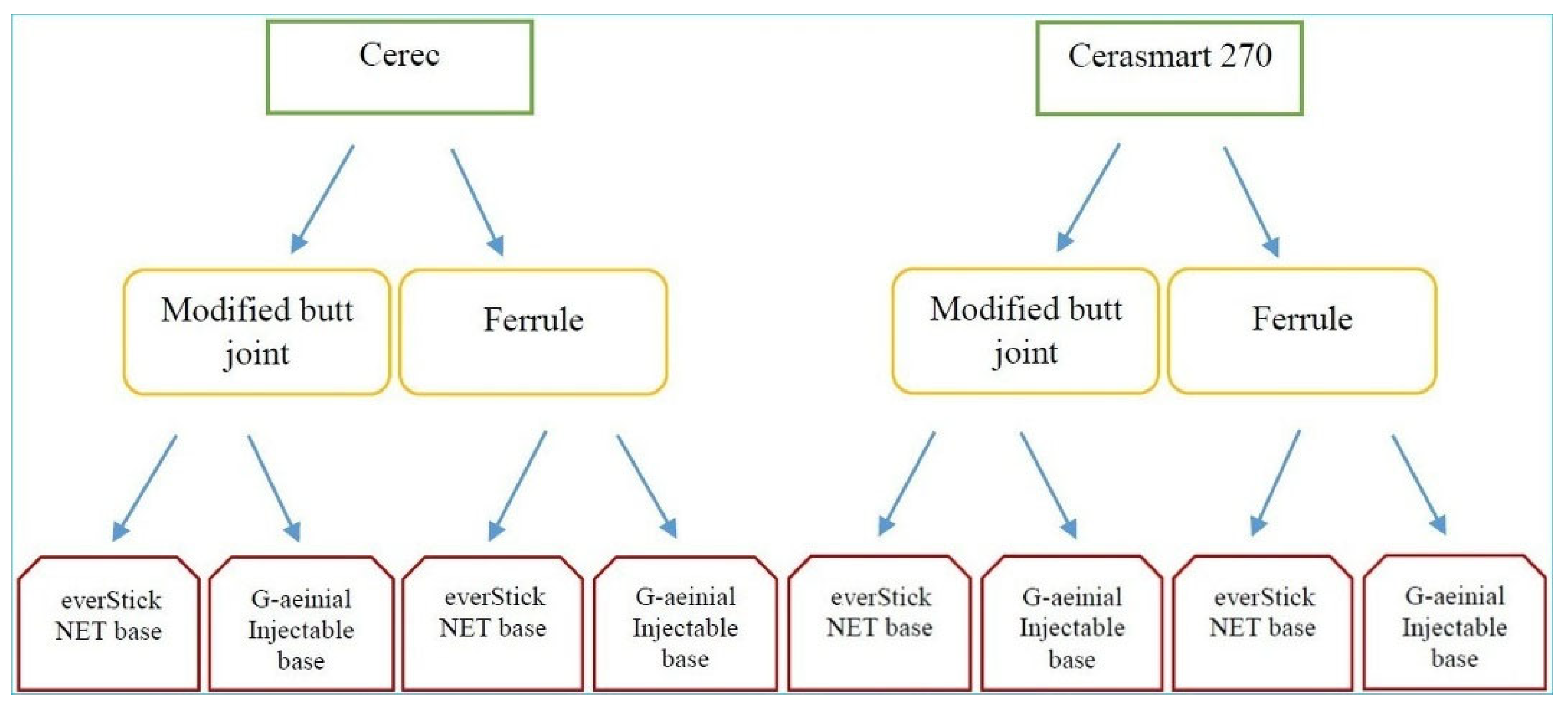
Figure 2.
Endocrown preparation and testing process. (a) Design of base with fiber. CEJ, cementoenamel junction; (b) Cavity with modified butt joint. Final view of the preparation; (c) Horizontal section image obtained from the software program; (d) Marginal fit reference points. AMD, absolute marginal discrepancy; MD, marginal discrepancy; (e) Internal fit reference points in the mesiodistal section. D, distal; AX, axial; PU, pulpal; M, mesial; (f) Fracture strength test.
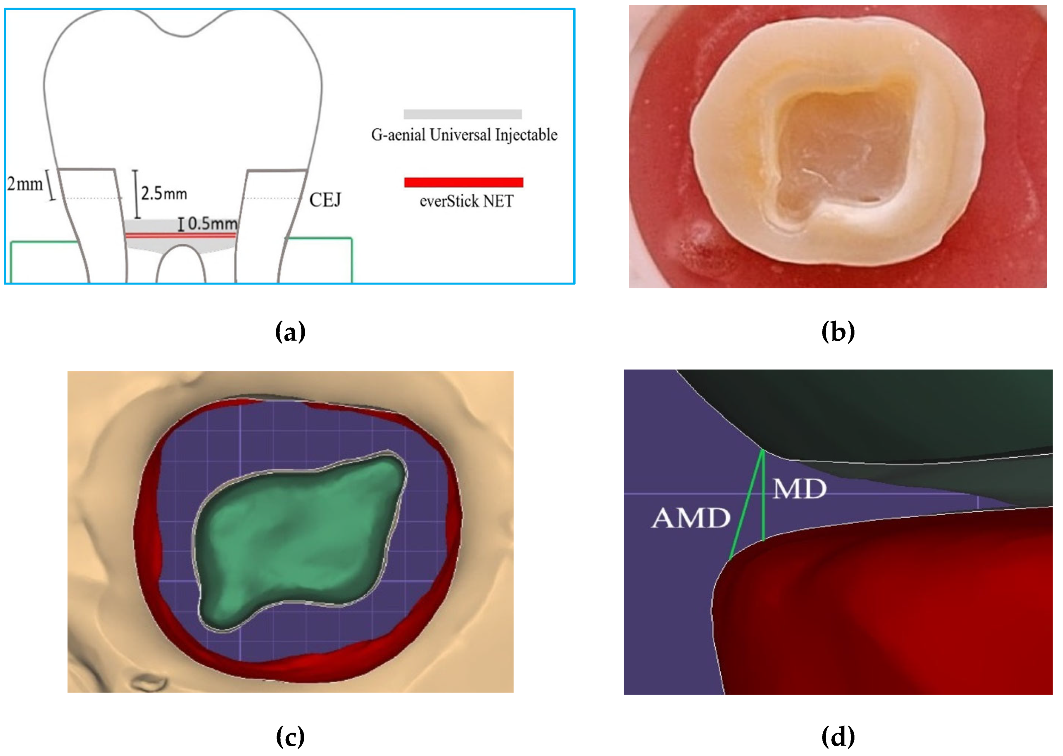
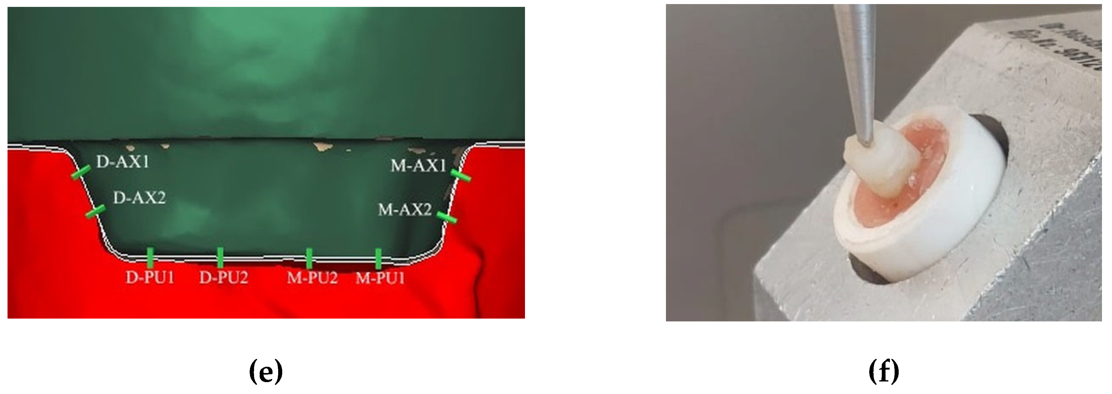
Figure 3.
Preparation of the fiber base. (a) Flowable resin is applied; (b) Fiber ribbon is cut and arranged; (c, d) Two layers of fiber ribbon are placed in the cavity; (e, f) Flowable resin is applied.
Figure 3.
Preparation of the fiber base. (a) Flowable resin is applied; (b) Fiber ribbon is cut and arranged; (c, d) Two layers of fiber ribbon are placed in the cavity; (e, f) Flowable resin is applied.
Figure 4.
Fit assessment with computer software. (a) Mesiodistal section of a tooth with a modified butt joint. One of the retention grooves is seen in the yellow circle; (b) Buccolingual cross-sectional view of one of the hybrid ceramic restorations with ferrule and fiber. The measurement value from the lingual pulpal-2 reference point was 131 µm; (c) Marginal discrepancy measurement in restoration with fiber and ceramic. The value obtained was 102 µm; (d) Marginal discrepancy measurement in restoration without fiber and with hybrid ceramic. The value obtained was 113 µm.
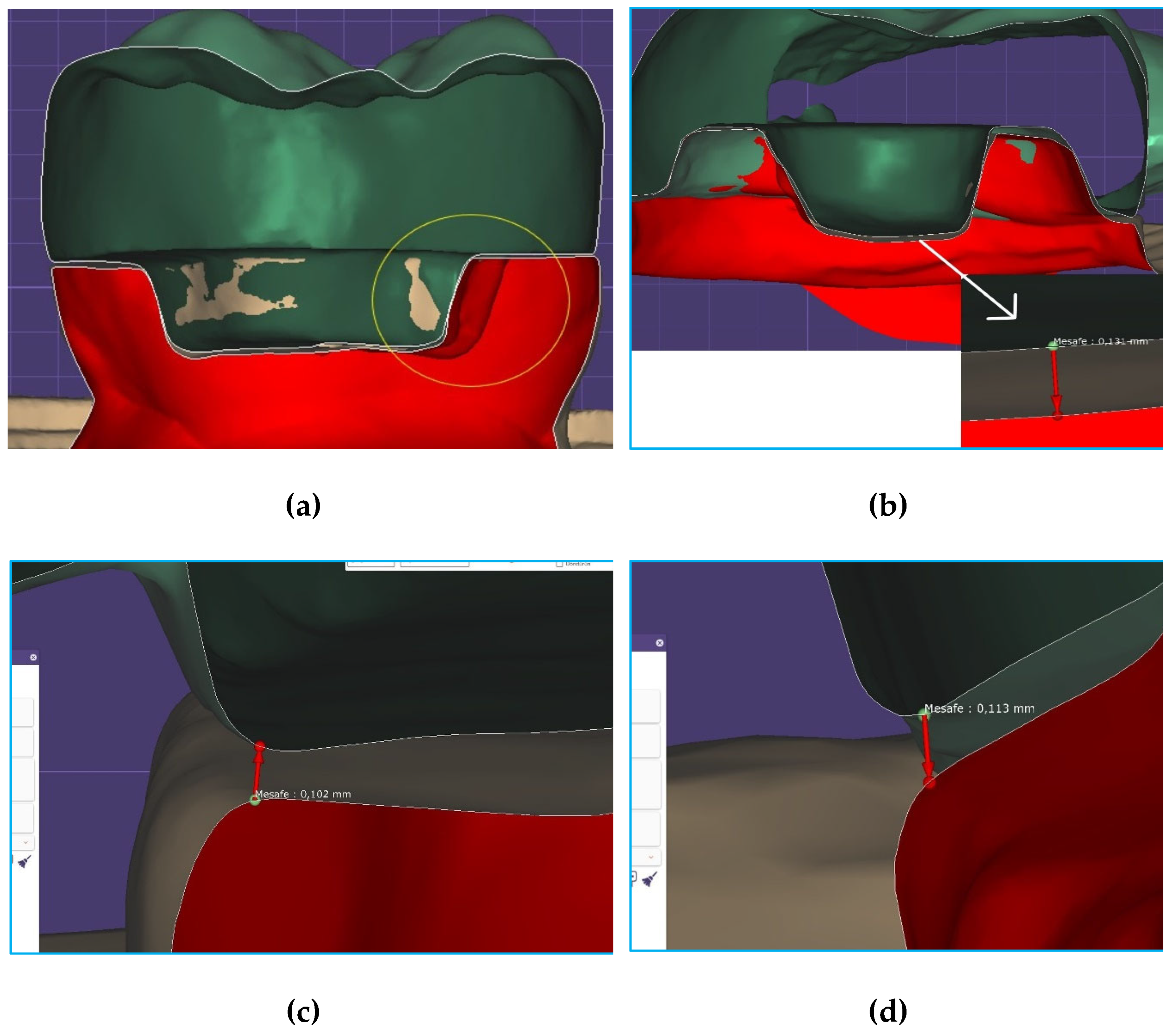
Figure 5.
Results for failure types. Type I: Cohesive failure in endocrown, Type II: Adhesive failure between endocrown and dentin, Type III: Cohesive failure in enamel/dentin, Type IV: Fracture extending towards the root, above the cementoenamel junction, Type V: Fracture extending below the cementoenamel junction (irreparable). CE, Cerec; CS, Cerasmart 270; BJ, butt joint; ES, everStick NET; GU, G-aenial Injectable.
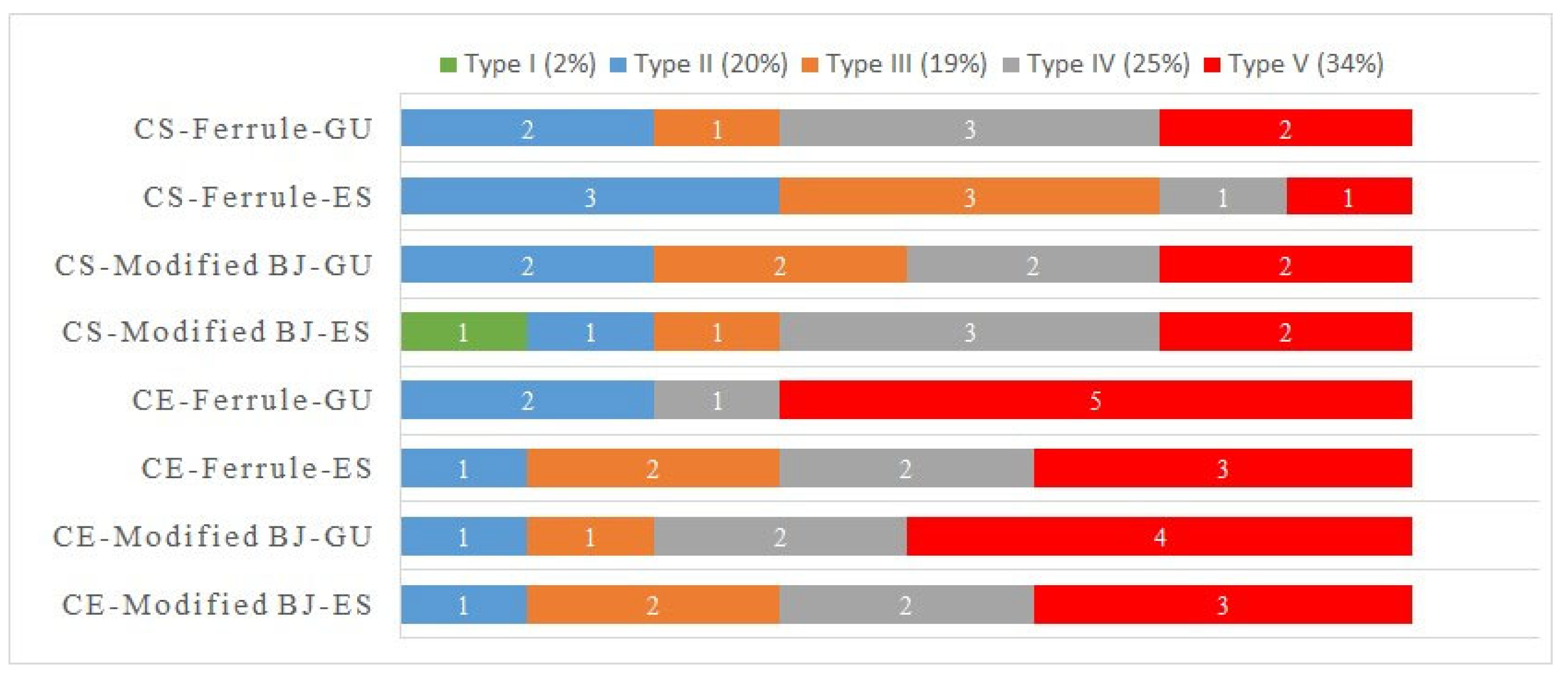
Figure 6.
Stereomicroscopy examination after fracture test. (a) Image of ceramic restoration with ferrule and fiber ribbon. The ferrule was preserved but the restorative material-dentin bond appeared to be broken; (b) Tooth with ferrule and fiber ribbon. Both the adhesive bond was broken and the ferrule was fractured; (c) Image of ceramic restoration with fiber ribbon and modified butt joint. The blue arrow shows one of the horizontally propagating cracks; (d) Tooth with fiber ribbon and modified butt joint. The red circle shows the relationship between the groove and the base material; (e) Image of hybrid ceramic restoration. Tooth without fiber ribbon and ferrule. Fracture of the restorative material was observed, but the integrity of the ferrule was preserved; (f) Hybrid ceramic restoration. Tooth with fiber ribbon and modified butt joint. The red circle shows an irreparable fracture extending below the cementoenamel junction; (g) Images of tooth without fiber ribbon. Hybrid ceramic restoration with ferrule. The restorative material showed fracture but overall integrity was preserved; (h) Tooth without fiber ribbon. Ceramic restoration with modified butt joint. The blue arrow indicates an irreparable fracture extending below the cementoenamel junction.
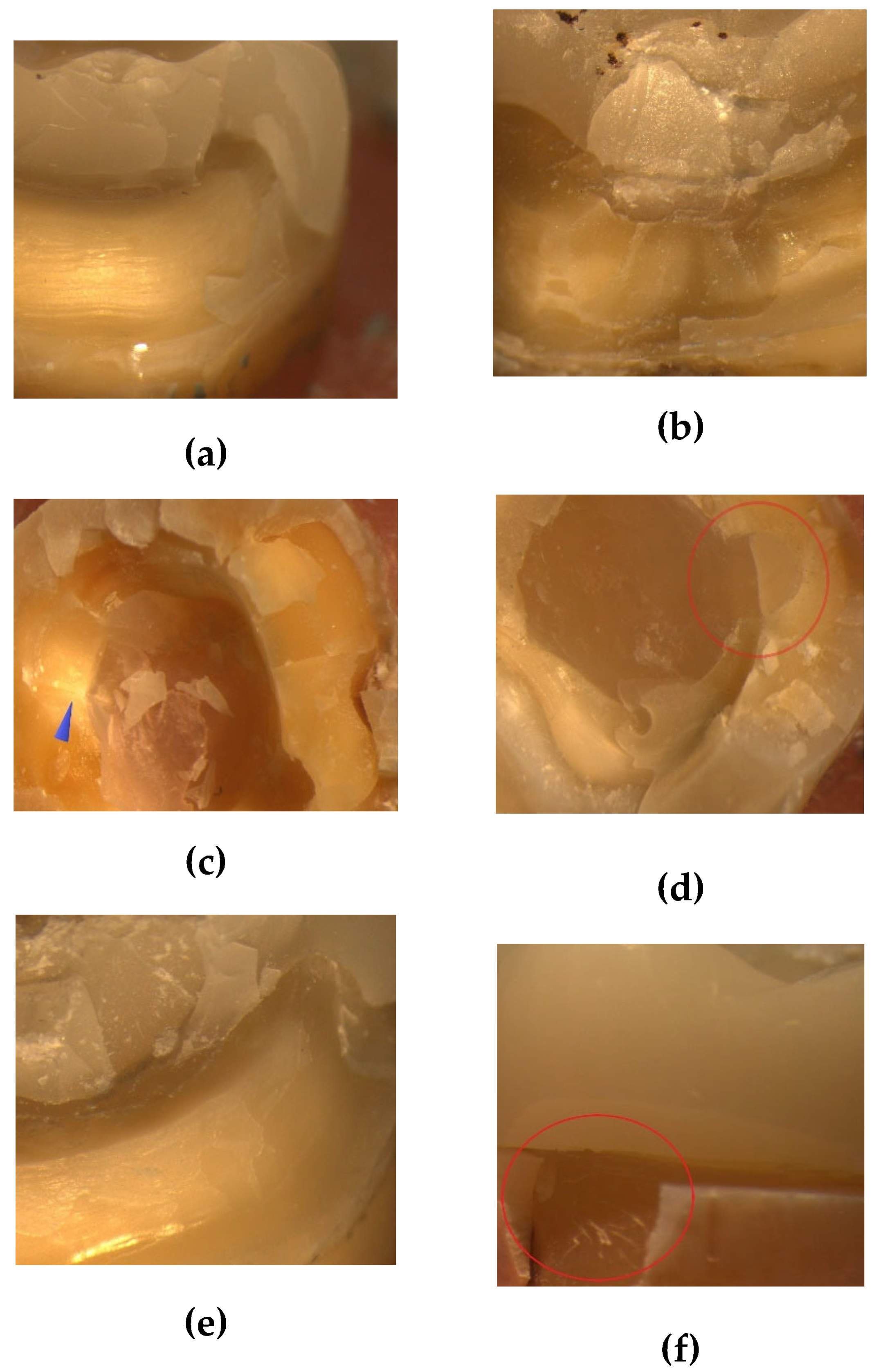
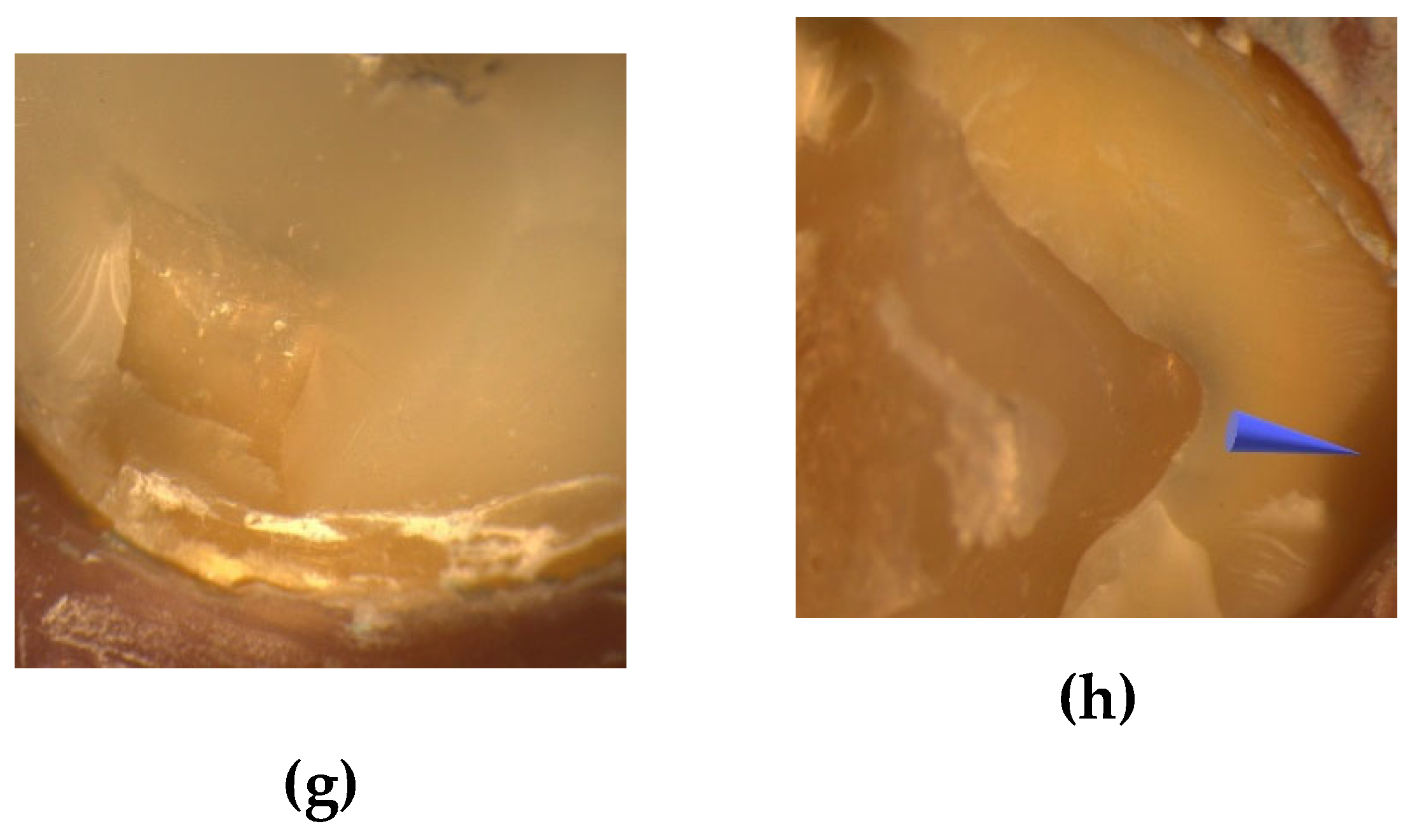

Table 1.
Materials used in the study.
| Intended use | Code | Name | Feature | Content (% in weight) | Manufacturer |
|---|---|---|---|---|---|
| Pulpal base | GU | G-ænial Universal Injectable | Light-cured injectable composite | 31% matrix (methacrylate monomer), 69% fillers (silica, barium glass) | GC Corp, Tokyo, Japan |
| ES | everStick NET | Fiber ribbon | Bidirectional glass fibers, polymer/resin gel matrix (PMMA, Bis-GMA) | GC Corp, Tokyo, Japan | |
| Restorative material | CE | Cerec Blocs | Feldspathic ceramic blocs | 56-64% SiO2, 20-23% Al2O3, 6-9% Na2O, 6-8% K2O, 0.3-0.6% other oxides | Sirona Dental, Bensheim, Germany |
| CS | Cerasmart 270 | Hybrid ceramic blocs | 29% matrix (UDMA, Bis-MEPP, DMA), 71% fillers (300 nm barium glass; 20 nm SiO2 nanoparticles) | GC Corp, Tokyo, Japan |
SiO2, silicium dioxide; Al2O3, aluminium oxide; Na2O; sodium oxide; K2O, potassium oxide; Bis-GMA, bisphenol A-glycidyl methacrylate; PMMA, Polymethyl methacrylate; UDMA, urethane dimethacrylate; Bis-MEPP, Bismethacryloxyethoxydiphenylpropane; DMA, dodecyl dimethacrylate.
Table 2.
ANOVA results of AMD, MD, axial, pulpal, overall fits and fracture strength.
| Source | Sum of squares | df | F | p-value | Partial eta squared | |
|---|---|---|---|---|---|---|
| AMD | Material | 2626.563 | 1 | 4.596 | 0.036 | 0.076 |
| Preparation | 156.25 | 1 | 0.273 | 0.603 | 0.005 | |
| Base | 12.25 | 1 | 0.021 | 0.884 | 0.001 | |
| Material-preparation | 27.563 | 1 | 0.048 | 0.827 | 0.001 | |
| Material-base | 612.563 | 1 | 1.072 | 0.305 | 0.019 | |
| Preparation-base | 1156 | 1 | 2.023 | 0.16 | 0.035 | |
| Material-preparation-base | 248.063 | 1 | 0.434 | 0.513 | 0.008 | |
| MD | Material | 756.25 | 1 | 5.589 | 0.022 | 0.091 |
| Preparation | 34.516 | 1 | 0.255 | 0.616 | 0.005 | |
| Base | 54.391 | 1 | 0.402 | 0.529 | 0.007 | |
| Material-preparation | 2.641 | 1 | 0.02 | 0.889 | 0.001 | |
| Material-base | 102.516 | 1 | 0.758 | 0.388 | 0.013 | |
| Preparation-base | 60.063 | 1 | 0.444 | 0.508 | 0.008 | |
| Material-preparation-base | 18.063 | 1 | 0.133 | 0.716 | 0.002 | |
| Axial fit | Material | 650.25 | 1 | 6.197 | 0.016 | 0.1 |
| Preparation | 240.25 | 1 | 2.29 | 0.136 | 0.039 | |
| Base | 22.563 | 1 | 0.215 | 0.645 | 0.004 | |
| Material-preparation | 6.25 | 1 | 0.06 | 0.808 | 0.001 | |
| Material-base | 52.563 | 1 | 0.501 | 0.482 | 0.009 | |
| Preparation-base | 39.063 | 1 | 0.372 | 0.544 | 0.007 | |
| Material-preparation-base | 5.063 | 1 | 0.048 | 0.827 | 0.001 | |
| Pulpal fit | Material | 2588.266 | 1 | 13.491 | < 0.001 | 0.194 |
| Preparation | 1113.891 | 1 | 0.281 | 0.598 | 0.005 | |
| Base | 3150.016 | 1 | 0.281 | 0.598 | 0.005 | |
| Material-preparation | 446.266 | 1 | 0.052 | 0.821 | 0.001 | |
| Material-base | 293.266 | 1 | 0.206 | 0.651 | 0.004 | |
| Preparation-base | 43.891 | 1 | 0.116 | 0.735 | 0.002 | |
| Material-preparation-base | 54.391 | 1 | 0.323 | 0.572 | 0.006 | |
| Overall fit | Material | 1602.501 | 1 | 18.398 | < 0.001 | 0.247 |
| Preparation | 78.766 | 1 | 0.904 | 0.346 | 0.016 | |
| Base | 126.563 | 1 | 1.453 | 0.233 | 0.025 | |
| Material-preparation | 6.25 | 1 | 0.072 | 0.79 | 0.001 | |
| Material-base | 183.941 | 1 | 2.112 | 0.152 | 0.036 | |
| Preparation-base | 153.915 | 1 | 1.767 | 0.189 | 0.031 | |
| Material-preparation-base | 1.806 | 1 | 0.021 | 0.886 | 0.001 | |
| Fracture strength | Material | 932575.214 | 1 | 87.424 | < 0.001 | 0.61 |
| Preparation | 955052.36 | 1 | 89.531 | < 0.001 | 0.615 | |
| Base | 1493630.413 | 1 | 140.02 | < 0.001 | 0.714 | |
| Material-preparation | 5878.626 | 1 | 0.551 | 0.461 | 0.01 | |
| Material-base | 22564.026 | 1 | 2.115 | 0.151 | 0.036 | |
| Preparation-base | 45216.506 | 1 | 4.239 | 0.044 | 0.07 | |
| Material-preparation-base | 5402.61 | 1 | 0.506 | 0.48 | 0.009 | |
Significant association (p < 0.05) indicated in bold. AMD, absolute marginal discrepancy; MD, marginal discrepancy.
Table 3.
Means ± standard deviations of AMD, MD, axial, pulpal, overall fits and fracture strength.
|
Material |
Preparation |
N |
Base |
Means ± standard deviations | |||||
|
AMD (µm) |
MD (µm) |
Axial (µm) |
Pulpal (µm) |
Overall (µm) |
FS (N) |
||||
| CE |
Modified BJ |
8 | ES | 136 ± 18 | 112 ± 7 | 106 ± 9 | 146 ± 22 | 124 ± 6 | 648 ±148 |
| 8 | GU | 119 ± 15 | 108 ±8 | 102 ± 7 | 128 ± 30 | 114 ± 3 | 451 ± 67 | ||
| 16 | Total | 128 ± 18 | 110 ±7 | 104 ± 8 | 137 ± 27 | 119 ± 7 | 549 ± 150 | ||
|
Ferrule |
8 | ES | 122 ± 25 | 107 ± 10 | 109 ± 13 | 149 ± 31 | 122 ± 6 | 944 ± 117 | |
| 8 | GU | 129 ± 32 | 109 ± 11 | 107 ± 6 | 131 ± 33 | 119 ± 6 | 605 ± 86 | ||
| 16 | Total | 125 ± 28 | 108 ± 10 | 108 ± 10 | 140 ± 32 | 120 ± 6 | 774 ± 201 | ||
| Total | 16 | ES | 129 ± 22 | 109 ± 9 | 107 ± 11 | 148 ± 26 | 123 ± 6 | 796 ± 200 | |
| 16 | GU | 124 ± 25 | 108 ± 9 | 104 ± 7 | 129 ± 30 | 117 ± 5 | 528 ± 109 | ||
| 32 | Total | 127 ± 23 | 108 ± 9 | 106 ± 9 | 139 ± 29 | 120 ± 6 | 662 ± 209 | ||
| CS |
Modified BJ |
8 | ES | 140 ± 22 | 115 ± 8 | 111 ± 11 | 151 ± 23 | 129 ± 13 | 926 ± 106 |
| 8 | GU | 143 ± 18 | 118 ± 11 | 110 ± 8 | 138 ± 20 | 127 ± 11 | 617 ± 72 | ||
| 16 | Total | 142 ± 19 | 116 ± 10 | 111 ± 10 | 145 ± 22 | 128 ± 11 | 772 ± 182 | ||
|
Ferrule |
8 | ES | 131 ± 27 | 113 ± 16 | 112 ± 11 | 161 ± 13 | 129 ± 8 | 1224 ± 105 | |
| 8 | GU | 143 ± 25 | 118 ± 15 | 115 ± 11 | 155 ± 17 | 133 ± 12 | 846 ± 98 | ||
| 16 | Total | 137 ± 26 | 115 ± 15 | 114 ± 10 | 158 ± 15 | 131 ±10 | 1035 ± 218 | ||
| Total | 16 | ES | 136 ± 24 | 114 ± 12 | 112 ± 11 | 156 ± 19 | 129 ± 10 | 1075 ± 185 | |
| 16 | GU | 143 ± 21 | 118 ± 13 | 113 ± 10 | 147 ± 20 | 130 ± 12 | 732 ± 144 | ||
| 32 | Total | 139 ± 23 | 116 ± 13 | 112 ± 10 | 151 ± 20 | 130 ± 11 | 903 ± 238 | ||
| Overall |
Modified BJ |
16 | ES | 138 ± 19 | 114 ± 7 | 108 ± 10 | 149 ± 19 | 127 ± 10 | 787 ± 190 |
| 16 | GU | 131 ± 20 | 113 ± 11 | 106 ± 8 | 133 ± 25 | 121 ± 10 | 534 ± 109 | ||
| 32 | Total | 135 ± 20 | 113 ± 9 | 107 ± 9 | 141 ± 25 | 124 ± 10 | 660 ± 199 | ||
|
Ferrule |
16 | ES | 127 ± 16 | 110 ± 13 | 110 ± 12 | 155 ± 24 | 126 ± 8 | 1084 ± 180 | |
| 16 | GU | 136 ± 29 | 113 ± 14 | 112 ± 9 | 143 ± 28 | 126 ± 12 | 725 ± 153 | ||
| 32 | Total | 131 ± 27 | 112 ± 13 | 111 ± 10 | 149 ± 26 | 126 ± 10 | 905 ± 245 | ||
| Total | 32 | ES | 133 ± 23 | 111 ± 11 | 110 ± 11 | 152 ± 23 | 126 ± 9 | 935 ± 236 | |
| 32 | GU | 134 ± 25 | 113 ± 12 | 109 ± 9 | 138 ± 27 | 123 ± 11 | 630 ± 163 | ||
| 64 | Total | 133 ± 24 | 112 ± 11 | 109 ± 10 | 145 ± 26 | 125 ± 10 | 783 ± 253 | ||
CE, Cerec; CS, Cerasmart 270; ES, everStick NET; GU, G-aenial Injectable; BJ, butt joint; AMD, absolute marginal discrepancy; MD, marginal discrepancy; FS, fracture strength.
Table 4.
Pairwise interaction results for fracture strength (N).
| Material-preparation | ||||
| Mean | 95% Confidence interval | |||
| Lower bound | Upper bound | |||
| CE | Modified BJ | 549 | 497 | 601 |
| Ferrule | 774 | 722 | 826 | |
| CS | Modified BJ | 771 | 719 | 823 |
| Ferrule | 1035 | 98 | 1086 | |
| Material-base | ||||
| Mean | 95% Confidence interval | |||
| Lower bound | Upper bound | |||
| CE | ES | 795 | 744 | 847 |
| GU | 527 | 476 | 579 | |
| CS | ES | 1074 | 102 | 1126 |
| GU | 731 | 680 | 783 | |
| Preparation-base | ||||
| Mean | 95% Confidence interval | |||
| Lower bound | Upper bound | |||
| Modified BJ | ES | 786 | 734 | 838 |
| GU | 534 | 482 | 586 | |
| Ferrule | ES | 1084 | 1032 | 1135 |
| GU | 725 | 673 | 777 | |
CE, Cerec; CS, Cerasmart 270; BJ, butt joint; ES, everStick NET; GU, G-aenial Injectable.
Disclaimer/Publisher’s Note: The statements, opinions and data contained in all publications are solely those of the individual author(s) and contributor(s) and not of MDPI and/or the editor(s). MDPI and/or the editor(s) disclaim responsibility for any injury to people or property resulting from any ideas, methods, instructions or products referred to in the content. |
© 2025 by the authors. Licensee MDPI, Basel, Switzerland. This article is an open access article distributed under the terms and conditions of the Creative Commons Attribution (CC BY) license (http://creativecommons.org/licenses/by/4.0/).
Copyright: This open access article is published under a Creative Commons CC BY 4.0 license, which permit the free download, distribution, and reuse, provided that the author and preprint are cited in any reuse.


