Submitted:
21 April 2025
Posted:
22 April 2025
You are already at the latest version
Abstract
This report presents the detailed design and realization of the training of a network infrastructure for a medium-sized business. The aim is to provide versatile, secure, and efficient networking for the operational requirements of nearly 30 employees, plus dedicated rooms for server, printing, conference, and surveillance purposes. The network employs a ring topology for efficient data transfer and utilizes a combination of static routing, IP addressing, and subnetting so as to perform optimally and leave space for possible expansion as required. Some of the salient features include secured entry through keycard systems, wireless and wired connectivity, departmental segmentation via subnets, and redundancy offered by multiple routers and switches. This design of the enterprise architecture is aimed at preventing downtimes, supporting growth, and safeguarding secure and uniform access for all users.
Keywords:
security
; privacy
; scalability
; network infrastructure
1. Introduction
Much of the business function in the modern digital world hinges on the reliability and scalability of a network infrastructure on which it operates. This particular work is in line with the development of a complete network system into an enterprise that has an average of about thirty employees or varied operational departments. The main objective of erecting this network is to ensure that it is secure, efficient, and scalable according to the present needs of the business, but more importantly, it should not constrain tomorrow’s growth [1,2,3].
The design therefore translates into a two-story facility where the first story is to host servers and the printing office, while the second would comprise the interior department’s Finance, Sales, Customer Service, IT, and executive functions. A structured network topology that is a ring is designed for high availability and high-speed data transmission while minimizing the effects of collision and consequently providing good performance across departments. Effective traffic management and simple network administration can be achieved through the strategic planning of IP addressing and subnetting. Security is assured by careful physical access and future planned firewall installation. This report provides floor plans and network diagrams as well as justification for design choices, static routing tables and the chosen topology: all serve to demonstrate a sound basis for digital operations in the enterprise [4,5].
The floor plan provided for mid-size company is shown in Figure 1. The first floor has not been developed to accommodate employees as it is dedicated to the servers. Further, it has a printing area to perform bulk printing. An area to sit is provided to connect the server and printing room for the visitors managing the server or waiting for the printer. The floor provides wireless connectivity to the internet for its visitors. Moreover, a key card machine will be established to keep unauthorized persons at bay from entering the premises. Visitors like maintenance crew have the privilege to avail of our premises ensured by entry along with one of the employees for privacy and security for our company [6].
Figure 1.
Floor 1 Floor Plan.
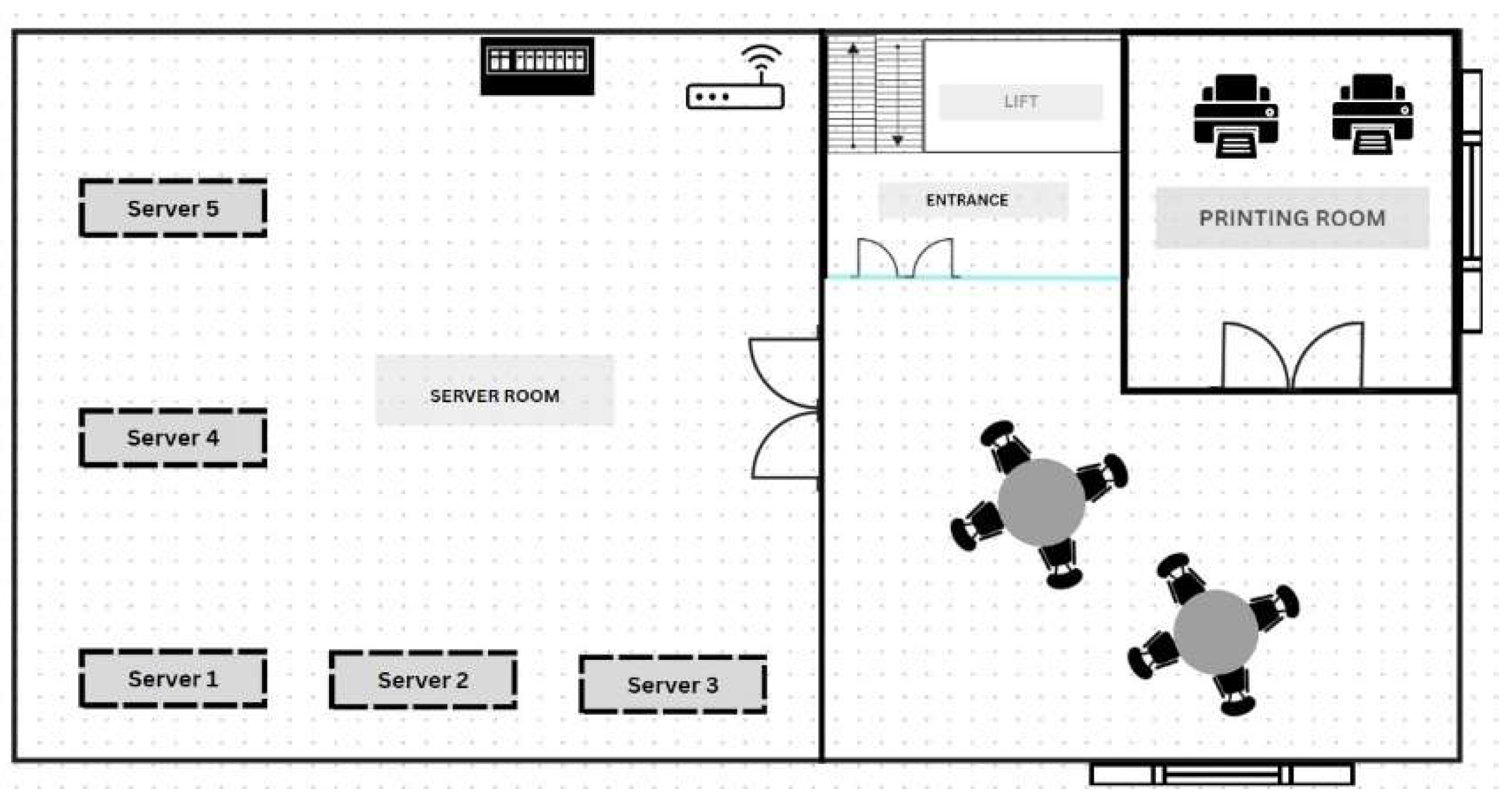
Figure 2.
Floor 2 Floor Plan.
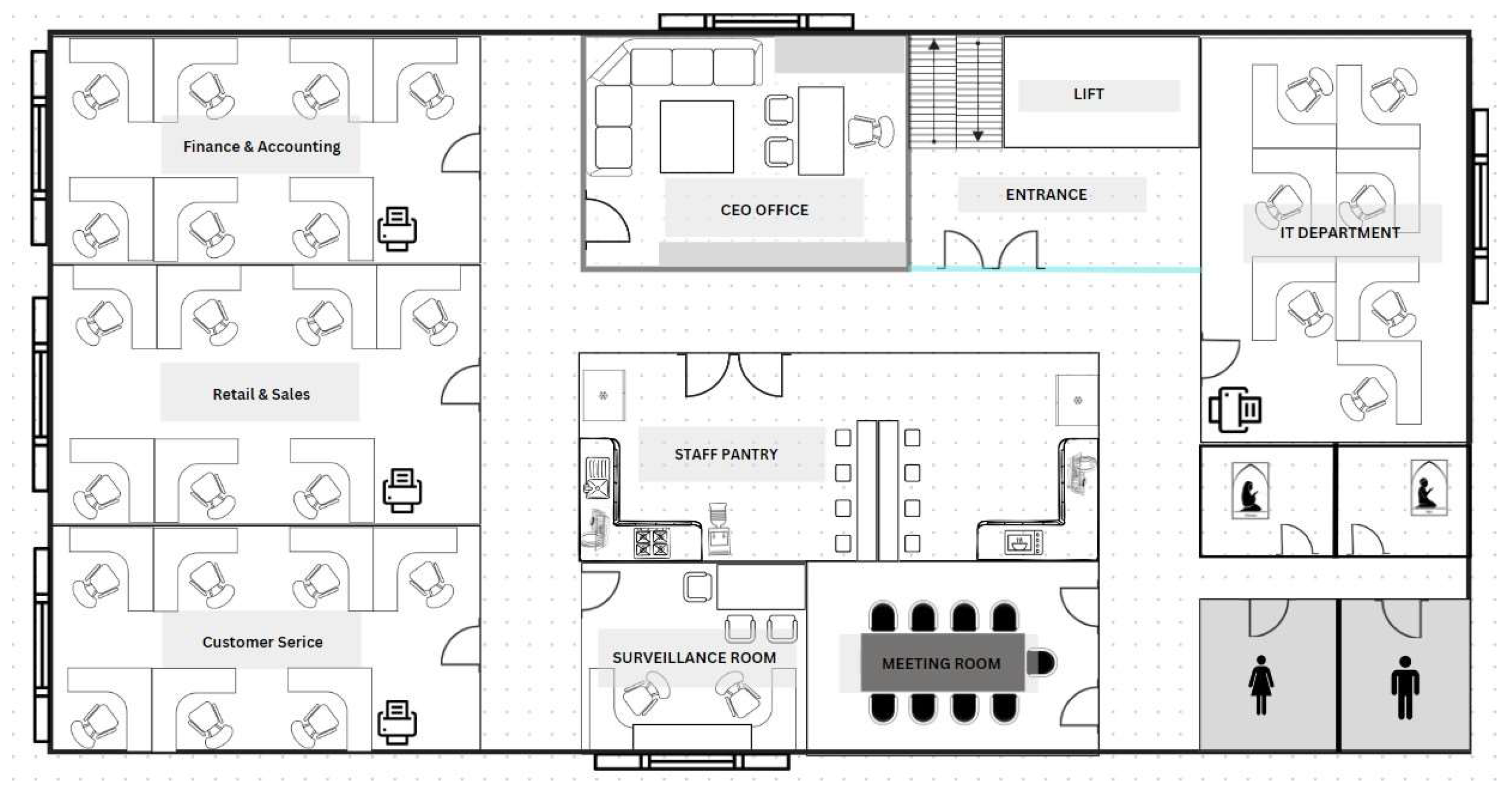
Alongside granting an independent working space for each department, a maximum capacity of 30 employees can therefore be accommodated on level two. In addition, we’ve allocated a surveillance room and a CEO’s office. Just for a little extra, we also provided a meeting room for 20 employees in departmental meetings or some discussions needing more than one department. This floor also accommodates a prayer room and restrooms for both genders. Key card access is further in place for this floor so that unauthorized individuals cannot access it [7].
Figure 3.
Network Diagram.
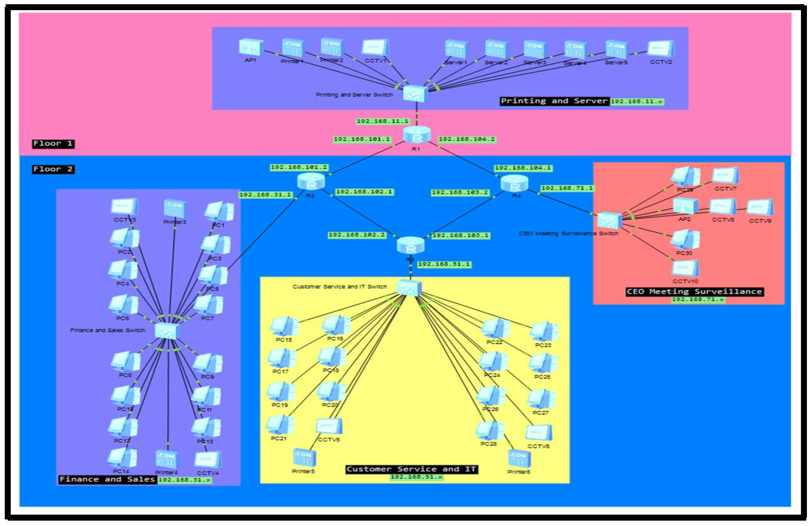
There are 4 subnets in the network with 30 PCs, 6 Printers, 2 Access Points, 5 Servers, 4 Switches and 4 Routers. The default gateway for floor one will be 192.168.11.1, for the Sales and Finance department is 192.168.31.1, for the Customer Service and IT department is 192.168.51.1 and for CEO’s room, Meeting rooms and surveillance room is 192.168.71.1. Network devices will be in their department. Furthermore, each communication between routers has its own network. R1 and R2 are using the network 192.168.101.x, R2 and R3 are using the network 192.168.102.x, R3 and R4 use 192.168.103.x and R4 and R1 use the network 192.168.104.x as show in Table 1 and Table 2.
2. Literature Review
Network topology is a key aspect of developing scalable and fault-tolerant enterprise networks. Ring topology, which is used within this project, has each machine connected to only two other devices through a ring-shaped data path. According to authors recommendations [8], this topology achieves effective data transmission as traffic flows in a single direction, which reduces packet collision and aids in load balancing. Moreover, fault detection and isolation are simpler for ring topologies since network monitoring software is able to identify and correct connection faults instantly [10,11].
The use of static routing in this architecture supplements the inherent ring structure. Static routing is preferred in small, well-organized networks with lower change rates. Static routing simplifies routing tables and improves predictability [12]. Although it lacks the flexibility of dynamic routing protocols, simplicity supplements inherent performance constancy, making it suitable for medium-scale business organizations with pre-coded traffic behaviors.
IP addressing and subnetting techniques also occupy a core role in network effectiveness and security maintenance. In every subnet, the subnet mask 255.255.255.0 was chosen to have a large number of hosts per subnet and to maintain organized traffic control by departments. The Network Seal [13] declares that these subnetting schemes in Class C networks allow for growth scalability and simple IP management.
Local Area Networks (LANs), such as the one established in this project, benefit from structured segmentation by departments, with their own IP blocks. This not only improves security but also permits easier fault identification and maintenance. As the outlines, structured LAN designs using segmented topology and distributed switches lead to improved performance and expansion readiness [14].
Overall, the literature confirms the network design rationale—favoring ring topology, static routing, and departmental subnetting—as suitable for a growing medium-sized company in need of performance, scalability, and fault tolerance.
3. Methodology
The approach used in this project was a systematic network planning method, beginning with the analysis of the physical layout and proceeding through to logical network configuration. The first phase was requirement gathering, where the needs of the company were established in terms of the number of employees, departmental structures, and expansion in the future. Based on floor plan analysis, certain of the key features such as a dedicated server room, departmental segregation, and restricted access were included to satisfy functionality along with security [15,16,17].
Subsequently, the appropriate network topology was selected. Ring topology was implemented after extensive research and keeping in mind the fault tolerance, scalability, and best data routing requirements of the organization. This choice is in favor of medium-sized company local area network (LAN) best practices that provide a stable and expandable infrastructure [18,19,20]. Following the determination of the topology, IP address planning and subnetting were undertaken. A logical IP addressing scheme was devised, allocating four separate subnets to different departments: 192.168.11.0/24 for the print and server area, 192.168.31.0/24 for Sales and Finance, 192.168.51.0/24 for IT and Customer Service, and 192.168.71.0/24 for the CEO office, Meeting Room, and Surveillance. Each subnet utilized a default subnet mask of 255.255.255.0 for a maximum of 254 usable hosts, leaving space for expansion.
Static routing configuration was then implemented using manual routing table configuration in each of the routers that formed the ring topology. This gave direct control of department-to-department traffic and minimal routing overhead, which reduced complexity that typically comes with dynamic routing protocols. Device allocation and network segmentation were then performed, where switches and routers were assigned according to department layout and estimated device load. Each hardware item, including PCs, servers, printers, and access points, had a static IP address assigned to avoid conflicts as well as network management issues.
For more robust physical as well as network security, key card systems were introduced at central access points on both floors. Secure Wi-Fi access was also recommended with log-in credentials, along with the introduction of adding a firewall at later stages to provide better security for data and user privacy too. Finally, the network configuration was confirmed by generating simulated network maps and detailed IP addressing tables. These graphical and tabular representations ensured readability, confirmed the functionality of the setup, and facilitated documentation of the overall network structure.
This Figure 4 depicts the static routes that have been set up on Router 1. These routes define the paths used in order to reach different subnets across the network, so that information meant for Finance and Sales, Customer Service and IT, and CEO’s office networks will be routed efficiently. Router 1 is one of the central nodes in the ring topology and a key intermediary in allowing inter-departmental communication.
Figure 5 show the Router 2’s static routing table, as shown here, contains entries that allow it to forward packets to their respective neighboring routers and departments. This is crucial in maintaining the logical flow of traffic and allows for the ring topology’s redundant data paths that enhance fault tolerance.
Figure 6 depicts Router 3’s routing setup that gives good data delivery to the Customer Service and IT department. Router 3 is connected to Router 2 and Router 4, continuing the ring’s logical loop and ensuring a continuation of communication even if one link is severed.
Above Figure 7 shows the Router 4 closes the ring by returning to Router 1 and by continuing its connections to the CEO’s office and security systems. Its static routing table helps in smooth communication in the network and offers backup routing paths in case of failure of other segments.
As illustrated in Figure 8, this network design is based on a ring topology. The subnet mask for this network is 255.255.255.240 which can support a maximum of 16 hosts. There are 4 routers being used in our current design, but additional routers can be used if the company wants to extend the company to other floors using the assistance of other IP addresses.
According to the NetworkSeal (2016), the table below demonstrates some subnet masks and their host capacity. The table is a guide to why the subnet mask 255.255.255.0 was chosen to be used in the internal departmental subnets, giving 254 usable host Ips per subnet. This allows for departmental growth and offers redundancy for network growth.
Results and Discussion
The network architecture in this project is a good and effective method of installing a fault-tolerant and expandable LAN for a medium-sized business. The installation of a ring topology, as indicated in Figure 8, forms a circular configuration of routers by which data can be passed in a loop. This layout significantly enhances fault tolerance, as the failure of a single router or connection will not cut off any department—traffic can simply be rerouted in the opposite direction.
Routing was accomplished using static tables (Figures 4 through 7), building up permanent and secure paths for network traffic. The tables ensure inter-department communication becomes effective and free from the complexity of dynamic routing protocols. Static routing lacks automatic adaptability but has its deterministic nature most suitable for managed environments like this firm, where the network topology is fixed and known in advance.
Subnetting was the second primary focus of concern with the design. As outlined within the IP address section and verified by Figure 9, having a /24 subnet mask (255.255.255.0) selected for all four primary subnets provided a level of balance among available address room and simplicity. This allows every department to process a high amount of devices and provides room to grow without an extensive reconfigure.
Static IP addressing across the network prevents IP conflicts and ensures easier functionality, especially for critical devices such as servers, printers, and surveillance systems. The static configuration allows for easier security and reduced administrative hassle in the long run.
Security concerns were incorporated through the addition of key card access systems and the recommendation of secure wireless login systems. While these are minimum security standards, the discussion also made a point of emphasizing the need for future implementations such as firewalls and user authentication protocols, which would work to protect the network and sensitive company data.
Overall, the network performance, resilience, and scalability were clearly demonstrated through the static route configuration, IP segmentation, and ring topology. The results demonstrate that the proposed design meets the immediate needs of the company while being flexible enough to allow future technological and organizational growth.
Conclusion
In conclusion, we have designed a floor plan and network diagram for the company that is scalable and has several backups through the use of several Access Points, Routers and Switches. This enables the company to operate even in case of a Switch issue since there are numerous other network devices to sustain the system. Future developments can include a firewall to secure the users as well as the server’s data. The firm can also opt to create a username and password to use in entering the network so that people who are in other floors of the building cannot steal the wireless link for the company.
References
- Amin, N. U. , Junayen, A. A., Nasrullah, F. M., Mushtaq, M., & Alsukhailah, A. A. A. (2025). Design and implementation of a scalable network infrastructure for a mid-sized organization.
- Kim, H.-K.; So, W.-H.; Je, S.-M. A big data framework for network security of small and medium enterprises for future computing. J. Supercomput. 2019, 75, 3334–3367. [Google Scholar] [CrossRef]
- Pathirana, H.; Godagama, V.; Premadas, H.; Mailewa, A. Cost-Effective Investment to Monitor the Network Infrastructure of Small and Medium- Scale Enterprises. Int. J. Comput. Appl. 2023, 185, 33–38. [Google Scholar] [CrossRef]
- Odinma, A.C.; Butakov, S.; Grakhov, E.; Bollou, F. Planning, designing and implementing an enterprise network in a developing nation. Int. J. Enterp. Netw. Manag. 2008, 2, 301. [Google Scholar] [CrossRef]
- Rojas, H.; Arias, K.A.; Renteria, R. Service-oriented architecture design for small and medium enterprises with infrastructure and cost optimization. Procedia Comput. Sci. 2021, 179, 488–497. [Google Scholar] [CrossRef]
- Papathanasiou, A.; Liontos, G.; Katsouras, A.; Liagkou, V.; Glavas, E. Cybersecurity Guide for SMEs: Protecting Small and Medium-Sized Enterprises in the Digital Era. J. Inf. Secur. 2025, 16, 1–43. [Google Scholar] [CrossRef]
- Ugbebor, F.O. Intelligent cloud solutions bridging technology gaps for small and medium-sized enterprises. Journal of Artificial Intelligence General Science (JAIGS) 2024, 7, 161–186. [Google Scholar] [CrossRef]
- Liu, Z.; Sampaio, P.; Pishchulov, G.; Mehandjiev, N.; Cisneros-Cabrera, S.; Schirrmann, A.; Jiru, F.; Bnouhanna, N. The architectural design and implementation of a digital platform for Industry 4.0 SME collaboration. Comput. Ind. 2022, 138. [Google Scholar] [CrossRef]
- Saeed, S.; Abdullah, A.; Jhanjhi, N.Z.; Naqvi, M.; Nayyar, A. New techniques for efficiently k-NN algorithm for brain tumor detection. Multimedia Tools Appl. 2022, 81, 18595–18616. [Google Scholar] [CrossRef]
- Dogra, V. , Singh, A., Verma, S., Kavita, Jhanjhi, N. Z., & Talib, M. N. (2021). Analyzing DistilBERT for sentiment classification of banking financial news. In S. L. Peng, S. Y. Hsieh, S. Gopalakrishnan, & B. Duraisamy (Eds.), Intelligent computing and innovation on data science (Vol. 248, pp. 665–675). Springer. [CrossRef]
- Gopi, R.; Sathiyamoorthi, V.; Selvakumar, S.; Manikandan, R.; Chatterjee, P.; Jhanjhi, N.Z.; Luhach, A.K. Enhanced method of ANN based model for detection of DDoS attacks on multimedia internet of things. Multimedia Tools Appl. 2021, 81, 26739–26757. [Google Scholar] [CrossRef]
- Chesti, I. A. , Humayun, M., Sama, N. U., & Jhanjhi, N. Z. (2020, October). Evolution, mitigation, and prevention of ransomware. In 2020 2nd International Conference on Computer and Information Sciences (ICCIS) (pp. 1–6). IEEE.
- Alkinani, M.H.; Almazroi, A.A.; Jhanjhi, N.; Khan, N.A. 5G and IoT Based Reporting and Accident Detection (RAD) System to Deliver First Aid Box Using Unmanned Aerial Vehicle. Sensors 2021, 21, 6905. [Google Scholar] [CrossRef] [PubMed]
- Babbar, H.; Rani, S.; Masud, M.; Verma, S.; Anand, D.; Jhanjhi, N. Load Balancing Algorithm for Migrating Switches in Software-defined Vehicular Networks. Comput. Mater. Contin. 2021, 67, 1301–1316. [Google Scholar] [CrossRef]
- Humayun, M.; Jhanjhi, N.; Alsayat, A.; Ponnusamy, V. Internet of things and ransomware: Evolution, mitigation and prevention. Egypt. Informatics J. 2021, 22, 105–117. [Google Scholar] [CrossRef]
- Kaur, N.; Verma, S.; Kavita; Jhanjhi, N.Z.; Singh, S.; Ghoniem, R.M.; Ray, S.K. Enhanced QoS-Aware Routing Protocol for Delay Sensitive Data in Wireless Body Area Networks. IEEE Access 2023, 11, 106000–106012. [CrossRef]
- Singh, T.; Solanki, A.; Sharma, S.K.; Jhanjhi, N.Z.; Ghoniem, R.M. Grey Wolf Optimization-Based CNN-LSTM Network for the Prediction of Energy Consumption in Smart Home Environment. IEEE Access 2023, 11, 114917–114935. [Google Scholar] [CrossRef]
- Saeed, S. , Jhanjhi, N. Z., Naqvi, S. M. R., & Khan, A. (2022). Analytical Approach for Security of Sensitive Business Cloud. Deep Learning in Data Analytics: Recent Techniques, Practices and Applications, 257-266.
- Ashfaq, F., Jhanjhi, N. Z., & Khan, N. A. (2023, April). Badminton player’s shot prediction using deep learning. In Innovation and Technology in Sports: Proceedings of the International Conference on Innovation and Technology in Sports,(ICITS) 2022, Malaysia (pp. 233-243). Singapore: Springer Nature Singapore.
- Javed, D., Jhanjhi, N. Z., & Khan, N. A. (2023, July). Explainable Twitter bot detection model for limited features. In IET Conference Proceedings CP837 (Vol. 2023, No. 11, pp. 476-481). Stevenage, UK: The Institution of Engineering and Technology.
Figure 4.
Routing Table Router 1.
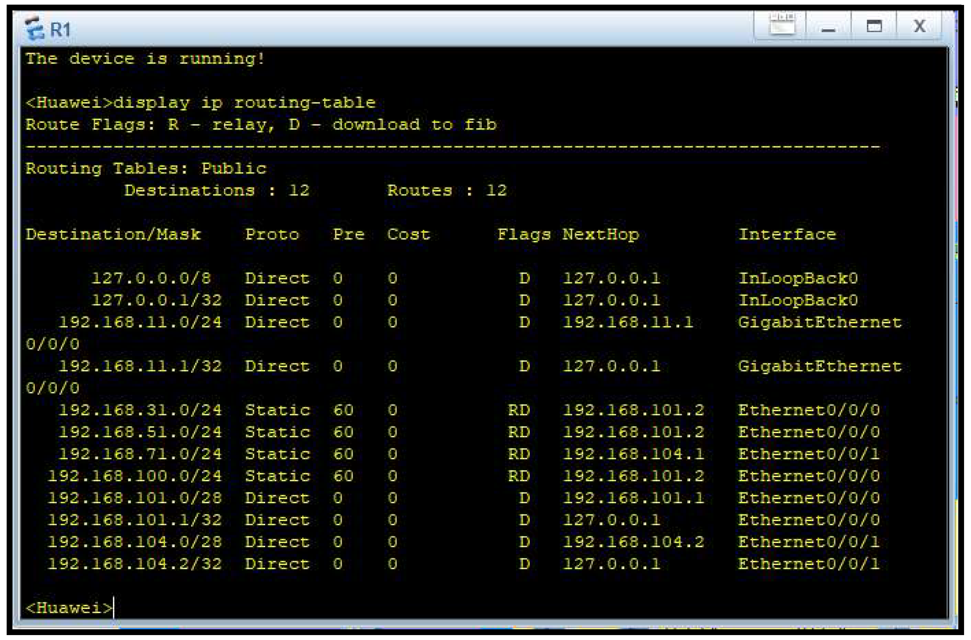
Figure 5.
Routing Table Router 2.
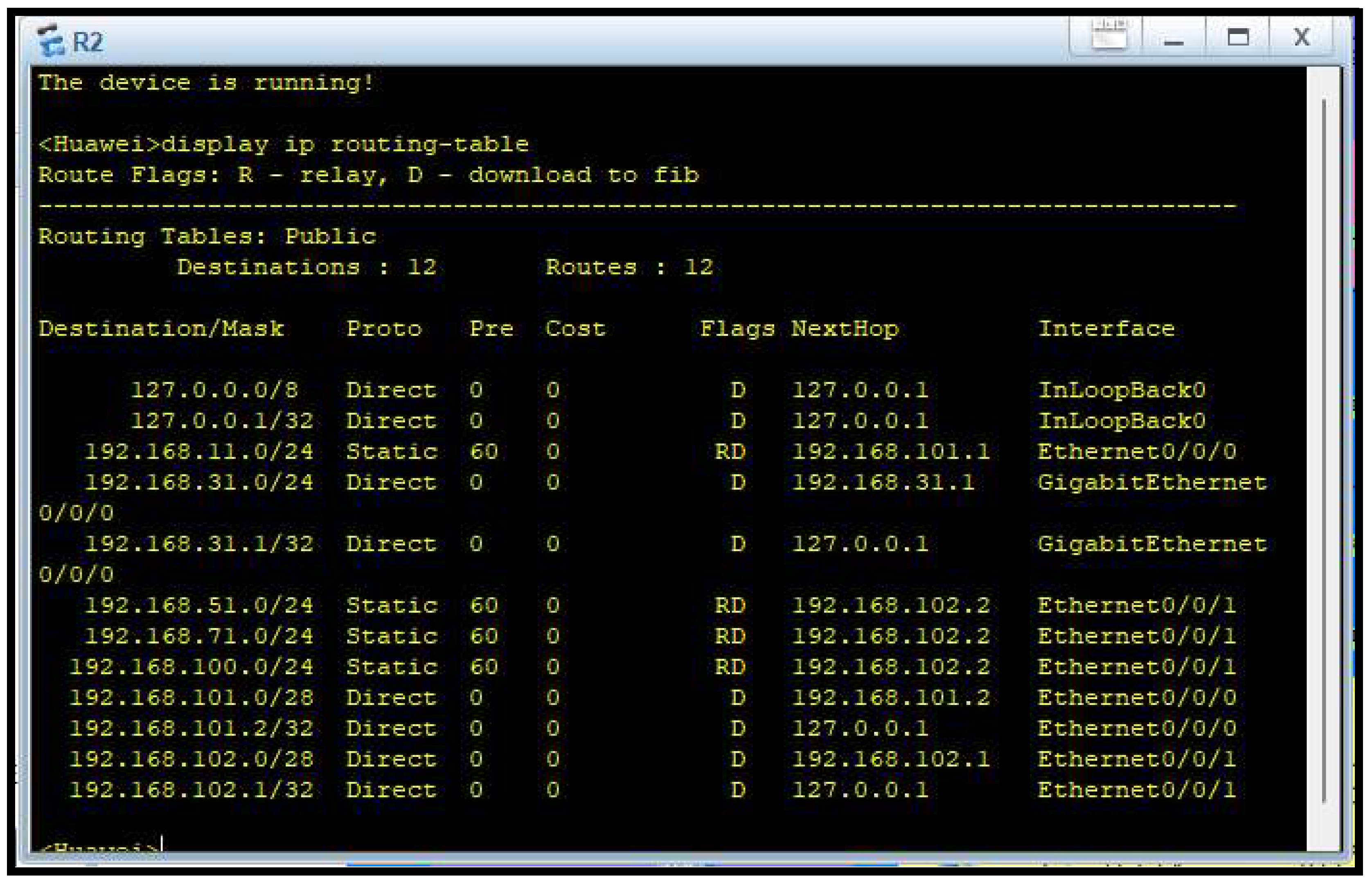
Figure 6.
Routing Table Router 3.
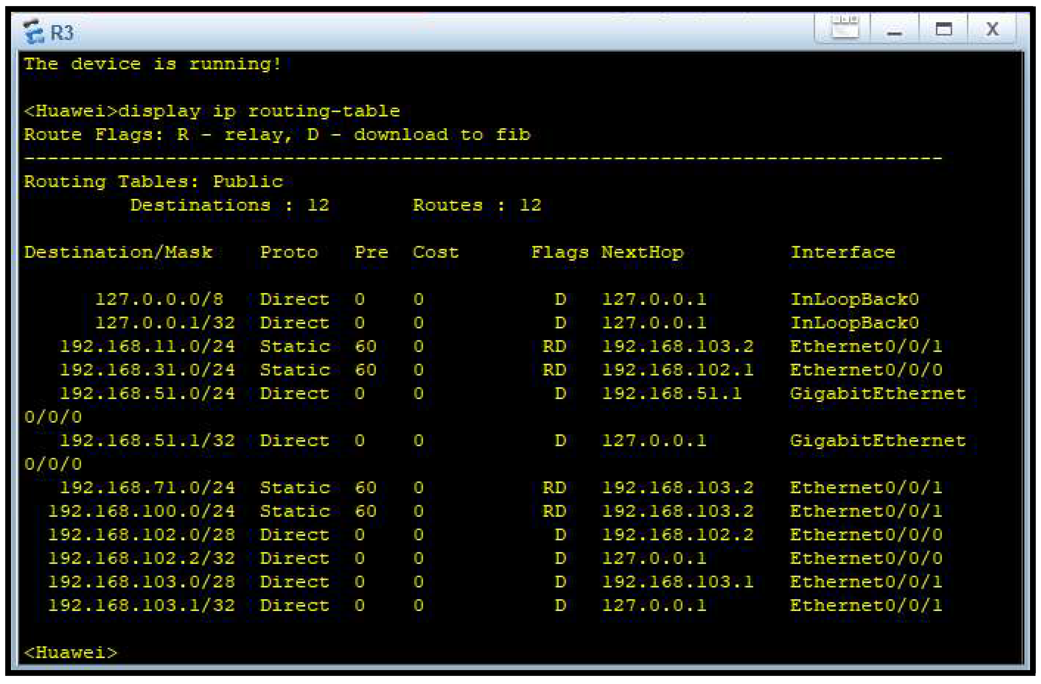
Figure 7.
Routing Table Router 4.
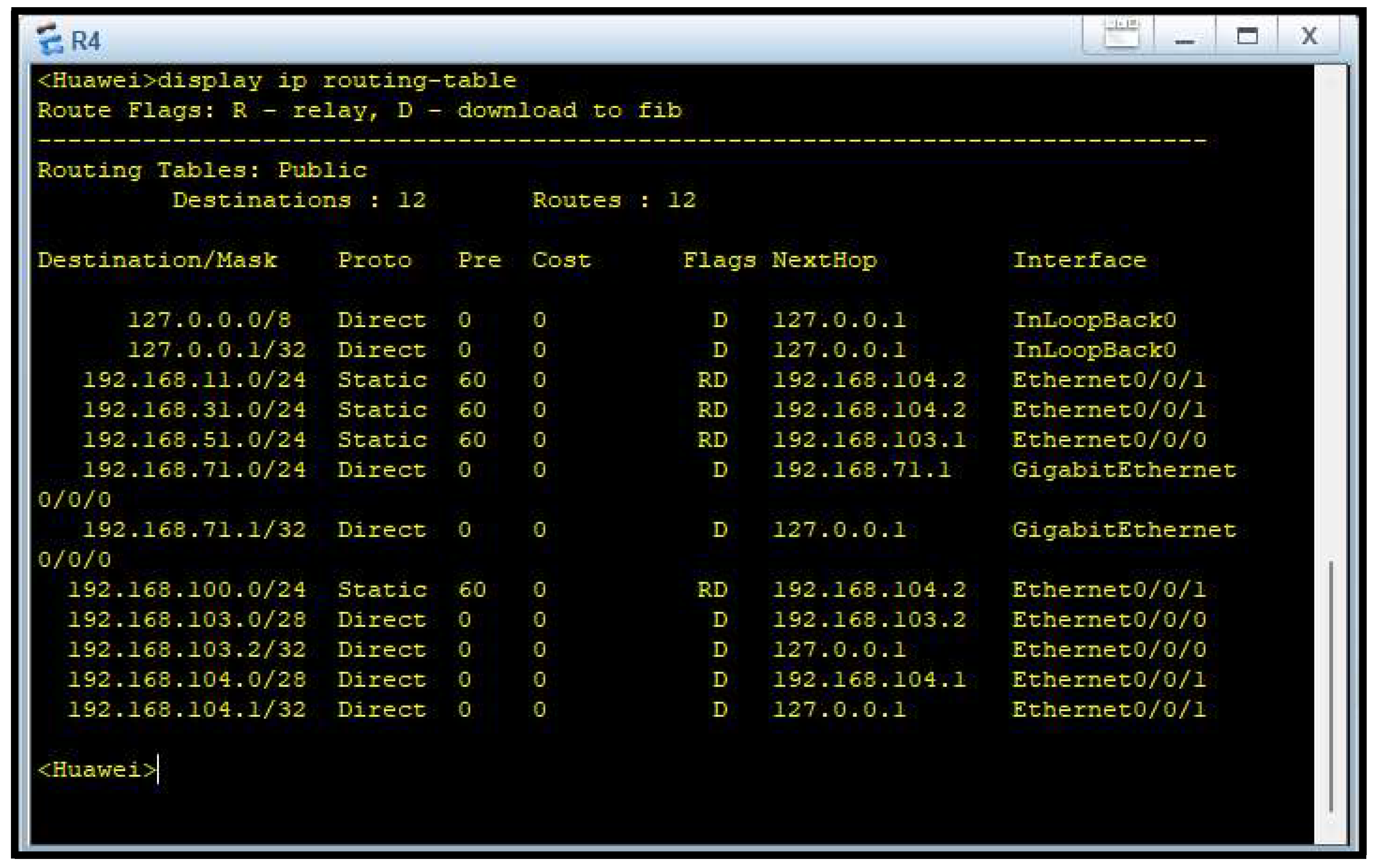
Figure 8.
Ring Topology.
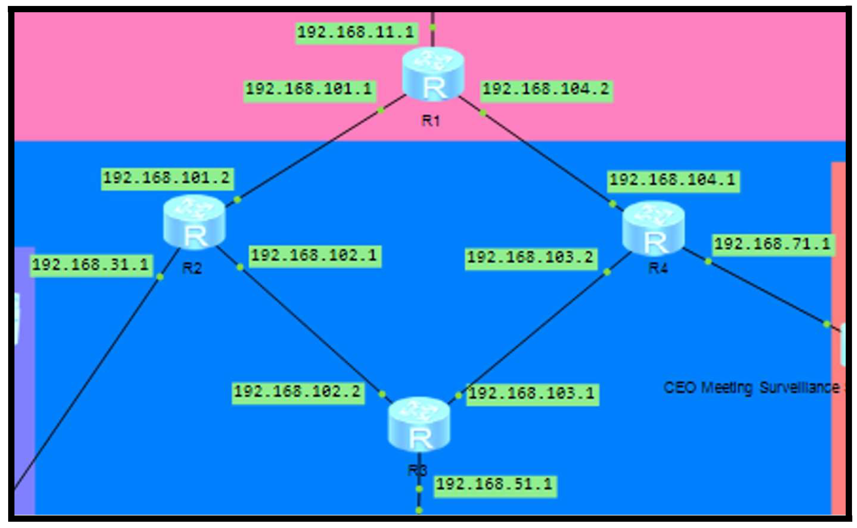
Figure 9.
IPv4 Subnet mask table (TheNetworkSeal.wordpress.com, 2016).
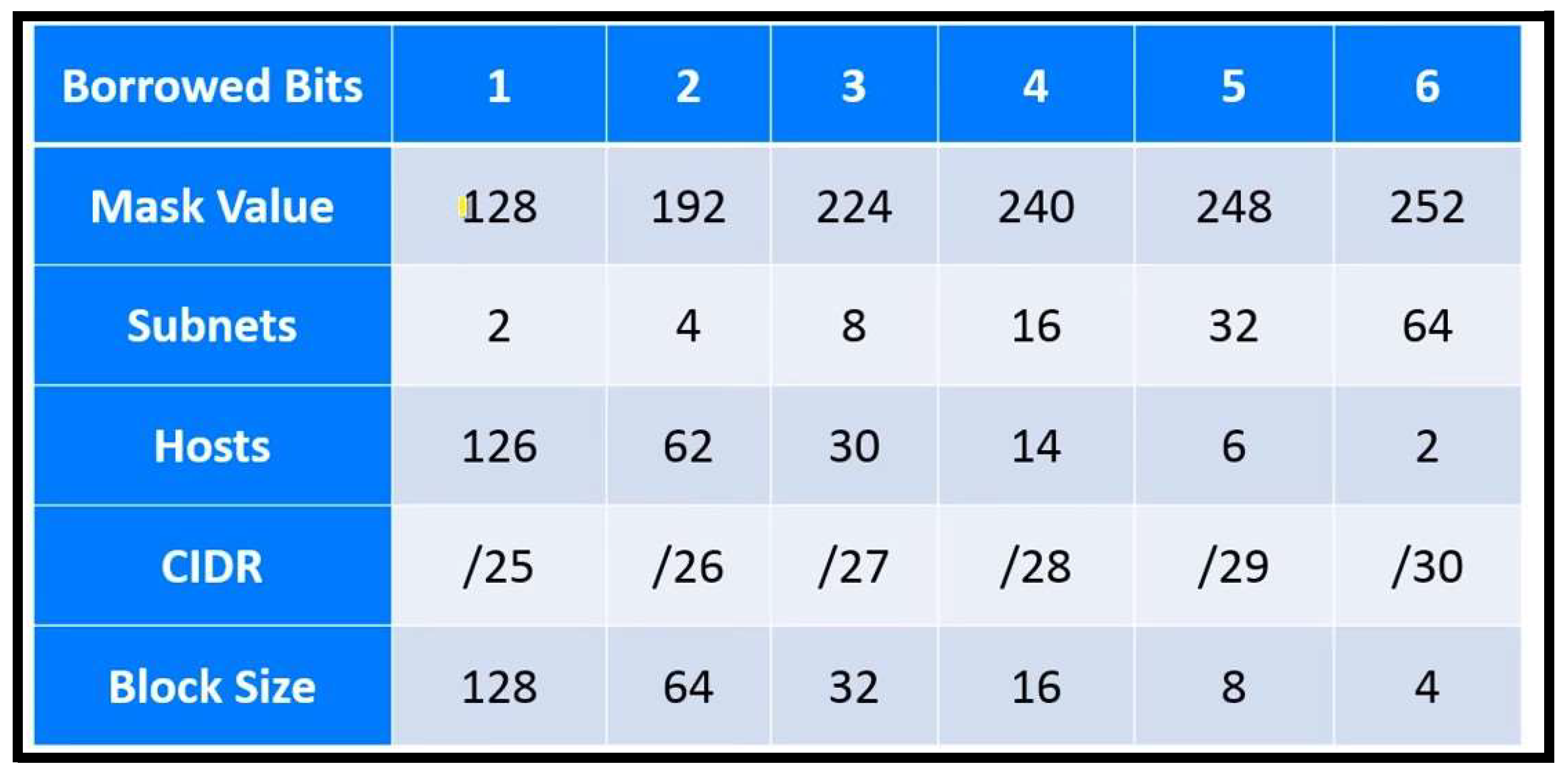

Table 1.
IP Addressing Table.
| Floor | Switch | Area | Num. of Host | Network ID | Valid Host ID | Broadcast ID | Subnet Mask |
|---|---|---|---|---|---|---|---|
| Floor 1 |
Printing and Server |
Printing Room and Server Room |
255 | 192.168.11.0 | 192.168.11.1 - 192.168.11.254 |
192.168.11.2 55 |
255.255.255.0 |
| Floor 2 | Finance and Sales | Finance and Sales Department | 255 | 192.168.31.0 | 192.168.31.1 - 192.168.31.254 |
192.168.31.2 55 |
255.255.255.0 |
| CS and IT | CS and IT Department | 255 | 192.168.51.0 | 192.168.51.1 - 192.168.51.254 |
192.168.51.2 55 |
255.255.255.0 | |
| Others |
CEO’s Room, Meeting Room, Staff Pantry, Surveillance Room |
255 | 192.168.71.0 | 192.168.71.1 - 192.168.71.254 |
192.168.71.2 55 |
255.255.255.0 |
Table 2.
Departments and Switches.
| Switch | Device | IP Address | Default Gateway |
|---|---|---|---|
| 1 - Printing and Server | AP-1 | 192.168.11.20–250 | 192.168.11.1 |
| Printer-1 | 192.168.11.11 | ||
| Printer-2 | 192.168.11.12 | ||
| CCTV-1 | 192.168.11.13 | ||
| Server-1 | 192.168.11.14 | ||
| Server-2 | 192.168.11.15 | ||
| Server-3 | 192.168.11.16 | ||
| Server-4 | 192.168.11.17 | ||
| Server-5 | 192.168.11.18 | ||
| CCTV-2 | 192.168.11.19 | ||
| 2—Finance and Sales | CCTV-3 | 192.168.31.12 | 192.168.31.1 |
| Printer-3 | 192.168.31.11 | ||
| PC-1 | 192.168.31.13 | ||
| PC-2 | 192.168.31.14 | ||
| PC-3 | 192.168.31.15 | ||
| PC-4 | 192.168.31.16 | ||
| PC-5 | 192.168.31.17 | ||
| PC-6 | 192.168.31.18 | ||
| PC-7 | 192.168.31.19 | ||
| PC-8 | 192.168.31.20 | ||
| PC-9 | 192.168.31.21 | ||
| PC-10 | 192.168.31.22 | ||
| PC-11 | 192.168.31.23 | ||
| PC-12 | 192.168.31.24 | ||
| PC-13 | 192.168.31.25 | ||
| PC-14 | 192.168.31.26 | ||
| Printer-4 | 192.168.31.27 | ||
| CCTV-4 | 192.168.31.28 | ||
| 3—Customer Service and IT | PC-15 | 192.168.51.13 | 192.168.51.1 |
| PC-16 | 192.168.51.14 | ||
| PC-17 | 192.168.51.15 | ||
| PC-18 | 192.168.51.16 | ||
| PC-19 | 192.168.51.17 | ||
| PC-20 | 192.168.51.18 | ||
| PC-21 | 192.168.51.19 | ||
| PC-22 | 192.168.51.21 | ||
| PC-23 | 192.168.51.22 | ||
| PC-24 | 192.168.51.23 | ||
| PC-25 | 192.168.51.24 | ||
| PC-26 | 192.168.51.25 | ||
| PC-27 | 192.168.51.26 | ||
| PC-28 | 192.168.51.27 | ||
| CCTV-5 | 192.168.51.12 | ||
| CCTV-6 | 192.168.51.20 | ||
| Printer-5 | 192.168.51.11 | ||
| Printer-6 | 192.168.51.28 | ||
| 4—CEO, Meeting, Surveillance | PC-29 | 192.168.71.11 | 192.168.71.1 |
| PC-30 | 192.168.71.15 | ||
| AP-2 | 192.168.71.17–250 | ||
| CCTV-7 | 192.168.71.12 | ||
| CCTV-8 | 192.168.71.13 | ||
| CCTV-9 | 192.168.71.14 | ||
| CCTV-10 | 192.168.71.16 |
Disclaimer/Publisher’s Note: The statements, opinions and data contained in all publications are solely those of the individual author(s) and contributor(s) and not of MDPI and/or the editor(s). MDPI and/or the editor(s) disclaim responsibility for any injury to people or property resulting from any ideas, methods, instructions or products referred to in the content. |
© 2025 by the authors. Licensee MDPI, Basel, Switzerland. This article is an open access article distributed under the terms and conditions of the Creative Commons Attribution (CC BY) license (http://creativecommons.org/licenses/by/4.0/).
Copyright: This open access article is published under a Creative Commons CC BY 4.0 license, which permit the free download, distribution, and reuse, provided that the author and preprint are cited in any reuse.


