Submitted:
11 January 2023
Posted:
11 January 2023
You are already at the latest version
Abstract
Keywords:
1. Introduction and background
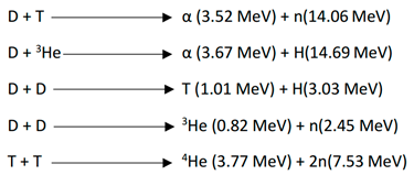
2. Bubble

3. Self-interstitial solid solution strengthening – crystallography of plasma facing materials


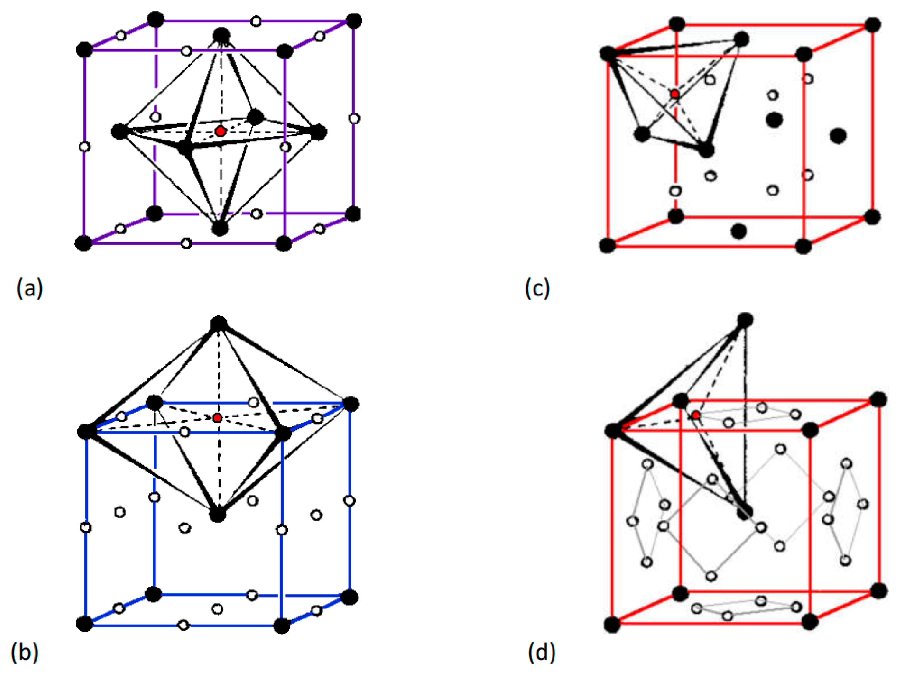

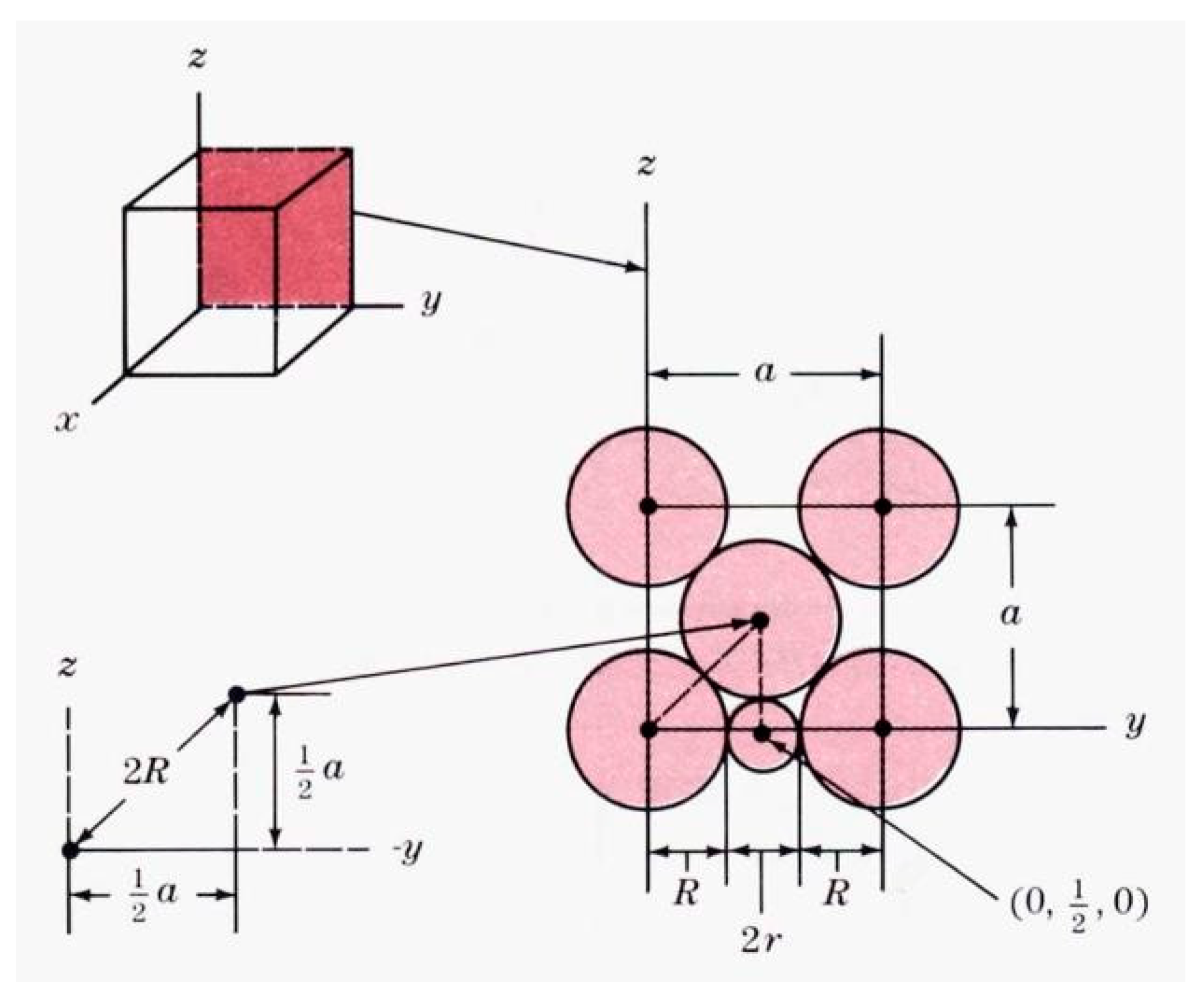
4. Size of interstitial sites in a lattice - Largest interstitial void radius in fcc lattice
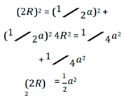
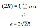


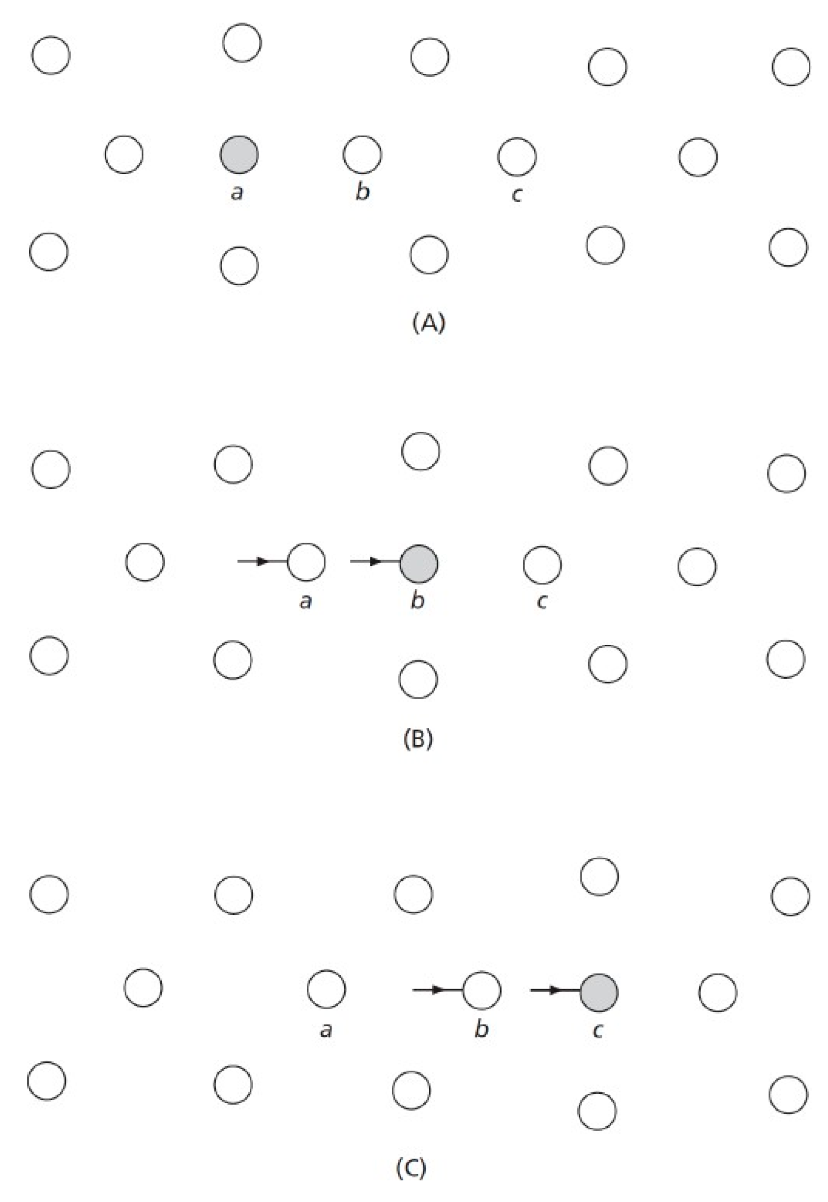
5. Self-diffusion coefficient
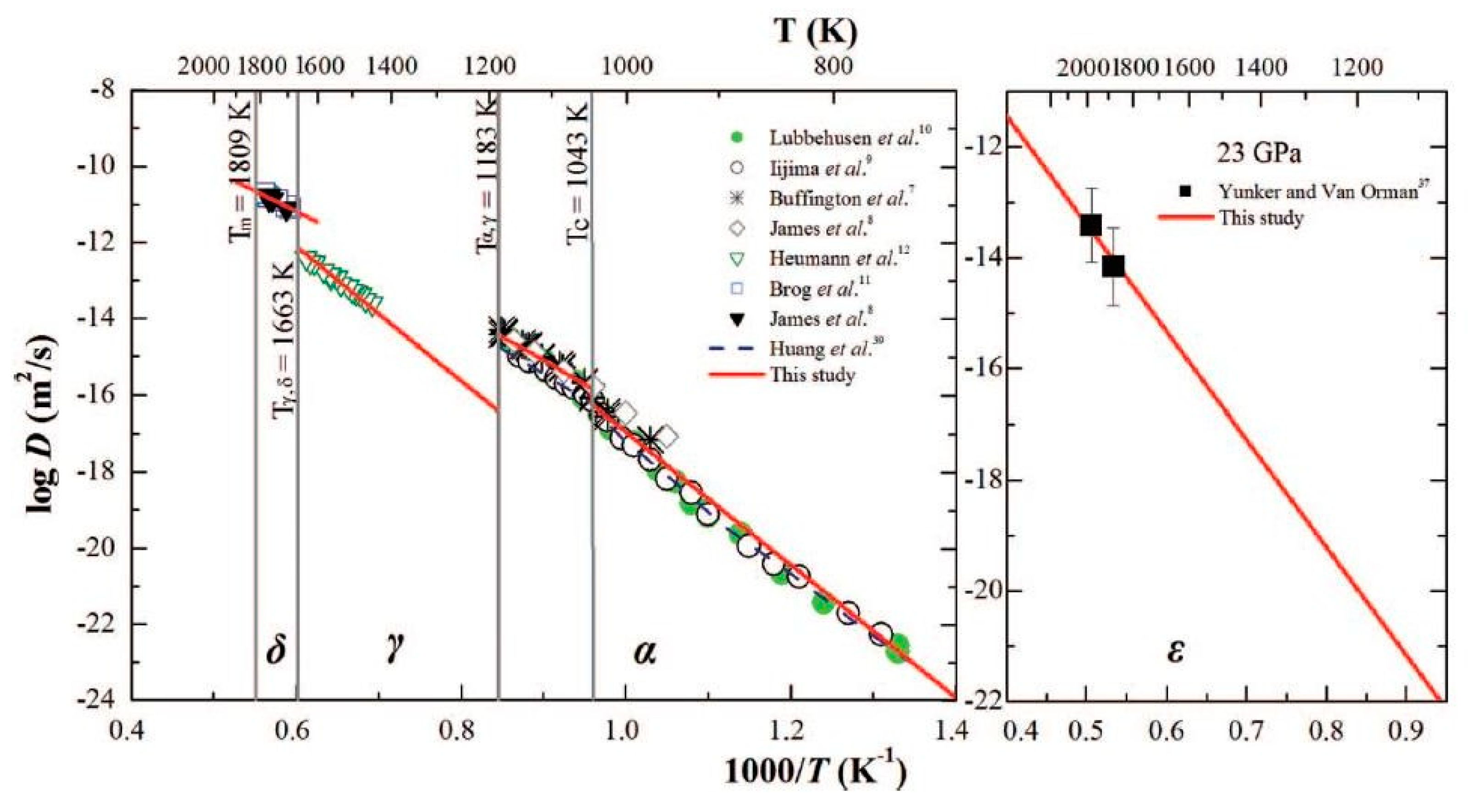
6. Other plasma facing materials and conditions
- 1)
- Tritium (2H1) is retained in crystal lattice of Carbon hexagonal close packed structure.
- 2)
- This result in 2H1 rich inventory.
7. Manufacturing, processing, and characterization
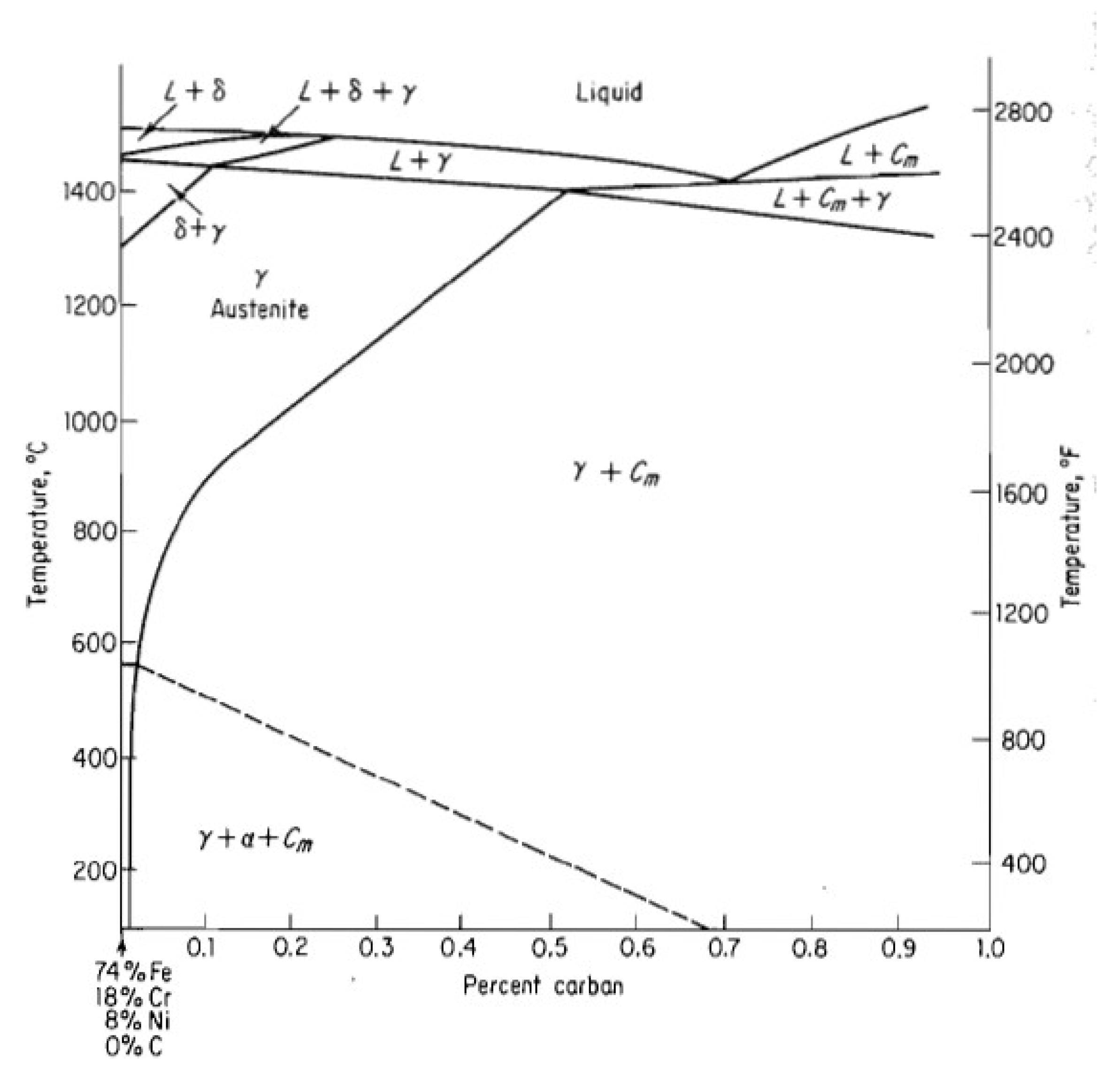
7.1. Phase diagram
| Alloy | Designation | C | N | Cr | Ni | Mo | Mn | Si | Other | Other | Other |
| 321 | S32100 | 0.05 | 0.01 | 17.7 | 9.1 | 0.03 | 1.0 | 0.45 | 0.001S | 0.03P | 0.4 Ti |
7.2. Heat treatment

7.3. Characterization
8. Conclusion
- Bubble is identified as crystal lattice (point) defect – not a physical / geometric feature.
- A crystal lattice having the tendency to form self-interstitial solid solution has been identified.
- FCC lattice γ – iron is identified as suitable crystal lattice.
- Insertion of Fe (0.129 nm) in interstitial site (0.053 nm) will form interstitial solid solution with large lattice strain.
- 321 Stainless steel is proposed as suitable material.
- Co base superalloy is presented as second choice.
References
- Rubel, M. ; Fusion Neutrons: Tritium Breeding and Impact on Wall Materials and Components of Diagnostic Systems. Journal of Fusion Energy 2019, 38, 315–329. [Google Scholar] [CrossRef]
- Abdou, M.; et al. Recent progress in design studies for tokamak demonstration and commercial power plants. In Fusion Reactor Design and Technology; International Atomic Energy Agency Vienna 1983; pp. 231-272.
- Bachmann, C.; et al. Initial DEMO tokamak design configuration studies. Fusion Engineering and Design 2015, 98–99, 1423–1426. [Google Scholar] [CrossRef]
- Brown, R. and M. Porton. The development of a methodology to allocate RAMI requirements to DEMO: The development of design tools & methodologies for DEMO in Europe. in 2013 IEEE 25th Symposium on Fusion Engineering (SOFE). 2013.
- Chen, H.; et al. Magnetohydrodynamic experimental design and program for Chinese liquid metal LiPb experimental loop DRAGON-IV. Fusion Engineering and Design 2010, 85, 1742–1746. [Google Scholar] [CrossRef]
- Enoeda, M.; et al. Design and technology development of solid breeder blanket cooled by supercritical water in Japan. Nuclear Fusion 2003, 43, 1837–1844. [Google Scholar] [CrossRef]
- Federici, G.; et al. DEMO design activity in Europe: Progress and updates. Fusion Engineering and Design 2018, 136, 729–741. [Google Scholar] [CrossRef]
- Federici, G.; et al. An overview of the EU breeding blanket design strategy as an integral part of the DEMO design effort. Fusion Engineering and Design 2019, 141, 30–42. [Google Scholar] [CrossRef]
- Federici, G.; et al. Overview of EU DEMO design and R&D activities. Fusion Engineering and Design 2014, 89, 882–889. [Google Scholar]
- Hirai, T.; et al. ITER tungsten divertor design development and qualification program. Fusion Engineering and Design 2013, 88, 1798–1801. [Google Scholar] [CrossRef]
- Ho, S.K. and M.A. Abdou, Exploration and assesment of design windows for a Tokamak-based volumetric neutron source. Fusion Engineering and Design 1996, 31, 323–332. [CrossRef]
- Igitkhanov, Y.; R. Fetzer, and B. Bazylev, Effect of design geometry of the demo first wall on the plasma heat load. Nuclear Materials and Energy 2016, 9, 560–564. [CrossRef]
- Konishi, S.; S. Nishio, and K. Tobita, DEMO plant design beyond ITER. Fusion Engineering and Design 2002, 63–64, 11–17.
- Lei, M.; et al. Design and thermal-hydraulic evaluation of helium-cooled ceramic breeder blanket for China fusion engineering test reactor. International Journal of Energy Research 2018, 42, 1657–1663. [Google Scholar] [CrossRef]
- Leshukov, A.Y.; et al. Design development and analytical assessment of LLCB TBM in Russian Federation during 2012–2013. Fusion Engineering and Design 2014, 89, 1232–1240. [Google Scholar] [CrossRef]
- Lister, J.B.; et al. The ITER CODAC conceptual design. Fusion Engineering and Design 2007, 82, 1167–1173. [Google Scholar] [CrossRef]
- Mitteau, R.; et al. Heat loads and shape design of the ITER first wall. Fusion Engineering and Design 2010, 85, 2049–2053. [Google Scholar] [CrossRef]
- Moeslang, A.; et al. The IFMIF test facilities design. Fusion Engineering and Design 2006, 81, 863–871. [Google Scholar] [CrossRef]
- Moscato, I.; et al. Preliminary design of EU DEMO helium-cooled breeding blanket primary heat transfer system. Fusion Engineering and Design 2018, 136, 1567–1571. [Google Scholar] [CrossRef]
- Norajitra, P.; et al. Conceptual design of the dual-coolant blanket in the frame of the EU power plant conceptual study. Fusion Engineering and Design 2003, 69, 669–673. [Google Scholar] [CrossRef]
- Perrault, D. ; Safety issues to be taken into account in designing future nuclear fusion facilities. Fusion Engineering and Design 2016, 109–111, 1733–1738. [Google Scholar] [CrossRef]
- Petti, D.A.; et al. ARIES-AT safety design and analysis. Fusion Engineering and Design 2006, 80, 111–137. [Google Scholar] [CrossRef]
- Pitts, R.A.; et al. Physics basis and design of the ITER plasma-facing components. Journal of Nuclear Materials 2011, 415 (Supplement 1), S957–S964. [Google Scholar] [CrossRef]
- Pitts, R.A.; et al. A full tungsten divertor for ITER: Physics issues and design status. Journal of Nuclear Materials 2013, 438, S48–S56. [Google Scholar] [CrossRef]
- Rampal, G.; et al. HCLL TBM for ITER-design studies. Fusion Engineering and Design 2005, 75–79, 917–922. [Google Scholar] [CrossRef]
- Sagara, A.; et al. Innovative Liquid Breeder Blanket Design Activities in Japan. Fusion Science and Technology 2005, 47, 524–529. [Google Scholar] [CrossRef]
- Seki, Y. ; Fusion reactor design and technology program in Japan. Fusion Engineering and Design 1994, 25, 49–66. [Google Scholar] [CrossRef]
- Sergeev, V.Y.; et al. Conceptual design of divertor and first wall for DEMO-FNS. Nuclear Fusion 2015, 55, 123013. [Google Scholar] [CrossRef]
- Song, Y.T.; et al. Concept Design of CFETR Tokamak Machine. IEEE Transactions on Plasma Science 2014, 42, 503–509. [Google Scholar] [CrossRef]
- Tillack, M.S.; et al. Configuration and engineering design of the ARIES-RS tokamak power plant. Fusion Engineering and Design 1997, 38, 87–113. [Google Scholar] [CrossRef]
- Tobita, K.; G. Federici, and K. Okano, Research and development status on fusion DEMO reactor design under the Broader Approach. Fusion Engineering and Design 2014, 89, 1870–1874. [CrossRef]
- Tobita, K.; et al. Design study of fusion DEMO plant at JAERI. Fusion Engineering and Design 2006, 81, 1151–1158. [Google Scholar] [CrossRef]
- Voss, G.M.; et al. Conceptual design of a component test facility based on the spherical tokamak. Fusion Engineering and Design 2008, 83, 1648–1653. [Google Scholar] [CrossRef]
- Wan, B.; et al. Physics Design of CFETR: Determination of the Device Engineering Parameters. IEEE Transactions on Plasma Science 2014, 42, 495–502. [Google Scholar] [CrossRef]
- Wu, Y. ; Design status and development strategy of China liquid lithium–lead blankets and related material technology. Journal of Nuclear Materials 2007, 367–370, 1410–1415. [Google Scholar] [CrossRef]
- You, J.H.; et al. European DEMO divertor target: Operational requirements and material-design interface. Nuclear Materials and Energy 2016, 9, 71–176. [Google Scholar] [CrossRef]
- Zheng, J.; et al. Concept design of CFETR superconducting magnet system based on different maintenance ports. Fusion Engineering and Design 2013, 88, 2960–2966. [Google Scholar] [CrossRef]
- Zheng, J.; et al. Concept design of hybrid superconducting magnet for CFETR Tokamak reactor. In 2013 IEEE 25th Symposium on Fusion Engineering (SOFE). 2013.
- Zhuang, G.; et al. Progress of the CFETR design. Nuclear Fusion 2019, 59, 112010. [Google Scholar] [CrossRef]
- Valles, G.; et al. Temperature dependence of underdense nanostructure formation in tungsten under helium irradiation. Journal of Nuclear Materials 2017, 490, 08–114. [Google Scholar] [CrossRef]
- Ying, A.Y. and A.A. Gaizer, The effects of imperfect insulator coatings on MHD and heat transfer in rectangular ducts. Fusion Engineering and Design 1995, 27, 634–641. [CrossRef]
- Ying, A.Y. and M.A. Abdou, Application of reliability analysis method to fusion component testing. Fusion Engineering and Design 1995, 27, 191–197. [CrossRef]
- You, J.H. and M. Miskiewicz, Material parameters of copper and CuCrZr alloy for cyclic plasticity at elevated temperatures. Journal of Nuclear Materials 2008, 373, 269–274. [CrossRef]
- Wurster, S.; et al. Fracture behaviour of tungsten–vanadium and tungsten–tantalum alloys and composites. Journal of Nuclear Materials 2011, 413, 166–176. [Google Scholar] [CrossRef]
- Zinkle, S.J. and J.T. Busby, Structural materials for fission & fusion energy. Materials Today 2009, 12, 12–19.
- Young, G.A.; et al. Welds for Nuclear Systems☆, in Reference Module in Materials Science and Materials Engineering. 2019, Elsevier.
- Zenobia, S.J.; L.M. Garrison, and G.L. Kulcinski, The response of polycrystalline tungsten to 30keV helium ion implantation at normal incidence and high temperatures. Journal of Nuclear Materials 2012, 425, 83–92. [CrossRef]
- Yoshida, N.; et al. Impact of low energy helium irradiation on plasma facing metals. Journal of Nuclear Materials 2005, 337–339, 946–950. [Google Scholar] [CrossRef]
- Yi, X.; et al. A study of helium bubble production in 10keV He+ irradiated tungsten. Fusion Engineering and Design 2017, 125, 454–457. [Google Scholar] [CrossRef]
- Yin, H.; et al. Recent studies of tungsten-based plasma-facing materials in the linear plasma device STEP. Tungsten 2019, 1, 132–140. [Google Scholar] [CrossRef]
- Khan, A.; et al. Effect of rhenium addition on tungsten fuzz formation in helium plasmas. Journal of Nuclear Materials 2016, 474, 99–104. [Google Scholar] [CrossRef]
- Gai, X.; et al. Helium bubbles in bcc Fe and their interactions with irradiation. Journal of Nuclear Materials 2015, 462, 382–390. [Google Scholar] [CrossRef]
- Xu, C. and W. Wang, Simulation Study of Helium Effect on the Microstructure of Nanocrystalline Body-Centered Cubic Iron. Materials 2019, 12. [Google Scholar]
- Novakowski, T.J.; J.K. Tripathi, and A. Hassanein, Effect of high-flux, low-energy He+ ion irradiation on Ta as a plasma-facing material. Scientific Reports 2016, 6, 39746. [CrossRef]
- Dias, M.; et al. Helium and deuterium irradiation effects in W-Ta composites produced by pulse plasma compaction. Journal of Nuclear Materials 2017, 492, 105–112. [Google Scholar] [CrossRef]
- Kajita, S.; et al. Fuzzy nanostructure growth on Ta/Fe by He plasma irradiation. Scientific Reports 2016, 6, 30380. [Google Scholar] [CrossRef]
- Fiflis, P.; et al. Nanostructuring of Palladium with Low-Temperature Helium Plasma. Nanomaterials 2015, 5. [Google Scholar] [CrossRef]
- Fan, C.; et al. Dual Beam In Situ Radiation Studies of Nanocrystalline Cu. Materials 2019, 12. [Google Scholar] [CrossRef]
- Su, Q.; et al. Resistance to Helium Bubble Formation in Amorphous SiOC/Crystalline Fe Nanocomposite. Materials 5, 12. [Google Scholar] [CrossRef] [PubMed]
- Yang, X.; et al. Tungsten–potassium: a promising plasma-facing material. Tungsten 2019, 1, 141–158. [Google Scholar] [CrossRef]
- van der Schaaf, B.; et al. The development of EUROFER reduced activation steel. Fusion Engineering and Design 2003, 69, 197–203. [Google Scholar] [CrossRef]
- Tan, L.; et al. Development of nanoprecipitates-strengthened advanced ferritic alloys for nuclear reactor applications. 2019: United States.
- Tavassoli, A.A.F.; et al. Current status and recent research achievements in ferritic/martensitic steels. Journal of Nuclear Materials 2014, 455, 269–276. [Google Scholar] [CrossRef]
- Reimann, J.; et al. Thermomechanics of solid breeder and Be pebble bed materials. Fusion Engineering and Design 2002, 61–62, 319–331. [Google Scholar] [CrossRef]
- van Til, S.; et al. Evolution of beryllium pebbles (HIDOBE) in long term, high flux irradiation in the high flux reactor. Fusion Engineering and Design 2011, 86, 2258–2261. [Google Scholar] [CrossRef]
- Zhang, C.; A. Ying, and M.A. Abdou, FEM Modeling of Pebble Bed/Structural Wall Separation. Fusion Science and Technology 2015, 68, 612–617. [CrossRef]
- Ying, A.; et al. Status of ceramic breeder pebble bed thermo-mechanics R&D and impact on breeder material mechanical strength. Fusion Engineering and Design 2012, 87, 1130–1137. [Google Scholar]
- Fedorov, A.V.; et al. Post irradiation characterization of beryllium and beryllides after high temperature irradiation up to 3000appm helium production in HIDOBE-01. Fusion Engineering and Design 2016, 102, 74–80. [Google Scholar] [CrossRef]
- Snead, L.L.; T.D. Burchell, and Y. Katoh, Swelling of nuclear graphite and high quality carbon fiber composite under very high irradiation temperature. Journal of Nuclear Materials 2008, 381, 55–61. [CrossRef]
- Brooks, J.N.; et al. Plasma-facing material alternatives to tungsten. Nuclear Fusion 2015, 55. [Google Scholar] [CrossRef]
- Rowcliffe, A.F.; et al. Materials-engineering challenges for the fusion core and lifetime components of the fusion nuclear science facility. Nuclear Materials and Energy 2018, 16, 82–87. [Google Scholar] [CrossRef]
- Odette, G.R.; M.J. Alinger, and B.D. Wirth, Recent Developments in Irradiation-Resistant Steels. Annual Review of Materials Research 2008, 38, 471–503. [CrossRef]
- Mansur, L.K.; et al. Control of helium effects in irradiated materials based on theory and experiment. Journal of Nuclear Materials 1986, 141–143, 633–646. [Google Scholar] [CrossRef]
- Beyerlein, I.J.; et al. Radiation damage tolerant nanomaterials. Materials Today 2013, 16, 443–449. [Google Scholar] [CrossRef]
- Bauer, J.; et al. Influence of near-surface blisters on deuterium transport in tungsten. Nuclear Fusion 2017, 57, 086015. [Google Scholar] [CrossRef]
- Chen, W.Q.; et al. Irradiation hardening induced by blistering in tungsten due to low-energy high flux hydrogen plasma exposure. Journal of Nuclear Materials 2019, 522, 11–18. [Google Scholar] [CrossRef]
- Gavish Segev, I.; et al. Hydrogen blister formation in single crystal and polycrystalline tungsten irradiated by MeV protons. Journal of Nuclear Materials 2019, 513, 209–220. [Google Scholar] [CrossRef]
- Zhou, H.-B.; et al. Towards suppressing H blistering by investigating the physical origin of the H– He interaction in W. Nuclear Fusion 2010, 50, 115010. [Google Scholar] [CrossRef]
- Baldwin, M.J. and R.P. Doerner, Formation of helium induced nanostructure ‘fuzz’ on various tungsten grades. Journal of Nuclear Materials 2010, 404, 165–173. [CrossRef]
- Dasgupta, D.; et al. On the origin of ‘fuzz’ formation in plasma-facing materials. Nuclear Fusion 2019, 59, 086057. [Google Scholar] [CrossRef]
- Doerner, R.P.; M.J. Baldwin, and P.C. Stangeby, An equilibrium model for tungsten fuzz in an eroding plasma environment. Nuclear Fusion 2011, 51, 043001. [CrossRef]
- Doerner, R.P.; et al. Motion of W and He atoms during formation of W fuzz. Nuclear Fusion 2018, 58, 066005. [Google Scholar] [CrossRef]
- Chen, D.; et al. Self-organization of helium precipitates into elongated channels within metal nanolayers. Science Advances 2017, 3, eaao2710. [Google Scholar] [CrossRef]
- Dechaumphai, E.; et al. Near-surface thermal characterization of plasma facing components using the 3-omega method. Journal of Nuclear Materials 2014, 455, 56–60. [Google Scholar] [CrossRef]
- Huang, S.; Y. Zhao, and W. Wang, Numerical Evaluation on Heat Shock Resistance of Two ITER-Like First Wall Mockups. Journal of Fusion Energy 2015, 34, 1465–1477. [CrossRef]
- Zhang, F.; et al. Swelling and Helium Bubble Morphology in a Cryogenically Treated FeCrNi Alloy with Martensitic Transformation and Reversion after Helium Implantation. Materials 2019, 12. [Google Scholar] [CrossRef]
- Lukacs, M. and L.G. Williams, Nuclear safety issues for fusion power plants. Fusion Engineering and Design 2020, 150, 111377. [CrossRef]
- Perez, D.; et al. The mobility of small vacancy/helium complexes in tungsten and its impact on retention in fusion-relevant conditions. Scientific Reports 2017, 7, 2522. [Google Scholar] [CrossRef] [PubMed]
- Sandoval, L.; et al. An Overview of Recent Standard and Accelerated Molecular Dynamics Simulations of Helium Behavior in Tungsten. Materials 2019, 12. [Google Scholar] [CrossRef] [PubMed]
- Taylor, C.A.; et al. Investigating Helium Bubble Nucleation and Growth through Simultaneous In- Situ Cryogenic, Ion Implantation, and Environmental Transmission Electron Microscopy. Materials 2019, 12. [Google Scholar] [CrossRef] [PubMed]
- Wang, K.; et al. Morphologies of tungsten nanotendrils grown under helium exposure. Scientific Reports 2017, 7, 42315. [Google Scholar] [CrossRef] [PubMed]
- Li, X.-C.; et al. Helium defects interactions and mechanism of helium bubble growth in tungsten: A molecular dynamics simulation. Journal of Nuclear Materials 2014, 451, 356–360. [Google Scholar] [CrossRef]
- Kim, I.S.; et al. Defect and void evolution in oxide dispersion strengthened ferritic steels under 3.2 MeV Fe+ ion irradiation with simultaneous helium injection. Journal of Nuclear Materials 2000, 280, 264–274. [Google Scholar] [CrossRef]
- Trinkaus, H. and B.N. Singh, Helium accumulation in metals during irradiation – where do we stand? Journal of Nuclear Materials 2003, 323, 229–242. [CrossRef]
- Kajita, S.; et al. Growth of multifractal tungsten nanostructure by He bubble induced directional swelling. New Journal of Physics 2015, 17, 043038. [Google Scholar] [CrossRef]
- Abernethy, R.G. ; Predicting the performance of tungsten in a fusion environment: a literature review. Materials Science and Technology 2017, 33, 388–399. [Google Scholar] [CrossRef]
- Linke, J.; et al. Challenges for plasma-facing components in nuclear fusion. Matter and Radiation at Extremes 2019, 4, 056201. [Google Scholar] [CrossRef]
- Yang, Q.; et al. Nanostructured fuzz growth on tungsten under low-energy and high-flux He irradiation. Scientific Reports 2015, 5, 10959. [Google Scholar] [CrossRef] [PubMed]
- Wang, Y. and K. Hattar, Special Issue: Radiation Damage in Materials-Helium Effects. Materials 2020, 13.
- Smallman, R.E. and R.J. Bishop, Modern Physical Metallurgy and Materials Engineering. 1999: Elsevier Science.
- Dieter, G.E. and D. Bacon, Mechanical Metallurgy. 1988: McGraw-Hill.
- Takamura, S.; et al. Formation of Nanostructured Tungsten with Arborescent Shape due to Helium Plasma Irradiation. Plasma and Fusion Research 2006, 1, 051–051. [Google Scholar] [CrossRef]
- Zhang, N.; et al. Trapping of helium atom by vacancy in tungsten: a density functional theory study. The European Physical Journal B 2017, 90, 101. [Google Scholar] [CrossRef]
- Yang, Y.; et al. Roles of vacancy/interstitial diffusion and segregation in the microchemistry at grain boundaries of irradiated Fe–Cr–Ni alloys. Journal of Nuclear Materials 2016, 473, 35–53. [Google Scholar] [CrossRef]
- Yang, L. and B.D. Wirth, Energetics of hydrogen and helium-vacancy complexes in bulk and near surfaces of tungsten: First-principles study. Journal of Applied Physics 2018, 123, 215104. [CrossRef]
- Wu, X.; et al. First principles study of helium trapping by solute elements in tungsten. Journal of Nuclear Materials 2014, 455, 151–156. [Google Scholar] [CrossRef]
- Nakashima, K.; R.E. Stoller, and H. Xu, Recombination radius of a Frenkel pair and capture radius of a self-interstitial atom by vacancy clusters in bcc Fe. Journal of Physics: Condensed Matter 2015, 27, 335401.
- Van Brutzel, L.; A. Chartier, and J.P. Crocombette, Basic mechanisms of Frenkel pair recombinations in ${\text{UO}}_{2}$ fluorite structure calculated by molecular dynamics simulations. Physical Review B 2008, 78, 024111. [CrossRef]
- van Gog, H. and M.A. van Huis, Structural and Electronic Properties of Frenkel and Schottky Defects at the MgO{100} Surface: Spin Polarization, Mid-Band Gap States, and Charge Trapping at Vacancy Sites. The Journal of Physical Chemistry C 2019, 123, 14408–14420. [CrossRef]
- Dubinko, V.I. Radiation damage and recovery of crystals:Frenkel vs. Schottky defect production. arXiv 2014, arXiv:arXiv:1406.4318. [Google Scholar]
- Frenkel, J. ; Über die Wärmebewegung in festen und flüssigen Körpern. Zeitschrift für Physik 1926, 35, 652–669. [Google Scholar] [CrossRef]
- Miyamoto, M.; et al. In situtransmission electron microscope observation of the formation of fuzzy structures on tungsten. Physica Scripta 2014, T159, 014028. [Google Scholar] [CrossRef]
- Hwangbo, D.; et al. Growth process of nano-tendril bundles with sputtered tungsten. Nuclear Materials and Energy 2019, 18, 250–257. [Google Scholar] [CrossRef]
- Wright, G.M.; et al. Comparison of tungsten nano-tendrils grown in Alcator C-Mod and linear plasma devices. Journal of Nuclear Materials 2013, 438, S84–S89. [Google Scholar] [CrossRef]
- Wright, G.M.; et al. Tungsten nano-tendril growth in the Alcator C-Mod divertor. Nuclear Fusion 2012, 52, 042003. [Google Scholar] [CrossRef]
- Kajita, S.; et al. Enhanced growth of large-scale nanostructures with metallic ion precipitation in helium plasmas. Scientific Reports 2018, 8, 56. [Google Scholar] [CrossRef]
- El Atwani, O.; et al. In-Situ Helium Implantation and TEM Investigation of Radiation Tolerance to Helium Bubble Damage in Equiaxed Nanocrystalline Tungsten and Ultrafine Tungsten-TiC Alloy. Materials 2020, 13. [Google Scholar] [CrossRef]
- Kong, X.-S.; et al. The role of impurity oxygen in hydrogen bubble nucleation in tungsten. Journal of Nuclear Materials 2013, 433, 357–363. [Google Scholar] [CrossRef]
- López-Ruiz, P.; et al. Powder metallurgical processing of self-passivating tungsten alloys for fusion first wall application. Journal of Nuclear Materials 2013, 442 (Supplement. 1), S219–S224. [Google Scholar] [CrossRef]
- Yamagiwa, M.; et al. Helium bubble formation on tungsten in dependence of fabrication method. Journal of Nuclear Materials 2011, 417, 499–503. [Google Scholar] [CrossRef]
- Bakaev, A.; et al. Ab initio study of interaction of helium with edge and screw dislocations in tungsten. Nuclear Instruments and Methods in Physics Research Section B: Beam Interactions with Materials and Atoms 2017, 393, 150–154. [Google Scholar] [CrossRef]
- Abdou, M.; et al. Blanket/first wall challenges and required R&D on the pathway to DEMO. Fusion Engineering and Design 2015, 100, 2–43. [Google Scholar]
- Beckers, M.; et al. Investigations of the first-wall erosion of DEMO with the CELLSOR code. Nuclear Materials and Energy 2017, 12, 1163–1170. [Google Scholar] [CrossRef]
- Clinard Jr, F.W.; First wall materials problems in fusion reactors. 1974, Los Alamos Scientific Lab.; N. Mex.(USA).
- Huang, Y.; M.S. Tillack, and N.M. Ghoniem, Tungsten monoblock concepts for the Fusion Nuclear Science Facility (FNSF) first wall and divertor. Fusion Engineering and Design 2018, 135, 346–355. [CrossRef]
- Linsmeier, C.; et al. Advanced first wall and heat sink materials. in 1st IAEA DEMO Programme Workshop. 2012.
- Litnovsky, A.; et al. Smart tungsten alloys as a material for the first wall of a future fusion power plant. Nuclear Fusion 2017, 57, 066020. [Google Scholar] [CrossRef]
- Litnovsky, A.; et al. Smart alloys for a future fusion power plant: First studies under stationary plasma load and in accidental conditions. Nuclear Materials and Energy 2017, 12, 1363–1367. [Google Scholar] [CrossRef]
- Matthews, G.F. ; Plasma operation with an all metal first-wall: Comparison of an ITER-like wall with a carbon wall in JET. Journal of Nuclear Materials 2013, 438, S2–S10. [Google Scholar] [CrossRef]
- Orient, G.; P. Gierszewski, and J. Garner, Elastic-plastic analysis of slender first wall structures. Fusion Technology 1985, 8, 586–591. [CrossRef]
- Pestchanyi, S. Simulation of Heat Flux to the DEMO First Wall Due to Filamentary Transport in the Far SOL. IEEE Transactions on Plasma Science 2018, 46, 1393–1397. [Google Scholar] [CrossRef]
- Tunç, G.; H.M. Şahin, and S. Şahin, Evaluation of the radiation damage parameters of ODS steel alloys in the first wall of deuterium-tritium fusion-fission (hybrid) reactors. International Journal of Energy Research 2018, 42, 198–206. [CrossRef]
- Wang, S.; et al. Thermal-hydraulic analysis of the First Wall of a CO2 cooled pebble bed breeding blanket for the EU-DEMO. Fusion Engineering and Design 2019, 138, 379–394. [Google Scholar] [CrossRef]
- Abdou, M.A.; et al. Results of an International Study on a High-Volume Plasma-Based Neutron Source for Fusion Blanket Development. Fusion Technology 1996, 29, 1–57. [Google Scholar] [CrossRef]
- Abdou, M.A.; M. Tillack, and A.R. Raffray, Thermal, fluid flow, and tritium release problems in fusion blankets. Fusion Technology 1990, 18, 165–200. [CrossRef]
- Giancarli, L.; et al. Breeding Blanket Modules testing in ITER: An international program on the way to DEMO. Fusion Engineering and Design 2006, 81, 393–405. [Google Scholar] [CrossRef]
- Gierszewski, P.J.; M.A. Abdou, and R. Puigh, Fission Reactor Experiments for Solid Breeder Blankets. Fusion Technology 1986, 10, 1097–1101. [CrossRef]
- Golfier, H.; et al. Progress on the TAURO blanket system. Fusion Engineering and Design 2002, 61–62, 461–470. [Google Scholar] [CrossRef]
- Malang, S. and D.L. Smith, Modeling of liquid-metal corrosion/deposition in a fusion reactor blanket. 1984: United States.
- Malang, S.; et al. Development of the Lead Lithium (DCLL) Blanket Concept. Fusion Science and Technology 2011, 60, 249–256. [Google Scholar] [CrossRef]
- Smith, D.L.; et al. Overview of the Blanket Comparison and Selection Study. Fusion Technology 1985, 8, 10–44. [Google Scholar] [CrossRef]
- Smith, D.L. and G. Morgan, Blanket comparison and selection study, in ANL/FPP-84-1. 1984, Argonne National Laboratory Argonne, IL.
- Tillack, M.S. Tillack, M.S.; D.K. Sze, and M.A. Abdou, Required Momentum, Heat, and Mass Transport Experiments for Liquid Metal Blankets. Fusion Technology 1986, 10, 1088–1096. [Google Scholar] [CrossRef]
- Albanese, R. DTT: a divertor tokamak test facility for the study of the power exhaust issues in view of DEMO. Nuclear Fusion 2016, 57, 016010. [Google Scholar] [CrossRef]
- Cao, C.; et al. Predictive modeling of HL-2M divertor operation by SOLPS-ITER. Fusion Engineering and Design 2018, 136, 822–827. [Google Scholar] [CrossRef]
- Hirai, T.; et al. Status of technology R&D for the ITER tungsten divertor monoblock. Journal of Nuclear Materials 2015, 463, 1248–1251. [Google Scholar]
- Hirai, T.; et al. Use of tungsten material for the ITER divertor. Nuclear Materials and Energy 2016, 9, 616–622. [Google Scholar] [CrossRef]
- Ihli, T.; et al. Integration of an advanced He-cooled divertor in a DEMO-relevant tokamak geometry. Fusion Engineering and Design 2006, 81, 121–126. [Google Scholar] [CrossRef]
- Matthews, G.F. Material migration in divertor tokamaks. Journal of Nuclear Materials 2005, 337-339, 1–9. [Google Scholar] [CrossRef]
- Wurster, S.; et al. Recent progress in R&D on tungsten alloys for divertor structural and plasma facing materials. Journal of Nuclear Materials 2013, 442 (Supplement 1), S181–S189. [Google Scholar]
- Aubert, P.; et al. Review of candidate welding processes of RAFM steels for ITER test blanket modules and DEMO. Journal of Nuclear Materials 2011, 417, 43–50. [Google Scholar] [CrossRef]
- Baylor, L.R.; et al. Pellet fuelling and control of burning plasmas in ITAB - Pellet injection from the inner wall is planned for use in ITER as the primary core fuelling system since gas fuelling is expected to be highly inefficient in burning plasmas. Tests of the inner wall guide tube have shown that 5 mm pellets with up to 300 m s−1 speeds can survive intact and provide the necessary core fuelling rate. Modelling and extrapolation of the inner wall pellet injection experiments from present day's smaller tokamaks leads to the prediction that this method will provide efficient core fuelling beyond the pedestal region. Using pellets for triggering of frequent small edge localized modes is an attractive additional benefit that the pellet injection system can provide. A description of the ITER pellet injection system's capabilities for fuelling and ELM triggering is presented and performance expectations and fusion power control aspects are discussed. ER. Nuclear Fusion 2007, 47, 443–448. [Google Scholar]
- Bolt, H.; et al. Plasma facing and high heat flux materials – needs for ITER and beyond. Journal of Nuclear Materials 2002, 307–311, 43–52. [Google Scholar] [CrossRef]
- Busby, J.T.; et al. Development of high performance cast stainless steels for ITER shield module applications. Journal of Nuclear Materials 2011, 417, 866–869. [Google Scholar] [CrossRef]
- Davis, J.W.; et al. Assessment of tungsten for use in the ITER plasma facing components1#AC- 3013 with Sandia National Laboratories. 1. Journal of Nuclear Materials 1998, 258–263, 308–312. [Google Scholar]
- Giancarli, L.M.; et al. Overview of the ITER TBM Program. Fusion Engineering and Design 2012, 87, 395–402. [Google Scholar] [CrossRef]
- Hirai, T.; et al. Cracking failure study of ITER-reference tungsten grade under single pulse thermal shock loads at elevated temperatures. Journal of Nuclear Materials 2009, 390–391, 751–754. [Google Scholar] [CrossRef]
- Liu, L.; et al. High-flux He+ irradiation effects on surface damages of tungsten under ITER relevant conditions. Journal of Nuclear Materials 2016, 471, 1–7. [Google Scholar] [CrossRef]
- Roth, J.; et al. Recent analysis of key plasma wall interactions issues for ITER. Journal of Nuclear Materials 2009, 390–391, 1–9. [Google Scholar] [CrossRef]
- Song, I.; et al. The fast discharge system of ITER superconducting magnets. in 2011 International Conference on Electrical Machines and Systems. 2011. IEEE.
- Taylor, N.; et al. Preliminary safety analysis of ITER. Fusion Science and Technology 2009, 56, 573–580. [Google Scholar] [CrossRef]
- Taylor, N.; et al. Updated safety analysis of ITER. Fusion Engineering and Design 2011, 86, 619–622. [Google Scholar] [CrossRef]
- Taylor, N. and P. Cortes, Lessons learnt from ITER safety & licensing for DEMO and future nuclear fusion facilitie. Fusion Engineering and Design 2014, 89, 1995–2000.
- Testa, D.; et al. The magnetic diagnostic set for ITER. IEEE Transaction on Plasma Science 2010, 38, 284–294. [Google Scholar] [CrossRef]
- van Houtte, D.; K. Okayama, and F. Sagot, RAMI Approach for ITER. Fusion Engineering and Design 2010, 85, 1220–1224.
- Garofalo, A.M.; et al. A Fusion Nuclear Science Facility for a fast-track path to DEMO. Fusion Engineering and Design 2014, 89, 876–881. [Google Scholar] [CrossRef]
- Hermsmeyer, S.; et al. Reactor integration of the helium cooled pebble bed blanket for DEMO. Fusion Engineering and Design 2005, 75–79, 779–783. [Google Scholar] [CrossRef]
- Hermsmeyer, S.; et al. Revision of the EU helium cooled pebble bed blanket for DEMO. in 20th IEEE/NPSS Symposium onFusion Engineering, 2003. 2003.
- Kuteev, B.V.; et al. Development of DEMO-FNS tokamak for fusion and hybrid technologies. Nuclear Fusion 2015, 55, 073035. [Google Scholar] [CrossRef]
- Maisonnier, D.; et al. DEMO and fusion power plant conceptual studies in Europe. Fusion Engineering and Design 2006, 81, 1123–1130. [Google Scholar] [CrossRef]
- Malang, S.; et al. European Blanket Development for a DEMO Reactor. Fusion Technology 1994, 26, 1069–1078. [Google Scholar] [CrossRef]
- Tanabe, T. ; Tritium fuel cycle in ITER and DEMO: Issues in handling large amount of fuel. Journal of Nuclear Materials 2013, 438, S19–S26. [Google Scholar] [CrossRef]
- Wenninger, R.; et al. The DEMO wall load challenge. Nuclear Fusion 2017, 57, 046002. [Google Scholar] [CrossRef]
- Dieter, G.E.; Mechanical Metallurgy. 1976: McGraw-Hill.
- allister, W.D. and D.G. Rethwisch, Fundamentals of Materials Science and Engineering: An Integrated Approach. 2012: Wiley.
- Smith, W.F. and J. Hashemi, Foundations of Materials Science and Engineering. 2004: McGraw- Hill.
- Diffusion Kinetics in Solids, in Phase Transformations in Materials. p. 171-238.
- Abbaschian, R. and R.E. Reed-Hill, Physical Metallurgy Principles. 2008: Cengage Learning.
- Chen, L.; et al. Stability and diffusion properties of self-interstitial atoms in tungsten: a first- principles investigation. Science China Physics, Mechanics and Astronomy 2012, 55, 614–618. [Google Scholar] [CrossRef]
- Mehrer, H.; Diffusion in Solids: Fundamentals, Methods, Materials, Diffusion-Controlled Processes. 2007: Springer Berlin Heidelberg.
- Kusunoki, K. Molecular-Dynamics Study of Self-Interstitial Diffusion in bcc-Iron. MATERIALS TRANSACTIONS 2006, 47, 1906–1909. [Google Scholar] [CrossRef]
- Meyers, M.A. and K.K. Chawla, Mechanical Behavior of Materials. 2008: Cambridge University Press.
- Hosford, W.F.; Mechanical Behavior of Materials. 2010: Cambridge University Press.
- Xie, H.; et al. Trapping of hydrogen and helium at an {110}<111> edge dislocation in tungsten. Journal of Nuclear Materials 2017, 484, 270–275. [Google Scholar]
- Luo, G.N.; et al. Overview of decade-long development of plasma-facing components at ASIPP. Nuclear Fusion 2017, 57, 065001. [Google Scholar] [CrossRef]
- Luo, G.N.; et al. Overview of plasma-facing materials and components for EAST. Physica Scripta 2007, T128, p–1. [Google Scholar] [CrossRef]
- Beck, M.; M. Ellner, and E.J. Mittemeijer, The formation of interstitial solid solutions based on solvents showing the fcc structure: elastic versus chemical interaction. Acta Materialia 2001, 49, 985–993. [CrossRef]
- Hägg, G. ; Solid Solutions with a Varying Number of Atoms in the Unit Cell. Zeitschrift für Kristallographie - Crystalline Materials 1935, 91, 114. [Google Scholar] [CrossRef]
- Zener, C. ; Theory of Growth of Spherical Precipitates from Solid Solution. Journal of Applied Physics 1949, 20, 950–953. [Google Scholar] [CrossRef]
- Qin, J.; et al. The self-diffusion coefficients of liquid binary M-Si (M=Al, Fe, Mg and Au) alloy systems by first principles molecular dynamics simulation. AIP Advances 2019, 9, 035328. [Google Scholar] [CrossRef]
- Zhang, B. ; Calculation of self-diffusion coefficients in iron. AIP Advances 2014, 4, 017128. [Google Scholar] [CrossRef]
- Varotsos, P. and K. Alexopoulos, Calculation of diffusion coefficients at any temperature and pressure from a single measurement. I. Self diffusion. Physical Review B 1980, 22, 3130–3134. [CrossRef]
- Hirai, T. and G. Pintsuk, Thermo-mechanical calculations on operation temperature limits of tungsten as plasma facing material. Fusion Engineering and Design 2007, 82, 389–393. [CrossRef]
- El-Guebaly, L.; et al. W-Based Alloys for Advanced Divertor Designs: Options and Environmental Impact of State-of-the-Art Alloys. Fusion Sci. Technol. 2011, 60, 185–189. [Google Scholar] [CrossRef]
- Bolt, H.; et al. Materials for the plasma-facing components of fusion reactors. Journal of Nuclear Materials 2004, 329–333, 66–73. [Google Scholar] [CrossRef]
- Introduction to physical metallurgy. 1997: McGraw-Hill Education (India) Pvt Limited.
- Rafique, M.M.A.; Modeling and Simulation of Heat Transfer Phenomena. 2015.
- Rafique, M.M.A. and J. Iqbal, Modeling and simulation of heat transfer phenomena during investment casting. International Journal of Heat and Mass Transfer 2009, 52, 2132–2139. [CrossRef]
Disclaimer/Publisher’s Note: The statements, opinions and data contained in all publications are solely those of the individual author(s) and contributor(s) and not of MDPI and/or the editor(s). MDPI and/or the editor(s) disclaim responsibility for any injury to people or property resulting from any ideas, methods, instructions or products referred to in the content. |
© 2024 by the author. Licensee MDPI, Basel, Switzerland. This article is an open access article distributed under the terms and conditions of the Creative Commons Attribution (CC BY) license (https://creativecommons.org/licenses/by/4.0/).


