1. Introduction
The microstructure of as-cast AZ91D consists of the primary α-Mg and a divorced eutectic consisting of α-Mg and Mg17Al12. In casting, the fraction and morphology of the Mg17Al12 phase are dominated by the non-equilibrium solidification kinetics. (1) Morphology and fraction of Mg17Al12 are known to have a strong influence on the mechanical properties of AZ91D (2). The formation of an interconnected network of Mg17Al12 may be accounted for an improved creep strength of some Mg alloys. (3). The formation of three-dimensional networks of Mg17Al12 in High-Pressure Die-Cast (HPDC) AZ91 was also confirmed by Nagasekhar et al. (4). Because of this, it should also be noted that Cáceres et al. (5) stated that there is no meaningful Hall-Petch relationship with grain size effect on the yield stress of HPDC AZ91. Jarfors (6) on the other hand, found a meaningful description for both grain size and Secondary Dendrite Armspacing (SDAS) in AZ91D alloys but not for aluminium. Jarfors (6) attributed this to differences in growth directions in relation to slip plane orientations between FCC and HCP. This does however not explain the difference in finding between Jarfors (6) and Cáceres et al. (5)
Dini et al. (7) discovered another deviation from normal behaviour in AZ91D, through that the yield point displayed a strain rate dependence which could be attributed to the Mg17Al12-fraction. The effect of the fraction Mg17Al12 on the offset yield strength (Rp0.2) of AZ91D studied further, and a strong relation to the fraction of Mg17Al12 was seen. The main observation was an abrupt increase of Rp0.2 between 9% and 11% Mg17Al12 associated with a reduced ductility around 9% Mg17Al12.
In work by Dini et al. (7) it was concluded that the formation of Mg17Al12 in AZ91D was purely caused by solidification kinetics and solute redistribution following Scheil-type microsegregation. It was furthermore concluded that the Mg17Al12-fraction depended on the primary grain size where larger primary grains resulted in higher Mg17Al12-fractions. At a grain size of 230µm and a Mg17Al12-fraction above 9%, the dependence on grain size became very strong. This suggested that the actual grain configuration has a strong influence on back diffusion and other effects that may influence nucleation and growth of Mg17Al12. One more observation was of interest, and that was that the apparent toughness showed a strong, temperature-independent inverse relation to the SDAS. This warrants a deeper investigation of the formation and growth morphology of the Mg17Al12 phase and its relationship to mechanical properties.
The current paper aims to take a deeper look at the morphology and structure formed by Mg17Al12 and its relationship to the mechanical properties through a study of two extreme cases in the solidification of AZ91D for an improved understanding of the control of repeatable properties of AZ91 type of alloys.
2. Materials and Methods
The current material was melted under Air and SF6 atmosphere and allowed to solidify in a steel tube resulting in 10mm diameter rods. This steel tube with the AZ91D (Mg9Al1Zn) alloy inside was cut to length and re-melted in a Bridgeman furnace under controlled conditions This allows for a controlled solidification with a well-controlled SDAS and defect free material. The length of the re-melted rod allowed for at least three defect free tensile sample from each rod. It does not allow for controlled nucleation. The materials will, however, be defect-free and all defects will end up outside the gauge region of the tensile samples to be machined out of these re-solidified rods. The samples were fabricated with two different solidification rates indicated as sample A 0.3 mm/s and sample B 6 mm/ s to force differences in nucleation, growth, and segregation. A detailed description of the current set-up is found in (7). Samples were chosen to give a one-to-one comparison between tensile behaviour and microstructure.
2.1. Tensile testing
Tensile testing was performed following ASTM-E8, using the sub-size specimen and a Zwick/Roell tensile testing equipment for the two differently processed materials.
2.2. Metallographic investigation
The metallographic investigation consisted of three parts, starting with a conventional analysis of the microstructural features of the samples, followed by a fractographic analysis of the material. A 3D reconstruction of the microstructure was also made as the main aim of the paper to understand better the influence of dendrites and the connectivity of the Mg17Al12. This was made to understand better the stress-strain behaviour and the link to large differences in elongation to failure.
2.2.1. Longitudinal and transverse sectioning
After tensile testing, samples were taken at the location close to the fracture to obtain the cross-section and longitudinal cross-section of the sample. The sample was metallographically prepared and etched with 4% HNO3 solution and observed under a light optical microscope.
2.2.2. 3D reconstruction of the microstructure
The metallographic samples were continuously polished and etched; each reconstructed section was 3mm thick. A micro Vickers hardness tester was used to allow positioning and determination of the layer removal thickness, making 3-4 indentations using 300N load. After each polished layer, a two-dimensional image was taken using a light optical microscope. This process was repeated until 40-50 continuous two-dimensional metallographic images are obtained.
In order to stack and reconstruct the microstructure, each image was checked and filtered to correct and align the images using Photoshop, and the crop the target area. The two-dimensional feature extraction map of the target area is intercepted, and the image is imported into Mimics software for the actual three-dimensional reconstruction.
2.2.3. Fractography
A FEI Quanta 200F environmental scanning electron microscope was used to analyze the surface morphology of the fracture surface of the sample after a tensile fracture. At the same time, EDS was used to collect and analyze the element types and contents in the specified area of the material microstructure.
3. Results and discussion
3.1. Tensile test results
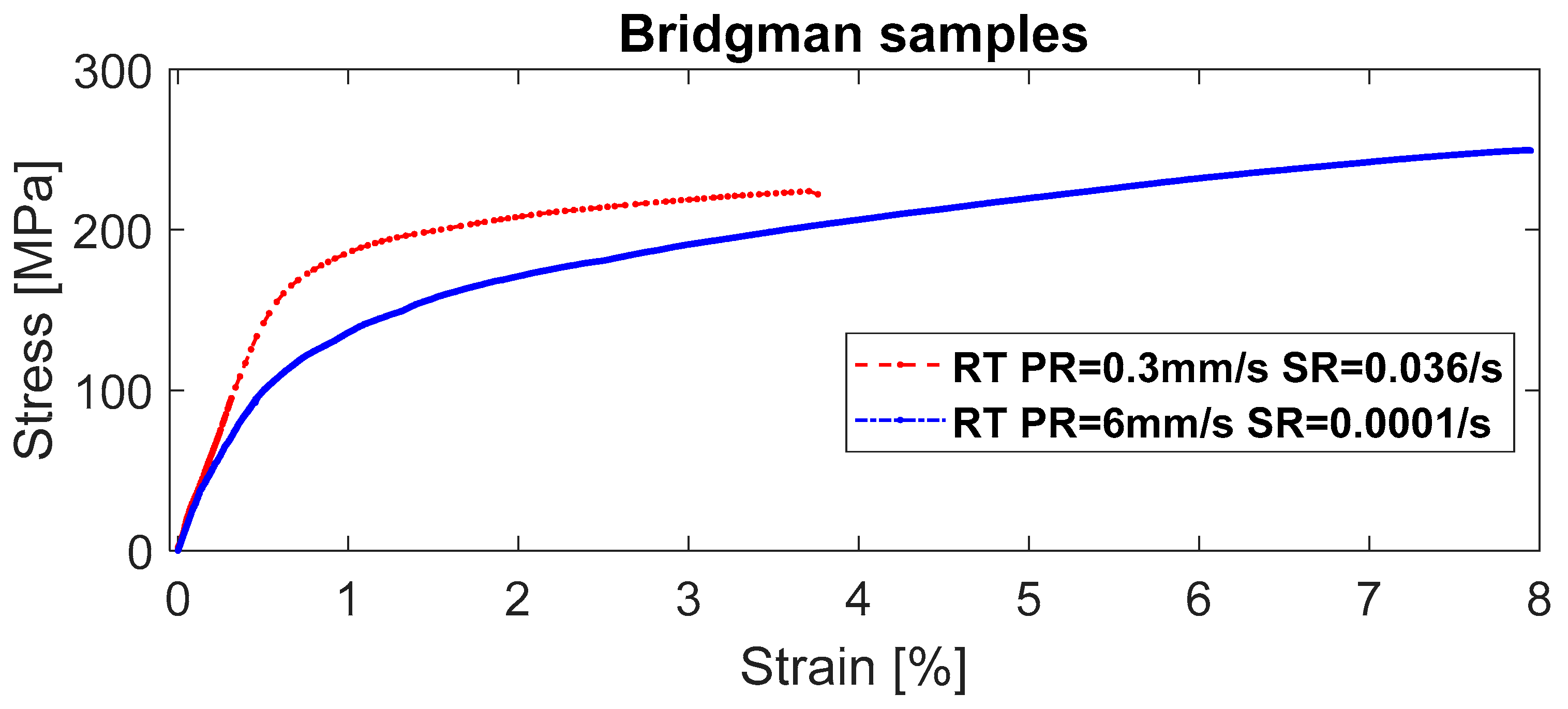
The tensile samples showed very different behaviour with the slowly solidified sample A (0.3mm/s) exhibiting higher strength compared to the rapidly solidified sample B (6mm/s). This is a contradiction to the expected result where a rapidly solidified material should have a refined microstructure and according to a Hall-Petch relationship have a higher yield point. This discrepancy warrants a closer investigation of the cause. The possible causes of this should be in the microstructure either the nucleation is very different, or the amount of secondary phases should differ strongly. The latter was previously suggested by Nagasekhar and co-authors (2,4), as well as suggested by Dini et al. (7). The relationship with grain size and strength is still under debate as illustrated by the differences in findings by Cáceres et al. (5) and by Jarfors (6). To add to the complexity the fact that lower solidification rate leads to larger grains but unexpectedly to higher amounts of Mg17Al12-particles leading to possible interconnectivity also adds to the discrepancy that warrants a deeper analysis of the microstructure of these two critical samples and their associated microstructures.
Figure 1.
Tensile test results for two Bridgeman solidified samples of AZ 91D with very different stress-strain behaviour at room temperature. (PR is the solidification rate, SR is the nominal strain rate).
Figure 1.
Tensile test results for two Bridgeman solidified samples of AZ 91D with very different stress-strain behaviour at room temperature. (PR is the solidification rate, SR is the nominal strain rate).
3.2. Microstructure
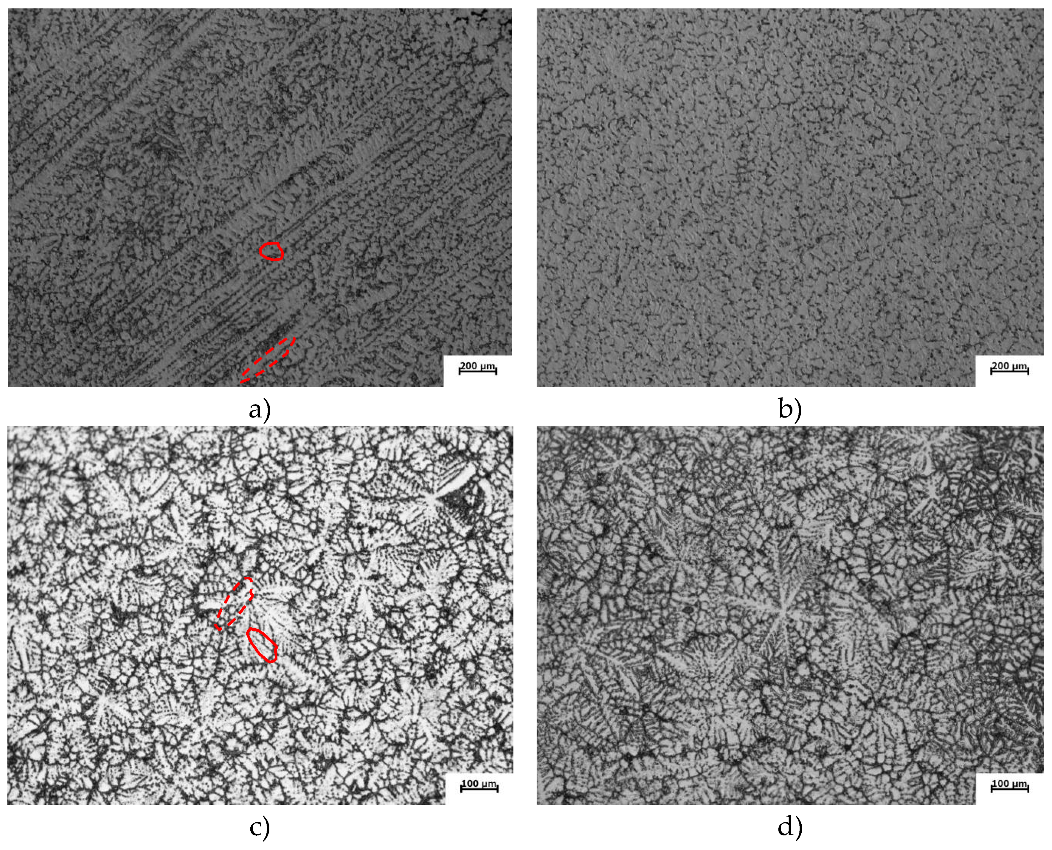
The general appearance of the microstructure was characteristic of that of a Bridgeman manufactured microstructure. The main intent was to achieve an equiaxed microstructure in the gauge region of the tensile specimen, but this was difficult for the slowest solidification rate of 0.3 mm/s as seen in the longitudinal section,
Figure 2a. In the transverse direction,
Figure 2b long secondary arms are also found in the microstructure.
At 6 mm/s the dendritic structure was broken up and an equiaxed microstructure was formed,
Figure 2c,d for the longitudinal and transverse section respectively. The equiaxed crystals showed the characteristic six arms for growth in the (0001) basal-plane.
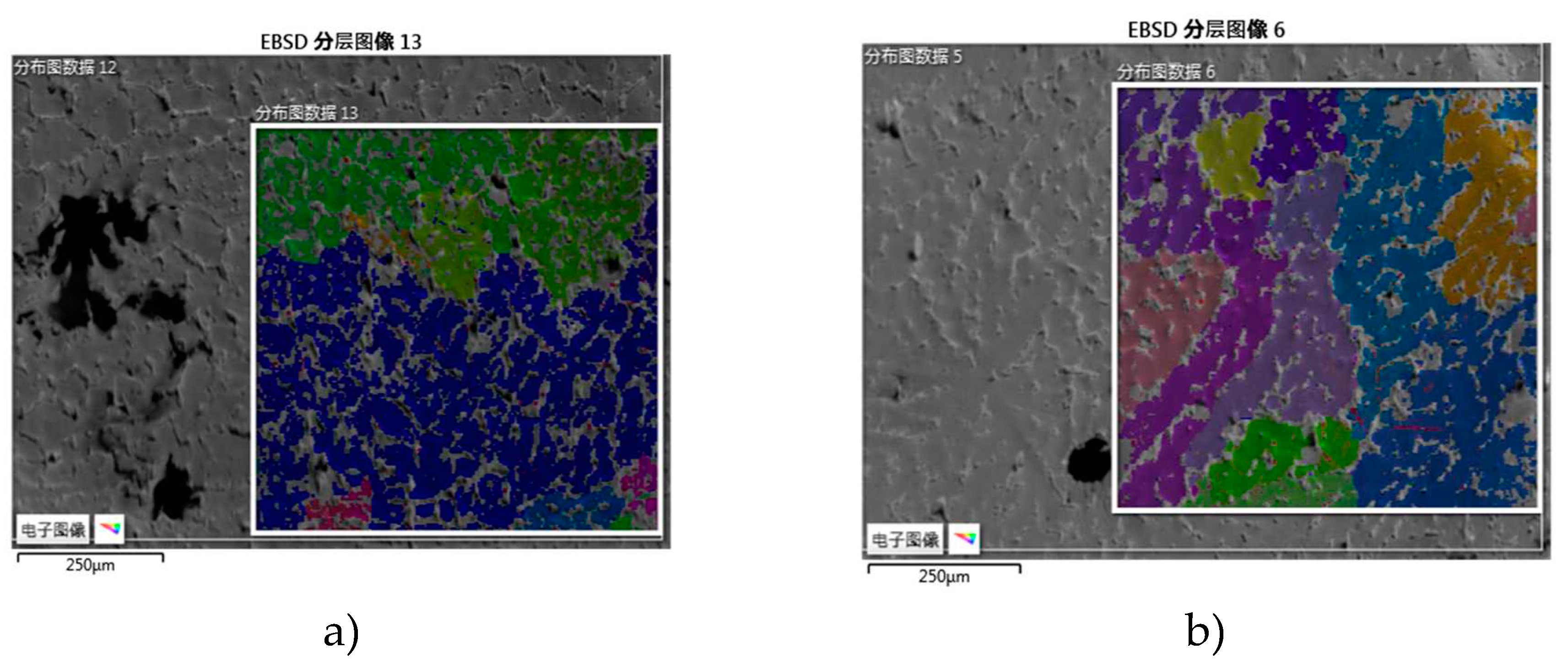
The Mg-phase was also investigated using EBSD and revealing that of the slow growth rate, large grains were present and for the high growth rate, smaller grains were present,
Figure 3a,b. This fact rules out any effects from the primary grain structure related to a Hall-Petch behaviour.
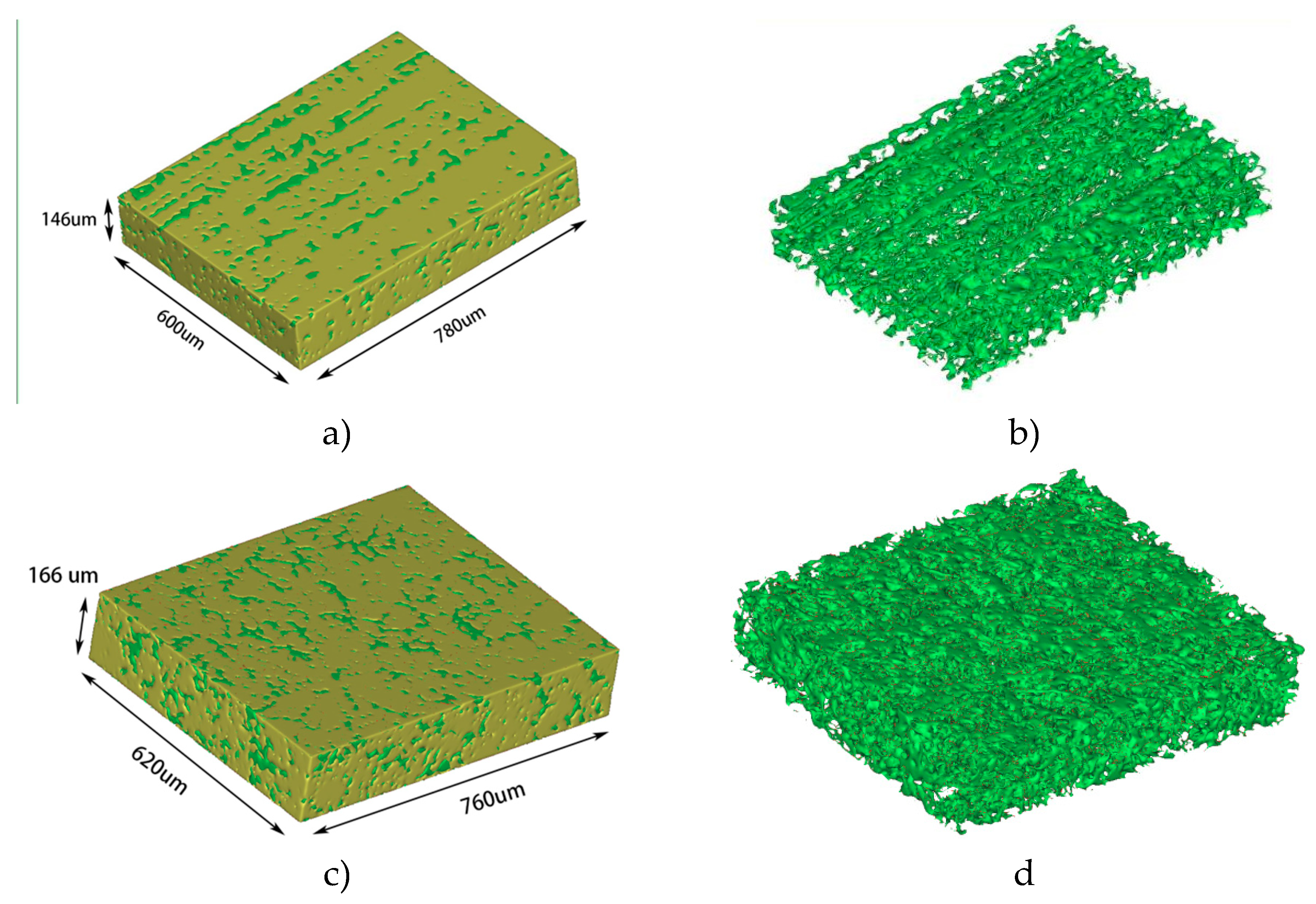
Important for the continued discussion is to establish the actual growth along the a-axis in three dimensions for the primary crystal. Doing a 3D reconstruction of the two different microstructures reveals some interesting features,
Figure 4a–d. The sample grown at the lower solidification rate, 0.3 mm/s,
Figure 4a,b, shows on the surface a well-connected and continuous α-Mg phase in the form of dendrites,
Figure 4a. In the longitudinal section, or top view, the Mg
17Al
12-phase appears continuous, but in the perpendicular direction, relative to the growth direction, this is not as evident,
Figure 4b.
The sample grown at the higher solidification rate, 6 mm/s,
Figure 4c,d, the microstructure of the Mg
17Al
12-phase visually appears larger,
Figure 4c. The primary α-Mg dendritic equiaxed grains does also provide a dense continuous structure,
Figure 4c. Separating the Mg
17Al
12-phase it shows a similar behaviour as in the sample grown at 0.3mm in the sense that it grows along the primary dendrite arms in the equiaxed grains,
Figure 4d.
In both the fast and slowly grown samples, the Mg
17Al
12-network also appears to connect in the intragranular regions as well, and as such, creating a larger and more connected network,
Figure 4b,d. The differences in appearance are striking but requires a quantitative analysis as grain size may influence the macroscopic connectivity between the Mg
17Al
12-networks between the grains. It should also be noted the scale of the eutectic also varies.
In an effort to quantify the anisotropy of the eutectic phase the divorced eutectic regions were analysed for continuity. In
Figure 2 there are eutectic regions that are connected into the inter dendritic regions and the areas where they are well confined in the dendrites in the cross section. This is partly an effect from sectioning but may also be seen as an effect related to coarsening, as dendrite arms are joining during the coarsening process. The number of intercepts for the different regions were measured. A total length 8257 µm was measured in each cross-section as shown in
Table 1. The entities used for characterizing the microstructure are found in the appendix. The amount of eutectic appeared not to vary significantly between the different growths rates with approximately 20% eutectic measured for both growth rates, excluding variations in the fraction eutectic as the main reason for the difference in mechanical behaviour, leaving only structural arrangement or structural scale as the possible remaining explanations.
The first matter to note is that the actual continuity of the eutectic regions,
fc, were greater at a higher growth rate and showed an isotropic relationship between the transverse and perpendicular sections relative the growth direction. Intermetallics are typically harder than metals and this is also the case for Mg
17Al
11. The higher degree of connectedness with the higher growth rate contradicts the fact that the slower growth rate results in a higher strength and is as such not the explanation. It should be noted that what is seen in
Figure 4b, that there appears to be an anisotropy in the connectedness between the longitudinal and the transverse direction is confirmed with the calculated difference in connectedness,
Table 1. However this is not the origin of the difference in strength but may explain the effects found for the thermal expansion reported by Dini et al. (7)
The typical overall microstructural scale, DAll, does show the expected value from a growth rate point of view with a finer overall dimension with a higher growth rate. Again, this relationship does not match the expected mechanical behaviour and is as such cannot the reason for this inverse mechanical behaviour. Turning to the specific scales for the open microstructure DO and the confined microstructure DC shows a different correlation. The confined scale DC is smaller for the higher growth rate making it necessary to exclude the confined areas as well from the explanation of the increased strength at lower growth rate.
The open structure scale, DO, on the other hand shows a significant difference between the slow and fast growth rates. The slow growth rate produce a much finer microstructure than the microstructure at the higher growth rate. Since this measure is a measure of the number if interfaces between the dendrites and the open eutectic regions it is a combined scale of primarily the SDAS and the divorced eutectic Mg17Al11 particles. A possible interpretation of this is that as the primary grain structure is reduced the ability for the Mg17Al11-phase to form connected structures in the regions between the growing grains increase. Similarly, as the primary grains increase the connectedness will primarily be interdendritic making it less connected and of a finer scale.
3.3. Fractography
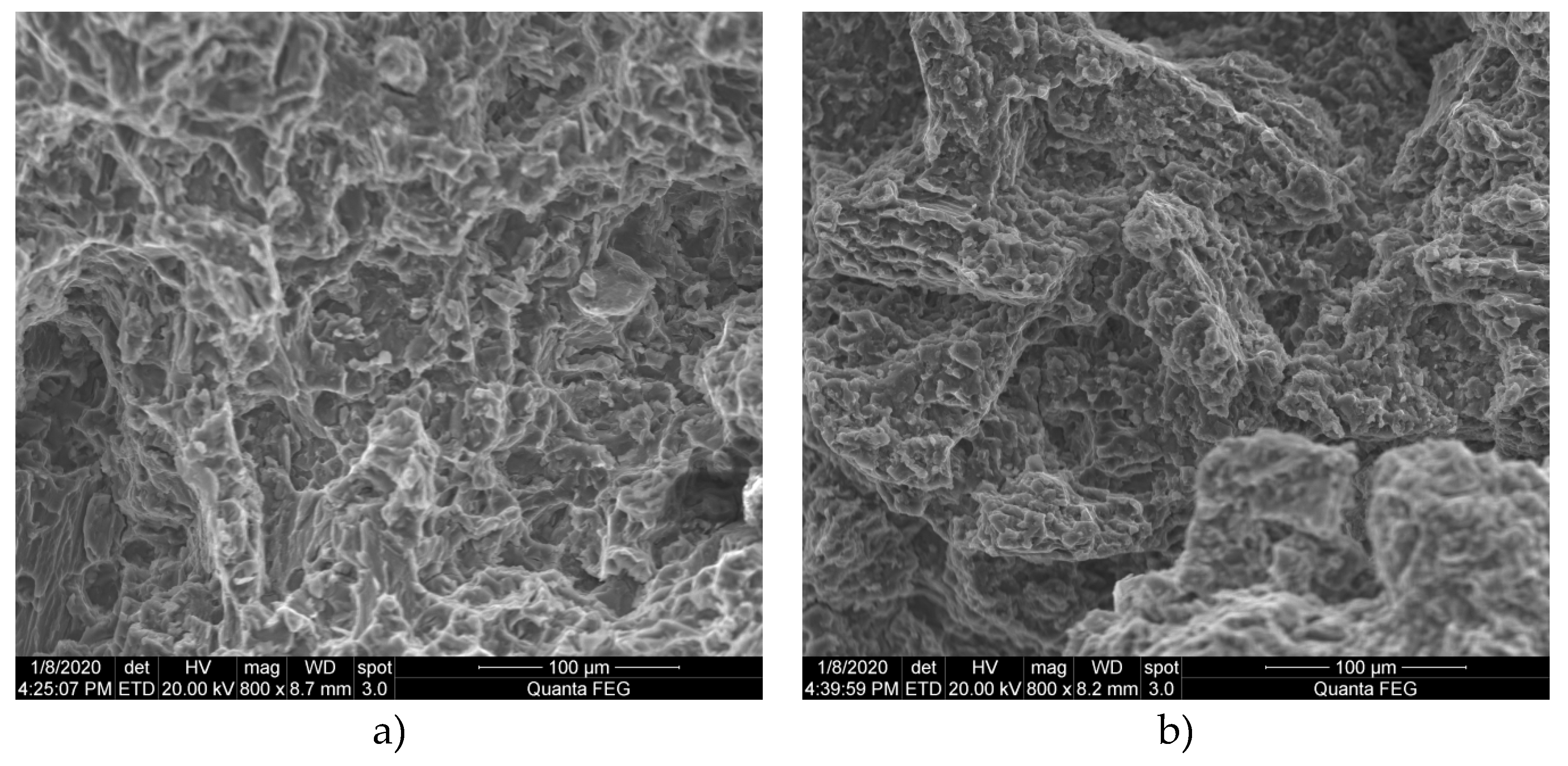
The fracture surfaces for both solidification rates displayed a mixed-mode failure with ductile ridges with brittle regions. The fracture for the slowly solidified material appeared somewhat more ductile with ductile ridges spread across the fracture surface,
Figure 5a compared to the faster-solidified material,
Figure 5b. The fast-solidified material had regions with angular features and macroscopic steps in the microstructure. This indicated an overall more brittle behaviour on the microscopic scale. The fact that the fracture appears more brittle in the fast solidified sample is also supported by the higher degree of connectedness in the eutectic regions which are more brittle and the preferred crack propagation paths. The intragranular crack path on the other hand becomes more tortuous and supports a higher ductility.
4. Conclusions
In the current study, the nature of the Mg17Al12-phase and its influence on strength and ductility was investigated. The background was the previous findings on the formation of a three-dimensional network Mg17Al12 in High-Pressure Die-Cast (HPDC) AZ91D. (3, 4). The nature of the Mg17Al12-network has been regarded as one reason for the difficulties to achieve a meaningful Hall-Petch relationship by Cáceres et al. (5), while Jarfors (6) found a meaningful description.
The first important observation in the current study was that the connectedness in the slowly grown materials was lower and that the scale of the divorced eutectic became finer with the larger grain size. These two facts resulted in a higher yield point.
For both materials , fractography revealed that the interface Mg17Al12/α-Mg was the weak point in the microstructure, leading to the second observation. The connectedness in the fast grown sample was higher than in the slowly grown material. The faster grown materials had smaller primary grain size leading to that Mg17Al11 particles formed a network in the regions between the primary particles. This increases the scale of the divorced eutectic with a lower strength as a result.
A third observation was that the intragranular crack path results in a more tortuous crack path allowing for an improved ductility despite that the fracture appeared more brittle.
Author Contributions
Jarfors made conceptualization; methodology devised by Jarfors and Yang; investigation, made by Andersson, Yu and Xia; resources organized by Jarfors and Yang; writing—original draft preparation, Jarfors; writing—review and editing, All authors together; funding acquisition, Jarfors and Yang. All authors have read and agreed to the published version of the manuscript.
Funding
This research was partly funded by the Knowledge Foundation, grant number 20170077.
Acknowledgements
The authors acknowledge Husqvarna AB for supplying the alloy used in the current study.
Conflicts of Interest
The authors declare no conflict of interest. The funders nor material suppliers had any role in the design of the study; in the collection, analyses, or interpretation of data; in the writing of the manuscript, or in the decision to publish the results.
Appendix A. Definition of metallographic parameters
The entities that were measured were the number of intercepts between the primary precipitated phase and the eutectic regions. These intercepts were defined as intercepts to confined regions,
NC, and intercepts to open regions,
NO. Confined means that the eutectic region is confined within the cross section to an isolated interdendritic region not communication to other regions. The fractions confined,
fC, and fraction open
fO were defined as
and
The total length measured in a sample
LTot was used to define the scales in the microstructure with
DAll representing a typical scale,
DC and
DO representing the scales of the confined and open areas. It should be noted that with these definitions the grain size and the secondary dendrite arm spacings are implicitly included in the measures, dominating the open measure primarily as the dendrites are bounded by the eutectic and included in the length measures. The characteristic measures were then defined as
and
and
The eutectic and primary fractions were calculated according to the line lengths method where a number of lines were randomly drawn in the microstructure. The lengths,
Leut being the length of a line in the eutectics and
Lprim the length of the line in the primary areas as
and
References
- Prakash DGL, Regener D. Quantitative characterization of Mg17Al12 phase and grain size in HPDC AZ91 magnesium alloy. J Alloys Compd. 2008;461(1–2):139–46.
- Nagasekhar A V., Caceres CH, Kong C. On the development of a pseudo micro-truss intermetallic microstructure in a high pressure die cast AZ91 alloy. J Phys Conf Ser. 2010;240.
- Amberger D, Eisenlohr P, Göken M. Microstructural evolution during creep of Ca-containing AZ91. Mater Sci Eng A. 2009;510–511(C):398–402.
- Nagasekhar A V., Cáceres CH, Kong C. 3D characterization of intermetallics in a high pressure die cast Mg alloy using focused ion beam tomography. Mater Charact [Internet]. 2010;61(11):1035–42. [CrossRef]
- Cáceres CH, Griffiths JR, Pakdel AR, Davidson CJ. Microhardness mapping and the hardness-yield strength relationship in high-pressure diecast magnesium alloy AZ91. Mater Sci Eng A. 2005;402(1–2):258–68.
- Jarfors AEW. Grain size and secondary dendrite arm spacing; A priori discussion on the difference between FCC and HCP materials. In: Magnesium Technology 2018. 2018. p. 51–5.
- Dini H, Andersson N-E, Jarfors AEW. Effects of Microstructure on Deformation Behaviour of AZ91D Cast Alloy. TMS2014 Annu Meet Suppl Proc. 2014;565–72.
|
Disclaimer/Publisher’s Note: The statements, opinions and data contained in all publications are solely those of the individual author(s) and contributor(s) and not of MDPI and/or the editor(s). MDPI and/or the editor(s) disclaim responsibility for any injury to people or property resulting from any ideas, methods, instructions or products referred to in the content. |
© 2023 by the authors. Licensee MDPI, Basel, Switzerland. This article is an open access article distributed under the terms and conditions of the Creative Commons Attribution (CC BY) license (http://creativecommons.org/licenses/by/4.0/).
