
Submitted:
29 October 2022
Posted:
07 November 2022
You are already at the latest version
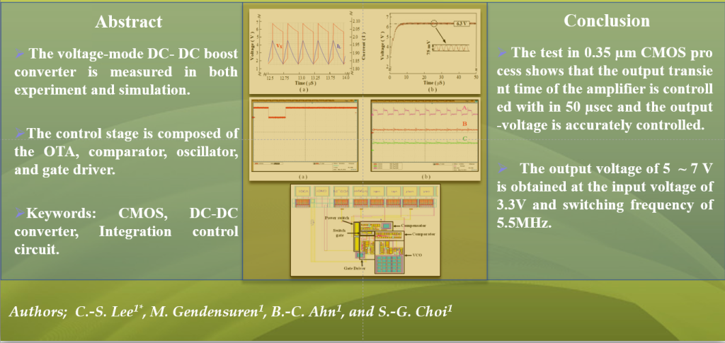
Abstract
The integrated DC-DC converter is appropriate for use in many domains, namely, display, cellular, and portable applications. This paper presents an integrated monolithic voltage-mode DC-DC boost converter with a low-power control circuit. The driver circuit requires an integrated converter to power up a digital logic circuit and converts the unregulated DC input to the controlled DC output at the desired voltage level. It is the integration of both power switches and control circuitry within the same CMOS technology to buck down and boost voltages using a switch mode regulator. In order to increase power efficiency in the DC-DC boost converter that provides low-power operation with a small chip size, a low-voltage operation is applied to the unique circuit characteristic. The operational transconductance amplifier(OTA), comparator, and oscillator in the control circuit are designed with the supply voltage of 3.3V and the operating frequency of 5.5 MHz. A compensator is used to create a pole that has sufficient phase margin for high stability. The DC- DC boost converter is measured in both experiment and simulation. Testing of the proposed circuit on the 0.35μm CMOS process shows that the output transient time of the amplifier can be controlled within of 7μsec and the output voltage is accurately controlled with a ripple ratio of 3%.
Keywords:
CMOS
; DC-DC converter
; control circuit
; integration
; voltage –mode
; boost converter
Copyright: This open access article is published under a Creative Commons CC BY 4.0 license, which permit the free download, distribution, and reuse, provided that the author and preprint are cited in any reuse.


