Preprint
Article

Crater Formation under Extreme Space Weather Conditions

Altmetrics

Downloads

170

Views

170

Comments

0

This version is not peer-reviewed

Submitted:

31 December 2022

Posted:

04 January 2023

You are already at the latest version

Alerts
Abstract
We consider an alternative hypothesis of crater formation -- through an electric discharge machining (EDM) of the celestial bodies' surfaces. The source of the energy and the current itself may lie in the plasma infalling on a celestial body (from an extremely strong solar outburst or a nearby supernova). This mechanism may have been even more important than impact cratering in the early Solar System, with potential implications to the history of the dynamics of the System itself and solar activity in particular. In this light, the conclusion that shocked and metamorphosed minerals found within crater sites are evidence of hypervelocity impacts might be reconsidered. There are ambiguities that remain among sources of mineralogical formations. This study is ongoing with details of investigations supporting a new approach to crater formation not yet exhausted. Apart from mineralogical analysis and theoretical considerations regarding the large scale crater formation, we present a description of experimental studies of EDM acting at low pressures. Experimental results are made with crude setups and could easily be replicated on a larger scale with valuable research potential, as there is a well understood relation between the crater size and the energy needed for its production.
Keywords: 
Subject: Physical Sciences  -   Astronomy and Astrophysics

Highlights

  • Craters might be produced by electric currents both in laboratory conditions and on celestial bodies
  • An extremely large solar outburst or a nearby supernova may cause cratering of Solar System bodies
  • Laboratory electric discharge machining is a useful tool for studying larger scale craters
  • Piezoelectricity may play a major role even in impact cratering
  • Electrically induced cratering may solve some problems of impact crater hypothesis

1. Introduction

In the assorted fields of space sciences, particularly astrogeology, the study of craters occupies a modest region. Despite this, crater distribution on solid bodies implies the age of a body can be inferred by studying its cratered surface [1]. Craters are found, for the most part, on every solid surface in the Solar System. For this investigation we will focus on bodies sustaining thin to no atmospheres (the Moon, Mars) because of low pressures at the surface and lack of crater eroding weather. Limitations in data availability dictate citation of terrestrial crater research regarding most mineralogical analyses.
There exists a range of crater shapes and sizes. Although most craters typically have a circular shape, details and anomalies can be found that require peculiar explanations. I.e. most craters are circular but in some cases are oblate, some have straight edges like a hexagon, some pairs of craters share a floor while another pair has distinct rims that separate the floors etc. Small craters are typically bowl shaped depressions with diameters under 10 km. As craters increase in size, varying features of complexity are found, giving rise to the term “complex crater”. The features of a complex crater include broad flat floors, terraced ridges, central peaks/central pits. Studies to understand these varying features are conducted within the impact hypothesis [2]. The impact hypothesis gained attention when experimental evidence has shown that a collision with an object traveling faster than 3 km/s has explosive results [3,4]. This would suggest larger bodies traveling at greater velocities would have extremely explosive results, as experiments had shown that even small objects can produce large impacts at high velocities. The formation of impact craters is broken down into 4 different stages [2]. These stages continuously progress into one another, but when separated they are: contact, compression, excavation, modification.

1.1. Impact Crater Formation

1.1.1. Contact

During the first stage, the infalling body comes into direct contact with the target body. Typically, the impacting body is stopped in a fraction of a second and only penetrates the target’s surface to the depth of 1–2 of its own diameter [5], which, according to the models, leads to the production of shockwaves that propagate into the target from the interface surface, as well as backwards into the body of the impactor. When the wave reaches the rear of the impactor, it is being reflected back as a rarefaction wave, releasing tension in the impactor’s body and leading to its immediate melting or vaporisation.

1.1.2. Compression

During the second stage, the compression of the impacted surface under the influence of the generated shockwaves takes place. At this time the shockwaves rapidly lose energy (due to the increase in the wavefront area, as well as energy losses for heating, deformation and acceleration of the target’s rock)—models expect this loss to be exponentially dependent on distance from the contact point. For the typical cosmic impact velocities peak pressures of above 100 GPa are expected, which decrease with distance and eventually reach 1–2 GPa, at which point they turn into regular elastic (seismic) waves and their velocity drops to subsonic (less than 5–8 km/s). They may produce additional effects such as fracturing, brecciation, faulting, and landslides. When the rarefaction wave reflected back from the rear of the impactor reaches the target’s compressed surface, the compression stage is considered to be over.

1.1.3. Excavation

During the third stage the shockwaves produced by the impact reflect from the surface of the target (as their source lies below its surface) as rarefaction waves. In case if the release produced by these reflected waves exceeds the rock’s strength, it fractures and shatters, as well as receives outwards acceleration in the form of small fragments traveling at high velocities. This process leads to the formation of a bowl-shaped depression—a transient crater. This crater’s size is at least an order of magnitude larger than the size of the impactor, it has a paraboloid shape and its depth is about 1/3 of its diameter. When the transient crater has grown to its maximum size, the excavation stage ends.

1.1.4. Modification

The final stage is characterized by various modifications of the transient crater, most notably the ones caused by gravity (such as the inward wall collapse) and rock mechanics (fracturing etc.). This stage has no marked end, as after the initial formation of the crater it is still being affected by the usual processes of geological mass movement, isostatic uplift, erosion, and sedimentation, all of which affect its final shape.

1.2. EDM as an Alternative

What is usually understood by the term EDM is a process used by the manufacturing industry for a range of plasma machining applications with precise results. In the context of this paper, by “EDM hypothesis” we would refer to a proposal that large scale electric discharges may occur naturally and result in electrically machined surfaces of large bodies.
In [6] the author states that “the concept of an inconceivably large lightning storm taking place between Earth and Moon is certainly a strange new idea, but it does account for many of the features seen on the lunar surface”. Brian J. Ford was the first to document the electrical hypothesis of lunar crater origins. The cited paper describes the results of EDM experiments that suggested a possible electrical origin of craters. He tabled ratios of central peak incidence to those in EDM experiments to which there was a correlation. Ford also notes the formation of craters on the rim of an existing crater on the lunar surface—a feature in EDM that is produced as a result of changing potentials between discharging bodies.
Physicists C.J. Ransom and W. Thornhill conducted experiments [7] that have produced round, flat floored craters, and an assortment of spherules and welded spherules. The team produced analogues to the “martian blueberries” [?] and concluded that the results would indicate Mars underwent a catastrophic electric discharge in the past. Spherules are indeed found and have been studied in terrestrial craters: e.g. Colônia Crater, Brazil, studied by Victor F. Velázquez [8] hosts a range of spherules resembling those produced in laboratory conditions by C. J. Ransom and W. Thornhill.
Independent researcher Robert Hawthorne studied Upheaval Dome (Canyonlands National Park, UT, USA). His research suggests that glasses, spherules, and shocked materials found there could indeed have been produced by EDM [9]. Samples of material studied with electron microscopy were analcime. Dr. W. Cassidy of the University of Pittsburgh reported to R. Hawthorne that ”Preliminary observations are that it consists primarily of irregular shaped, colorless grains of isotropic material, accompanied by rare rounded isotropic grains. Both the irregular and rounded isotropic grains are probably glass”.
A feature that may be associated with crater formation is the sinuous rille. These structures are found on the lunar surface and appear as long meandering valleys. Theories to explain these include ancient rivers and lava tubes, however research has shown these theories are problematic in light of close analysis of rille structures [10]. An alternate hypothesis proposed by R. Juergens suggests lunar rilles are the result of a thermal dielectric breakdown of the crust [11]. This might further be supported by samples returned by the Apollo 15 mission taken from a rille site. Samples returned [12] contained largely homogenous green glass spheres with cooling rates greater than what can be associated with volcanism (1000 F/s). The cooling rates could be associated with impacts, however, impact glasses tend to be non-uniform—the result of an explosive process that mixes surface and subsurface materials. Another evidence of rilles being a relic of a previous electromagnetic phenomena would be their magnetization: they appear visually brighter because of the lower weathering by solar wind due to being shielded by intrinsic magnetization [13], an order of magnitude higher with respect to the “ambient” lunar rock [14]. This magnetization may be the remnant of the currents passing through the rille minerals in the past.
B. Ford’s original hypothesis suspects incredibly high temperatures that would result from the Earth and Moon being closer together at one time after their formation. “The high temperatures prevalent at this time would strongly suggest the presence of a highly ionized ’plasma’ associating the Earth and Moon”. There is evidence to support B. Ford’s idea (at least the EDM component). Although this would upend current understanding of asteroid, comet, crater and meteorite formation, B. Ford’s “close proximity” concept might be reinforced by mineral morphology. This would be considered under auspices of cristobalite, pyroxene, carbonates, and silicon carbide found in craters, comets, asteroids, meteors and fulgurites [15,16]. This suggests that what is considered impact shocked and metamorphosed minerals, nonetheless may be the result of ejected material via electric discharges or combination of effects (see Section 5.1 for a more detailed discussion).

2. Material and Methods

There are four components involved to obtain the results: (1) vacuum; (2) EDM source; (3) chamber; (4) soil content. The level of vacuum desired is a pressure low enough that the vapor pressure of water is equal to the atmospheric pressure. EDM cratering works in atmospheric pressures, but the effects are less, and short lived. It was typical that each experiment was conducted with a ∼3% atmosphere (23 Torr). A vacuum pump CPS VP6D was employed to achieve low pressures. The EDM source was a neon sign transformer Allanson 101530BPX120R rated for 15 kV at 30 mA, controlled by a variable transformer (variac). The HV transformer leads were connected to a rectifying circuit to obtain DC voltage. The chamber was a 1.5 liter chamber. At the bottom of the chamber was an electrode, while a brass valve at the top of the chamber served as the opposing electrode (20 cm distant), the brass valve connected the chamber to vacuum. The soil samples were random clumps of dirt gathered from outdoors. Dirt was dropped in through the valve in crude fashion, leaving only shaking the chamber as a means of controlling soil distribution at the bottom. Electrode placement was initially 2–3 cm beneath the soil surface. It was best to obtain a healthy mixture of fine and coarse grains. If the sample contained all fine grain, the surface boils and obscures observation. If all coarse, there is little detail to be studied. The results were documented on a Sony HDR-CX405 camera.
Power was applied by slowly increasing the dial of the variac. Discharges at the surface would occur at 10–30 V o u ( V o u —variac output, 110 V o u = 15 kV output from the HV transformer leads). V o u was generally increased and maintained around 80 (10.9 kV). There is a correlation between increasing V o u and visible increase in crater formation.
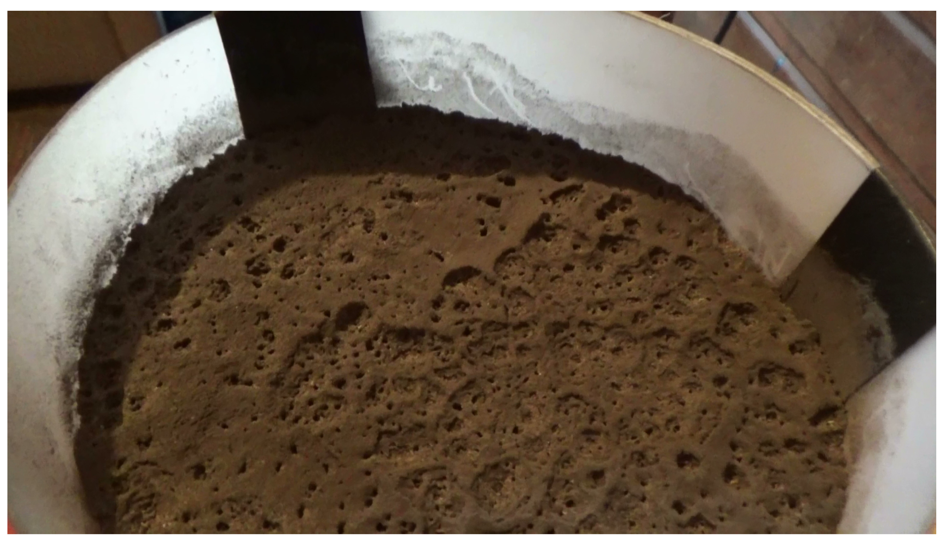
In this setup discharges will occur at 130–150 Torr with 110 V o u (15 kV). Craters formed in higher pressures are noticeably smaller. The vacuum source was controlled by opening and closing the valve at the top of the chamber. When the chamber reaches 22.8 Torr, boiling occurs producing a porous surface with pinhole sized channels. These channels themselves can also grow in size forming craters with terracing around the pinholes (Figure 1. Uplifting fine grains during this volatile point would sometimes go beyond view of the camera [15 cm] from the surface. The effects of low pressure on different soil samples is indeed varying. It was typical to wait until boiling subsided before applying the voltage.
The first experiments were done in a closed system, meaning, after ∼23 Torr was achieved, the chamber was disconnected from the vacuum and subjected to high voltage. In this scenario, when a crater forms at the surface, gases are introduced into the atmosphere increasing pressure inside the chamber—this is observed via increasing current density of the plasma. In all following experiments the chamber was connected to a running vacuum that was controlled by on and off, thus the physical limitations of the pump controlled the level of vacuum. The atmosphere was sustained at 23 Torr while the vacuum pump was active.
To be sure, having the cathode in the soil produced all of the observations. Placing the anode in the soil did not produce significant EDM effects. (At least with this power source). The depth of the cathode has an effect on crater formation, the most notable is duration. Because of resistance in electric current flow, soil being removed decreases resistance in the circuit. As a more conductive path is formed, less EDM excavation will take place. Resistance in the path is also decreased by the formation of fulgurites on the cathode.

3. Theory

3.1. Basic Model

Regarding the cosmic scale electric currents, which may cause cratering on celestial bodies according to the EDM approach described in Section 1.2, we shall use a simple model taken from [17]—see Figure 2. Here an infalling beam of magnetized low density plasma encounters a conducting surface, and, moving approximately along the equipotential surfaces, is deviated in the direction parallel to the surface. The result is the appearance of electric currents, effectively transforming a part of the kinetic energy (unfortunately, it is impossible to determine how big that part is from first principles, so we shall limit ourselves with a boundary type order-of-magnitude estimations from hereafter) of the beam into the electromagnetic energy of the circuit. Any increase in beam intensity would enhance the magnetic field at the bends, and the deceleration and energy transfer would only increase, so the currents would become stronger. At large intensities an inertia surface current (a “shock”) may also be produced.
Along the lines of the EDM approach we may claim that it is the areas A and A’ (Figure 2 where the surface part of the current closes with the plasma part that are the prime candidates to search for the EDM produced craters, as the currents enter and exit the surface in these places. In this case the conducting surface would correspond to the surface of a celestial body, while the infalling plasma might come, for example, from the Sun (in the form of a dense coronal mass ejection—CME—cloud) or perhaps from outside of the System in the first place (e.g. an interstellar plasma cloud from a nearby supernova explosion).
Let’s evaluate the current strength that might be produced through this mechanism. This would allow us to get an expression for the energy dissipated by the current in the conducting plate (i.e. the surface of a celestial body that undergoes cratering). The deviation of plasma is caused by the magnetic field of the arising current itself, so the particles of plasma (we shall assume these are protons) are moving in circular arcs under the influence of the Lorentz force:
q v B = m v 2 R ,
or q B = m v R , where B is the magnetic field produced by the current (not the magnetic field of plasma itself as in Figure 2—they are, in our case, pointing in the opposite directions), q is the charge of one particle, m is its mass, v is its velocity (equal to the velocity of the plasma beam), R is the radius of the circle along which the plasma particles are moving (we shall consider it being equal to some typical linear size of the problem and use it as such in further expressions). Then
B = m v e R ,
where q = e is the elementary charge. To estimate the current strength, we need to solve the equation
× B = μ 0 ( j + ϵ 0 E t
(here μ 0 is the vacuum permeability, ϵ 0 is the vacuum permittivity), but for an order of magnitude estimation we shall just assume that the current loop is circular and use a simple expression for the magnetic field at its center:
B = μ 0 I 2 R .
So the current
I = 2 B R μ 0 = 2 m v e μ 0 .
And now let’s estimate the dissipated heat using Joule’s law:
Q = I 2 r t = 4 m 2 v 2 t e 2 μ 0 2 · l σ A = 4 m 2 v 2 t l e 2 μ 0 2 σ A ,
where r is the resistance of the part of the circuit where the energy is dissipated (the conducting plate with a current), t is some characteristic time during which cratering is taking place, σ is the conductivity of the plate’s material, l is the linear length of the current, A is the area of the current cross-section. It is apparent from this expression that optimal conditions for cratering require the reduction in A, i.e. the current density should be as high as possible. In practice this means that the current should be strong enough to be able to pinch into a narrower channel, with the attraction of neighboring parts of the current overcoming thermokinetic repulsion of plasma particles [18]. Otherwise, if it’s too diffuse and spread out over a large area in the conducting plate, no cratering would take place. Hence we should only expect cratering from fast and dense plasma beams that are able to produce the current strong enough to undergo pinching and elevate the Q value. Some numerical estimates of that and additional considerations are given in Section 5.

3.2. Experimental Case

Given the considerations outlined in Section 3.1, the experiment that we present attempts to practically model the part of the circuit where the current is perpendicular to the surface and links the “plasma” branch with the “surface” branch, i.e. in the areas A and A’ in Figure 2. These areas are most obvious places for the craters to appear in the framework of EDM hypothesis and the simplistic plasma model discussed above.
Practically, it seems that laboratory craters made in such a way are produced due to the electrostatic charging of the particles of the soil, which are then being removed from the surface (and later, perhaps, become electrically neutral somewhere mid-flight on the way between electrodes due to collisions with charges of opposite signs). In this sense even though the craters in the experiment are produced electrically, the exact physical mechanism for the formation of scaled up craters on celestial bodies may differ, as the scaling of the energies involved would make it closer to a very brief high voltage discharge (associated with the production of shockwaves in the affected surface minerals etc.) rather than a relatively slow and consecutive material removal, as observed here.
The experimental observation that only placing the cathode in the soil produces cratering (see Section 2 deserves some attention. The most obvious explanation would be that the charging of the soil particles by the electrons is enhanced due to higher mobility of the latter with respect to heavier positive ions. Perhaps another factor would be the bombardment of the soil surface by these heavier air ions at the same time, which would mechanically enhance the soil volatility and make the removal easier. Whether the same situation would be observed at larger scales is a difficult question. It appears that this is not necessarily the case.

4. Results

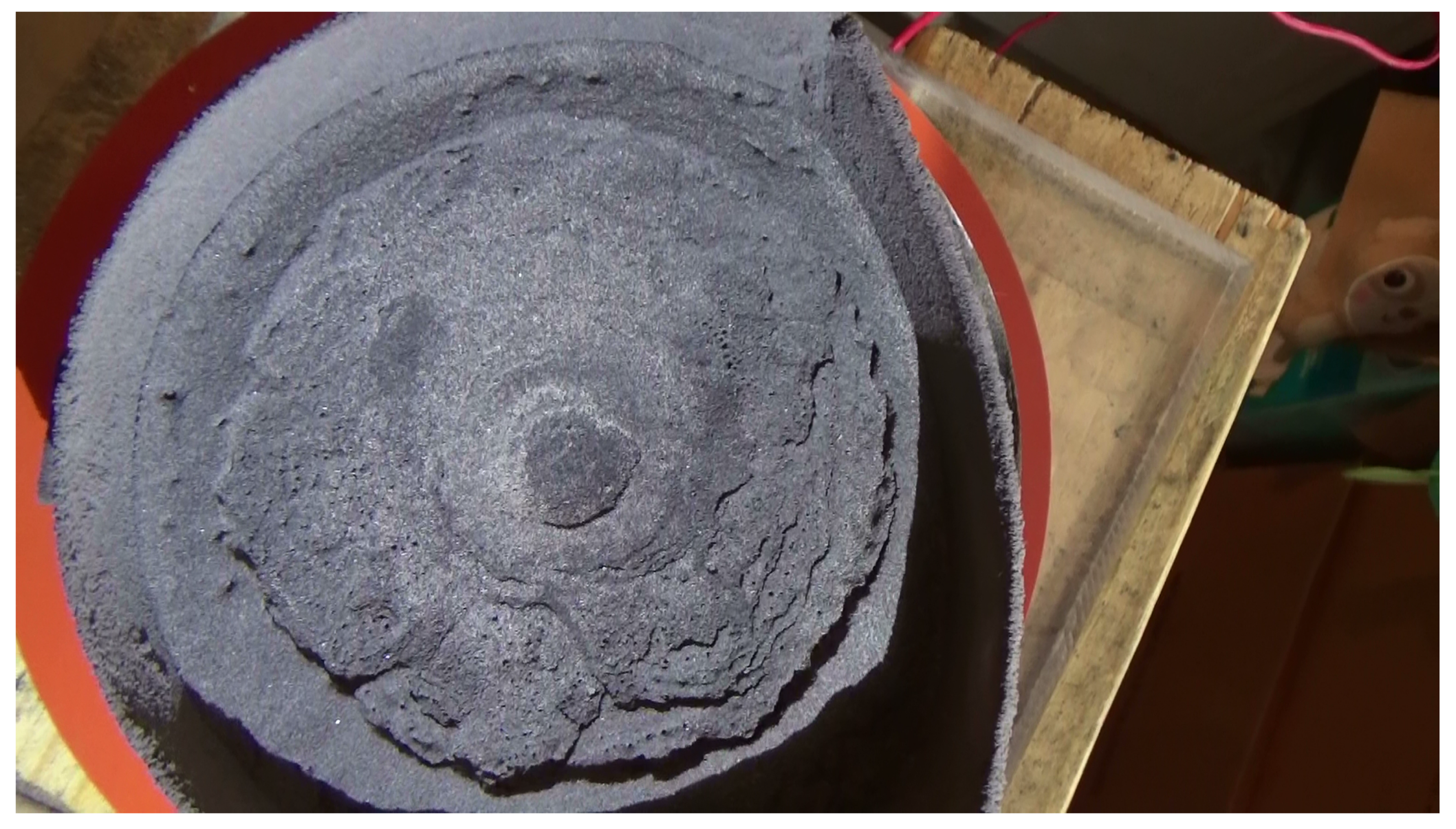
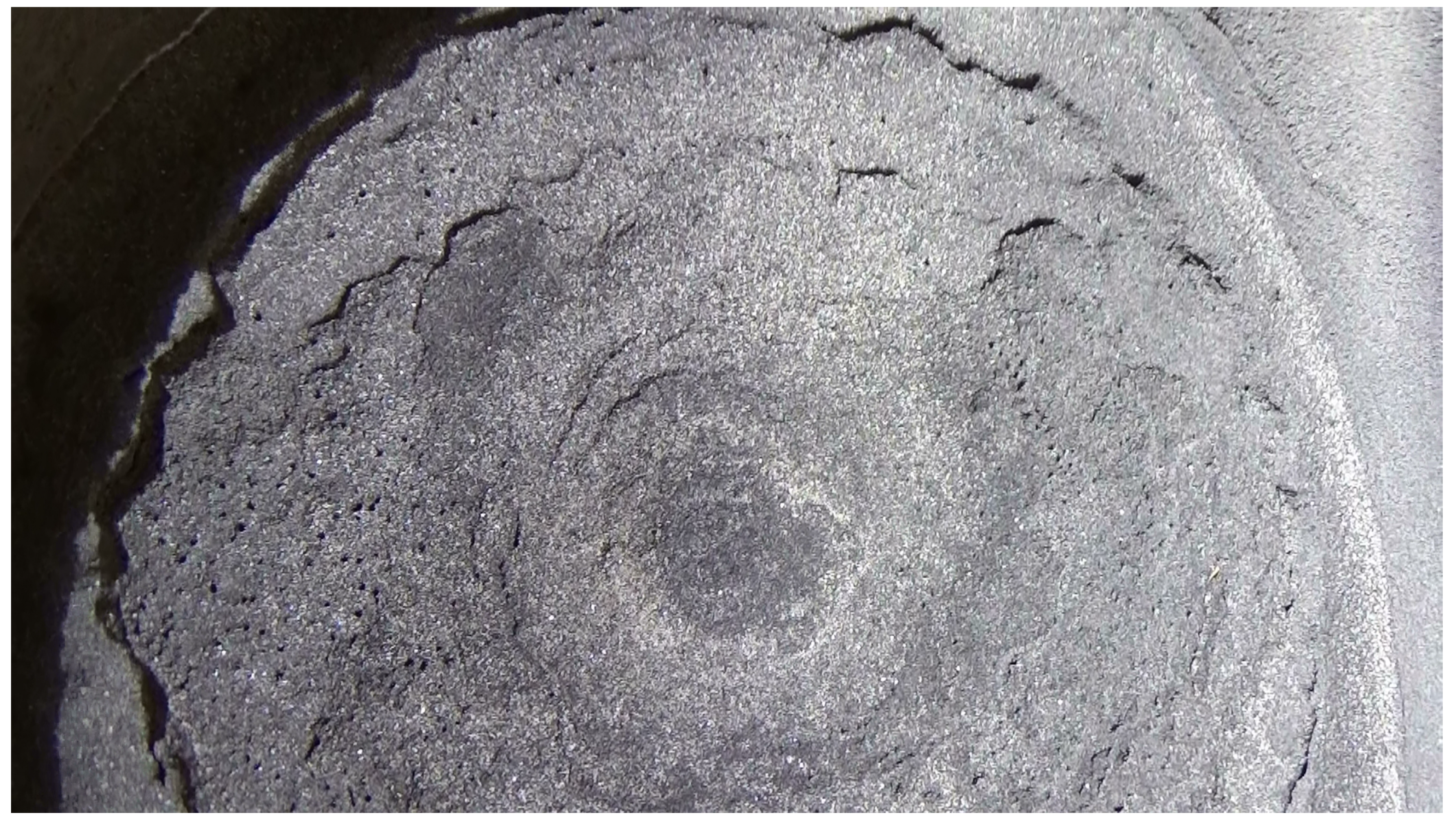
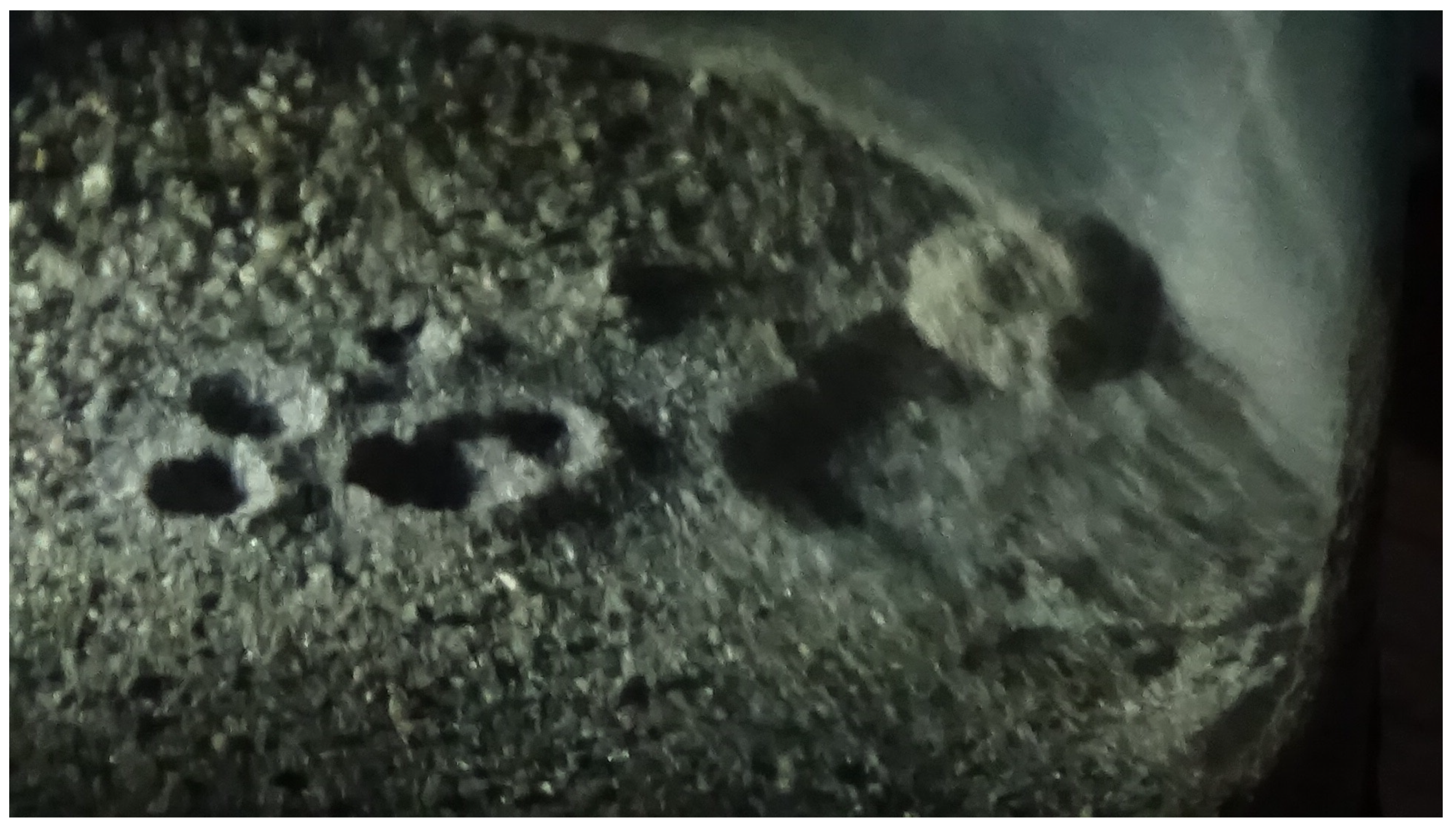
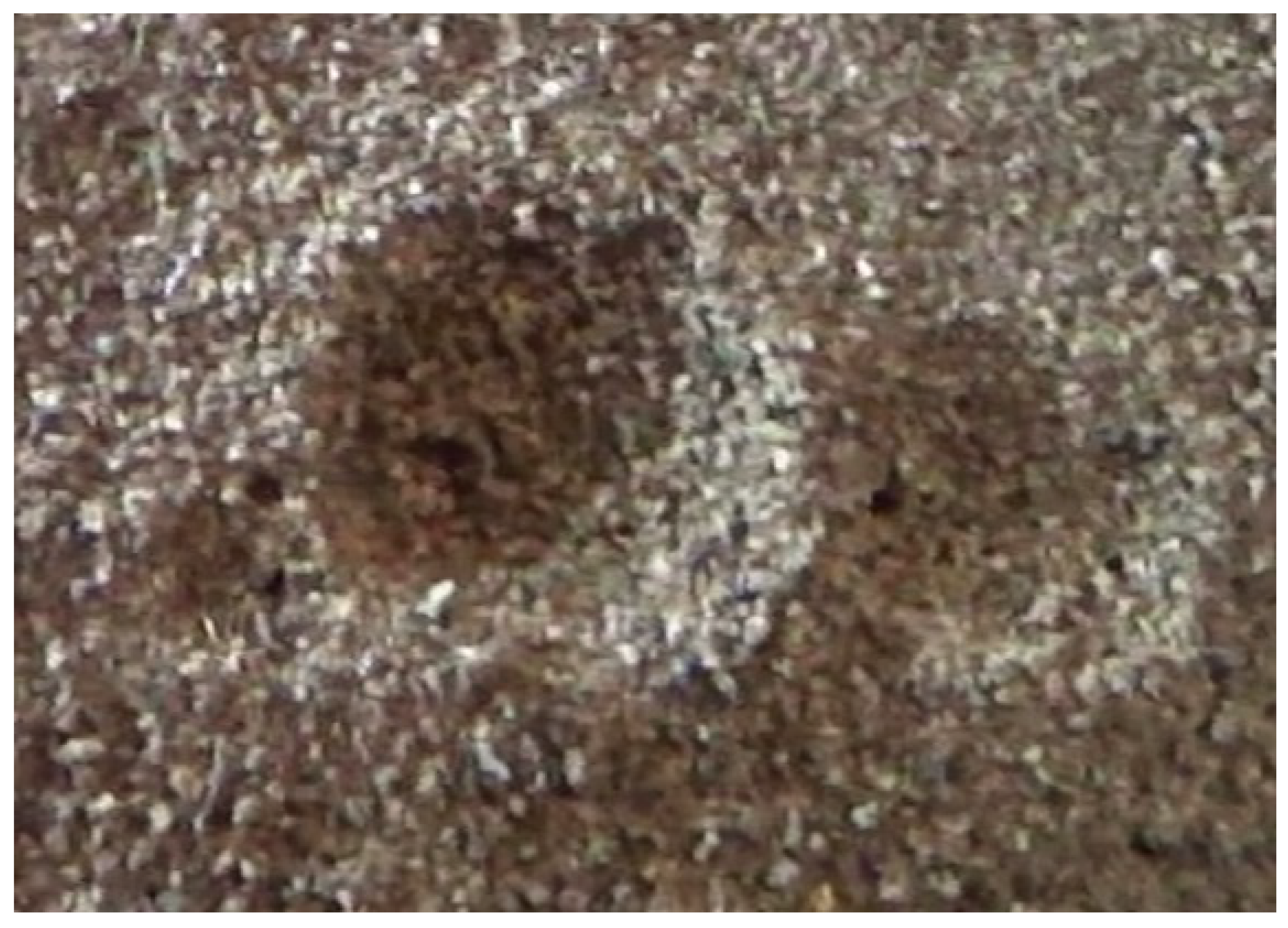
In our case an analog of the hypothetical transient cavity depicted by impact cratering theory (see Section 1.1.3 is the actual EDM source. In combination with low pressures, the EDM source maintains steady dimensions (having a decreasing current density until stable at ∼23 Torr) acting as a suitable “transient cavity” for excavation and gravitational collapse. Material is machined away from the surface, clearing a path to the cathode. Materials in the distal regions of the crater collapse under gravity and are machined out of the crater. The collapsing produces terracing and scalloping at the crater wall as material slumps forward (Figure 3 and Figure 4—[19]. Material can land on the crater wall, forming an elevated rim. Ridges can also form along the wall of the crater after collapse.
The presence of H2O plays a role in the result and duration of crater formation. Setups containing H2O can go on for some time, erasing collapsing features while forming a wide and barely visible depression.

4.1. Analogues

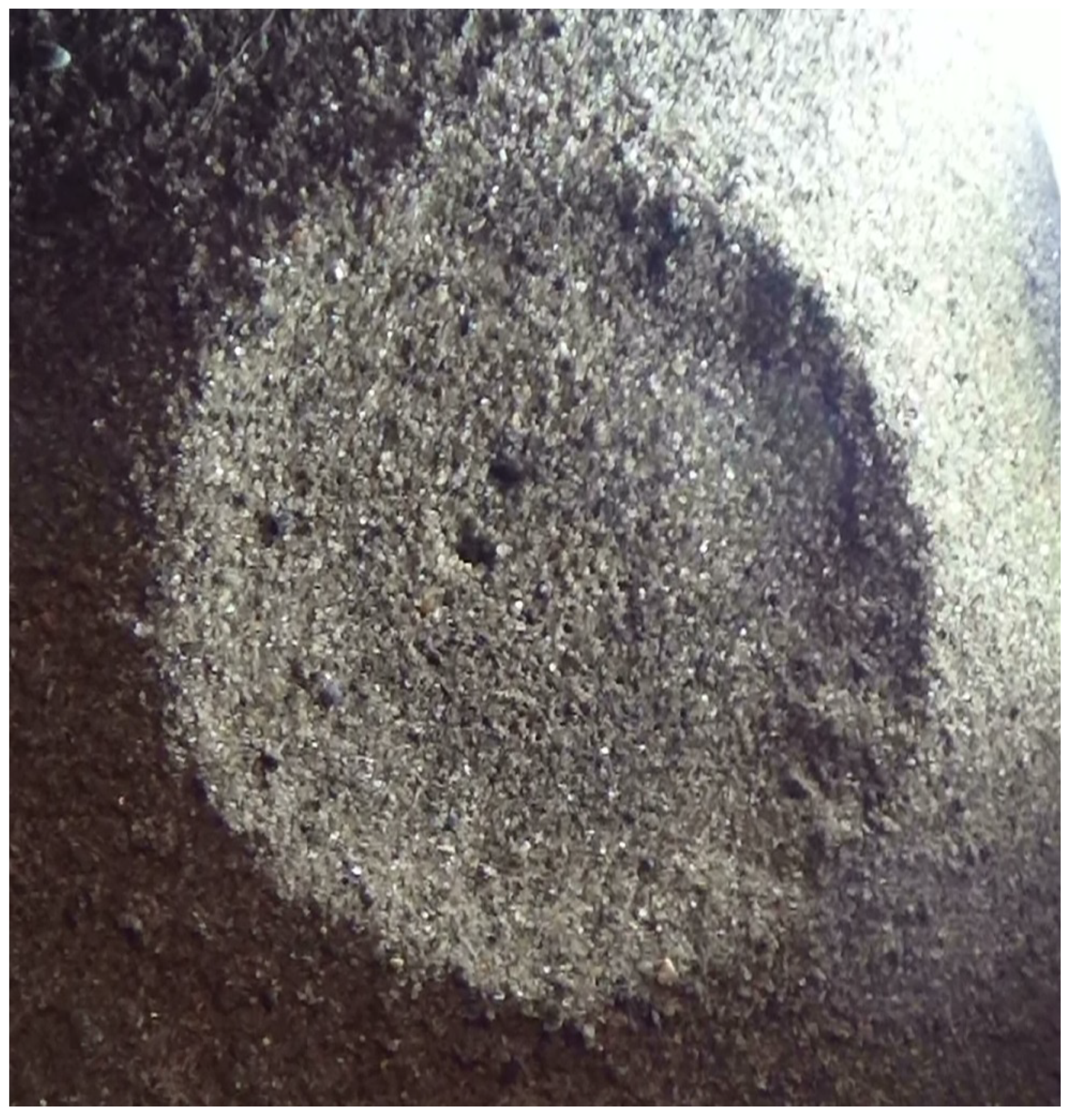
Many craters and other surface features produced by EDM as part of this research bear striking similarity to large scale surface features on planets and their satellites. Small formations are typically bowl shaped with raised rims (Figure 5). These formations will occur if the discharge duration is short or a conductive path is formed as mentioned in Section 3.1. It is also possible for several small craters to form a field (Figure 6). These fields can look analogous to fields of simple “secondary” craters. Smaller fields can produce craters side by side separated by distinct walls (Figure 7).
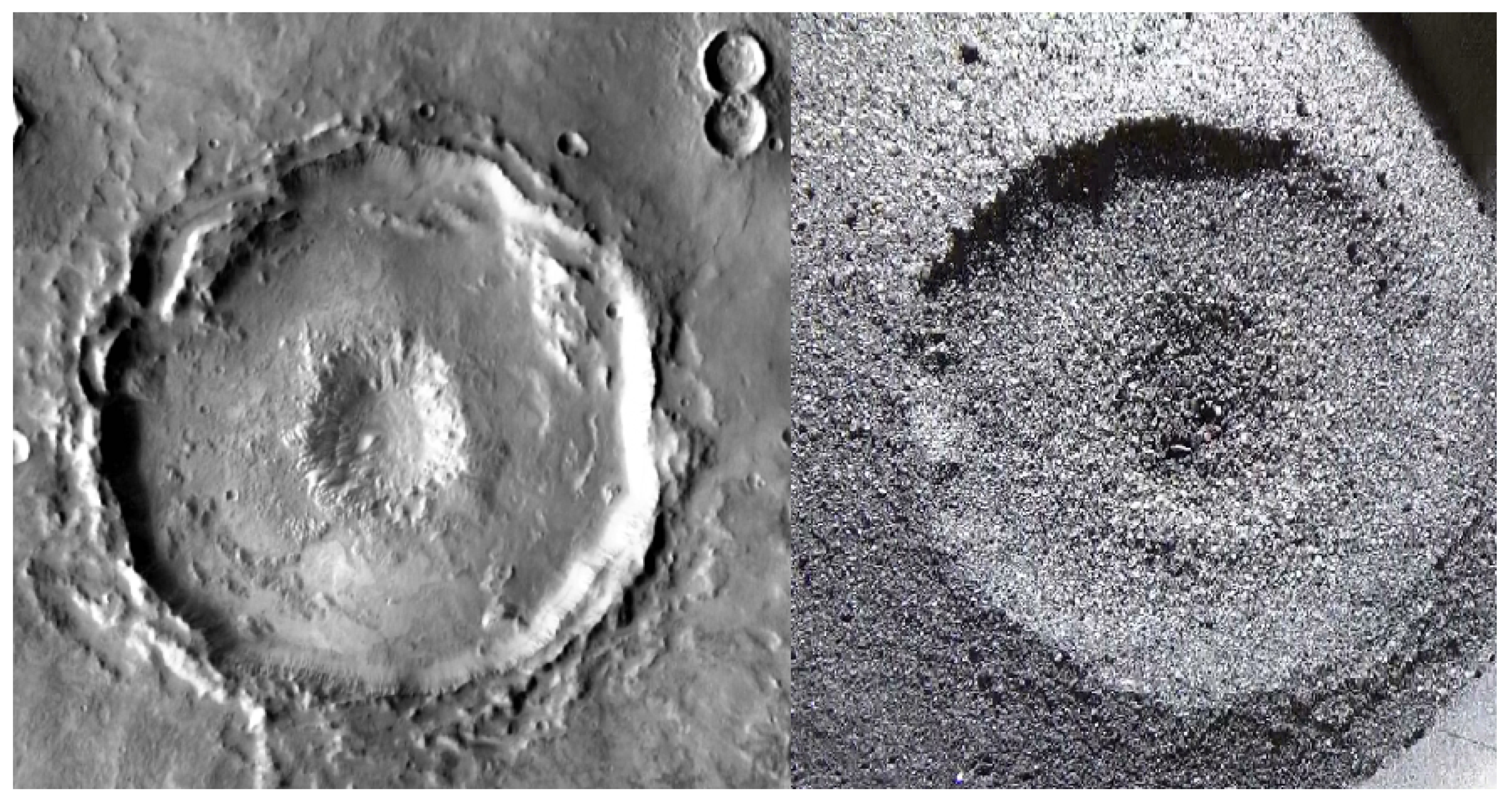
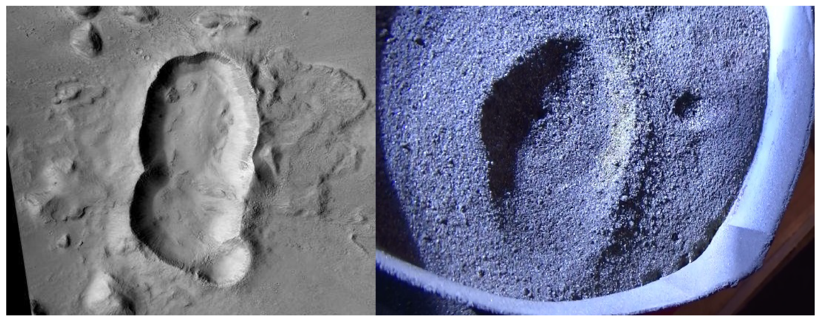
Larger formations will occur when the rim and walls repeatedly collapse under gravity producing terracing, scalloping, and ridges. These features can be accompanied by increasing levels of complexity, in one case resembling a complex crater with terracing/ridges, flat floor, central pit (with rim), darkening—Figure 8.
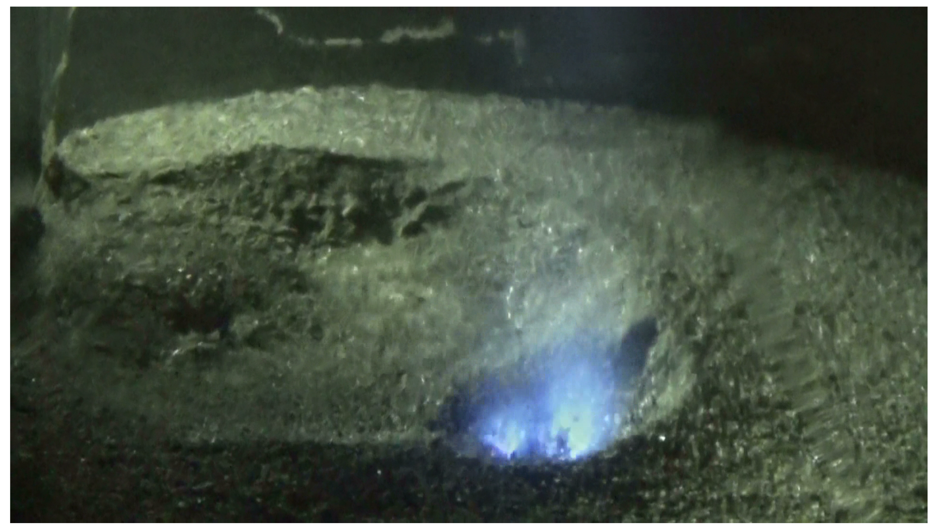
Another experiment suggests that a prolonged discharge can resemble several different formations throughout, but the final result might be a combination of some of them. This appears to be the consequence of craters forming in pairs (likely the result of pinching in plasma). EDM craters are often formed next to one another, but sometimes the discharge produced a single large crater with ridges. At one point the crater in [Video_1 file from Data Availability Statement] resembles a heart shape (Figure 9), examples of which are plentiful on Ceres and especially Mars. The resulting crater (diameter larger than 4–5 cm—Figure 10 was a large crater with another crater having formed on its rim. The craters also have straight edges and are intriguing examples of plasma producing features analogous to those observed on a larger scale.
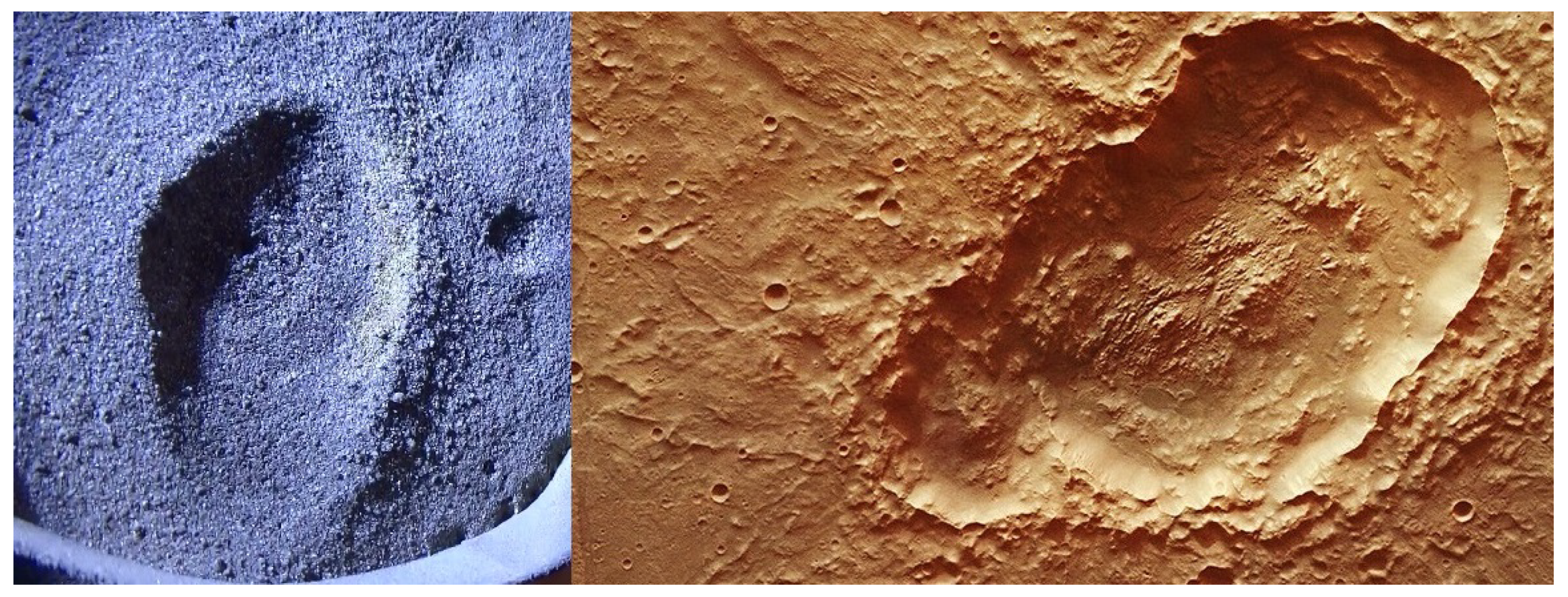
The discharge can move across the surface producing oblate formations. These formations are different from smaller fields mentioned earlier and are connected by a flat floor. The example provided also has an ejecta blanket that is strikingly similar to its “planetary” analogue (Figure 11 and Figure 12).
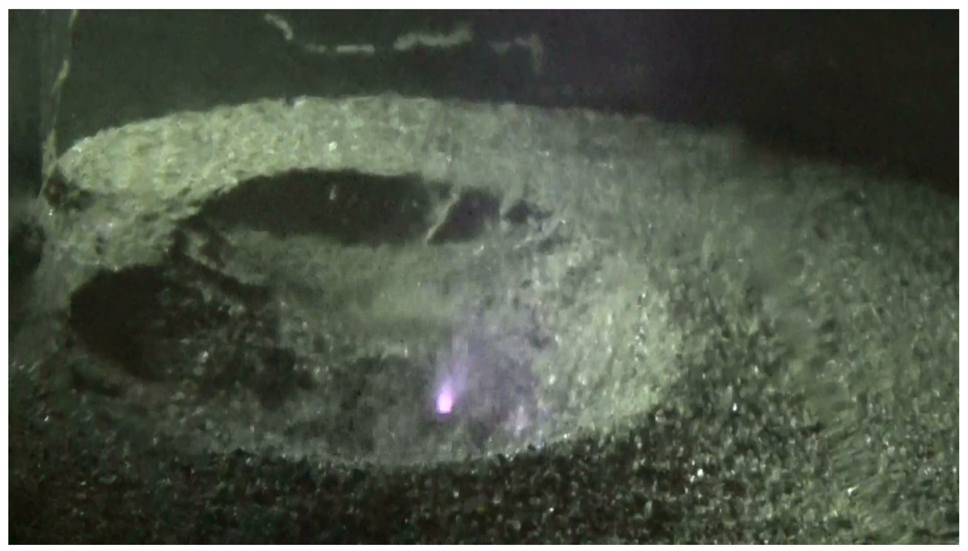
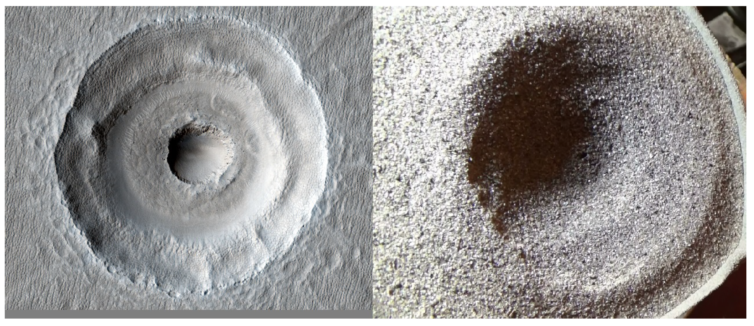
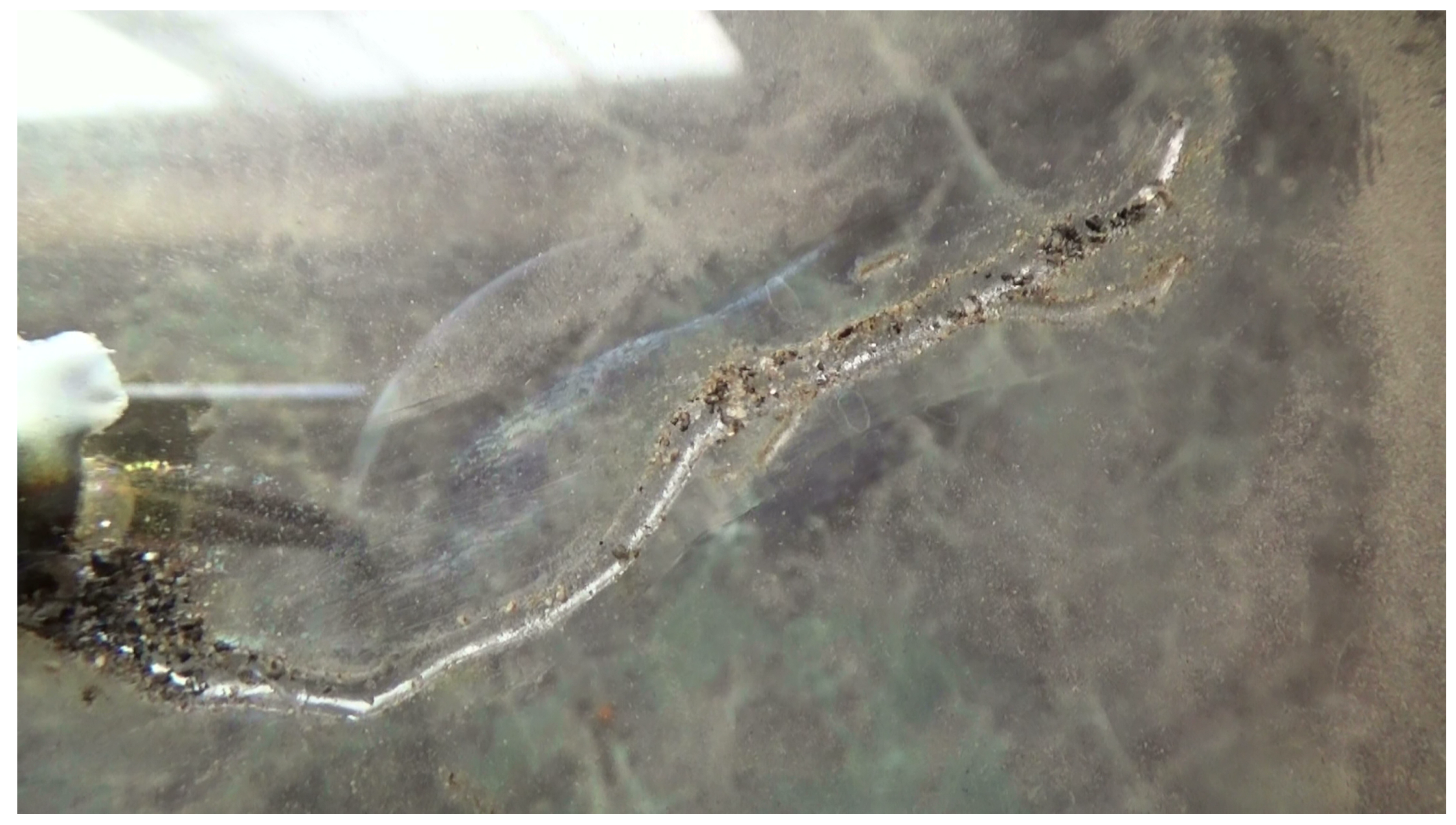
Higher amounts of H2O produce shallow depressions [video_2 file from Data Availability Statement]. Continued outgassing with the discharge obstructs detailed features. The features often resemble those seen on carbonaceous type asteroids such as Ryugu and Bennu. The discharge can machine a central pit within a crater. The central pit can grow in size, collapsing distal regions and increasing overall crater size. This process can occur several times forming multiple crater walls within the crater (Figure 13). A peculiar finding was an observation of a sinuous rille formed along the acrylic chamber that housed the experiment (Figure 14). This is notable as rilles are found on the lunar surface and may be evidence of the discharges associated with crater formation. Return samples taken from mission to a lunar rille (Apollo 15) found to contain green glass spheres [12]. As mentioned in Section 1.2, melted spheres are expected to form via electric discharge, and magnetism in rilles could be the remnant of electric currents flowing through the rock in the past.
Overall, the results fit rather well into the energy scaling law for crater sizes. Ref. [20] gives a general formula to estimate crater size D that corresponds to the energy T that is spent on its creation (with an “efficiency factor” ϵ ):
D = 10 2.924 ( ϵ T ) 0.3284
This formula is given in CGS units. In SI:
D = 10 2.6252 ( ϵ T ) 0.3284 .
In our case the energy is T 45 kJ (15 kV with 30 mA working for ∼100 seconds). Per formula (8—we shall take ϵ = 1 —this corresponds to a crater diameter of 8 cm, which is in incredibly good agreement with the actual results.

5. Discussion

It is worth noting that the process described in Section 1.1 heavily relies on simulations and purely theoretical considerations, as no experiments at comparable scales (with formation of, say, a 10 km sized crater) has ever been made. The correct scaling of laboratory impact experiments to geological sizes may prove to be problematic. Moreover, even on theoretical grounds it relies on one crucial part: the transient crater, the [at least brief] existence of which is assumed for all the impact craters. As such crater is, by definition, only transient, its existence cannot be proven, unless an actual cosmogenic crater formation process would be someday studied in great detail in real time. In this sense the EDM hypothesis seems equally as viable.

5.1. Mineralogical Evidence

One other issue of note is that a key piece of evidence for the purely impact based formation of craters, as follows from Section 1.1.2, is the presence of various shocked minerals. However, the very same effect can be produced by a strong electric current, as “... intense heat and pressure of impact events are similar to those experienced during lightning strikes” [21]. The similarity is so strong that the fulgurites are assumed to be the closest analogs to the products of an impact shock metamorphism [22,23], down to microscopic features such as shock lamellae in quartz [24].
In theory, there may be differences in redox states of minerals affected by electric currents and impact shocks, however, the studies of this issue demonstrate that both may lead to reduction [21] and in general the results are rather inconclusive. The same situation is with magnetization of minerals by impacts and electric currents: it seems that both can lead to magnetization [25,26,27], as well as demagnetization [28,29]—mostly due to intense heat—so the difference between the two is rather hard to pinpoint. The only obvious case where the magnetization could not have been caused by an impact and is most likely produced by electric currents is the sinuous rilles discussed in Section 1.2.
Cristobalite seems to be an interesting candidate for a “signature” mineral present in fulgurites [30], though some studies reveal that it’s only observed in younger samples, i.e. over time it relaxes back to quartz [31]. If there would be significant amount of evidence (for now there is not enough) that cristobalite is indeed the marker of electrically altered minerales, perhaps the fraction of cristobalite that has relaxed back into quartz might become a novel way to date an EDM produced crater. Overall, perhaps further research (which goes beyond the scope of this paper) would facilitate the search for detectable differences, so that impact and EDM hypotheses of crater production would be more distinguishable in terms of their mineralogical results.
There is some evidence for a strictly EDM mechanism of crater production, which comes from an inherently fractal nature of electric currents. For example, the microscopic structures of crystals taken from an “impact site” are “stringer”-like and shocked at the edges, whereas at the center they are more homogeneous and glassified [32], which mirrors a typical microscopic structure of fulgurites (Ende et al. [22]. The same (given fractality) can be observed on larger scale—for the craters themselves [33]. In this context, formation of “stringers” could be caused by the microscopic dendritic pattern of current itself rather than defects and structures in the mineral before the impact, as is assumed by some researchers [34]. It is curious that cristobalite (see above) is mostly formed at the edges [35], where we’d expect the current to go.

5.2. Comets and Asteroids

We might consider that asteroids and comets represent the material ejected from the surface of a larger planet during an EDM crater excavation. This is supported by the presence of hydrated minerals, carbonates [36] and clays [?] on comets and asteroids. Carbonates are minerals that form by precipitation from solution: the process of transforming dissolved substances into insoluable solids. This is generally understood to require liquids at atmospheric temperatures and pressures. The presence of carbonates on asteroid Bennu [37], for example, surely reveals problems concerning asteroid formation, mainly: where was the liquid water to produce carbonate veins? Considering an ejection hypothesis—asteroids, comets, and meteorites may have formed on larger bodies that may have contained atmosphere and liquids. In this case the presence of carbonates on asteroids and comets [38] isn’t difficult to explain, moreover, carbonates are also found in terrestrial craters [?], Martian craters, Occator crater on Ceres [39]. Furthermore the presence of strata and mesas on comet nuclei [40] continues to suggest a large atmospheric “parent” body. We could propose that smaller bodies came from larger bodies and formed “craters” upon their ejection, leaving EDM shocked and metamorphosed minerals in the affected bodies. This could even further be exemplified by the cases discussed in Section 4.1, in which the results were obtained from samples that contained higher amounts of H2O and resemble depressions on asteroids Bennu and Ryugu. H2O would manage carbonate formation in the atmosphere of large bodies, then continue to affect crater formation in the vacuum of space after ejection processes via outgassing and electric discharge.

5.3. Piezoelectricity

Piezoelectricity is another possibility for coupling of mechanical deformation of planetary surfaces (including crater production) with electromagnetic forces. E.g. it has been recently shown [41] that piezo effects are a viable method of power generation from the ambient mechanical vibration in an urban environment.
In the context of our study, we may consider a direct piezoelectric effect, where a deformation of the surface of a celestial body (regardless of its cause) may provoke the production of an electric field in it that would lead to a discharge and the formation of a crater. Likewise, a reverse piezoelectric effect may play its role, where an external electric field (e.g. the field of an infalling plasma cloud, as described in Section 3.1 and Section 5.4 would produce a mechanical deformation of the surface. It is hard to imagine an exact arrangement where such deformation would produce a crater, but it is possible that this mechanism might be involved in the production of various accompanying structures.
Understandably, the impact events proper might produce extreme electric potentials in the crust via the direct piezoelectric effect causing discharges during the compression and/or excavation phases (see Section 1.1.2Section 1.1.3. The presence of silicates on Mars and the Moon would accommodate this idea [?], silica being a crystal capable of the piezo effect. Same is true for quartz, which is extremely common on Earth.
Some studies of the Rochechouart crater, France [42], might lend support to EDM or piezo impact origins: “These minerals are of impact, not meteoritic, origin and probably formed by a combination of shock and plasma processes with the contribution due to each mechanism yet to be resolved”. Silicon carbide was among the minerals observed in the cited study. It is also found in fulgurites [43], comets, and meteorites (no confirmation on asteroids). Diligent study should be applied to consider any circumstantial evidence that might exist linking minerals such as silicon carbide to a possible impact/EDM hybrid process involving piezoelectricity.
For example, under the pressures of 100 GPa assumed for the impact (see Section 1.1.2 quartz—given its favorable orientation—would experience piezoelectric fields an order of magnitude larger than its breakdown strength:
E = q 2 ϵ ϵ 0 S = d 11 F 2 ϵ ϵ 0 S = d 11 P S 2 ϵ ϵ 0 S = d 11 P 2 ϵ ϵ 0 3 × 10 9 V m ,
where E is the strength of an electric field between two parallel surfaces with an area S within the quartz, q is the electric charge that appears on these surfaces, d 11 = 2.3 × 10 12 C/N [?] is the piezoelectric coefficient, F is the force acting perpendicularly to the surfaces, P is the pressure, and ϵ 4.5 is the dielectric permittivity. As we can see, it is an order of magnitude above the breakdown strength of quartz ( 5 × 10 8 V/m at 300 K—[44].
Hence an electric breakdown under the influence of an impact is likely. The reverse is not necessarily true (i.e. a simple electric breakdown is arguably not enough to replicate the results of an impact), yet this is another curious similarity between the two processes. To the best of our knowledge, none of the previous literature has taken these effects into account neither in the EDM nor in the impact cratering scenarios, whereas, as shown above, they may prove to be important for both.

5.4. Large Scale Craters

Here we shall consider the energies required to produce a large crater on the surface of a celestial body through the mechanism outlined in Section 3.1, as well as discuss the potential alternatives. To derive an upper boundary on the needed current we note that there are no craters larger than 104 km in the Solar System [?], and all the craters over a 103 km threshold are “basins” on the Moon and Mars. So we would use 103 km as a benchmark for the largest crater in the System. In order to produce such a crater, an energy of 1026 J is required [20]—see Formula (8) for an exact value.
Let’s consider a plasma cloud with flat parallel boundaries infalling perpendicularly on the surface (oriented parallel to the boundaries of the cloud itself). For an order of magnitude estimation we shall consider the following assumption: the energy available for the crater production is equal to the energy of the electric current, and thus is (per mechanism described in Section 3.1 of the same order of magnitude as the energy required to deviate the initial plasma cloud—i.e. its upper boundary is equal to the kinetic energy of the particles of the cloud itself (see (15) and further for a more comprehensive analysis). Hence
W = M v 2 2 ,
where W is the energy required for the crater production (here W = 10 26 J), M is the mass of the deviated particles, and v the cloud’s velocity. Obviously, M = m N = m n V , where m is the mass of a single particle (we shall assume they are protons, so m 10 27 kg), n is their number density ( n = N V ; N is the number of particles, and V is the volume of the cloud involved in the cratering process). In such consideration V L R 2 , where L is the cloud thickness, and R 2 is the surface area of the part of the cloud involved in the cratering. Clearly, R is of the same order as the crater/celestial body size ( R 10 6 m). Hence V 10 12 L .
Thus, our estimation of values in (10) leads to (we shall neglect the numerical coefficients and only focus on the order of magnitude factors):
10 26 m n V v 2 10 27 10 12 n L v 2 = 10 15 n L v 2 ,
or, expressing the parameters n L v 2 :
n L v 2 10 41 .
If we assume that the plasma comes from the Sun, then an obvious upper constraint on n L would come from an expression m n L r 2 α M , where r is the distance from the body to the Sun, M is the mass of the Sun, and 0 < α < 1 is the fraction of this mass that is carried away by the cloud. Hence n L α M m r 2 , or (taking r 10 11 m, i.e. an astronomical unit, so that m r 2 10 5 ):
α M v 2 10 36 .
Considering that M 10 30 kg, we arrive at α v 2 10 6 , or, in terms of α :
α 10 6 v 2 .
An obvious upper limit on v is the speed of light: v = c = 3 × 10 8 m/s, so the lower limit on the fraction of the Sun’s mass carried by the cloud is α = 10 10 . Currently observed coronal mass ejections may have velocities of the order of 0.01 c 10 6 m/s [45], which would correspond to a more realistic estimate of the mass fraction: α = 10 6 (this is the same order of magnitude as the mass of the Earth). Solar CME may have a mass from 10 10 kg up to 10 14 kg [46], though recent advancements in observational techniques have made possible measurements of plasma clouds with masses of 10 15 kg being ejected by Sun-like stars [47]. The upper figure of the given solar CME mass ( 10 14 kg) corresponds to the mass fraction of α C M E = 10 16 , hence the CME required for the production of the largest craters in the Solar System per mechanism described in Section 3.1 needs to be 10 6 10 10 times larger in terms of the mass carried away from the Sun.
To estimate how rare such an event may be, unfortunately, we can only rely on extrapolation of the present day in situ measurements of the solar plasma (e.g. based on the distribution characteristics presented in [48]. And following from these considerations such event is virtually impossible (according to our calculations, already for n 10 4 cm−3—whereas the actual densities required would be closer to n 10 13 cm−3—the expected frequency of occurrence is 10 9 yr−1, i.e. the corresponding time is of the order of the assumed age of the Solar System). Of course, due to the extremely short span of the observations (with respect to the assumed lifetime of the Solar System), not even including the well known extreme events of the last few centuries, such statistical estimation in meaningless. In principle, solar activity may have undergone significant changes during the evolution of the System, and we cannot exclude a higher (or even much higher) frequency of such events in the past.
Additionally, we shall note here that obviously these particular craters should not necessarily be the result of the cratering mechanism proposed in this paper. They might as well be the result of impacts. Our point, however, is to evaluate the possibility of even the largest craters being produced through the outlined mechanism.
Conversely, a strong modern day CME with a mass of 10 14 kg traveling at velocities of 1000 km/s would have total kinetic energy of 10 28 J, though only a tiny fraction of it would be accessible for cratering (determined by the size of the celestial body and its distance from the Sun). If we assume that the CME covers 1/4 of the heliosphere in directional sense (solid angle is equal to π ), then at distances of the order of an astronomical unit and the celestial body size of 10 6 m, the available energy would be determined by the solid angle taken by the body as seen from the Sun: Ω = π 10 12 10 22 = π 10 10 , hence only 10 28 10 J = 10 18 J is available for cratering. If all of this energy is being spent on the production of a single crater, the Formula (8) then determines its size as 2 km. This is a relatively large crater, which would be easily noticeable e.g. on the Moon or Mars, the surfaces of which are under constant observation of artificial satellites.
So we must conclude that not all of the CME energy is being spent on the cratering, so only smaller sized craters (if any) are produced by modern day CMEs. Perhaps the key point is that in order for the crater to appear through the outlined mechanism, the current has to be strong enough to undergo significant pinching (see Formula (6) and the following discussion), so that its thermal energy can be deposited in a localized manner. Hence only the stronger, fast and dense solar outbursts may lead to cratering. We have also omitted the consideration of other phenomena which may play a role in stronger CMEs: relativistic particle implantation being just one example.
On the other hand, a single energetic event may potentially produce multiple craters at once due to dendritic fractioning of the current into multiple branches (Figure 2 obviously only shows a single cross-section, whereas the event possesses a cylindrical symmetry with respect to the X axis, if we disregard the intrinsic plasma magnetic field as a symmetry breaker), which may also cause a polygonal shape in individual craters (see Section 5.5).
In [49] it was proposed that a strong CME in the Sun’s past could result in reduction of magnetic field strength. The decreased magnetic field would fail to deflect charged particles from the CME and solar wind. “... the incoming gas bringing its strong field into the virtually insulating atmosphere would then result in very large electric fields so directed that the resulting currents would maintain those fields”. These fields would lead to “electrical breakdown” on each side of the incoming CME cloud. “Hundreds of millions of amperes” would flow in the crust. It’s possible that smaller currents acting in lower pressures might machine for duration, producing a crater much larger than the plasma current may imply. Mars does indeed have a global electric current [50]. This current may have come under fluctuation in periods of increased solar activity [51] that might produce machining in the crust. In modern conditions the most obvious examples of continuous surface erosion under the influence of electric currents are observed in the magnetospheres of large planets: with electric currents flowing between Saturn and Enceladus [52] or Io and Jupiter [53] etc.
We acknowledge that a model of a solar storm presented in broad strokes in [49] in its essence is analogous to the scheme outlined in Section 3.1, but without the more specific analysis given therein. More recently, the same scenario was proposed to explain the tectonic uplift on the Earth itself [54], where the energies accessible to very strong CMEs [55,56] are transformed into heat, which alters the planetary surface.
The considerations given here, as well as the Section 3.1 are obviously over-simplified and potentially ignore some higher order effects and dynamic phenomena (e.g. plasma waves). As we’re dealing with plasma, the actual dynamics of the process might be extremely complicated. For example, we have ignored the fact that the CME cloud should be electrically polarized due to the influence of the magnetic field of the Sun itself [57]. Thus, an infalling plasma cloud would produce an electric field between the surface of the celestial body and its immediate surroundings (at the time of impact occupied by the cloud’s plasma), which may provoke an electric discharge between the two, as the charge carriers are provided by the cloud itself. This is another potential source for cratering, though a simplified analysis shows that it may only be significant if the magnetic field within the cloud would reach unrealistically high values.
E.g. for a typical CME cloud that is 3 × 10 10 m thick [58] the available volume of plasma is V = 10 28 cm3, and we shall estimate the energy available for cratering as E = Q U , where Q is the available charge ( Q = e n V ), and U is the potential difference (as for the measure of E, we still take the largest Solar System crater size estimate of 10 26 J, which follows from (8). Hence U = E Q = 10 26 e n 10 28 = 10 17 n . In terms of field strength this corresponds to (at the given cloud thickness) 10 7 n V/m, which should be equal to the product v B :
v B n = 10 7 .
Thus for the velocities of 10 6 m/s the product of magnetic field B (in T) and number density n (in cm−3) should be of the order of 10 (typically it is 10 9 for a calm solar wind and is assumed to be around 10−7 for a Carrington event CME—[59]. So in our case it should be extremely high, though it is somewhat facilitated by the fact that particle density, solar wind velocity and magnetic field strength are usually connected and may scale upwards together [48].
Likewise, we have omitted other potential sources of electric current energy deposition to the surface (such as the formation of plasmoids in the celestial body’s magnetotail and their subsequent migration towards the body itself or the interaction with neighboring bodies through solar plasma—e.g. in the case of the Moon, as described in [60], yet all these higher order effects may play a significant role at higher plasma energies required by our model.
Another thing we’ve ignored is the energy of the magnetic field of the plasma cloud, which may also theoretically be available for cratering, as the full energy of the cloud is the sum of its kinetic, electric and magnetic energies:
W = M v 2 2 + V ϵ 0 E 2 2 + V B 2 2 μ 0 = V 2 ( m n v 2 + ϵ 0 E 2 + B 2 μ 0 V 2 ( m n v 2 + B 2 μ 0 V ( 10 15 n + 10 6 B 2 ) ,
if we assume v 10 6 m/s. Only the first component was included in the initial estimation (10). The reason for this is that the second one heavily depends on magnetic field strength of the plasma and is typically 2–3 orders of magnitude smaller (e.g. in the case of a calm solar wind, where n 10 6 m−3, B 10 9 T), yet this may not be the case for more extreme situations (as has been demonstrated by [59] for Carrington event).

5.5. General Features

One peculiar piece of evidence of EDM cratering may be the polygonal shapes often observed in craters both on Earth and on other celestial bodies. As some researchers suggest (e.g. [61]), this may be caused by natural spacing of the smaller discharge channels (together making up the discharge as a whole), while it is extremely hard to explain in the impact formation approach without the introduction of ad hoc assumptions in each separate case.
Overall, the differences between EDM craters and impact craters have been summarized in [?], where the following traits are considered to be the decisive evidence towards EDM:
  • horizontal rim strata;
  • vertical walls coupled with a large completely flat floor;
  • an ejecta blanket system;
  • a central peak ring.
As follows from Section 1.1, an impact event may produce a single ejecta blanket layer, however, here the author specifically means a system of such with more than one overlapping layer, which is virtually impossible to achieve via an impact event.
Conversely, these, according to the cited source, are the traits of purely impact craters:
  • overturned rim layers;
  • a ray system or radiating ridges;
  • nickel-iron bodies embedded under the rim and shocked quartz in the crater;
  • a mascon associated with it.
In our opinion, Section 5.1 demonstrates that shocked minerals per se (including quartz—[24] cannot be the evidence neither for nor against an EDM nature of a crater, so the third feature should be reduced to only the first part.
Perhaps, recent developments in e.g. plasma blasting technology [62] would give useful insights into a more precise model of plasma-induced cratering of celestial bodies.

6. Conclusions

We develop a theory of electric discharge machining of planetary surfaces as a viable alternative to impact crater formation. It doesn’t directly contradict any of the observational evidence, while at the same time explaining some of the peculiar features that can’t be explained by impact hypothesis alone (e.g. polygonal craters or magnetization of sinuous rilles on the Moon). The scaled down experiment that we conduct as an illustration (where cratering is produced by plasma currents) serves as a perfect example of scalability of plasma processes, and may show how studies of large scale cratering could be done in cheap laboratory setups.
The low cost of the experiment and it’s effectiveness in reproducing the excavation and modification stages of crater formation might be useful even for impact studies—given essentially the same energy scaling Formula (8). Of course we know that impact cratering does occur, however the present study makes the case that the EDM mechanism is another viable option for crater formation, perhaps even more prominent in certain conditions (e.g. early Solar System).
Specifically, in this study we propose an extremely strong CME (106–1010 times larger than the present day CMEs1, or, alternatively, a plasma cloud from a nearby supernova) as a possible EDM source capable of producing even the largest craters in the Solar System (with all the the smaller ones being able to be electrically produced by much weaker events). An EDM mechanism allows to potentially resolve some long-standing problems in purely impact-based crater description (e.g. the existence of polygonal craters).
Regarding modern day CMEs, there is a potentially interesting avenue of further research: studying a possible correlation between CME arrival and the appearance of new craters on well studied surfaces. The Moon is the best candidate for this, as its surface has been mapped with good spatial resolution for almost two centuries [?]. Notable solar storms have occured in this timeframe, including the famous Carrington event of 1859. We haven’t yet been able to identify “new” craters that might be associated with it, as the task of comparing the older atlases with modern Moon maps is very labor-intensive, and historical accounts of finding new craters are rather sparse (e.g. [63]. It seems more fruitful to concentrate on the results from ongoing initatives such as NASA’s Lunar Impact Monitoring, operational since 2006 [?].
As an example, in 2013 the initiative has recorded the brightest flash since the start of the observations [?]. The event happened on March 17th and was assumed to be caused by an impact (the corresponding crater of 18 m in diameter was observed by Lunar Reconnaissance Orbiter in July of the same year). Yet this was the exact time when a plasma cloud from a strong CME (that happened on March 15th, 2013) has passed through the Earth–Moon system [?]. In our opinion, this might be more than just a coincidence.
Recent temporal observations of the Moon have already shown that the cratering rates there have been previously underestimated [64], which, we hypothesize, may be attributed to possible ongoing EDM cratering. Related electromagnetic effects could also account for at least some of the “transient lunar phenomena” [65]. The impact hypothesis is unfalsified in the absolute majority of related cases, as all of the impactors are assumed to be way too small to be detected prior to the impact, and hence their parameters are only constructed “out of nowhere” post hoc when the flash/crater is already visible, while our mechanism allows at least some degree of predictability—regarding the readings of the incoming interplanetary plasma. This paves the way for easily constructed further research on whether the new lunar craters could be related to easily observable interplanetary plasma parameters of randomly invented “impactors” for each separate case.
In this research we embrace the possibilities of plasma scaling with respect to crater formation. This allows for experimental small scale observation of the excavation and modification stages of what is presumed to be “impact” crater formation. Analogues of complex craters are produced, as well as a number of other features observed on crater scarred surfaces. The experiment that we propose and conduct is very easy to replicate and scale in either direction depending on the expermienter’s objectives. We have shown that even in the proposed crude setup it is easy to get meaningful results while maintaining control of the atmosphere, power source, and regolith. The upwards scaling is done through a theoretical consideration of the available current strengths and the energies released in an extremely strong solar outburst (taken as an example), while the energy needed is estimated with the same formula (8 that applies to all scales.
The most apparent implications of this experiment emerge in age determination of bodies. If craters are formed electrically, then determining the age of celestial bodies’ surfaces via “counting impacts” is erroneous. Additional studies might be done to determine the length and duration, or subsequent electric discharge events, but different bodies might respond differently even to a single event. This would imply that bodies farther away from the source may experience little EDM effects or none at all. Composition of planets and moons would also be an important factor, as different elements have different conductivities and chemical properties that alter formation processes slightly (another factor would be the influence from neighboring bodies, if any). The results also suggest a possibly rich field of study that exists almost wholly untapped.
The questions going forward should not be focused on verifying only one hypothesis of crater formation. The field of astrogeology would require diligent study of every crater to determine if they might be kinetic, electrical, or of a combined nature. Including new concepts and tools while adhering to the scientific method would prove beneficial to the field overall, despite enlarging the number of unknown parameters involved. The most significant changes would be the study of shocked and metamorphosed minerals, stages of crater formation, and theories regarding specific bombardment periods and timelines.
One problematic concept that stems from a purely impact-based crater formation is the “late heavy bombardment”, which is a period in Solar System history that is supposed to be unusually rich in terms of the number of impacts. Recently it has fallen under suspicion [66,?]. If at least some of the craters are electric in nature and may be produced by solar outbursts (or other similar phenomena such as an infalling cloud of plasma from a nearby supernova), it would mean that elevated levels of solar activity (or a nearby stellar activity) in the past would cause cratering on many planets at once, so e.g. no System-wide impact fiesta is required, which would explain the seemingly peculiar simultaneity of crater production during that epoch.

Data Availability Statement

All the imagery used in this study is available at the address: https://drive.google.com/drive/folders/1ck1210cYvt4d0It7b259y4ZZheE30YQa?usp=sharing.

References

  1. Bland, P. Crater counting. Astronomy & Geophysics 2003, 44, 4.21–4.21. [Google Scholar] [CrossRef]
  2. Melosh, H.J. Planetary Surface Processes, 1st ed.; Cambridge University Press: Cambridge, 2011; p. 534. [Google Scholar]
  3. Gifford, A.C. The mountains of the Moon. New Zealand Journal of Science and Technology 1924, 7, 129–142. [Google Scholar]
  4. Gifford, A.C. The Origin of the Surface Features of the Moon. New Zealand Journal of Science and Technology 1930, 11, 319–327. [Google Scholar]
  5. French, B.M. Traces of Catastrophe : A Handbook of Shock-Metamorphic Effects in Terrestrial Meteorite Impact Structures, 1st ed.; Lunar and Planetary Institute: Houston TX, 1998; p. 120. [Google Scholar]
  6. Ford, B.J. Origin of the lunar craters. Spaceflight 1965, 7. [Google Scholar]
  7. Ransom, C.J.; Thornhill, W. Plasma-Generated Craters and Spherules. IEEE Transactions on Plasma Science 2007, 35, 828–831. [Google Scholar] [CrossRef]
  8. Velázquez, V.F.; Gomes, C.B.; Mansueto, M.; de Moraes, L.A.; Sobrinho, J.M.A.; Lucena, R.F.; Sallun, A.E.; Sallun Filho, W. Morphological aspects, textural features and chemical composition of spherules from the Colônia impact crater, São Paulo, Brazil. Solid Earth Sciences 2021, 6, 27–36. [Google Scholar] [CrossRef]
  9. Hawthorne Jr., R. Electric Discharge - Not an Impact Caused Formation of Upheaval Dome, Canyonlands National Park, Utah. Journal on Systemics, Cybernetics and Informatics 2020, 18, 24–34. [Google Scholar] [CrossRef]
  10. Schumm, S.A.; Simons, D.B. Lunar Rivers or Coalesced Chain Craters? Science 1969, 165, 201–201. [Google Scholar] [CrossRef]
  11. Juergens, R.E. OF THE Moon AND MARS part I: The Origins Of The Lunar Sinuous Rilles. Pensée 1974, 4. [Google Scholar]
  12. Lakatos, S.; Heymann, D.; Yaniv, A. Green spherules from Apollo 15: Inferences about their origin from inert gas measurements. The Moon 1973, 7, 132–148. [Google Scholar] [CrossRef]
  13. Denevi, B.W.; Robinson, M.S.; Boyd, A.K.; Blewett, D.T.; Klima, R.L. The distribution and extent of lunar swirls. Icarus 2016, 273, 53–67. [Google Scholar] [CrossRef]
  14. Hemingway, D.J.; Tikoo, S.M. Lunar Swirl Morphology Constrains the Geometry, Magnetization, and Origins of Lunar Magnetic Anomalies. Journal of Geophysical Research: Planets 2018, 123, 2223–2241. [Google Scholar] [CrossRef]
  15. Kimura, H.; Mann, I.; Biesecker, D.A. Olivine and Pyroxene Dust Aggregates in Sungrazing Comets. Meteoritics & Planetary Science 2001, 36, A99. [Google Scholar]
  16. Schultze, D.S.; Jourdan, F.; Hecht, L.; Reimold, W.U.; Schmitt, R.T. Tenoumer impact crater, Mauritania: Impact melt genesis from a lithologically diverse target. Meteoritics & Planetary Science 2016, 51, 323–350. [Google Scholar] [CrossRef]
  17. Alfvén, H. Cosmic Plasma, 1st ed.; D. Reidel Publishing Company: Dordrecht, 1981; p. 164. [Google Scholar]
  18. Peratt, A.L. Physics of the Plasma Universe, 2nd ed.; Springer: New York, 2015; p. 430. [Google Scholar]
  19. Kenkmann, T.; von Dalwigk, I. Radial transpression ridges: A new structural feature of complex impact craters. Meteoritics & Planetary Science 2000, 35, 1189–1201. [Google Scholar] [CrossRef]
  20. Bond, J.W. On the relationships between impact crater diameters and projectile kinetic energy. The Moon and the Planets 1982, 26, 317–321. [Google Scholar] [CrossRef]
  21. Roberts, S.; Sheffer, A.; McCanta, M.; Dyar, M.; Sklute, E. Oxidation state of iron in fulgurites and Trinitite: Implications for redox changes during abrupt high-temperature and pressure events. Geochimica et Cosmochimica Acta 2019, 266, 332–350. [Google Scholar] [CrossRef]
  22. Ende, M.; Schorr, S.; Kloess, G.; Franz, A.; Tovar, M. Shocked quartz in Sahara fulgurite. European Journal of Mineralogy 2012, 24, 499–507. [Google Scholar] [CrossRef]
  23. Roberts, S.E.; Sheffer, A.A.; McCanta, M.C.; Dyar, M.D.; Sklute, E.C. Investigating Redox Change During Impacts. 50th Lunar and Planetary Science Conference 2019 (LPI Contrib. No. 2132), 2019. [Google Scholar]
  24. Gieré, R.; Wimmenauer, W.; Müller-Sigmund, H.; Wirth, R.; Lumpkin, G.R.; Smith, K.L. Lightning-induced shock lamellae in quartz. American Mineralogist 2015, 100, 1645–1648. [Google Scholar] [CrossRef]
  25. Sakai, H.; Yonezawa, K.; Kouno, Y.; Shindo, T. Propagation of Lightning Current Studied by Remanent Magnetization. IEEJ Transactions on Power and Energy 2013, 133, 694–699. [Google Scholar] [CrossRef]
  26. Begnini, G.S.; Tohver, E.; Schmieder, M. Fulgurites: a rock magnetic study of mineralogical changes caused by lightning. American Geophysical Union, Spring Meeting 2013, abstract ID: GP33A-07, 2013. [Google Scholar]
  27. Wasilewski, P.J. Shock remagnetization associated with meteorite impact at planetary surfaces. The Moon 1973, 6, 264–291. [Google Scholar] [CrossRef]
  28. Gattacceca, J.; Boustie, M.; Lima, E.; Weiss, B.; de Resseguier, T.; Cuq-Lelandais, J. Unraveling the simultaneous shock magnetization and demagnetization of rocks. Physics of the Earth and Planetary Interiors 2010, 182, 42–49. [Google Scholar] [CrossRef]
  29. Tikoo, S.M.; Gattacceca, J.; Swanson-Hysell, N.L.; Weiss, B.P.; Suavet, C.; Cournède, C. Preservation and detectability of shock-induced magnetization. Journal of Geophysical Research: Planets 2015, 120, 1461–1475. [Google Scholar] [CrossRef]
  30. Pasek, M.; Pasek, V. The forensics of fulgurite formation. Mineralogy and Petrology 2018, 112, 185–198. [Google Scholar] [CrossRef]
  31. Ferrière, L.; Koeberl, C.; Libowitzky, E.; Reimold, W.U.; Greshake, A.; Brandstätter, F. Ballen quartz and cristobalite in impactites: New investigations. In Large Meteorite Impacts and Planetary Evolution IV; Geological Society of America: 2010. [CrossRef]
  32. Yin, F.; Chen, M.; Sharp, T. A TEM Investigation of Formation Process of Coesite From the Xiuyan Impact Crater. 82nd Annual Meeting of The Meteoritical Society 2019 (LPI Contrib. No. 2157), 2019. [Google Scholar]
  33. Plescia, J.B.; Cintala, M.J. Impact melt in small lunar highland craters. Journal of Geophysical Research: Planets 2012, 117. [Google Scholar] [CrossRef]
  34. Yin, F.; Chen, M. Microtextures of Coesites with Different Occurrences from the Xiuyan Crater. 50th Lunar and Planetary Science Conference 2019 (LPI Contrib. No. 2132), 2019. [Google Scholar]
  35. Trepmann, C.A.; Dellefant, F.; Kaliwoda, M.; Hess, K.U.; Schmahl, W.W.; Hölzl, S. Quartz and cristobalite ballen in impact melt rocks from the Ries impact structure, Germany, formed by dehydration of shock-generated amorphous phases. Meteoritics & Planetary Science 2020, 55, 2360–2374. [Google Scholar] [CrossRef]
  36. Kaplan, H.H.; DellaGiustina, D.N.; Simon, A.A.; Hamilton, V.E.; Poggiali, G.; Barucci, M.A.; Reuter, D.C.; Lauretta, D.S. Detection of Pyroxenes on Bennu with the OSIRIS-REx Visible and InfraRed Spectrometer. Asteroid Science in the Age of Hayabusa2 and OSIRIS-REx, held 5–7 November, 2019 in Tucson, Arizona. LPI Contribution No. 2189, id.2056, 2019. [Google Scholar]
  37. Kaplan, H.H.; Lauretta, D.S.; Simon, A.A.; Hamilton, V.E.; DellaGiustina, D.N.; Golish, D.R.; Reuter, D.C.; Bennett, C.A.; Burke, K.N.; Campins, H.; Connolly, H.C.; Dworkin, J.P.; Emery, J.P.; Glavin, D.P.; Glotch, T.D.; Hanna, R.; Ishimaru, K.; Jawin, E.R.; McCoy, T.J.; Porter, N.; Sandford, S.A.; Ferrone, S.; Clark, B.E.; Li, J.Y.; Zou, X.D.; Daly, M.G.; Barnouin, O.S.; Seabrook, J.A.; Enos, H.L. Bright carbonate veins on asteroid (101955) Bennu: Implications for aqueous alteration history. Science 2020, 370, eabc3557. [Google Scholar] [CrossRef] [PubMed]
  38. Flynn, G.J.; Leroux, H.; Tomeoka, K.; Tomioka, N.; Ohnishi, I.; Mikouchi, T.; Wirick, S.; Keller, L.P.; Jacobsen, C.; Sandford, S.A. Carbonate in Comets: A Comparison of Comets 1P/Halley, 9P/Temple 1, and 81P/Wild 2. 39th Lunar Planetary Science Conference (League City, TX), 2008. [Google Scholar]
  39. Carrozzo, F.G.; Sanctis, M.C.D.; Raponi, A.; Ammannito, E.; Castillo-Rogez, J.; Ehlmann, B.L.; Marchi, S.; Stein, N.; Ciarniello, M.; Tosi, F.; Capaccioni, F.; Capria, M.T.; Fonte, S.; Formisano, M.; Frigeri, A.; Giardino, M.; Longobardo, A.; Magni, G.; Palomba, E.; Zambon, F.; Raymond, C.A.; Russell, C.T. Nature, formation, and distribution of carbonates on Ceres. Science Advances 2018, 4, e1701645. [Google Scholar] [CrossRef] [PubMed]
  40. Giacomini, L.; Massironi, M.; El-Maarry, M.R.; Penasa, L.; Pajola, M.; Thomas, N.; Lowry, S.C.; Barbieri, C.; Cremonese, G.; Ferri, F.; Naletto, G.; Bertini, I.; La Forgia, F.; Lazzarin, M.; Marzari, F.; Sierks, H.; Lamy, P.L.; Rodrigo, R.; Rickman, H.; Koschny, D.; Keller, H.U.; Agarwal, J.; A’Hearn, M.F.; Auger, A.T.; Barucci, M.A.; Bertaux, J.L.; Besse, S.; Bodewits, D.; Da Deppo, V.; Davidsson, B.; De Cecco, M.; Debei, S.; Fornasier, S.; Fulle, M.; Groussin, O.; Gutierrez, P.J.; Güttler, C.; Hviid, S.F.; Ip, W.H.; Jorda, L.; Knollenberg, J.; Kovacs, G.; Kramm, J.R.; Kührt, E.; Küppers, M.; Lara, L.M.; Moreno, J.J.L.; Magrin, S.; Michalik, H.; Oklay, N.; Pommerol, A.; Preusker, F.; Scholten, F.; Tubiana, C.; Vincent, J.B. Geologic mapping of the Comet 67P/Churyumov–Gerasimenko’s Northern hemisphere. Monthly Notices of the Royal Astronomical Society 2016, 462, 352–367. [Google Scholar] [CrossRef]
  41. Garimella, R.C.; Sastry, V.; Mohiuddin, M.S. Piezo-Gen - An Approach to Generate Electricity from Vibrations. Procedia Earth and Planetary Science 2015, 11, 445–456. [Google Scholar] [CrossRef]
  42. Hough, R.M.; Langenhorst, F.; Stoffler, D.; Pillinger, C.; Gilmour, I. Suevites from the Rochechouart Impact Crater, France, and the Lake Mien Impact Crater, Sweden: The Search for Robust Carbon Minerals. Meteoritics 1995, 30, 521. [Google Scholar]
  43. Hess, B.L.; Piazolo, S.; Harvey, J. Lightning strikes as a major facilitator of prebiotic phosphorus reduction on early Earth. Nature Communications 2021, 12, 1535. [Google Scholar] [CrossRef]
  44. O’Dwyer, J.J. The theory of dielectric breakdown of solids, 1st ed.; Clarendon Press: Oxford, 1964; p. 142. [Google Scholar]
  45. Chen, P. Coronal Mass Ejections: Models and Their Observational Basis. Living Reviews in Solar Physics 2011, 8. [Google Scholar] [CrossRef]
  46. Drake, J.J.; Cohen, O.; Yashiro, S.; Gopalswamy, N. IMPLICATIONS OF MASS AND ENERGY LOSS DUE TO CORONAL MASS EJECTIONS ON MAGNETICALLY ACTIVE STARS. The Astrophysical Journal 2013, 764, 170. [Google Scholar] [CrossRef]
  47. Namekata, K.; Maehara, H.; Honda, S.; Notsu, Y.; Okamoto, S.; Takahashi, J.; Takayama, M.; Ohshima, T.; Saito, T.; Katoh, N.; Tozuka, M.; Murata, K.L.; Ogawa, F.; Niwano, M.; Adachi, R.; Oeda, M.; Shiraishi, K.; Isogai, K.; Seki, D.; Ishii, T.T.; Ichimoto, K.; Nogami, D.; Shibata, K. Probable detection of an eruptive filament from a superflare on a solar-type star. Nature Astronomy 2022, 6, 241–248. [Google Scholar] [CrossRef]
  48. Larrodera, C.; Nikitina, L.; Cid, C. Estimation of the Solar Wind Extreme Events. Space Weather 2021, 19, e2021SW002902. [Google Scholar] [CrossRef]
  49. Gold, T. Large solar outbursts in the past. Pontificiae Academiae Scientiarum Scripta Varia 1962, 25, 159–174. [Google Scholar]
  50. Fränz, M.; Dubinin, E.; Maes, L. Electric current systems at Mars and Venus. Europlanet Science Congress 2020, online, 21 September–9 Oct 2020, 2020. [Google Scholar] [CrossRef]
  51. Paleari, C.I.; Mekhaldi, F.; Adolphi, F.; Christl, M.; Vockenhuber, C.; Gautschi, P.; Beer, J.; Brehm, N.; Erhardt, T.; Synal, H.A.; Wacker, L.; Wilhelms, F.; Muscheler, R. Cosmogenic radionuclides reveal an extreme solar particle storm near a solar minimum 9125 years BP. Nature Communications 2015, 13, 214. [Google Scholar] [CrossRef]
  52. Pryor, W.R.; Rymer, A.M.; Mitchell, D.G.; Hill, T.W.; Young, D.T.; Saur, J.; Jones, G.H.; Jacobsen, S.; Cowley, S.W.H.; Mauk, B.H.; Coates, A.J.; Gustin, J.; Grodent, D.; Gérard, J.C.; Lamy, L.; Nichols, J.D.; Krimigis, S.M.; Esposito, L.W.; Dougherty, M.K.; Jouchoux, A.J.; Stewart, A.I.F.; McClintock, W.E.; Holsclaw, G.M.; Ajello, J.M.; Colwell, J.E.; Hendrix, A.R.; Crary, F.J.; Clarke, J.T.; Zhou, X. The auroral footprint of Enceladus on Saturn. Nature 2011, 472, 331–333. [Google Scholar] [CrossRef]
  53. Peratt, A.L.; Dessler, A.J. Filamentation of volcanic plumes on the Jovian satellite Io. Astrophysics and Space Science 1988, 144, 451–461. [Google Scholar] [CrossRef]
  54. Johnson, R. Massive Solar Euptions and Their Contribution to the Causes of Tectonic Uplift. New Concepts in Global Tectonics 2014, 2, 16–36. [Google Scholar]
  55. Schaefer, B.E.; King, J.R.; Deliyannis, C.P. Superflares on Ordinary Solar-Type Stars. The Astrophysical Journal 2000, 529, 1026–1030. [Google Scholar] [CrossRef]
  56. Smith, D.S.; Scalo, J. Solar X-ray flare hazards on the surface of Mars. Planetary and Space Science 2007, 55, 517–527. [Google Scholar] [CrossRef]
  57. Alfvén, H. Cosmical Electrodynamics, 1st ed.; Clarendon Press: Oxford, 1950; p. 244. [Google Scholar]
  58. Shen, C.; Chi, Y.; Wang, Y.; Xu, M.; Wang, S. Statistical comparison of the ICME’s geoeffectiveness of different types and different solar phases from 1995 to 2014. Journal of Geophysical Research: Space Physics 2017, 122, 5931–5948. [Google Scholar] [CrossRef]
  59. Tsurutani, B.T.; Lakhina, G.S.; Echer, E.; Hajra, R.; Nayak, C.; Mannucci, A.J.; Meng, X. Comment on “Modeling Extreme “Carrington-Type” Space Weather Events Using Three-Dimensional Global MHD Simulations” by C. M. Ngwira, A. Pulkkinen, M. M. Kuznetsova, and A. Glocer. Journal of Geophysical Research: Space Physics 2018, 123, 1388–1392. [Google Scholar] [CrossRef]
  60. Jordan, A.P.; Stubbs, T.J.; Wilson, J.K.; Schwadron, N.A.; Spence, H.E.; Joyce, C.J. Deep dielectric charging of regolith within the Moon’s permanently shadowed regions. Journal of Geophysical Research: Planets 2014, 119, 1806–1821. [Google Scholar] [CrossRef]
  61. Burn, W. Polygonal crater formation by electrical discharges. New Concepts in Global Tectonics 2015, 3, 158–186. [Google Scholar]
  62. Kuznetsova, N.; Zhgun, D.; Golovanevskiy, V. Plasma blasting of rocks and rocks-like materials: An analytical model. International Journal of Rock Mechanics and Mining Sciences 2022, 150, 104986. [Google Scholar] [CrossRef]
  63. Nature Journal. A NEW CRATER ON THE LUNAR SURFACE. Nature 1878, 18, 197–198. [Google Scholar] [CrossRef]
  64. Speyerer, E.J.; Povilaitis, R.Z.; Robinson, M.S.; Thomas, P.C.; Wagner, R.V. Quantifying crater production and regolith overturn on the Moon with temporal imaging. Nature 2016, 538, 215–218. [Google Scholar] [CrossRef]
  65. Hughes, D.W. Transient lunar phenomena. Nature 1980, 285, 438. [Google Scholar] [CrossRef]
  66. Boehnke, P.; Harrison, T.M. Illusory Late Heavy Bombardments. Proceedings of the National Academy of Sciences of the USA 2016, 113, 10802–10806. [Google Scholar] [CrossRef] [PubMed]
1
perhaps, one could call it a sub-nova, as it’s 10 2 10 6 times weaker than a typical nova in terms of the fraction of M ejected
Figure 1. Pinhole channels. Pinhole sized channels form as a result of outgassing due to low atmospheric pressures. Outgassing may explain the observation of high porosity associated with low pressure bodies. If so, this would suggest a sudden loss of atmosphere in those bodies.
Preprints 66880 g001
Figure 2. Circiut model of a plasma beam interacting with a conducting surface. Plasma deceleration in the region DD’ causes an inertial current to appear which closes through the conducting surface and causes acceleration in the regions A and A’. The potential difference ranging from +V to −V in the beam is caused by the magnetic field of the plasma B. Reproduced from [17].
Preprints 66880 g002
Figure 3. EDM crater, fine material. Collapsing and terracing are a common feature of craters, resulting from gravitational slumping of material at the crater wall.
Preprints 66880 g003
Figure 4. EDM crater, scalloping and terracing. A close up of a terraced and scalloped crater wall.
Preprints 66880 g004
Figure 5. Small EDM crater. A small crater with a broad flat floor and ridges. Center left of the crater: larger channels are visible were the discharge became stagnant before being terminated.
Preprints 66880 g005
Figure 6. EDM crater field. A field of six craters of varying size, some sharing rims. It would be suspected these fields occur as a result of changing potentials at the surface, the discharge consequently taking the path of least resistance and forming several craters in the process.
Preprints 66880 g006
Figure 7. Three EDM craters sharing walls. A close up of three craters that formed in a field and share walls. The largest of them having a roughly 1 cm diameter.
Preprints 66880 g007
Figure 8. Complex crater comparison. Left: Arima crater on the Martian surface. Note the terraced wall, flat floor, central pit (with rim) and darkening around central pit. Right: EDM crater displaying remarkably similar features. Credit: JMARS/ASU/NASA.
Preprints 66880 g008
Figure 9. Dynamic EDM crater formation. This crater formed as a pair of craters throughout the discharge, changing in shape and size for roughly 10 minutes. Here we observe a proverbial heart shape that can also be found on celestial bodies.
Preprints 66880 g009
Figure 10. Dynamic EDM crater formation. The end result of the crater in Figure 9. When the discharge finally became stagnant, the end result was a straight edge crater with a smaller crater perched on the larger crater wall. As noted in Section 1.2, this feature is more common than what can be considered random and was a frequent result of EDM experiments.
Preprints 66880 g010
Figure 11. Oblate crater comparison. Left: an oblate crater from the Martian surface in the Elysium Planitia region. This formation contains what appear to be three craters that share a floor (rather than sharing walls—Figure 7. An ejecta blanket is on the right side of the formation. Also note a smaller grouping of craters, upper left in the image. Right: An EDM crater appearing as several craters sharing a floor, ejecta blanket on the right side and a smaller crater, also on the right of the main formation. Credit: ESA/DLR/FU Berlin, CC BY-SA 3.0 IGO.
Preprints 66880 g011
Figure 12. Oblate crater formation. Left: EDM crater from Figure 11. Right: A Martian formation from the Terra Sirenum region, similar to the formation from Figure 11. Note the ejecta blanket on the side of the formation. Credit: ESA/DLR/FU Berlin, CC BY-SA 3.0 IGO.
Preprints 66880 g012
Figure 13. Multiple walls comparison. Left: a crater from the Arcadia Planitia region, Mars, with multiple walls forming three concentric rings. Right: an EDM crater with several walls that formed by repeated collapsing and machining. Credit: NASA/JPL/University of Arizona.
Preprints 66880 g013
Figure 14. Sinuous rille in acrylic. A sinuous rille melted into the bottom of the acrylic chamber that housed the experiment. To the left of the image (not visible) is the cathode.
Preprints 66880 g014
Disclaimer/Publisher’s Note: The statements, opinions and data contained in all publications are solely those of the individual author(s) and contributor(s) and not of MDPI and/or the editor(s). MDPI and/or the editor(s) disclaim responsibility for any injury to people or property resulting from any ideas, methods, instructions or products referred to in the content.
Copyright: This open access article is published under a Creative Commons CC BY 4.0 license, which permit the free download, distribution, and reuse, provided that the author and preprint are cited in any reuse.
Prerpints.org logo

Preprints.org is a free preprint server supported by MDPI in Basel, Switzerland.

Subscribe

© 2024 MDPI (Basel, Switzerland) unless otherwise stated