Preprint
Article

Development and Application of Converter COMI-B Technology: A New Way of CO2 Utilization

Altmetrics

Downloads

174

Views

41

Comments

0

A peer-reviewed article of this preprint also exists.

This version is not peer-reviewed

Submitted:

05 February 2023

Posted:

06 February 2023

You are already at the latest version

Alerts
Abstract
CO2 has characteristic properties and reactions at converter smelting temperature, and the chemical reaction between CO2 and elements such as C and Si in the molten pool has bubble proliferation and cooling effects, which can effectively improve the kinetic and thermodynamic conditions of converter smelting. Here, an experimental study and industrial test on the application of CO2 in converter smelting were carried out. The smelting effects of Mode-1 and Mode-2 with total CO2 injection amounts of 229 Nm3 and 196 Nm3, respectively, were compared, and the changes in molten steel and slag compositions, dust removal, and gas are analyzed. The test results show that converter top and bottom blowing CO2 technology (COMI-B)technology had significant metallurgical advantages over the N-Mode; the dephosphorization rate increased by 4.2%, slag (FeO) content was reduced by 2.04%, end point nitrogen content of molten steel was reduced by 20%, gas recovery increased by 8.29 Nm3/t, and soot production reduced by 14.7%. The results of the study provide reference for the application of COMI-B technology in converters in the iron and steel industry and develop a new path for resource utilization of CO2.
Keywords: 
Subject: Engineering  -   Industrial and Manufacturing Engineering

1. Introduction

The iron and steel industry is transitioning from high-speed to high-quality development, and the innovation capability of converter smelting technology has been continuously enhanced, realizing low-carbon, low energy consumption and clean smelting convertors, and contributing to the rapid development of green and low-carbon products [1,2,3,4]. The industrial sector accounts for 33% and 40% of global energy consumption and CO2 emissions respectively, and the iron and steel industry contributes 33.8% of the industrial sector CO2 emissions [5]. Blast furnace-converters constitute the main and longest production process generating approximately 1.9 tCO2/t steel, and are worth considering in slowing down the carbon emission intensity. The capture and utilization of CO2 is crucial [6].
Recently, the reduction of CO2 emissions in the iron and steel industry has mainly involved three aspects: the upgrading of existing mature energy-saving technologies, the development and industrialization of key energy-saving technologies and the development and application of cutting-edge technologies [7,8]. Extensive studies on carbon emissions in the iron and steel industry have been conducted, mainly focusing on the use of CCS [9,10,11,12], CCU [13,14,15,16], and CCUS [17,18,19,20] to reduce carbon emissions. CCS technology includes three parts: carbon dioxide collection / capture, transportation, and storage, which focuses on storage after capture. Steeneveldt [21] pointed out that CCS depends on public acceptance and regulation of CO2 storage, reduction of CO2 capture costs, and adequate economic incentives. The difference between CCU and CCS is that CCU pays more attention to the utilization of CO2 after capture. Research and application results show that CO2 can be used in the chemical, agricultural and food industries, while the iron and steel industries can provide stable and clean CO2 raw material gas, assisting in promoting the utilization path of CO2 such as steel-chemical co-production and steel-agricultural carbon sequestration [22,23,24,25,26]. Valderrama introduced the preparation of oxalic acid and glycolic acid-based polyester materials from CO2 and analyzed its application potential [27]. Zhang proposed a method for the synthesis of ethanol from CO2, H2, lignin, or various aryl methyl ethers derived from lignin [28]. Chang studied the feasibility of combining CO2 capture with photobiological reactions (microalgae cells containing maximum spirulina) to remove some organic pollutants and nutrients from wastewater [29]. The capture and separation of CO2 is the prerequisite for its storage and comprehensive utilization, and it is also the focus of the research [30,31,32].
Research on the application of CO2 in the iron and steel industry has gradually increased in recent years. Owing to the gas characteristics, CO2 can be used in high temperature processes such as blast furnace, converter, and refining. Here, we mainly study CO2 resource utilization in a converter process. Researchers in the metallurgical field have conducted extensive research on converter top and bottom combined blowing oxygen, including the optimization of high efficiency oxygen supply of converter oxygen lance, converter bottom blowing layout and process optimization, etc., but there is limited research on the industrial application of converter top and bottom blowing CO2 technology (COMI-B). One of the main research directions of the author of this study has been the application of CO2 resources in converter steelmaking process for many years [33,34,35,36,37,38]. This study focused on experimental research on the application of COMI-B technology and converter smelting, and long-term industrial tests and applications were conducted. The participation of CO2 in metallurgical reaction and its metallurgical advantages were verified.

2. Carbon dioxide utilization principle

2.1. Reaction mechanism

Based on metallurgical thermodynamics software and research literature, CO2 is known to react with [C], [Si] and [Mn] in the molten pool in steelmaking temperature conditions, making it a weak oxidizing gas, as shown in Table 1.
Table 1 shows that both CO2 and O2 can react with the elements in the molten pool at steelmaking temperature, but there are two main differences between them when CO2 participates in the high temperature characteristics of steelmaking: (1) Kinetics: CO2 reacts with the elements in the molten pool to form CO gas, and 1 mol of CO2 reacts with C in the molten pool to form 2 mol of CO gas, while O2 only reacts with [C] to form CO gas and reacts with other elements to form compounds. Inert gases such as bottom blowing N2 or Ar do not have bubble proliferation effect. The chemical reaction of CO2 produces a large amount of CO gas, which has a bubble proliferation effect, helping to improve the stirring ability and kinetic conditions of the molten pool, and providing good kinetic conditions for dephosphorization, denitrification, and reduction of carbon and oxygen product. (2) Thermodynamics: Converter smelting is a process of oxidation heating, which is accompanied by a chemical reaction between O2 and the elements in the molten pool to achieve continuous heating in the converter smelting process, but O2 injection causes disorderly heating of the molten pool and iron evaporation to form a large amount of soot, which affects the dephosphorization efficiency and metal yield of converter smelting. The CO2 decarbonization reaction is an endothermic reaction, and although the reaction with Si and Mn is exothermic, it is only about 30% exothermic relative to the reaction of O2 with Si and Mn. The molten pool temperature can be controlled by injecting a certain proportion of CO2, which provides optimum thermodynamic conditions for dephosphorization. According to the energy balance calculation, when 5–15% CO2 is mixed into top-blown O2, the temperature of the hot spot of the molten pool decreases by about 300–500 ℃, which will reduce the evaporation of metallic iron and consequently reduce the production of steelmaking dust and increase the metal yield.

2.2. CO2 dephosphorization analysis

The dephosphorization reaction in the converter smelting process is a slag-steel interface reaction [39,40,41,42]. The degree of melting of slag and molten pool temperature in the early smelting stage (ES) have great influence on dephosphorization efficiency. Figure 1 shows the dephosphorization reaction between the elements in the molten pool and those in the slag at the slag-steel interface, which mainly includes the diffusion process of the reactants and products and the interfacial chemical reaction.
According to the viewpoint of slag molecular theory, the dephosphorization mechanism consists of the following reactions:
  2 [ P ] + 5 ( F e O ) + 4 ( C a O ) = ( 4 C a O · P 2 O 5 ) + 5 [ F e ]
The dephosphorization efficiency can be calculated according to the dephosphorization Formula (2).
lg ( % P ) [ % P ] = 12210 T 9.332 + 0.745 lg ( % T . F e ) + 2.358 lg ( % C a O )
Formula (2) shows that effectively increasing K, FeO, and % CaO is beneficial to the dephosphorization reaction. Therefore, improving the basicity and oxidizability of slag and reducing the temperature of molten pool are beneficial to improve dephosphorization efficiency. A comprehensive analysis of the influence of CO2 on dephosphorization in converter smelting indicated that CO2 has weak oxidation characteristics, and the dephosphorization reaction formula is shown in Table 1. A large number of CO bubbles after reaction can help to improve the stirring of the molten pool and accelerate the melting of slag, and the reaction between CO2 and C in the molten pool is endothermic, which can effectively control the heating rate of the molten pool by adjusting the amount of CO2. Therefore, CO2 is beneficial for converter dephosphorization.

2.3. CO2 denitrification analysis

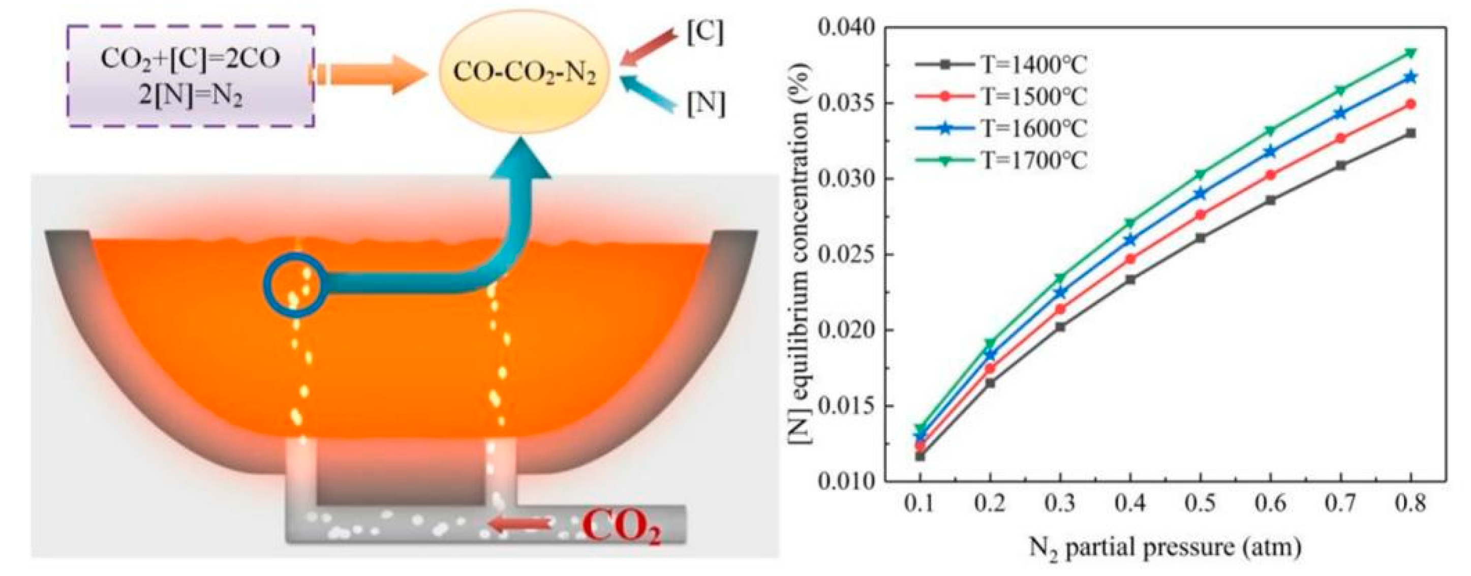
The main limiting steps of nitrogen removal from molten steel are as follows: (1) collision of [N] atoms, (2) combination of [N] atoms to form N2, and (3) diffusion of N2 to the interface. Under different conditions, the dissolution and escape of nitrogen is reversible. The solubility of N2 in steel obeys the square root law. At a certain temperature, N2 content dissolved in molten steel mainly depends on the partial pressure of N2 in the furnace gas, as shown in formula (3).
lg K N = lg P N 2 [ % N ] = 518 T 1.063
where, KN is the equilibrium constant; PN2 is the partial pressure of nitrogen in the furnace gas, atm.
Removal of N becomes difficult if the [N] content at the end point of converter smelting is low. Further control of the [N] partial pressure in the molten pool reduces the [N] in molten steel [43,44]. CO2 participates in converter smelting, and the proliferation effect of a large number of CO bubbles generated by CO2 reaction not only provides optimum kinetic conditions for the molten pool, but also reduces the partial pressure of [N], which is beneficial for [N] removal from the molten pool. Figure 2 shows the [N] equilibrium values of temperature and N2 partial pressure. The results show that increasing the bubble amount and decreasing the molten pool temperature are beneficial to the removal of [N]. Therefore, the addition of CO2 is valuable to further reduce the N content in the molten pool.

2.4. Analysis of soot production in steelmaking

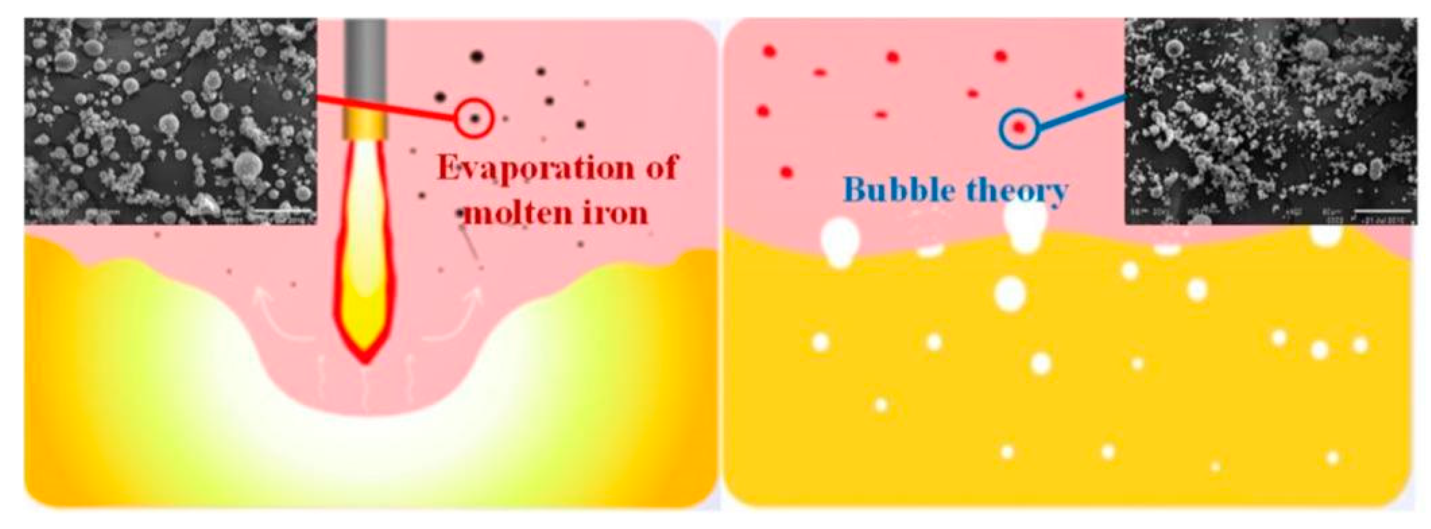
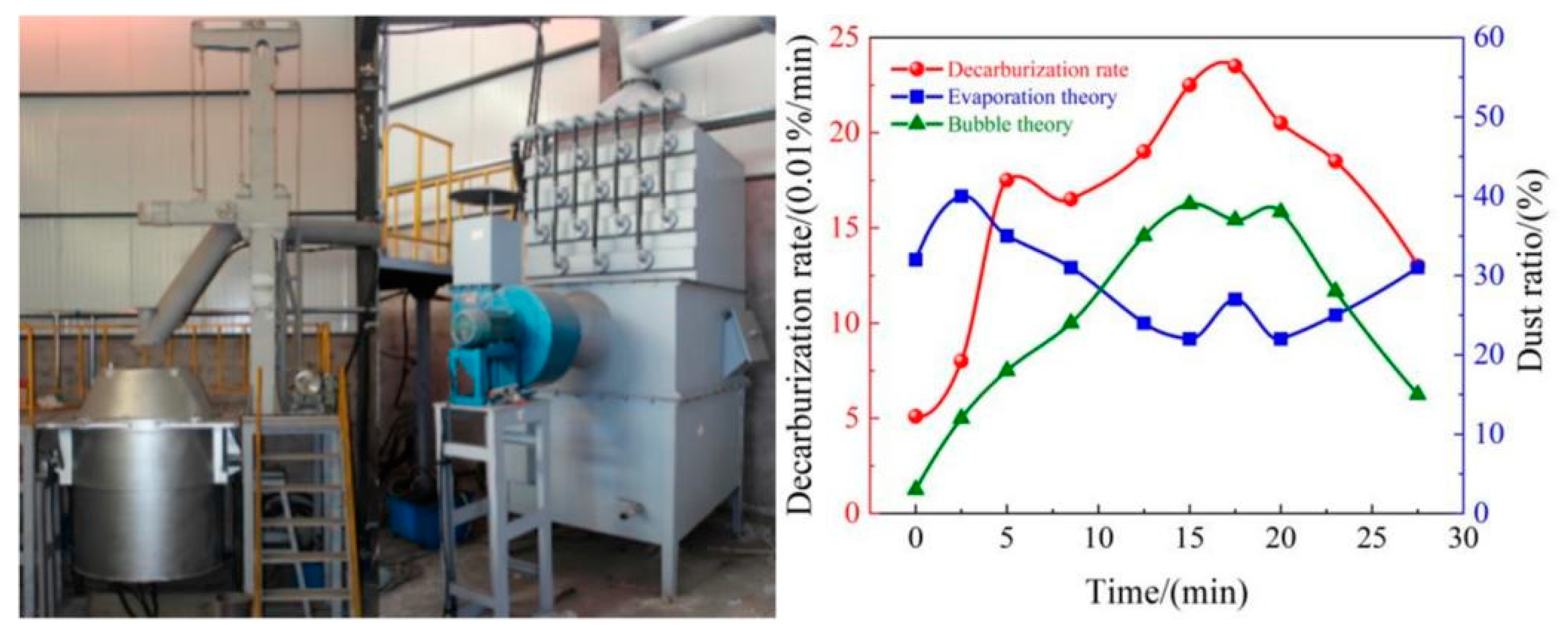
The supersonic oxygen jet contacts with the molten pool to form a high temperature fire zone in the converter smelting process, resulting in a large amount of molten iron evaporation that generates steelmaking dust, increasing the energy consumption and cost of pollutant treatment. The formation mechanism of steelmaking soot includes two models: the evaporation theory and bubble theory, as shown in Figure 3. The high temperature fire zone of the molten pool causes a large amount of metal iron to evaporate and oxidize. In the evaporation theory, when leaving the surface of the molten pool, part of the iron vapor is first oxidized and evolves into a nucleation core, and the rest of the iron vapor is gradually oxidized and grows in the rising process . In the bubble theory, a large number of CO bubbles float up during the molten pool decarburization reaction. When the bubbles break through the slag layer, surface potential energy is released and a small amount of metal iron and slag droplets spatter are produced through oxidation condensation. The formation mechanism affects the morphology and composition of soot. The soot particles formed by the evaporation theory are larger and relatively regular, while those formed by the bubble theory are finer and smaller with complex morphology.

3. Industrial tests

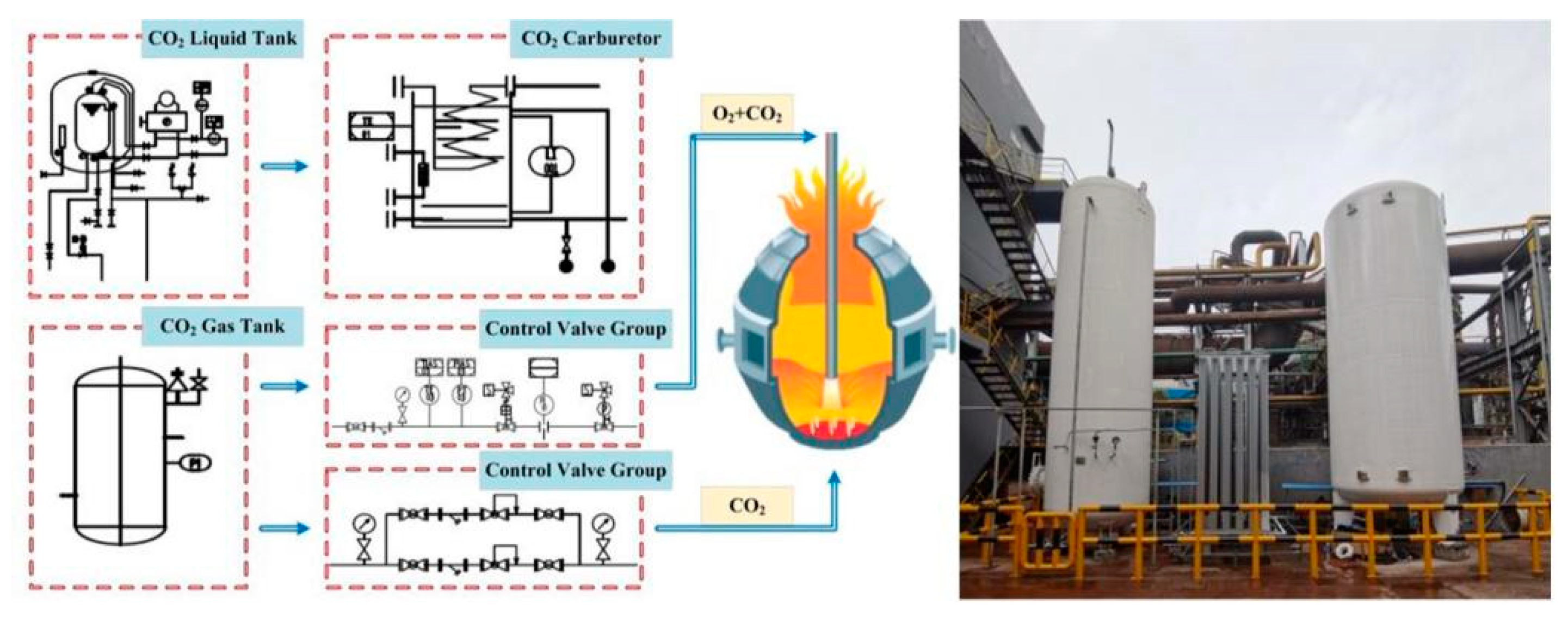
The content of this study is based on the industrial test data of COMI-B technology in a 120 t converter. The converter top blowing uses 4-hole oxygen lance nozzles with an outer diameter of 273 mm, average oxygen supply time of 12.5–13.5 min, gas supply intensity of top blowing O2 and CO2 of 3.5–4.1 Nm3/ (min∙t), and the mixing ratio of CO2 is 4% CO2 15%. Four elements were installed in the converter bottom blowing and distributed on the 0.6 D indexing circle. An asymmetrical arrangement was adopted and N2, Ar, or CO2 were blown at the bottom during the test. Different bottom blowing modes were set according to different smelting steels. The average air supply intensity was 0.03–0.07 Nm3/ (min t). The industrial test of 120 t converter COMI-B technology was conducted, and a total of 400 furnace industrial tests were undertaken. The technological process is shown in Figure 4, according to the comparative analysis of the smelting indexes of different converters.

3.1. Material conditions

The raw material conditions are shown in Table 2, in which the average amount of hot metal is 108.8 t, and the amount and proportion of scrap is 26.7 t and 19.7 %, respectively. A small amount of pig iron was added to some furnaces during the industrial test, to achieve the converter smelting heat balance, and its composition is listed in Table 2.
The slagging agent and coolant data added in the industrial test process are shown in Table 3. The slagging agent consisted of lime, light burning and raw dolomite, the coolant mainly consisted of limestone, ore and sludge balls. The slagging agent was divided into two portions that were added separately and the coolant was added all at once within 80 % of the oxygen supply time, as it cannot not be added in the later stage of smelting.

3.2. Injection mode

The industrial test CO2 was stably supplied by the gas source station, with a CO2 gas content of more than 99.5 %. The CO2 gas source pressure and flow rate were 2.0 MPa and 7000 Nm3/h, respectively, thus realizing the continuous and stable development of the industrial test process. To compare the metallurgical effect of the conventional and test furnaces, CO2 mixing flow rate of the oxygen lance top blowing was dynamically adjusted with oxygen cumulative consumption. The converter smelting process was divided into early (ES), middle (MS) and late (LS) smelting stages. The stage is outlined in detail in Table 4.
Based on the converter smelting process conditions, the CO2 mixing ratio is adjusted dynamically by stages, the flow rates in the ES, MS, and LS stages were 2300–3500 Nm3, 1400–2600 Nm3, and 2100–2800Nm3/h, respectively, divided into two top-blown O2 + CO2 modes. The original bottom blowing element was used in the test furnace, and the bottom blowing intensity was 0.03–0.07 Nm3/ (min∙t). The bottom blowing medium automatically switched N2, Ar, CO2, or CO2 mixture according to the type of steel. Two CO2 gas supply modes were designed in the industrial experiment, in which the total CO2 consumption of Mode-1 was 209 Nm3 and that of Mode-2 was 176 nm. The CO2 mixing ratio of Mode-1 was higher than that of Mode-2 in the ES stage, whereas it was the same in the MS and LS stages. In this study, the smelting effects of different gas supply modes of conventional furnace (N-Mode), Mode-1, and Mode-2 were compared. The main smelting steels in the test stage were low-carbon steel Q195Y and Q195L, and some medium and high carbon steel HRB400.

3.3. Experimental statistics and analysis

During the industrial test, the end point composition of molten steel consisting of O2, N and slag in N-Mode, Mode-1, and Mode-2 were selected to calculate the gas recovery and soot production. The recovery amount of converter gas and the production of smoke and dust were determined from the statistical data of the smelting system, and the consumption of iron and steel was calculated based on the addition of molten iron, scrap, pig iron, and tapping in the converter. The end point compositions of molten steel, consisting of [O], [N], and slag were taken from slag and steel samples before tapping of the converter, and the end point slag composition and molten steel composition were analyzed by fluorescence analysis and spectrometry.

4. Analysis and discussion of laboratory research and industrial test results

Based on the industrial test data of N-Mode, Mode-1, and Mode-2 models, the metallurgical effects of COMI-B technology applied to the 120t converter are compared and analyzed. The changes of converter dephosphorization efficiency, slag composition, [C] and [O] accumulation and end point [N] content of molten steel, gas recovery, and soot production are analyzed.

4.1. Dephosphorization efficiency

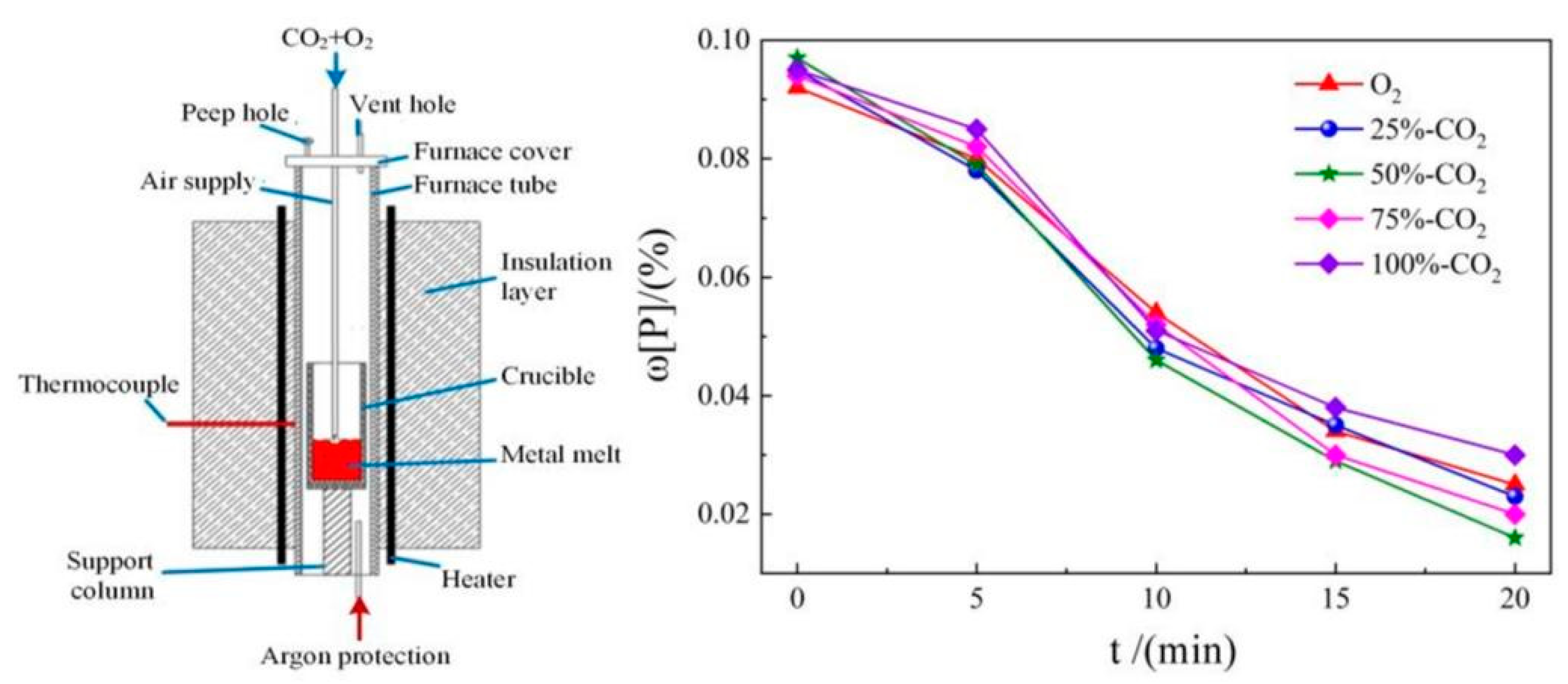
Here, the study of CO2 dephosphorization efficiency is based on the theoretical calculation and experimental research of FactSage thermodynamic software. Figure 5 shows dephosphorization efficiency changes of a high temperature experimental tube furnace and different CO2 proportions. A double platinum rhodium thermocouple is arranged at the bottom of the crucible and connected with a thyristor temperature controller, which can be used for continuous temperature measurement and control. CO2 and O2 are injected into the furnace from the top of the tubular furnace through the quartz tube, and Ar is injected from the bottom to protect the atmosphere in the furnace tube and crucible. As shown in Table 1, CO2 can react with phosphorus in the molten pool at 1573 K. With the progress of the smelting process, the phosphorus content in the molten pool shows a downward trend, and the dephosphorization efficiency is the highest when the mixing ratio of CO2 is 25%. After 5 min in the ES, Si and Mn are largely oxidized, and the dephosphorization rate increases significantly. From 5 to 10 min, the change of dephosphorization rate with the ratio of CO2 is small, indicating that under high phosphorus content in the molten pool, when the basicity, oxidizability, and temperature of the dephosphorization slag meet the dephosphorization requirements, the dephosphorization reaction is rapid and its rate is high. The dephosphorization rate with the CO2 mixing ratio of 25 % is still high, indicating that the appropriate CO2 mixing ratio can improve the dephosphorization efficiency.
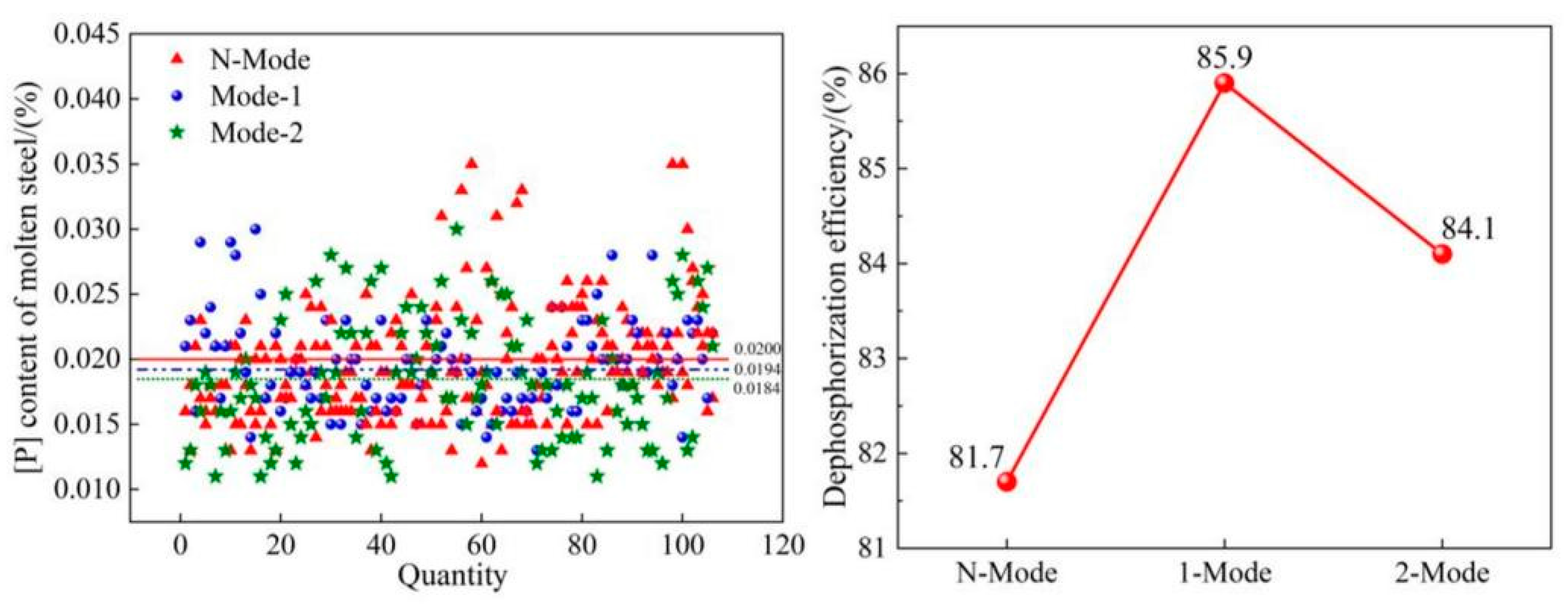
Figure 6 shows the end point phosphorus content and dephosphorization effect of 120 t converter industrial test. The results show that the P content of molten steel with Mode-1 and Mode-2 is 0.0194 % and 0.0184 % respectively, which is 0.0006 % and 0.0016 % lower than that of N-Mode, and the dephosphorization efficiency is 4.2 % and 2.4 % respectively, which are higher than that of N-Mode, indicating that the dephosphorization efficiency of molten steel using COMI-B technology is higher, and the dephosphorization efficiency of Mode-1 is the highest. It also shows that the appropriate CO2 mixing ratio is more beneficial to the dephosphorization reaction. The results shown in Figure 6 align to data in Table 1. CO2 is known to react with C elements in the molten pool to absorb heat, and injecting a certain proportion of CO2 can reduce the rate of temperature increase of the molten pool, providing optimum thermodynamic conditions for dephosphorization. At the same time, bottom blowing CO2 reacts with the elements in the molten pool to form CO bubbles, which has a bubble proliferation effect, helping improve the kinetic conditions of the molten pool. The reaction characteristics of CO2 are beneficial to improve dephosphorization efficiency. In addition, an appropriate CO2 injection ratio will help form high alkalinity slag in the ES stage, and further improve the dephosphorization efficiency. The addition of CO2 is conducive to the efficient and stable production of low phosphorus steel.

4.2. Slag composition and carbon and oxygen deposition of molten steel

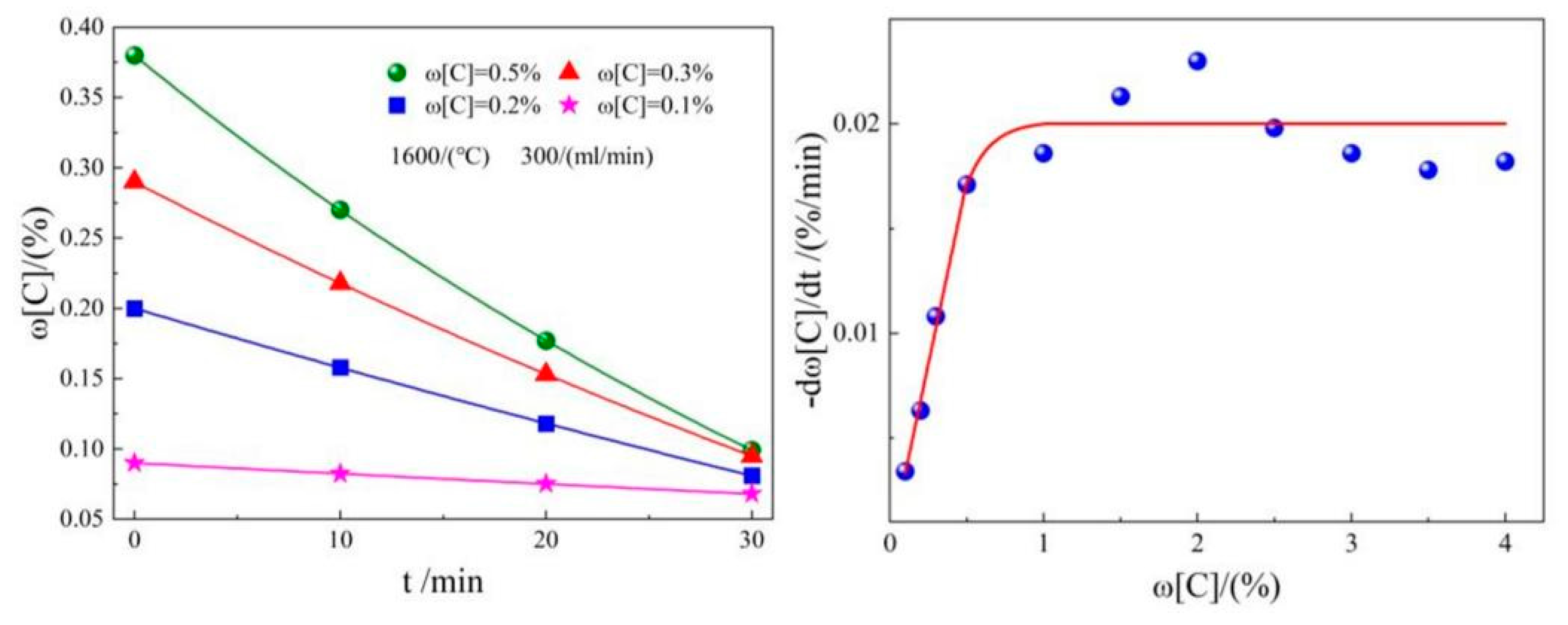
Figure 7 shows the effect of varying [C] content on the decarburization rate of injection CO2. The results show that with [C] content increase in molten steel, the decarburization rate of CO2 continues to increase, but when the [C] content gets close to 1%, the decarburization rate of CO2 is not enhanced and remains at a high level. The addition of CO2 can reduce the oxidizability of the slag and [C] and [O] accumulation of molten steel because CO2 can still achieve the decarburization effect in the converter during LS. Furthermore, although the amount of CO bubbles produced is less than that in the MS, the bubble volume is larger in the bottom blowing inert gas strengthening the stirring ability of the molten pool and the reaction area between steel and slag becomes larger and more sufficient. The O2 diffusion rate from molten steel to slag increases and the oxidizability of the slag simultaneously decreases.
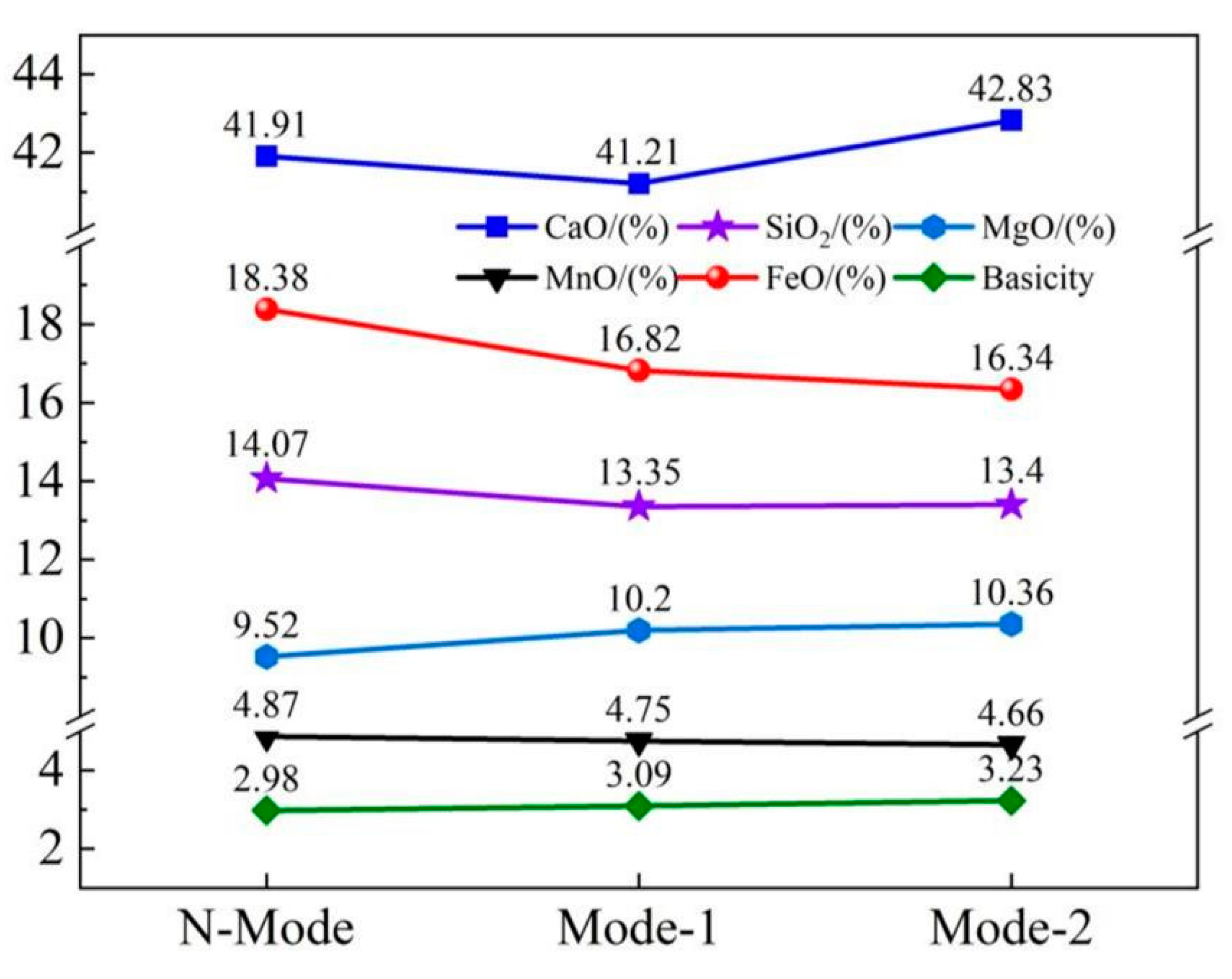
The influence of COMI-B technology on the composition of converter end slag is analyzed based on the test data. Figure 8 shows the changes of end-point slag composition under different modes. The results show that the mass fraction of end-point slag (FeO) in N-Mode, Mode-1, and Mode-2 is 18.38 %, 16.82 % and 16.34 %, respectively. The slag (FeO) content of Mode-1 and Mode-2 decreased by 1.56 % and 2.04 %, respectively, compared with the content of N-Mode. The results also show that the basicity of slag in N-Mode, Mode-1, and Mode-2 is 2.98, 3.09, and 3.23, respectively. Compared with the N-Mode model, the slag alkalinity of Mode-l and Mode-2 is 0.11 and 0.25 higher, respectively. Figure 8 shows that the main reason for this result is that CO2 reacts with various elements in the molten pool to form CO, which enhances the stirring of the molten pool, promotes the reaction at the slag-gold interface, reduces the oxidizability in the slag, and increases the metal yield.
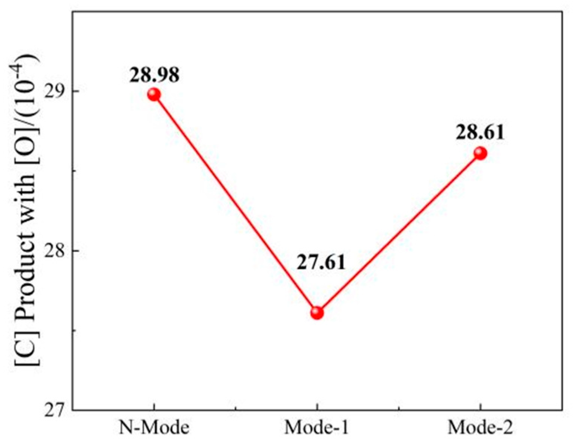
The value of the end-point carbon-oxygen product of molten steel not only represents the degree of peroxidation of molten steel, but also affects the yield of alloy and cleanliness of molten steel. Figure 9 shows the change in the end-point carbon-oxygen product of molten steel under different mode conditions. The results show that the end-point [C] and [O] product of molten steel in N-Mode, Mode-1, and Mode-2 is 28.98 × 10⁻⁴, 27.61 × 10⁻⁴, and 28.61 × 10⁻⁴ respectively. Compared with N-Mode mode, the end-point carbon and oxygen product of molten steel in Mode-2 and N-Mode is 1.37 × 10⁻⁴ and 0.37 × 10⁻⁴, respectively. The decrease in the end-point carbon-oxygen product of molten steel is mainly due to the chemical reaction between CO2 and elements in the molten pool to form a large number of CO bubbles, which promotes the reaction area between molten steel and slag and increases the [O] diffusion rate from molten steel to slag.

4.3. Nitrogen content in molten steel

For many types of steel, [N] is a harmful impurity that reduces the toughness, welding, and other properties of the steel, and should be entirely removed from steel [45,46]. The [N] in molten steel mainly originates from transferred metal material, slagging agent, air, and blowing gas medium. Currently, the production of low [N] steel mainly involves switching between N2 and Ar at the bottom or blowing Ar during the entire process. The speed control link of absorbing or precipitating N2 from molten steel mainly includes three speed control links:
(1) the gas diffuses to the surface of molten steel:
According to the mass transfer theory, the reaction rate is as follows:
v 1 = k N , g R T A V m ( P N 2 P N 2 * )
where, k N , g is the mass transfer coefficient of [N] in the gas phase, m/s; A is the reaction boundary area, m2; V m is the volume of molten steel, m3; P N 2 is the partial pressure of N2 molecules in the gas phase, Pa; P N 2 * is the partial pressure of N2 molecules on the surface of molten steel, Pa.
(2) adsorption chemical reaction:
N 2 * K K + 2 [ N ] * v 2 = d w [ N ] d t = A V m ( K + P N 2 * K w [ N ] *   2 )
where, K + is the rate constant of nitrogen absorption reaction, K is the rate constant of denitrification reaction, and w [ N ] * is the nitrogen content on the bubble surface.
(3) the diffusion of gas atoms in the molten steel:
[ N ] * [ N ] v 3 = d w [ N ] d t = k N , l A V m ( w [ N ] * w [ N ] )
where, k N , l is the mass transfer coefficient of [N] in the molten steel, and w [ N ] is the nitrogen content in the molten steel.
After finishing the formula, the rate equation of absorbing or precipitating N2 from molten steel is obtained, as shown in the following formula:
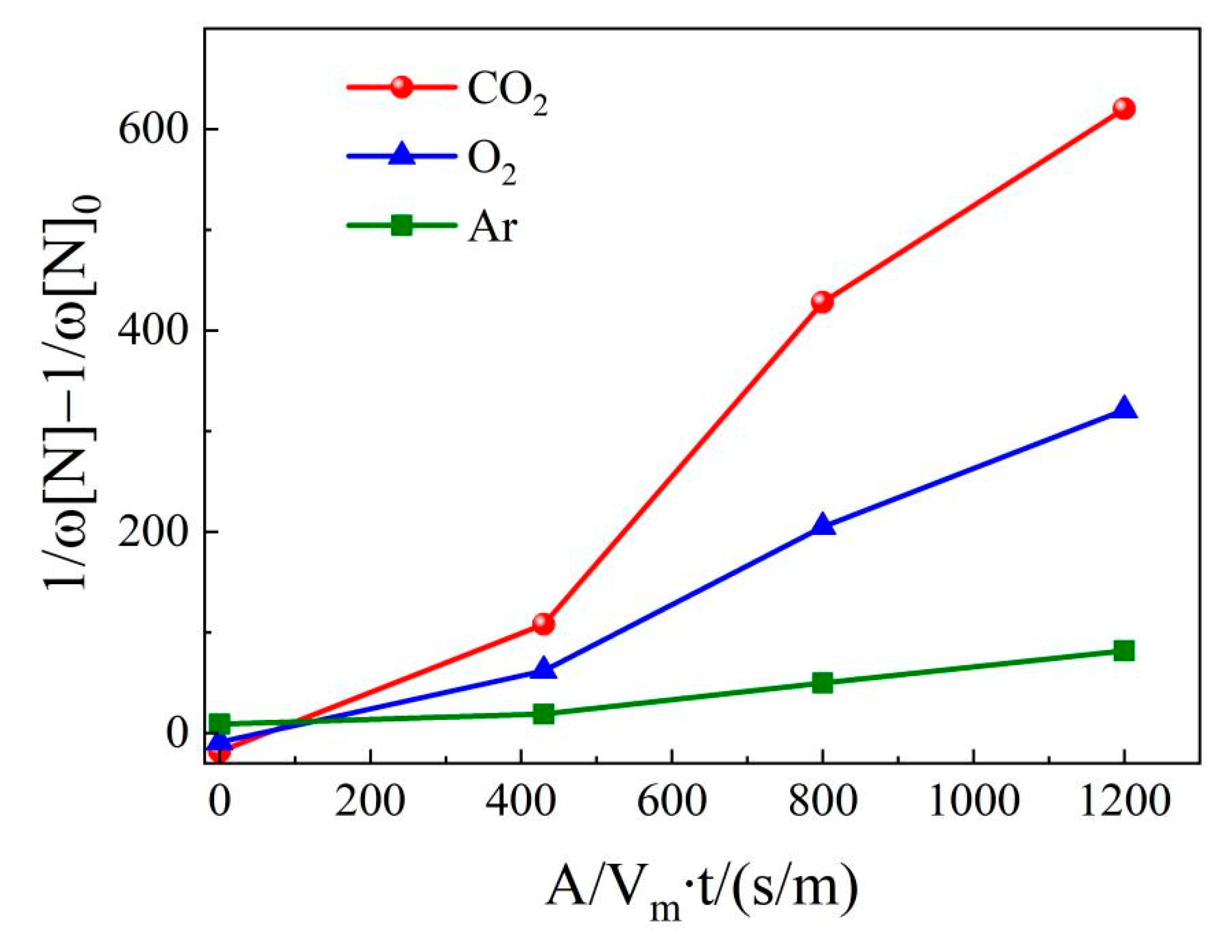
1 w [ N ] 1 w [ N ] 0 = K A V m t
where, w [ N ] is the nitrogen content in molten steel at t time, ppm; w [ N ] 0 is the nitrogen content in molten steel at initial time, ppm.
Draw with the left 1 w [ N ] 1 w [ N ] 0 coordinate on the left side of the formula (7) and the Abscissa on the right side of the A V m t circle, as shown in Figure 10. The rate constants of denitrification reaction in bottom blowing CO2, O2, and Ar are 1.15 m/s, 0.60 m/s, and 0.12 m/s, respectively. The denitrification rate constant in bottom blowing CO2 is 1.9 and 9.6 times higher than that in bottom blowing O2 and Ar, respectively. The reason is that a large number of CO bubbles are produced by bottom blowing CO2, which improves the denitrification capacity. The CO bubbles produced by CO2 reaction are dispersed in the molten pool, which can strengthen the stirring and make the bubbles discharge faster. Therefore, CO2 can be used as a bottom blowing source for smelting ultra low nitrogen steel.
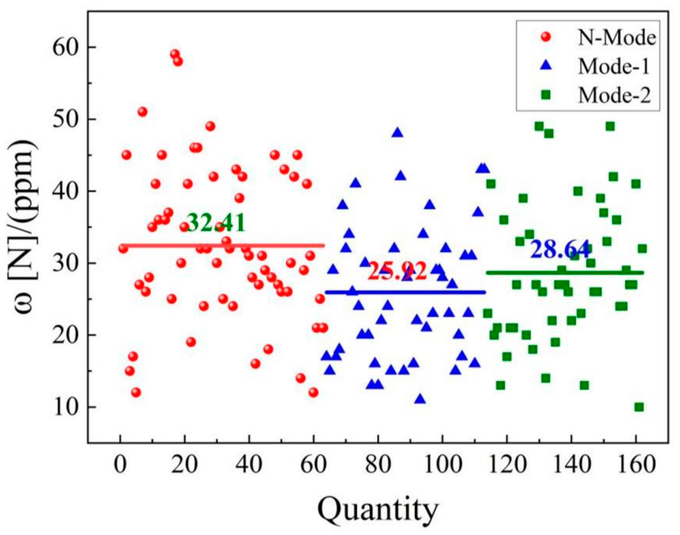
Figure 11 shows the change of end-point nitrogen content in molten steel under different mode conditions. The results show that the end point nitrogen content of molten steel in N-Mode, Mode-1, and Mode-2 is 32.41, 25.92, and 28.64 ppm respectively. Compared with Mode-2, the end N content of 6.49 and 3.77 ppm decreased by 20 and 11.6% respectively in N-Mode. Bottom blowing CO2 produces more CO bubbles, which enhances the stirring and bubble adsorption in the molten pool and accelerates the removal efficiency of nitrogen from molten steel.

4.4. Gas recovery

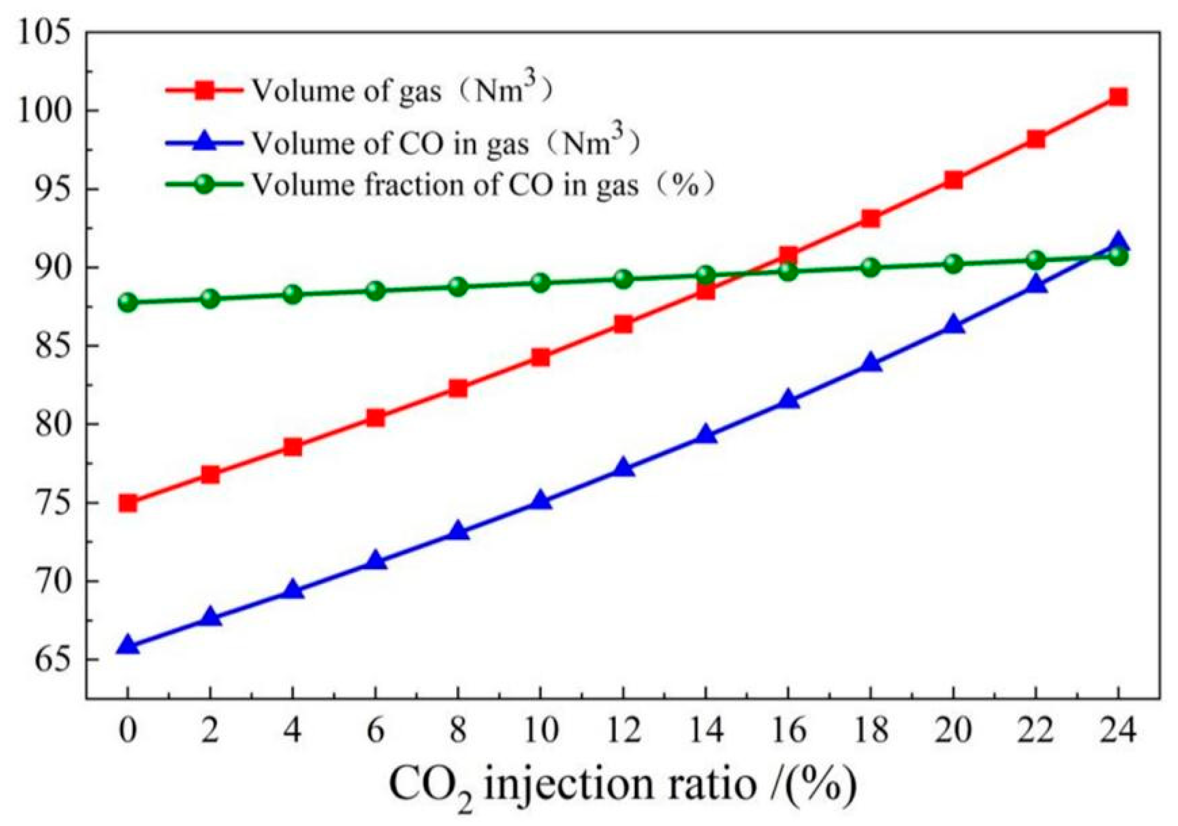
The calorific value and recovery of converter gas is an important energy index in converter smelting. The physical heat of converter gas can be used for preheating recovered steam and chemical heat can be used for ladle baking. Gas production and composition can be predicted from the material and energy balance of converter smelting. The results show that the furnace gas volume and CO volume in the furnace gas increased significantly with the increase of CO2 injection ratio (Figure 12). When the CO2 injection ratio increased to 23.5 %, the furnace gas volume increased from 75.0 to 100.24 m3, and the CO volume in furnace gas increased from 65.82 to 90.87 Nm3, but the volume fraction of CO increased by only 2.90%.
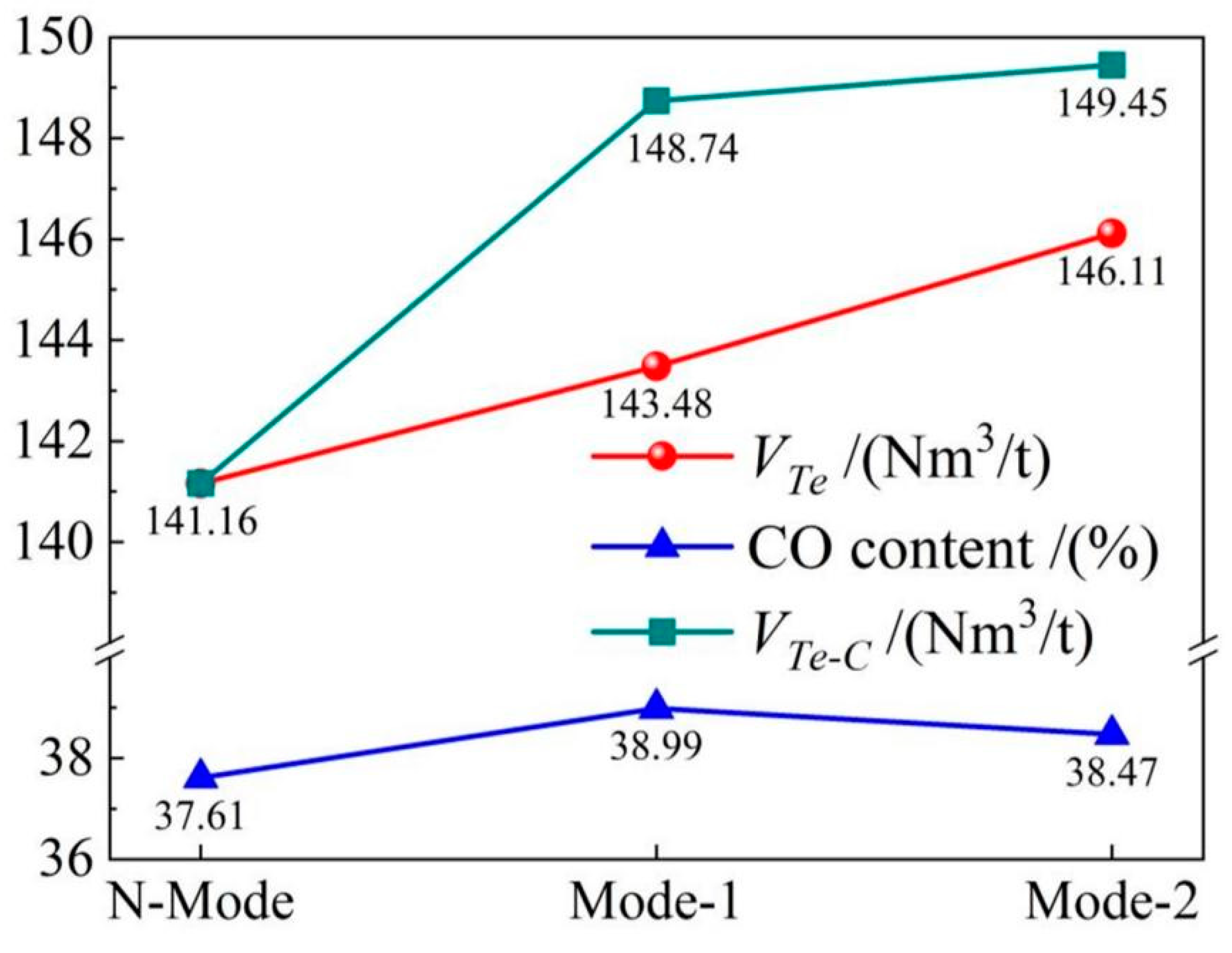
Based on the industrial test data of CO2 injection, the change in converter gas recovery under different mode conditions is analyzed. The results show that the per ton steel gas recovery of N-Mode, Mode-1, and Mode-2 is 141.16, 143.48, and 146.11 Nm 3 respectively. Compared with N-Mode, the per ton steel gas recovery capacity of Mode-2 increased by 2.32 Nm3 and 4.95 Nm3, in Mode-1 and Mode-2, respectively. The results also showed that the content of CO in Mode-1 was the highest, reaching 38.99 %, which increased by 1.38% compared with N-Mode. In order to analyze the comprehensive characterization of converter gas production and gas calorific value, the expression method of equivalent converter gas production is introduced. According to the ratio of CO content in Mode-1 and Mode-2 to CO content in N-Mode, the gas production compared with N-Mode model is calculated, and the mathematical expression is as follows:
V T e C = V T e × C T e C C o n
where, V T e C gas consumption is the equal calorific value of gas in Mode-1 and Mode-2 models relative to N-Mode models, Nm3/t; V T e is the actual gas production in Mode-1 and Mode-2 models, Nm3/t; C T e and C C o n represents gas CO content in Mode-1, Mode-2, and N-Mode,%.
Based on the formula, the per ton steel gas recovery of Mode-1 and Mode-2 models is 148.74 Nm3 and 149.45 Nm3, respectively, compared with N-Mode mode, the ton steel gas recovery volume increased by 7.58 Nm3 and 8.29 Nm3, respectively, and the gas recovery volume increased by 5.4% and 5.9% respectively, as shown in Figure 13. The main reason for the increase of gas recovery and calorific value in the experimental mode is that CO2 reacts with elements in the molten pool to form a large amount of CO, and 1 mol of CO2 reacts with carbon in the molten pool to form 2 mol of CO, which realizes the common improvement of gas quality and quantity.

4.5. Soot production

The enhanced O2 supply in converter smelting is the core process of modern steelmaking, and the supersonic oxygen jet forms a high temperature fire zone with the molten pool in the smelting process, whose temperature exceeds the boiling point of iron. Therefore, the steelmaking process forms a mixture containing a variety of discrete metal oxide particles due to iron evaporation, that is, steelmaking dust. The standard iron-carbon melt was prepared by melting industrial pure iron and high purity pig iron, and the hot experimental study on the mechanism of oxygen steelmaking soot was undertaken in 500 kg experimental converter, as shown in Figure 14. The reaction rate of C and O2 in the molten pool and the changing process of the particle size, composition, and morphology of steelmaking dust during converter blowing are tracked. The results show that in the ES stage, the C and O2 reaction is limited, and the soot and iron loss are mainly derived from the evaporation of a large amount of metallic iron caused by high temperature in the hot spot of the molten pool, while in the MS stage, a large number of CO bubbles are produced in the decarburization reaction, which aggravates the boiling of the molten pool and carries a large number of fine broken particles in the smoke. In the LS stage, with the decreased C content in the molten pool, the amount of CO bubbles produced by the decarburization reaction decreased sharply, and the soot and iron loss were mainly caused by iron evaporation.
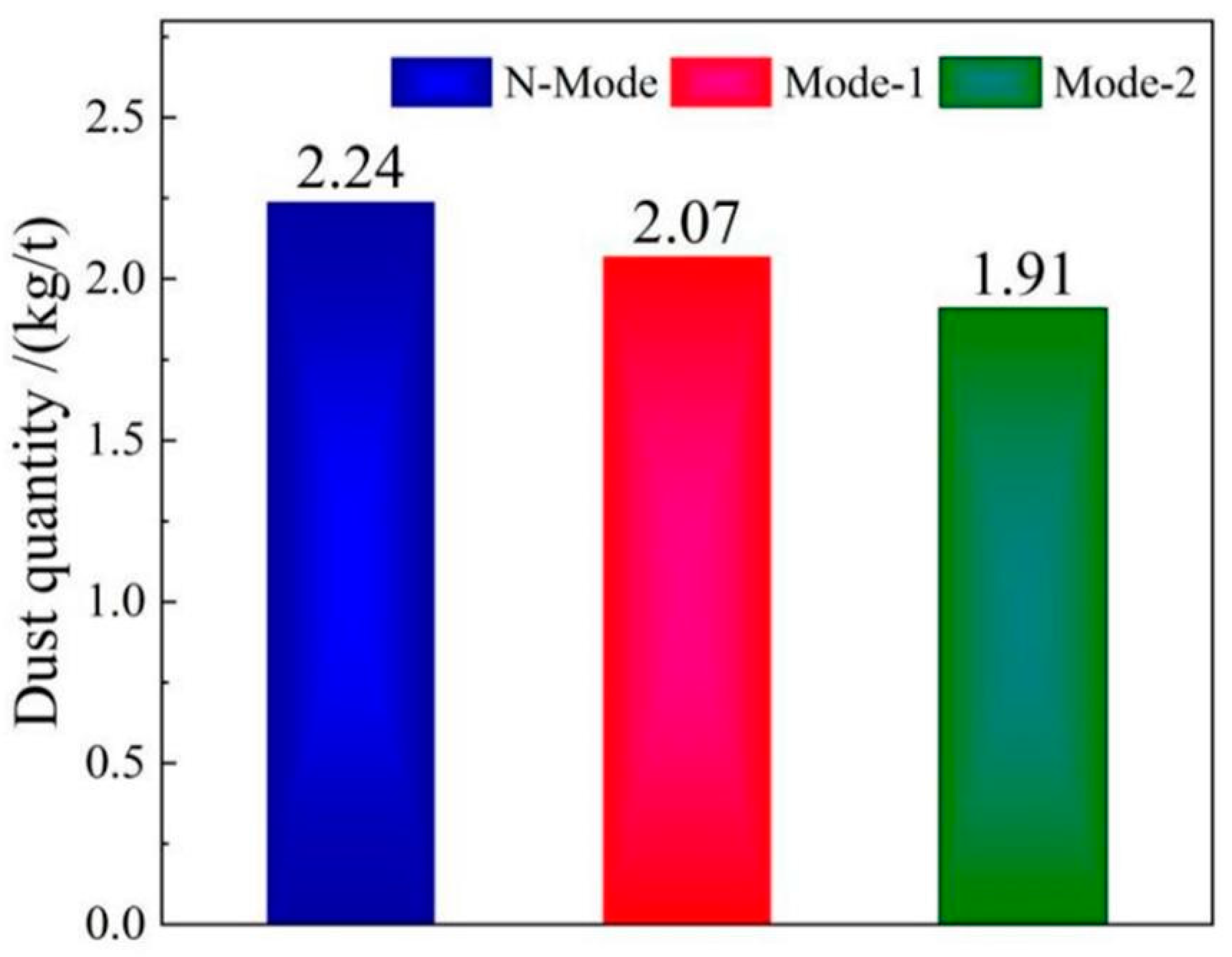
Figure 15 shows the amount of dust produced by large particles under different mode conditions in the industrial test process. The results show that the production of large particle size dust per ton of steel in N-Mode, Mode-1, and Mode-2 is 2.24 kg/t, 2.07 kg/t, and 1.91 kg/t, respectively. Compared with Mode-2 and N-Mode, the production of 0.17 kg/t and 0.33 kg/t is reduced by 7.6% and 14.7%, respectively. Figure 15 shows that the main reason is that the top blowing mixture of CO2 and O2 absorbs heat by the reaction between CO2 and C in the molten pool, which reduces the temperature of the fire zone and reduces the total amount of dust in steelmaking.

5. Conclusion

We studied the influence of COMI-B technology on converter smelting effect, analyzed the high temperature characteristics of CO2 participating in converter smelting reaction, and established the principle of CO2 on molten steel composition, energy recovery and pollutant reduction. Through laboratory research and industrial test results, that the utilization of CO2 in converter smelting was verified, and the beneficial effects of COMI-B compared with N-mode can be summarized as follows:
  • The COMI-B technology helps to improve the converter dephosphorization efficiency, the bubble proliferation effect, and cooling characteristics of top and bottom combined blowing CO2, and the dephosphorization rate is increased by 4.2%.
  • COMI-B technology helps to reduce the oxidizability of slag, oxidizability and N content of molten steel. The bubble proliferation effect of bottom blowing CO2 increases the rate of deoxidation and denitrification and reduces the carbon-oxygen product and nitrogen content of slag (FeO), molten steel and nitrogen by 2.04%, 1.37 × 10⁻⁴ and 20%, respectively.
  • The COMI-B technology helps to increase gas recovery and gas calorific value, top and bottom combined blowing CO2 participates in the reaction to generate a large amount of CO gas, and 1 mol CO2 produces 2 mol CO, which increases the recovery amount of gas with the same calorific value by 5.9%.
  • The COMI-B technology helps to reduce the soot production in the smelting process, the top blowing CO2 reduces the high temperature fire zone of the molten pool, reduces the amount of soot formed by the evaporation of molten iron, and reduces the large size soot content by 14.7%.
Based on many beneficial results obtained by CO2 in converter smelting process, CO2 can be used to produce a steel grade with high requirements for phosphorus and nitrogen content. CO2 can help to improve the cleanliness and purification of molten steel, provide favorable conditions for the stable production of subsequent refining and continuous casting processes, and realize the resource utilization of CO2. Only CO2 tons of steel in converter process can be used more than 5 kg. The CO2 utilization potential of COMI-B technology applied in iron and steel industry is more than 7.5 million tons of CO2. The research content of this paper can provide a reference for the application of CO2 in converter smelting.

Funding

This work was supported by the National Natural Science Foundation of China (NO.52004023 and NO.51734003)

Glossary

COMI-B Carbon dioxide oxygen mixed injection - bottom blowing
CCS Carbon capture and storage
CCU Carbon dioxide oxygen mixed injection - bottom blowing
CCUS Carbon Capture, Utilization and Storage
ES Early smelting stage
MS Middle smelting stage
LS Late smelting stage

References

  1. Duan, Y.; Han, Z.L.; Zhang, H.; Wang, H.Y. Research on the applicability and impact of CO2 emission reduction policies on China’s steel industry. International Journal of Climate Change Strategies and Management 2021, 13, 352–374. [Google Scholar] [CrossRef]
  2. Ren, L.; Zhou, S.; Peng, T.D. ; OXM A review of CO2 emissions reduction technologies and low-carbon development in the iron and steel industry focusing on China. Renewable and Sustainable Energy Reviews 2021, 143, 1–23. [Google Scholar] [CrossRef]
  3. Quader, M.A.; Ahmed, S.; Dawal, S.Z.; Nukman, Y. Present needs, recent progress and future trends of energy-efficient Ultra-Low Carbon Dioxide (CO2) Steelmaking (ULCOS) program. Renewable & Sustainable Energy Reviews. 2016, 55, 537–549. [Google Scholar]
  4. Chen, Y.; Zeng, J.H.; Zhang, M.; Pan, H. Research on key technologies of 38CrMoAl steel produced by BOF-LF-RH-CC processp. Advanced Materials Research 2011, 284-286, 1031–1038. [Google Scholar] [CrossRef]
  5. Zhao, P.; Dong, P.L. Carbon emission cannot be ignored in future of Chinese steel industry. Iron and Steel. 2018, 53, 1–7. [Google Scholar]
  6. Meylan, F.D.; Moreau, V.; Erkman, S. CO2 utilization in the perspective of industrial ecology, an overview. Journal of CO2 Utilization. 2015, 12, 101–108. [Google Scholar] [CrossRef]
  7. Shangguan, F.Q.; Li, X.P.; Zhang, C.X. Main energy-saving measures in steel production and the potential analysis of CO2 emission reduction. Energy for Metallurgical Ndusiry. 2009, 28, 3–7. [Google Scholar]
  8. Prokhorov, E.S. Analysis of equilibrium states of reacting carbon-oxygen thermodynamic system. Journal of Physics: Conference Series 2018, 1105, 1–7. [Google Scholar] [CrossRef]
  9. Sun, Y.J.; Zhou, L.F.; Li, Y. Development status of CO2 marine storage. Geological Science and Technology Information. 2018, 37, 218–224. [Google Scholar]
  10. Burton, E.A.; Birkinshaw, K.; Myer, L.; Myhre, R.; Coombs, M.J. Informing policy development for geologic carbon sequestration in California. Energy Procedia. 2009, 1, 4617–4624. [Google Scholar] [CrossRef]
  11. Nocitoa, F.; Dibenedetto, A. Atmospheric CO2 mitigation technologies: carbon capture utilization and storage (CCUS). Current Opinion in Green and Sustainable Chemistry. 2019, 1, 1–14. [Google Scholar] [CrossRef]
  12. Yang, G.D.; Li, Y.L.; Atrens, A.; Liu, D.Q.; Wang, Y.S.; Jia, L.; et al. Reactive transport modeling of long-term CO2 sequestration mechanisms at the Shenhua CCS demonstration project, China. Journal of Earth Science. 2017, 28, 457–472. [Google Scholar] [CrossRef]
  13. Peters, M.; Kçhler, B.; Kuckshinrichs, W.; Leitner, W.; Markewitz, P.; Müller, T.E. Chemical technologies for exploiting and recycling carbon dioxide into the value chain. Chem Sus Chem. 2011, 4, 1216–1240. [Google Scholar] [CrossRef]
  14. Voorhees, V.; Robert, F. Crediting carbon dioxide storage associated with enhanced oil recovery. Energy Procedia. 2017, 114, 7659–7666. [Google Scholar] [CrossRef]
  15. Aresta, M.; Dibenedetto, A.; Angelini, A. The changing paradigm in CO2 utilization. Journal of CO2 Utilization 2013, 3-4, 65–73. [Google Scholar] [CrossRef]
  16. Stuardi, F.M.; MacPherson, F.; Leclaire, J. Integrated CO2 capture and utilization: A priority. Current Opinion in Green and Sustainable Chemistry. 2019, 16, 71–76. [Google Scholar] [CrossRef]
  17. Vishal, V.; Chandra, D.; Singh, U.; Verma, Y. Understanding initial opportunities and key challenges for CCUS deployment in India at scale. 2021, 175, 1–19.
  18. Jiang, K.; Peta, A. "The development of Carbon Capture Utilization and Storage (CCUS) research in China: A bibliometric perspective. ". Renewable and Sustainable Energy Reviews 2021, 138, 110521. [Google Scholar] [CrossRef]
  19. Jiang, K.; Ashworth, P.; Zhang, S.; Liang, X.; Sun, Y.; Angus, D. China's carbon capture, utilization and storage (CCUS) policy: A critical review. Renewable and Sustainable Energy Reviews 2020. [CrossRef]
  20. Hao, T.; Zhang, S.; Chen, W.Y. "Assessing representative CCUS layouts for China’s power sector toward carbon neutrality. ". Environmental Science & Technology 2021, 16, 11225–11235. [Google Scholar]
  21. Steeneveldt, R.; Berger, B.; Torp, T.A. CO2 capture and storage closing the knowing-doing gap capture and storage closing the knowing–doing gap. Chemical Engineering Research and Design 2006, 84, 739–763. [Google Scholar] [CrossRef]
  22. Ravento’s, M.; Duarte, S.; Alarco’n, R. Application and Possibilities of Supercritical CO2 Extraction in Food Processing Industry: An Overview. Food Science and Technology International 2002, 8, 269–284. [Google Scholar] [CrossRef]
  23. Xu, Z.C.; Chen, X.Z.; Liu, J.G.; Zhang, Y.; Chau, S.; Bhattarai, N.; Wang, Y.; Li, Y.J.; Connor, T.; Li, Y.K. Impacts of irrigated agriculture on food–energy–water–CO2 nexus across metacoupled systems. Nature Communications 2020, 11, 1–12. [Google Scholar] [CrossRef] [PubMed]
  24. Park, C.; Hsieh, T.L.; Pottimurthy, Y.; Shah, V.; Xu, D.K.; Chen, Y.Y.; Fan, L.S.; Tong, A. "Design and operations of a 15 kWth subpilot unit for the methane-to-syngas chemical looping process with CO2 utilization. ". Industrial & Engineering Chemistry Research 2019, 59, 6886–6899. [Google Scholar]
  25. Kim, Y.; Hyun, K.; Ahn, D.; Kim, R.; Park, M.H.; Kim, Y. "Efficient aluminum catalysts for the chemical conversion of CO2 into cyclic carbonates at room temperature and atmospheric CO2 pressure. ". Chem Sus Chem 2019, 12, 4211–4220. [Google Scholar] [CrossRef] [PubMed]
  26. Singh, V.; Buelens, L.C.; Poelman, H.; Saeys, M.; Marin, G.B. ; GalvitaVV. "Upcycling the carbon emissions from the steel industry into chemicals using three metal oxide loops.". Energy Advances 2022, 1, 367–384. [Google Scholar]
  27. Valderramaa, M.; Puttenb, R.; Gruter, G. The potential of oxalic-and glycolic acid based polyesters (review). Towards CO2 as a feedstock (Carbon Capture and Utilization-CCU). European Polymer Journal. 2019, 119, 445–468. [Google Scholar]
  28. Zhang, J.J.; Qian, Q.L.; Wang, Y.; Bediako, B.B.; Yan, J.; Han, B.X. Synthesis of ethanol from aryl methyl ether/lignin, CO2 and H2. Chemical Science. 2019, 10, 10640–10646. [Google Scholar] [CrossRef] [PubMed]
  29. Chang, W.T.; Lee, M.S.; Den, W. Simultaneous carbon capture, biomass production, and diary wastewater purification by spirulina maxima photobioreaction. Industrial & Engineering Chemistry Research. 2013, 52, 2046–2055. [Google Scholar]
  30. Figueroa, J.D.; Fout, T.; Plasynski, S.; McIlvried, H.; Srivastava, R.D. Advances in CO2 capture technology-the U. S. department of energy's carbon sequestration program. International Journal of Greenhouse Gas Control. 2008, 2, 9–20. [Google Scholar] [CrossRef]
  31. Bu, X.P. CO2 capture technologies and application. Clean Coal Technology. 2014, 20, 9–13. [Google Scholar]
  32. Klemeš, J.; Bulatov, I.; Cockerill, T. Techno-economic modelling and cost functions of CO2 capture processes. Computers & Chemical Engineering 2007, 31, 45–455. [Google Scholar]
  33. Wei, G.S.; Zhu, R.; Wu, X.T.; Dong, K.; Yang, L.Z.; Liu, R.Z. Technological innovations of carbon dioxide injection in EAF-LF steelmaking. Jom. 2018, 70, 969–976. [Google Scholar] [CrossRef]
  34. Lv, M.; Zhu, R.; Wei, X.Y.; Wang, H.; Bi, X.R. Research on top and bottom mixed blowing CO2 in converter steelmaking process. Steel Research International. 2012, 83, 11–15. [Google Scholar] [CrossRef]
  35. Gu, Y.L.; Wang, H.J.; Zhu, R.; Wang, J.; Lv, M.; Wang, H. Study on experiment and mechanism of bottom blowing CO2 during the LF refining process. Steel Research International. 2014, 85, 589–598. [Google Scholar] [CrossRef]
  36. Wei, G.S.; Zhu, R.; Tang, T.P.; Dong, K.; Wu, X.T. Study on the impact characteristics of submerged CO2 and O2 mixed injection (S-COMI) in EAF steelmaking. Metallurgical & Materials Transactions B 2019, 50B, 1077–1090. [Google Scholar]
  37. Wei, G.S.; Zhu, R.; Wu, X.T.; Yang, L.Z.; Dong, K.; Cheng, T.; et al. Study on the fluid flow characteristics of coherent jets with CO2 and O2 mixed injection in electric arc furnace steelmaking processes. Metallurgical & Materials Transactions B 2018, 49B, 1405–1420. [Google Scholar]
  38. Wei, G.S.; Zhu, R.; Cheng, T.; Dong, K.; Yang, L.Z.; Tang, T.P.; et al. Effect of main gas composition on flow field characteristics of supersonic coherent Jets with CO2 and O2 mixed injection (COMI) at steelmaking temperature. ISIJ International. 2018, 58, 842–851. [Google Scholar] [CrossRef]
  39. Wu, W.; Yang, Q.X.; Gao, Q.; Zeng, J.Q. Effects of calcium ferrite slag on dephosphorization of hot metal during pretreatment in the BOF converter. Journal of Materials Research and Technology 2020, 1–8. [Google Scholar] [CrossRef]
  40. Assis, A.N.; Tayeb, M.A.; Sridhar, S.M.; Fruehan, R.J. Phosphorus equilibrium between liquid iron and CaO-SiO2-MgO-Al2O3-FeO-P2O5 slags: EAF slags, the effect of alumina and new correlation. Metals. 2019, 9, 1–12. [Google Scholar] [CrossRef]
  41. Lv, M.; Zhu, R.; Yang, L.Z. High efficiency dephosphorization by mixed injection during steelmaking process. Steel Research International, 2019; 1–7. [Google Scholar]
  42. Xue, Y.K.; Zhao, D.G.; Wang, S.H.; Li, C.X.; Guo, R.H. Phosphorus vaporization behaviour from converter slag. Ironmaking & Steelmaking. 2019, 48, 1–8. [Google Scholar]
  43. Wu, H.J.; Li, Q.Q.; Wang, Z.; Jiang, F.J. Vacuum denitrification and nitrogen absorption of molten steel under ultra-low nitrogen conditions. Materials Science & Technology. 2019, 35, 240–246. [Google Scholar]
  44. Diao, W.C.; Zhang, M.; Xu, T. Study on nitrogen control process during converter steelmaking process. Science & Technology of Baotou Steel. 2017, 43, 20–22. [Google Scholar]
  45. Fruehan, R.J. Fundamentals and practice for producing low nitrogen steels. ISIJ International. 1996, 36, 58–S61. [Google Scholar] [CrossRef]
  46. Zhou, J.; Qin, Z.; Zhang, B.; Peng, Q.C.; Qiu, S.T.; Gan, Y. Behaviors of denitrogenation in RH-MFB. Journal of Iron & Steel Research International. 2013, 20, 40–44. [Google Scholar]
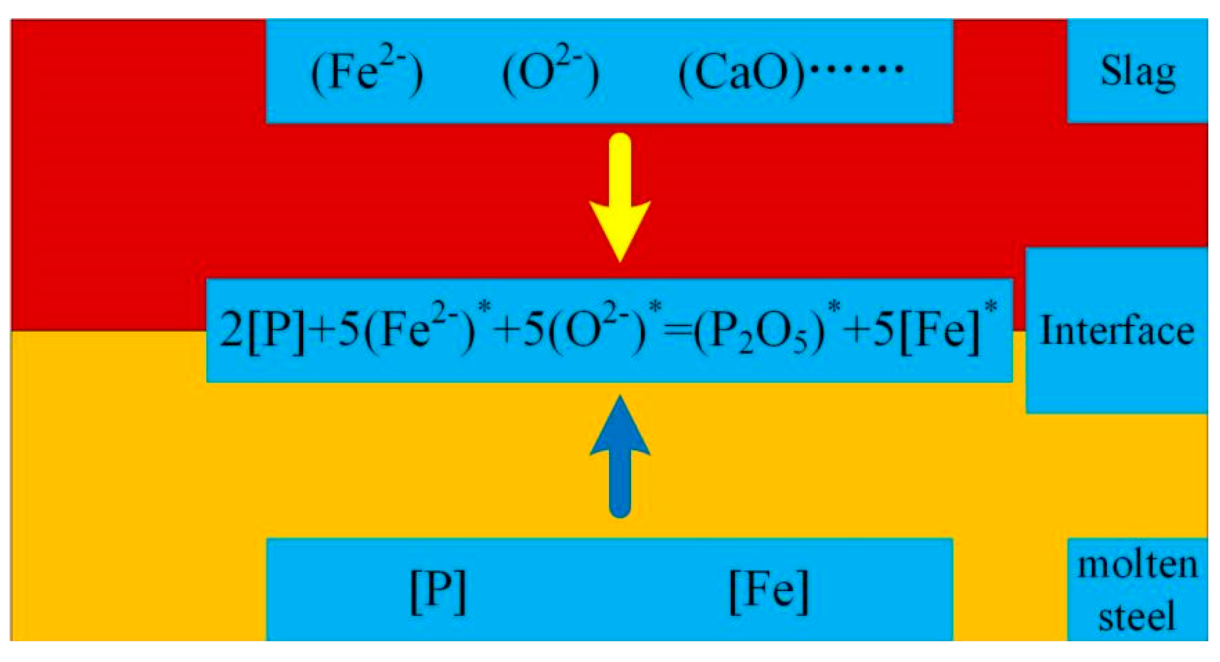
Figure 1. Dephosphorization reaction at slag steel interface.
Preprints 68301 g001
Figure 2. Terminal nitrogen content change of molten steel.
Preprints 68301 g002
Figure 3. Formation mechanism of smoke and dust.
Preprints 68301 g003
Figure 4. Process flow of CO2 utilization.
Preprints 68301 g004
Figure 5. Experimental study on dephosphorization by CO2-O2 mixed blowing.
Preprints 68301 g005
Figure 6. Dephosphorization effect of end point molten steel.
Preprints 68301 g006
Figure 7. Laboratory CO2 injection decarburization study.
Preprints 68301 g007
Figure 8. Comparison of slag (FeO).
Preprints 68301 g008
Figure 9. Carbon and oxygen product of end point molten steel.
Preprints 68301 g009
Figure 10. Denitrification kinetics of molten steel under bottom blowing of Ar/ CO2 / O2.
Preprints 68301 g010
Figure 11. Change of nitrogen content in molten steel at the end point.
Preprints 68301 g011
Figure 12. The volume and composition of furnace gas change with the proportion of CO2 injection.
Preprints 68301 g012
Figure 13. Comparison of converter gas volume.
Preprints 68301 g013
Figure 14. Experimental study on dust amount.
Preprints 68301 g014
Figure 15. Comparison of dust removal ash.
Preprints 68301 g015
Table 1. Thermodynamic data of CO2 participating in the reaction.
Element Reaction ΔGθ/(J/mol) ΔGθ1573K/
(kJ/mol)
ΔGθ1873K/
(kJ/mol)
C O2 + [C]=CO2(g) -419050+42.34T -352.45 -339.75
O2 + 2 [C]=2CO(g) -281160-84.18T -413.58 -438.83
CO2(g) + [C]=2CO(g) 137890-126.52T -61.13 -99.08
Fe O2(g) +2Fe(l)=2(FeO) -458980+87.62T -321.15 -294.87
CO2(g) + Fe(l)=(FeO)+CO(g) 48980-40.62T -14.92 -27.10
Si O2 + [Si]=(SiO2 -804880+210.04T -474.49 -411.48
CO2(g) + 1/2 [Si]=1/2(SiO2)+CO(g) -123970+20.59T -91.58 -85.40
Mn O2 + 2 [Mn]=2(MnO) -824460+253.88T -425.11 -348.94
CO2(g) + [Mn]=(MnO)+CO(g) -133760+42.51T -66.89 -54.14
P O2+4/5 [P]+8/5(CaO)=
2/5(4CaO·P2O5)
-845832+255.3T -444.25 -367.66
CO2(g)+2/5 [P]=1/5(P2O5)+CO(g) 13245+19.753T 44.32 50.24
CO2(g)+2/5 [P]+4/5(CaO)=
1/5(4CaO·P2O5)+CO(g)
-144446+43.22T -76.46 -63.49
Table 2. Main chemical composition of hot metal and scrap.
Category C/(%) Si/(%) Mn/(%) P/(%) S/(%)
Molten iron 3.80~4.78 0.36~0.85 0.34~0.79 0.085~0.151 0.025~0.132
Average value 4.51 0.58 0.55 0.125 0.054
Steel scrap 0.14~0.25 0.18~0.62 0.35~1.50 0.013~0.048 0.018~0.052
Average value 0.21 0.33 0.76 0.026 0.031
Pig iron 4.08~4.85 0.47~1.14 0.41~0.85 0.101~0.178 0.052 ~0.152
Average value 4.28 0.62 0.64 0.146 0.062
Table 3. Slagging agent and coolant addition.
Lime/
(kg/t)
Light burned dolomite/(kg/t) Limestone /(kg/t) Raw dolomite/(kg/t) Mineral/
(kg/t)
Sludge ball/(kg/t)
21.8 18.0 10.9 3.8 10.7 10.6
Table 4. Smelting stage.
ES/(min) MS/(min) LS/(min)
<4.5 4.5≤t ≤10.5 >10.5
Disclaimer/Publisher’s Note: The statements, opinions and data contained in all publications are solely those of the individual author(s) and contributor(s) and not of MDPI and/or the editor(s). MDPI and/or the editor(s) disclaim responsibility for any injury to people or property resulting from any ideas, methods, instructions or products referred to in the content.
Copyright: This open access article is published under a Creative Commons CC BY 4.0 license, which permit the free download, distribution, and reuse, provided that the author and preprint are cited in any reuse.
Prerpints.org logo

Preprints.org is a free preprint server supported by MDPI in Basel, Switzerland.

Subscribe

© 2024 MDPI (Basel, Switzerland) unless otherwise stated