1. Introduction
1.1. Background
With heavy lifting and manual material handling (MMH), lower back pain (LBP) is a major factor contributing to work-related musculoskeletal disorders (WMSD). Intense compression pressure on the spine from heavy lifting can cause degeneration, fractures, or chronic damage to the lumbar spine [
1]. By using off-body mechanical devices such as forklifts and trolleys to transport heavy loads, workers may reduce the risk of musculoskeletal injuries during MMH. Although lifting aids can alleviate the burden of heavy loads on laborers [
2], they are often not used if the loads are within human capacity [
3]. To address this issue, exoskeleton technology is being hailed as a promising new approach to support the human body and reduce the risk of musculoskeletal injuries. This technology involves wearing a device designed to support and protect workers’ health [
4]. An exoskeleton with active actuators can also enhance human strength for load-handling tasks.
In traditional robotic systems, especially those used in industrial applications, stiff actuators are employed for high position precision, stability, and high torque bandwidth. However, for physical human-robot interaction (pHRI), such as in rehabilitation, assistive, and service robotics, the actuators must prioritize safety and comfort for human operators. As a result, these types of robotic systems often use compliant actuators to increase adaptability and safety. When the external load changes, the compliant actuator allows for deviation from the preset position. Rigid actuators, on the other hand, maintain their position regardless of external force. Compliance in the actuation system can increase adaptability and safety [
5].
To address the drawbacks of rigid actuators and ensure safe human-robot interaction, series elastic actuators (SEAs) have been introduced in robotics and widely used. In an SEA, there is an elastic element connected to the mechanical energy source [
6]. This architecture allows for improved force (or torque) control and reduces the influence of inertia and friction [
7]. By using SEAs with closed-loop controls and active force sensors, the impact of inertia and friction is reduced. Hooke’s Law can be used to calculate the force on the output load based on the deflection of the compliant part. A feedback force controller adjusts the motor’s current to compensate for any discrepancies between actual and intended forces [
8]. SEAs can also reduce the cost of robotic systems by using electrical current in the joints to estimate forces and movements instead of expensive sensors [
9].
SEAs have proven to be successful in several robotic applications, including wearable robots, such as bipedal, quadruple, and dual-arm robots [
10]. Because SEAs are naturally compliant for safe human-robot interaction, they are well-suited for assistive exoskeleton applications. Two studies in the literature have used SEAs for lumbar support exoskeletons at the hip joints [
11,
12]. One exoskeleton uses four SEA units with clutches to assist with hip abduction and adduction, as well as hip flexion and extension [
11]. The other exoskeleton uses a SEA-based wire-driven mechanism that reduces muscle activity by 33.0% and 41.6% in semi-squatting postures [
12]. However, wearable robots would be more effective if they were more compact and lightweight than current SEA designs, which are bulky and heavy. To address this, a novel energy storage-rotary series elastic actuator (ES-RSEA) has been developed in our previous publication [
13,
14] to assist with squat lifting tasks. The compact and modular design of the ES-RSEA leverages the biomechanics of the human squat strategy to utilize the kinetic energy of limbs for semi-squat lifting tasks.
The main challenge for SEA technology is the dependence of SEA performance on spring stiffness. A balance must be struck between compliance and torque transmission. High force control and compliance come from low-stiffness springs, while high torque transmission efficiency is achieved with high-stiffness springs, but at the cost of reduced compliance and control. High torque estimation accuracy requires high deflection linearity with torque relation. Choosing the right spring stiffness based on application biomechanics ensures high compliance and maximum force. Designing a torsional spring that is low in stiffness while robust in torque is challenging, especially in wearable robotics where weight and dimensions need to be minimized.
1.2. Torsional Springs for a Rotary Series Elastic Actuator: State of the Art
The design of torsional springs in Series Elastic Actuators (SEAs) plays a crucial role in determining the overall performance of the system. As the deflection of a torsional spring in an SEA can be used to measure the applied torque, it can also be considered a type of force sensor. The torsional spring in an SEA acts as the interface between the actuator and the load, transmitting torque while also measuring the force being applied. The design of the torsional spring must therefore be carefully considered to ensure accurate torque measurement and efficient force transmission.
In SEA development, much effort has been devoted to creating unique modules customized for particular applications. Since the purposes of SEA are so diverse, there are currently no standard solutions for elastic components, and various designs of elastic components have been implemented with different specifications. Torsional springs incorporated into the transmission drive or custom torsional springs attached directly to the load are often used in compliant systems [
7]. The single element elasticities are best suited to developing a lightweight and portable method that meets the spring needs of a single application;
Table 1 shows the main specifications for the current designs of torsional spring.
In the literature, two different types of custom-designed torsional springs have been used. The spring blades are positioned equally along the output shaft and bent sinuously. Because of this design, the SEA's space waste is dramatically decreased, and the deflection angle is significantly enhanced. In contrast to the first form of changing the spring leaf into a personalized pattern, the second type is the spiral spring design, which is regarded as a standard shape based on the traditional mathematical design of the Archimedes spiral.
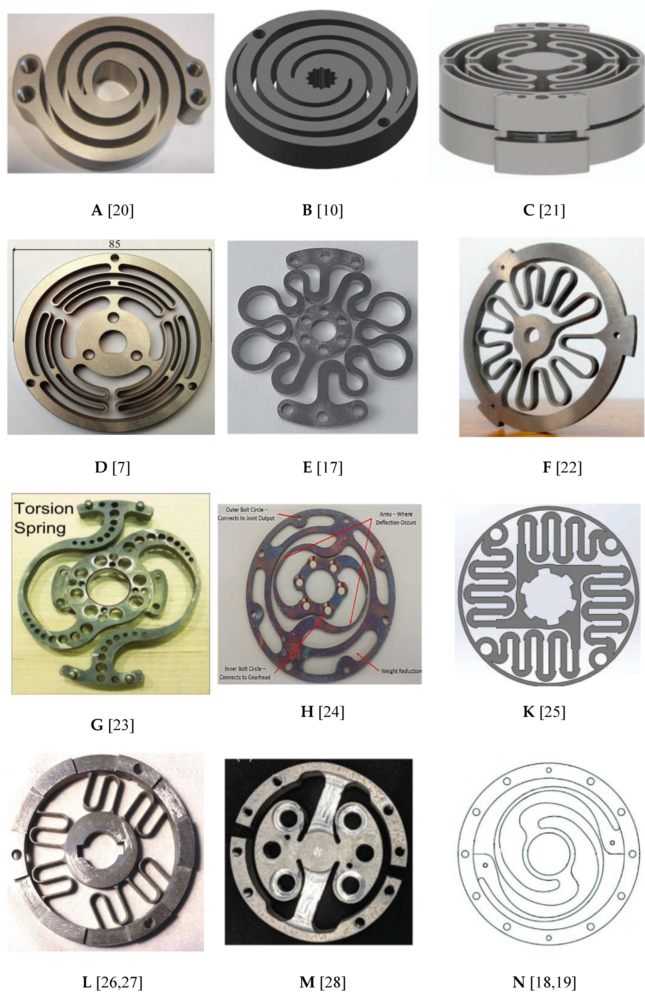
The springs shown in
Figure 1 (A, B, C, D, E, F, G, H, K, L, and M) are designed based on finite element analysis (FEA).
Figure 1 (A) [
15] shows a custom-made spiral spring that was built based on earlier study work in
Figure 1 (B) [
10]. As torque strains the spring, the double spiral design suspends undesirable radial forces working on the center of the spring. The spring was created using fundamental beam bending equations and ANSYS Workbench FEA simulation data. Another type of spiral-shaped torsion spring is a custom spiral-shaped torsion spring [
16]. This spiral spring is made from a steel strip and fitted with the Kurmet biped robot, whereas the other varieties of spiral springs are made from a steel plate using electrical discharge processing. In these earlier studies, a spring design configuration was chosen based on the application requirements and then modelled in an FEA methodology. The FEA study is iterated and improved with incremental design parameter changes until a solution is developed that meets performance standards while remaining within packaging constraints. However, other researchers used double planner torsional springs in a series connection to suit their application requirements, as shown in
Figure 1 (D).
Figure 1 (C) shows how it changed to a new design. Moreover, as illustrated in
Figure 1 (E), work [
17] develops a compact torsion spring for a series elastic actuator for an active orthosis. The spring's form was determined using FEM-based geometry optimization to reduce the maximum equivalent stress.
All the initial designs have been developed and used in various exoskeleton or orthosis applications. The torsional spring was designed for clutchable SEA, which is used for lifting tasks in the hip exoskeleton and has a peak torque of 60 Nm and a spring stiffness of 800 Nm/rad [
11]. This spring has a disc-shaped construction to reduce the size and weight of the torsion spring. This spring's additional design features were unavailable. Then, with alternative spring designs, the clutchable SEA for hip exoskeleton was created again for assistive gait [
18,
19].
Figure 1 demonstrates that the disc-shaped spring can transfer a maximum torque of 70 Nm with a 400 Nm/rad stiffness (N). The essential features of the spring's components A-L are summarized in
Table 1. Elements G, H, M, and, N on the other hand, did not have any data available.
In general, it can be challenging to find a torsional spring component that satisfies the requirements for low stiffness, compactness, and lightweight design while still capable of handling high peak torques. The existing designs are mostly based on researcher perspectives rather than optimized for performance. There is a lack of standard design methodology for torsional springs, making the development of a novel topological torsion spring that meets the specific design requirements of Energy Storage-Rotary Series Elastic Actuator (ES-RSEA) for lifting task exoskeleton applications highly desirable. This torsion spring design needs to be lightweight, compact, and able to withstand high torques while maintaining low inherent stiffness. Existing torsional springs in the market often lack these features, making the investigation of a new design imperative for the success of the ES-RSEA or any other SEA for lifting task applications.
1.2. Design Objectives of the Proposed Torsional Spring
This article aims to design a compact, lightweight, and cost-effective torsional spring with excellent torsion-compliant properties to be used in the Energy Storage-Rotary Series Elastic Actuator (ES-RSEA) of a lumbar support exoskeleton. The torsional spring must handle high assistive torques while ensuring compliance to support the human operator during lifting tasks and meet the low weight and size requirements of the actuator. The design methodology considers factors such as design for manufacturability (DFM), material selection, and cost-effectiveness. A low-cost material, such as AISI 4140 alloy steel, has been selected for its yield strength up to 1400 MPa after heat treatment and a safety factor of 1.65. This material selection balances cost-effectiveness with performance requirements.
2. Design Considerations
2.1. Design For Manufacturing (DFM) Approach
In the design of the torsion spring, Design for Manufacturing (DFM) principles were employed to ensure compatibility with the ES-RSEA actuator. DFM is a design approach that aims to simplify, optimize, and refine product designs for ease of manufacturing and to achieve a better final product at a lower cost. The optimization process in DFM offers several optimal solutions for the manufacturing process and selects the best solution among them [
29,
30]. DFM takes into consideration the manufacturing difficulties in the product development stage, which leads to a reduction in overall manufacturing cost and improved product reliability, quality, and reduced complexity without sacrificing standards [
31].
The DFM approach used for the torsion spring in this study was based on two principles: ease of manufacture and assembly, and consistency with the manufacturing capability to meet the product's criteria [
32]. The goal was to manufacture the torsion spring using existing technologies available at the research institute or in the local market. The DFM guidelines identified design features that are challenging to manufacture using machining processes and thus need to be avoided, such as insufficient or inaccurate designs, excessive number of holes with widely divergent diameters, nonstandard hole diameters, tight tolerances, and sharp corners [
33].
The manufacturing method for the spring was chosen based on several criteria, including manufacturing cost, machine availability, and cutting quality. The machining process for the torsion spring was carried out using a water jet cutting machine, which offers efficient, safe, and highly accurate cutting [
34]. The limitations of the water jet machine were considered in the design process, such as the minimum permissible thickness of the flexible spring segment (set at 2 mm) and the width of the material plate (set at 8 mm). Additionally, the nozzle size of the waterjet cutting stream was considered when calculating the space for designing the flexible segment between two rings. The outside ring was designed with the highest permissible diameter of 85 mm to provide enough space for compliance design.
Material selection was an important part of the design process. Different materials such as maraging steels and titanium alloys have been used in the literature, but these high-cost materials were not considered in this work due to cost-effectiveness concerns. Chromium-molybdenum alloy steel AISI 4140 was chosen for its low cost, wide availability, and high fatigue and torsional strength with a yield strength of 1400 MPA after heat treatment at 315°C. Low-alloy steel material has good machinability, high ductility, and can be produced using traditional methods in the annealed state.
2.2. Mechanical Design Considerations
The ES-RSEA actuator was designed for use in a lumbar support exoskeleton to provide torque assistance during the ascent and descent phases of lifting tasks [
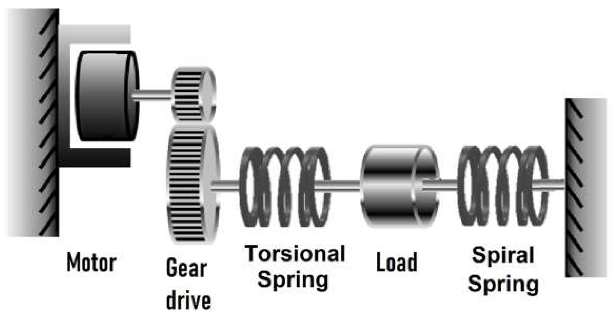
13]. The rotary series elastic actuator (RSEA) and the energy storage device (ES) work together to achieve this goal. The RSEA provides mechanical compliance and a high torque-weight ratio at the interface between the user and the exoskeleton, reducing the risk of injury and protecting both the human body and exoskeleton structure. The design and topology of the actuator affect the shape and properties of the torsional spring, which is the main component of the RSEA. The ES-RSEA configuration is shown in
Figure 2. The ES-RSEA has a nominal torque of 45.7 Nm and a spring stiffness of 450 Nm/rad, chosen for its optimal performance in terms of accuracy, bandwidth, compliance, and efficiency of torque transmission [
13]. Further details on the stiffness selection are discussed in the next section.
The ES-RSEA is designed to be lightweight and compact, using a planar torsional spring with a maximum weight of 150 g. The elastic element (torsional spring), located between the harmonic drive and load side, connects the external ring of the spring to the harmonic drive gear through a thin flange and the inner ring (20 mm diameter) directly to the load link [
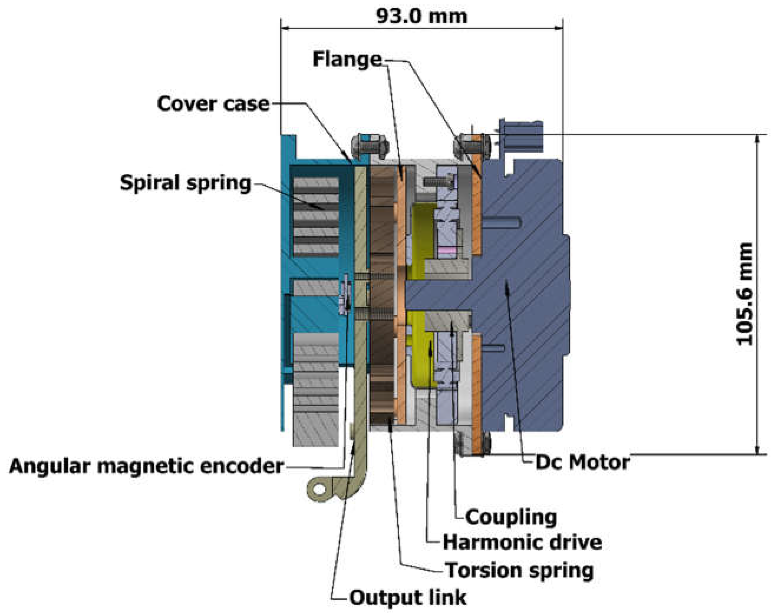
13]. The torsional spring can be designed using a simple model of two rings connected by a flexible segment for the desired compliance. The shape of the flexible segment can be optimized through the mass reduction factor and FEA design. The ES-RSEA actuator has a compact design, with an axial length of 93 mm.
Figure 3 illustrates the cross-section of the ES-RSEA actuator [
13]. According to the characteristics, topology, and cutting technology accuracy, the specific design parameters of the torsional spring are summarized in
Table 2.
2.3. Selection of Spring Stiffness
The spring stiffness selection plays a crucial role in the performance and characteristics of Series Elastic Actuators (SEAs). The accuracy of measuring an elastic element's displacement and applied torque in a SEA is dependent on the suitable spring stiffness [
7]. This is because the spring deflection is used to measure the applied torque, and a more compliant spring allows for less torque signal quantization, which improves torque accuracy [
7]. It is also important to have a high linearity in the relationship between the applied torque and angular displacement to provide accurate torque estimation and effective control performance [
7].
Furthermore, the output torque of the actuator relies on the deflection and spring stiffness. An overly stiff spring may cause discomfort to the human operator and result in inaccurate control of torque fidelity. Hence, the suitable spring stiffness must be chosen carefully as a trade-off between a large torque bandwidth and low compliance. The torque range accuracy and motor control performance should also be considered when designing the spring characteristics [
35].
The torque measurement resolution is influenced by the spring stiffness as the exerted torque is computed from the spring displacement [
7]. High deflection linearity with torque relation should be ensured to achieve great torque estimation accuracy and torque transmission performance [
36]. Selecting the proper spring stiffness for a given application will result in a more energy-efficient system [
35]. To sustain high compliance throughout the task cycle while maintaining the ability to deliver maximum force, it is necessary to choose the right SEA springs based on specific application biomechanics. Balancing controller bandwidth and high torque resolution is key in this process [
17].
The relationship between the torque resolution and maximum angular deflection of a torsional spring depends on its design features like stiffness, wire diameter and material properties. The maximum angular deflection represents the maximum twisting or rotation the spring can undergo before it reaches its limit, while torque resolution measures the smallest amount of torque that can produce a noticeable change in angular deflection. Typically, a torsional spring with a higher stiffness has a higher torque resolution but a lower maximum angular deflection, and vice versa. However, the relationship can vary based on the torsional spring's specific design, and the optimal design may require a trade-off between these two factors based on the application's specific requirements and constraints [
21,
22,
37].
The suitable spring stiffness value of series elastic actuators (SEAs) in recent studies has been found to range from 100 to 1600 Nm/rad based on literature research [
38,
39,
40]. Most SEAs use high-stiffness springs to provide high force transmission efficiency, which can compromise compliance, back drivability, and force control performance [
8]. Theoretical studies and simulations have shown the applicability of these values as a trade-off between the numerous design requirements of SEAs.
The appropriate value of the physical elasticity for the hip joint when designing a wearable robot for lifting activities is challenging to determine. This is because the assessment of the lower limb joints' viscoelastic characteristics has revealed varied findings for each examined joint in biomechanics research and wearable robotics literature [
7]. Currently, most SEAs developed for hip exoskeletons have a stiffness of approximately 800 Nm/rad [
41,
42,
43,
44,
45,
46,
47]. Therefore, the stiffness of 200–800 Nm/rad was selected as the design target for the lower limb exoskeleton for lifting tasks. The proposed ES-RSEA in this study aims to improve compliance in human-robot interaction by choosing a low stiffness value of approximately 450 Nm/rad, while still providing frequency bandwidth that satisfies the target application requirements. The designed torsion spring for the ES-RSEA has a stiffness of 450 Nm/rad, a bearing torque of 45.7 Nm, and the maximum angular deflection 5.8 degree.
3. Topology Design of Torsion Spring
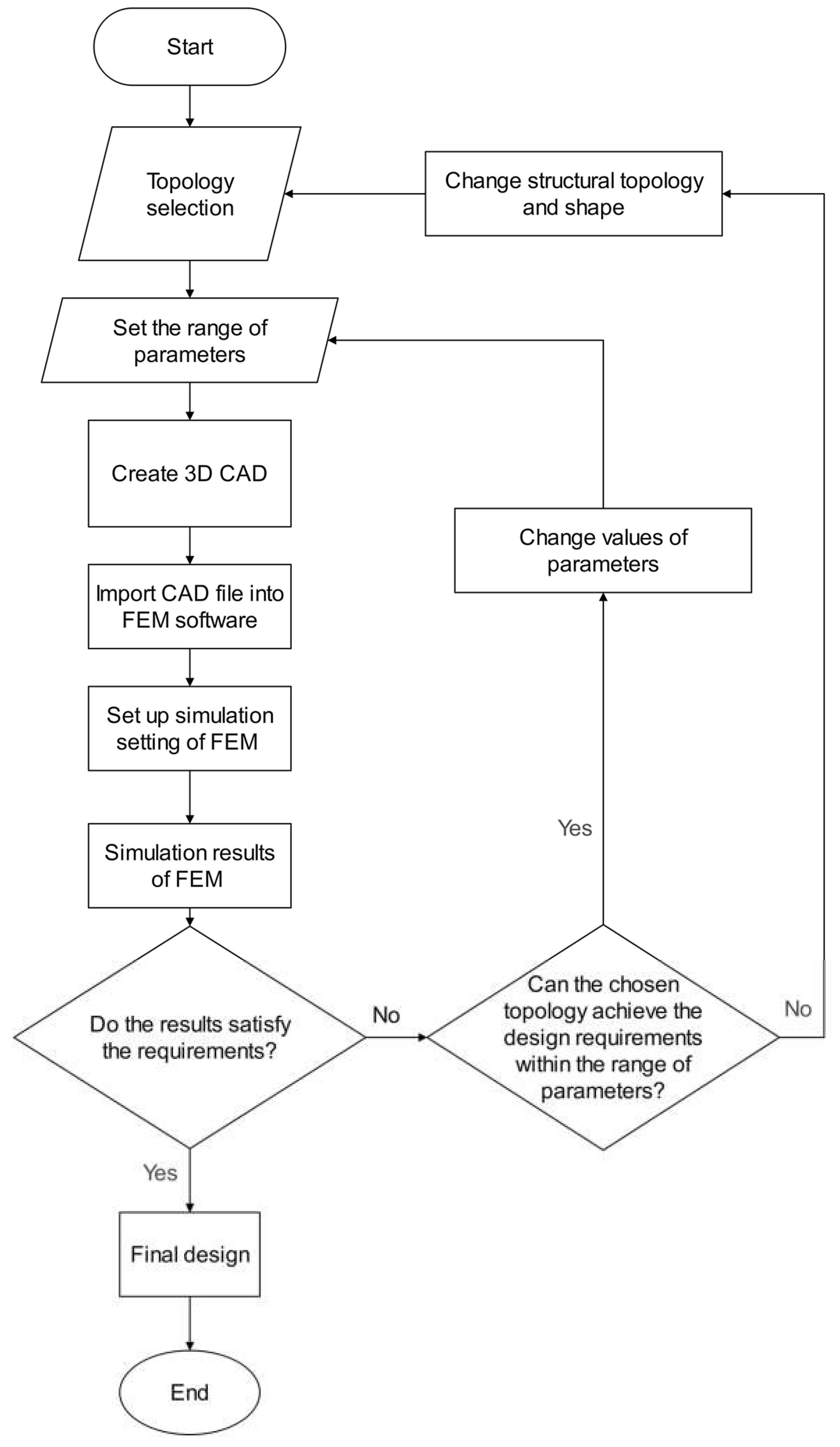
The design of the torsion spring involves two main stages. The first step is to determine the topologies with specific parameters that meet the design and DFM requirements. The second step is to optimize the spring design parameters based on the chosen topology using FEM-based geometry optimization to minimize the equivalent stress and achieve the desired spring stiffness while ensuring a lightweight design. The flowchart in
Figure 4 summarizes the design process of the torsion spring.
Initially, a set of topologies is selected, each defined by a set of parameters. A finite element analysis (FEA) program is then used to evaluate the design requirements of each topology. If the design requirements are not met, the following options are available:
The design optimization phase concludes when the design criteria are satisfied (i.e. the spring stiffness is approximately 450 Nm/rad) and the chosen topology is deemed a good design. This design methodology ensures that at least one feasible design is obtained that meets the design objectives outlined in
Table 2.
3.1. Selection of the Suitable Topology
The proposed torsion spring consists of two main parts: the inner coil and outer coil. The flexible element, located between the two coils, provides the desired compliance and stiffness of the spring and induces elastic deformation when the inner and outer coils rotate relative to each other. The flexible element also acts as a bridge to transfer torque between the coils and reducing impact. Its shape and geometry can be developed based on mass reduction and FEA-based optimization designs. The maximum exterior diameter of the outer ring and maximum interior diameter of the inner ring are 85 mm and 20 mm, respectively, as per the human hip joints and ES-RSEA structure.
A topology optimization was conducted to determine a compliant design for the flexible elements that meets the application requirements. It was concluded that it is preferable for the elastic element to have a longer force transmission path, as this leads to reduced equivalent stresses and the desired stiffness can be achieved with larger cross-sections.
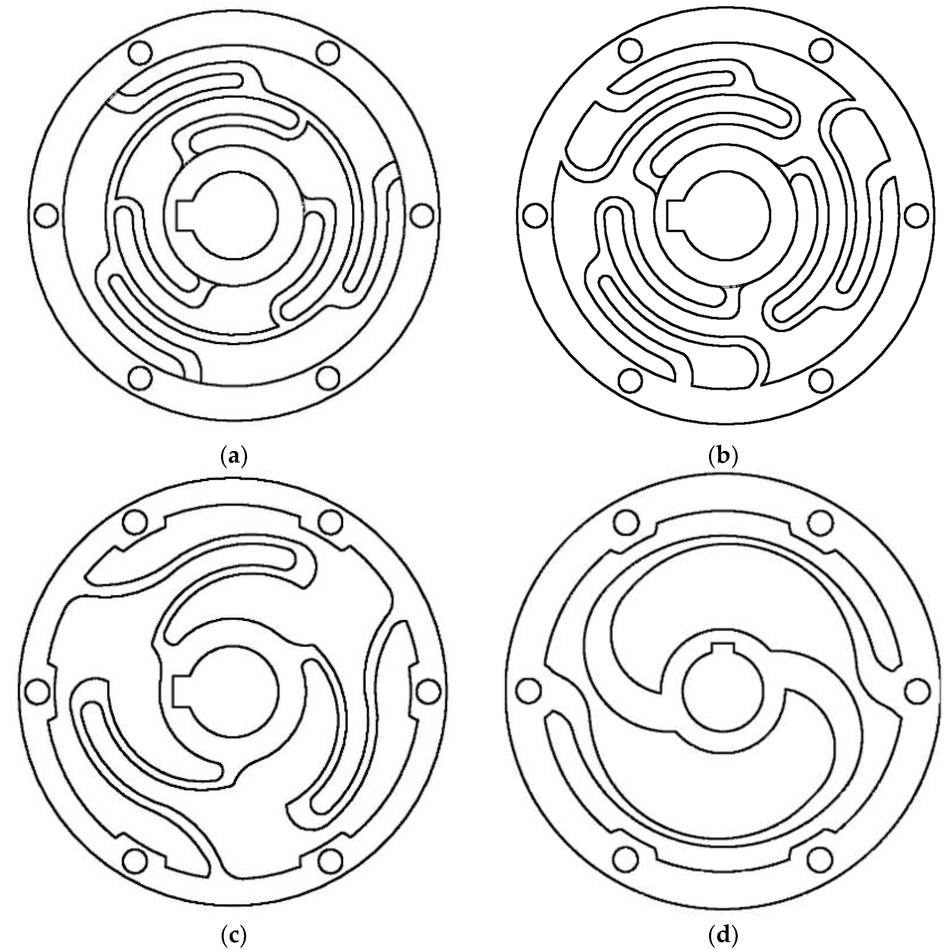
Four types of elastic elements with symmetric structural topologies were investigated and are shown in
Figure 5. Each element's topology was modified until reaching the optimum topology of Element D. The number and arrangement of the flexible components are important, but their dimensional characteristics determine how the elements are morphologically implemented. The first three topologies have symmetric structures with three elastic elements in radial replication, while the fourth topology has two symmetrical elastic elements. Elements A, B, C, and D were examined during the geometry identification process. The elastic element was modeled as follows:
Parameter range values for each topology were determined and applied.
The parts were modeled in Autodesk Inventor (2020) using parametric CAD.
The CAD file was imported into ANSYS Workbench (2022 R2, USA) for FEM-based geometry optimization.
Design requirements-based simulations were conducted to achieve the desired spring characteristics.
The stiffness and linearity of the element were tested using iterative FEM in ANSYS through static performance analysis, and the optimal structure was found through optimization and selection procedures. Topologies A, B, and C showed unpromising results for achieving the spring characteristics with design and DFM considerations. Element A was too rigid and could not provide the desired spring deflection, despite having the lowest equivalent stress among all the topologies. Element B had improved output deflection, but still did not reach the desired stiffness, and had higher equivalent stress than Element A. Both elements A and B were considered complicated and costly to manufacture due to their many arched lamellae, edges, and curves. Element C had a higher equivalent stress than Element A, but lower than Element B. Its deflection reached a higher level than both previous designs, but the maximum equivalent stress exceeded the maximum allowable stress for the chosen material at the root (stress concentration) due to its sharply arched lamellae. The deflection of this element almost achieved the desired stiffness, but it did not fulfill the DFM recommendations.
Elastic element thickness was reduced in certain areas due to adapting the geometry of element C to selected spring properties, resulting in disadvantages regarding the calculated equivalent stresses, accuracy of the shape, and complexity of the design. Therefore, element C failed to fulfill the DFM considerations to meet the required spring characteristics. This was also true for elements A and B.
The design of a flexible element needs to be compliant enough to achieve the desired spring deflection, but if the material is rigid and not highly ductile, it may result in high stress under the applied torque. Element D was designed with a sufficient torque transmission path length to reduce the generated stress and provide the capability to deform the element to achieve the desired spring stiffness and deflection. It has a smooth corrugation for the arched lamellae that reduces radial deformation and distributes the resulting stress evenly throughout the circumference during twists. Element D is capable of providing the desired stiffness and deflection without reaching high equivalent stresses, making it a viable solution in terms of design considerations and requirements. It offers potential for improvement in terms of optimizing parameters to attain the desired spring characteristics while still considering maximum equivalent stress and mass reduction. As result, the topology D was chosen as the best design solution for the torsion spring.
3.2. Schematic Design
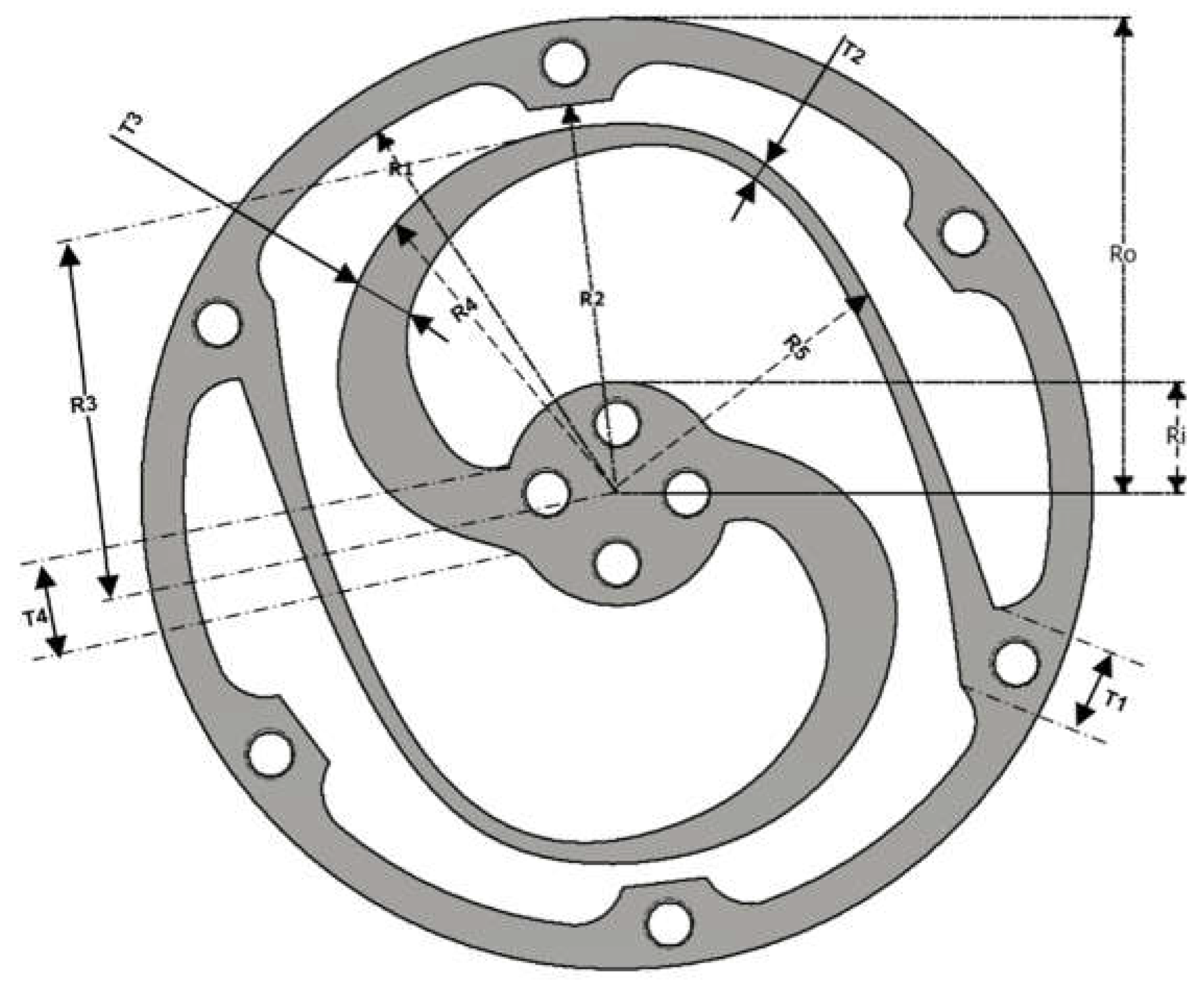
This section describes the schematic design of the torsion spring. The design process starts with the creation of a concept for the search range of parameters, which are used to develop the schematic design of the torsion spring. A specific shape for the flexible element D, which consists of two worm-shaped lamellae separated by a distance of π from each other, is specified and illustrated in
Figure 5 and
Figure 6. The elastic elements are ached lamellae distributed in a wide loop between the inner and outer circles, acting as worm-shaped lamellae.
Constant parameters such as the radius of the inner (Ri) and outer rings (Ro), the inner radius of the outer ring (R1 and R2), and the distance (T1) between the rings are defined and depend on the selected hole size (M4.5) and the allowable edge distance from the hole. A rule of thumb is to place the bolt hole center 1.6 times the bolt diameter from the edge of the outer ring to avoid exceeding the tear-out strength.
Considering each replication of the lamellae block, the distances along the path of the lamellae from the center are defined as R3, R4, and R5. T2, T3, and T4 define the widths of lamellae at different locations along their paths. The thickness of the spring module is labeled with a "t". Each of these variables has a distinct impact on the spring’s flexibility, stability, and overall strength. Hence, it is possible to optimize a parameter based on the FEM experimental design methodology.
Table 3 summarizes the design parameters, with minimum and maximum allowable bounds and a minimum increment for each parameter, which are adopted into the search space for the optimization process using the finite element method (FEM).
3.3. Finite Element Method (FEM) Based Design Approach
In the design of a torsion spring, a finite element method (FEM) based approach was used to determine the stress distribution and deformation of the chosen spring topology. ANSYS Workbench 2022 R2 was used for the linear static structural analysis to ensure the highest equivalent stress was below the material's yield strength (1400 MPa with a safety factor of 1.65) under the applied torque of 45.7 Nm. The FEM simulation was part of an iterative design optimization process to find the optimal values for the search space parameters (as shown in
Table 3) while reducing weight and size with maintaining the required spring characteristics.
The FEM verification was based on four criteria: spring stiffness meeting design requirements, limit deformation angle meeting requirements, spring topology meeting DFM design guidelines, and no failure under the maximum torque with equivalent stress below the material's yield strength.
In the analysis, two boundary conditions were defined based on the actual mounting state of the torsion spring: the inner ring of the spring was fixed to the ground through its four drill holes, and the torque was applied to the external surface of the outer ring. The spring stiffness (K) was calculated by dividing the applied torque by the angular deformation [
22], based on Hooke’s law [
49]:
Where T is the torque and is the angular position.
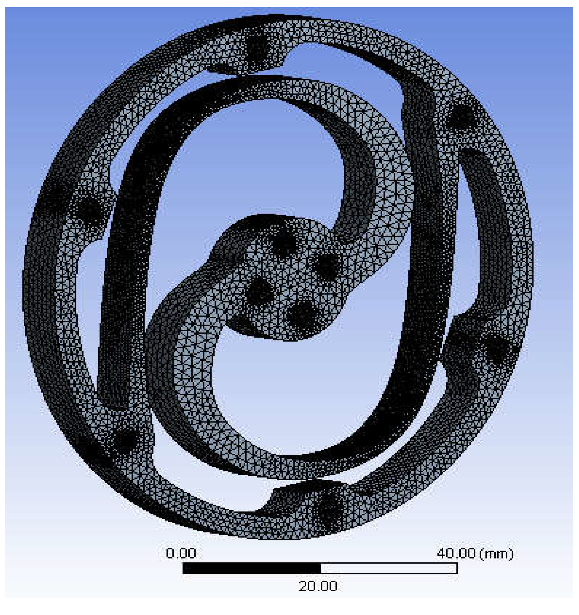
The mesh utilized in this study is a single layer swept tetrahedral mesh. The finer mesh surrounds lamellae and holes, which have more curvature and smaller cross-sections, and the coarser mesh surrounds the outer ring, where predicted lower stresses occur. The 3D subdomain was generated by starting with the torsion spring's surface and sweeping the resulting face mesh through the body, employing advanced function sizes for proximity and curvature, as well as a high smoothing element.
Figure 7 illustrates this mesh. Regulations for the structured mesh were made based on a convergence approach to ensure steady mesh generation throughout the computation of many variations.
A mesh analysis of torsion springs was performed before starting the optimization procedure to assure the precision of the optimization results. The convergence approach was conducted to ensure a steady mesh generation throughout the optimization process. The element quantity was found to fluctuate from 100,000 to 500,000 nodes. The results of the convergence test showed the appropriate number of nodes ranging from
250,000 to 300,000 nodes. Exactly 292,842 nodes were found and used for the actual optimization, with a maximum size set to 1.5 mm, and the minimum size of 0.017587, as shown in
Table 4.
3.4. Design Verification using FEM
A finite element method (FEM) analysis was performed to verify and optimized the design parameters of the selected topology structure within the search space that shown in
Table 3. In Ansys Workbench, multiple finite element analysis simulations were conducted on the optimized structure to evaluate its performance under an applied torque of 45.7 Nm. The results showed that the weakest part of the structure was located at the root of the lamellae segment and near the inner ring, where stress concentration was high. To increase the overall strength and achieve smooth stress distribution, the weakest area was manually strengthened. The thin parts of the lamellae segments were accordingly reinforced, resulting in an optimized structure. The optimal geometry parameters are shown in
Table 5, and the optimal topology of the spring module is depicted in
Figure 8.
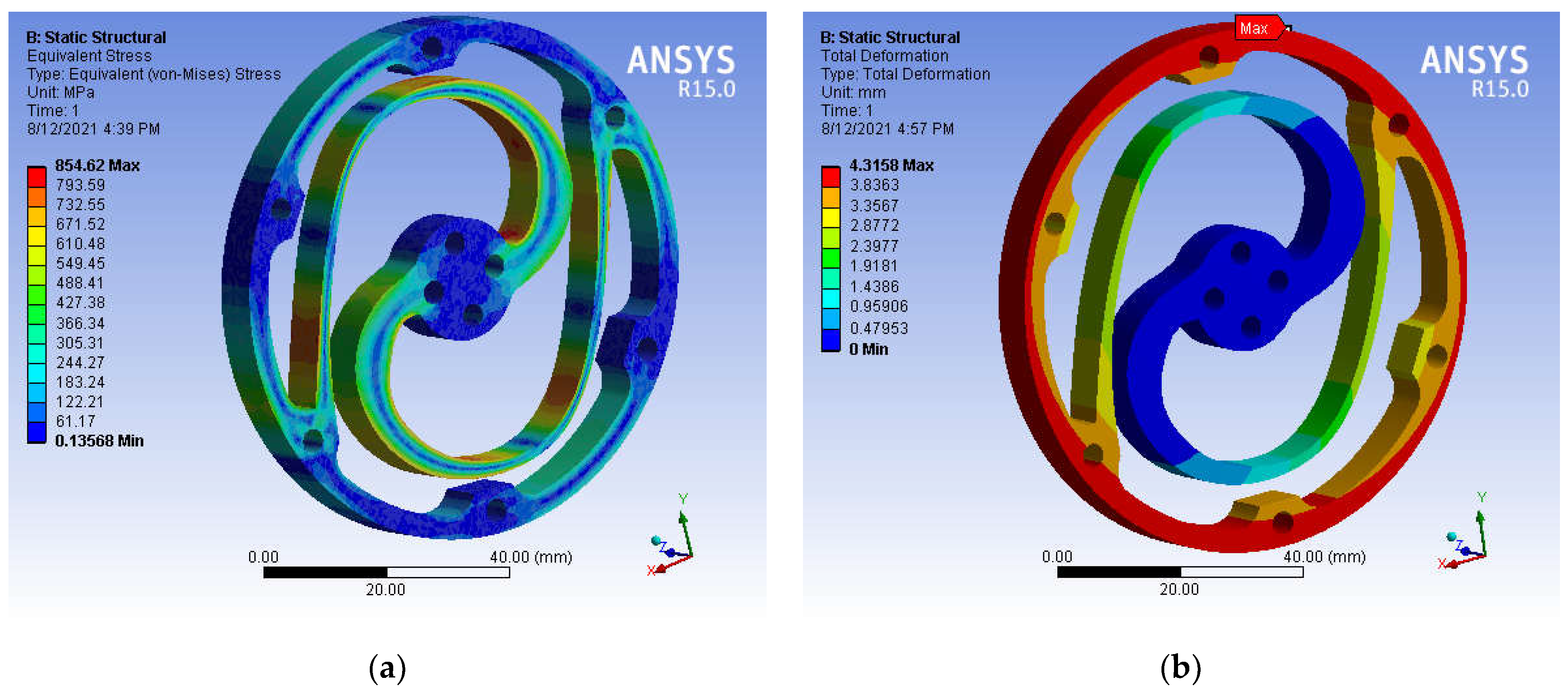
The thickness of the component was set to an optimal value of 8 mm to maximize material usage and reduce stress, while avoiding excessive bulkiness. The results of the FEM simulation for the optimal parameters, including the 1:1 Von Mises stress and the spring module deformation, are shown in
Figure 9. The stress distribution in the spring body is within the acceptable range, with a Von Mises stress of 854 MPa and a maximum deformation of 4.3158 mm under the applied torque of 45.7 Nm.
4. Experimental Characterization of Torsion Spring
4.1. Manufacturing of the Torsion Spring
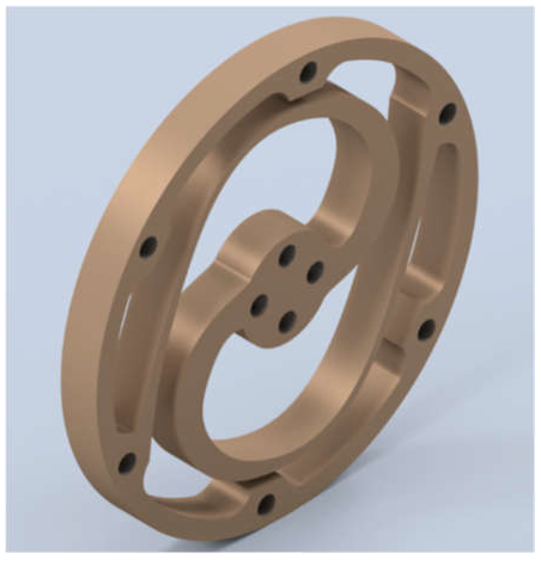
The torsion spring model was optimized using the FEM design technique as shown in
Figure 10. In the early stages of spring design, design for manufacturing (DFM) considerations were taken into account to provide feedback on the spring design and avoid any challenges during the final prototype manufacturing. With DFM, potential issues can be addressed early in the design stage, saving time and money. As a result, the decision to select the appropriate cutting machine for the manufacturing process was made based on DFM considerations and recommendations.
The waterjet cutting machine was selected to manufacture the spring prototype, over other methods such as wire electrical discharge machining (WEDM), CNC, and laser cutting, because the waterjet cutting process can cut irregular shapes, curved shapes, and internal holes with good edge quality and precision [
50]. The waterjet technique is also a cold-cutting process that cuts materials without deformation or heat-affected zones [
50]. The available waterjet cutting machine in Malaysia has a cutting accuracy of ±0.1 mm and a nozzle diameter (stream size) up to 2 mm. The limitations of the used waterjet machine were considered in the early design stage.
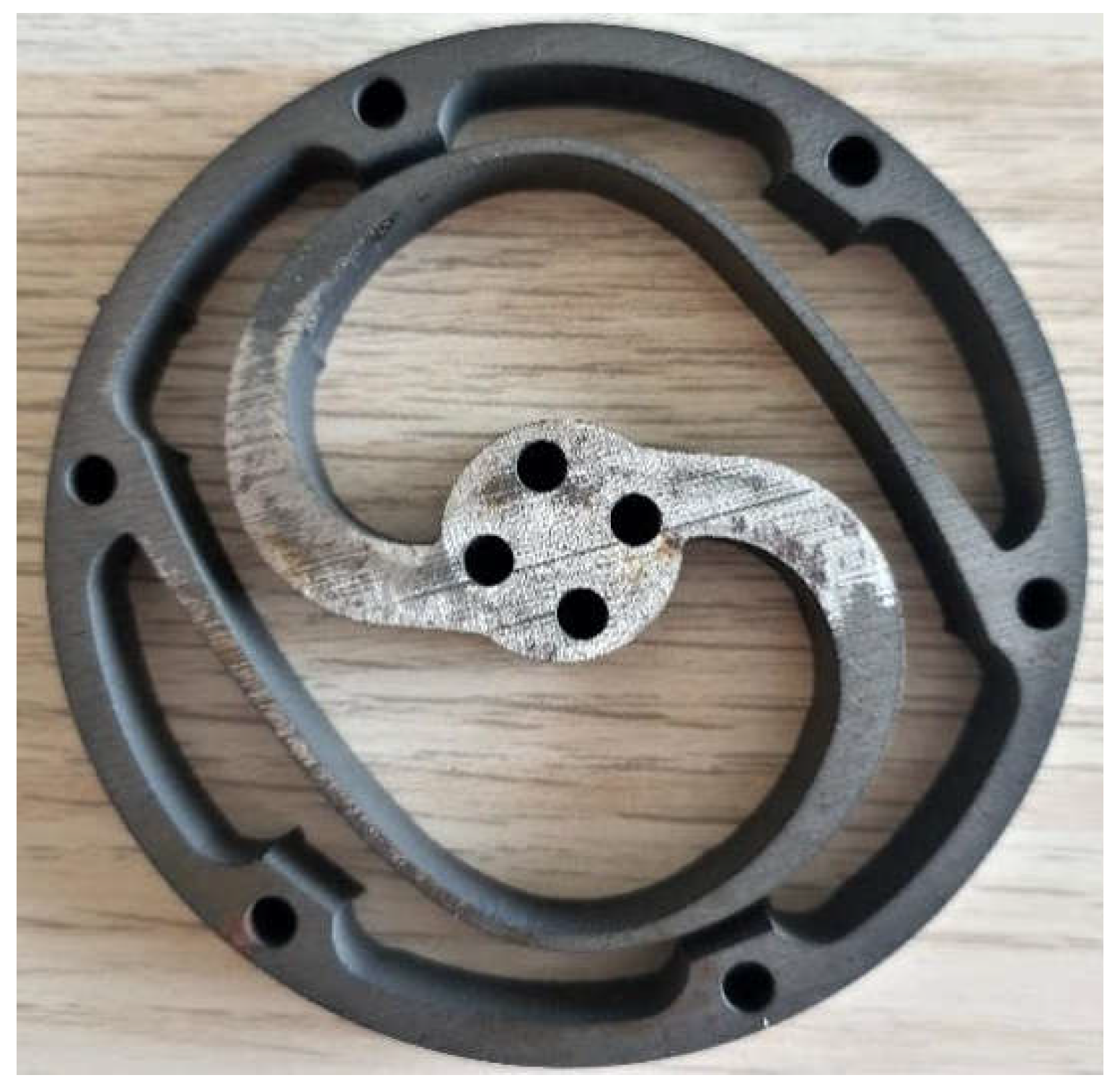
Finally, the optimized torsion spring module was manufactured from an 8 mm AISI 4140 alloy steel plate, as shown in
Figure 10.
4.2. Test Rig Setup
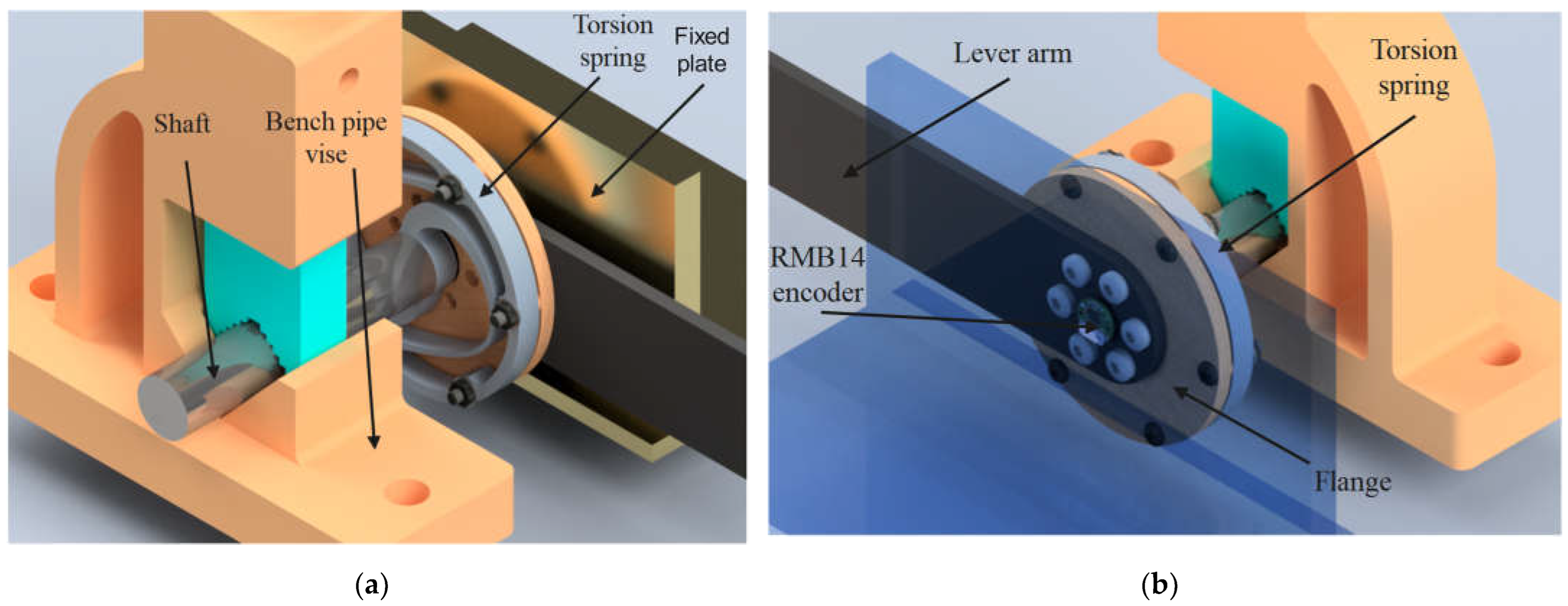
A test rig was established to evaluate the torsion spring's elastic properties in accordance with the operating procedure of the ES-RSEA actuator. The test rig consisted of a fixed plate, torsion spring, bench pipe vise, steel wire, RMB14 angular magnetic encoder (12-bit absolute, RLS), flange, lever arm, and shaft. The components of the test rig were selected for their low cost, efficiency, and ease of assembly. A 3D CAD rendering of the test rig with the torsion spring is shown in
Figure 11.
To secure the torsion spring's inner diameter to the steel shaft, four bolts were used. The steel shaft was then clamped in place using the pipe jaws of a bench vise, as illustrated in
Figure 11. The exterior diameter of the spring was attached to a movable flange on the other side using six bolts. Torque was applied to the exterior diameter of the spring through a lever arm, which was attached to the central axis of the flange. A known mass could be added to the integrated steel wire, which was attached to the lever arm 300 mm away from the spring, to produce the estimated torque.
The RMB14 angular magnetic encoder (12-bit absolute, RLS) was selected to track the angular deflection of the torsion spring during the experiment. The lowest measurement increment was 0.0879 degrees, based on the encoder's resolution (12 Bit). This resolution was sufficient for detecting the deflection angle for stiffness testing, as the applied torque did not fluctuate dynamically. The magnet of the encoder was positioned on the circular side of the lever arm, parallel to the spring axis, and installed on the fixed plate.
The load was applied to the moving lever arm, which had a length of 300mm, through a 1.2mm diameter 304 stainless steel wire rope. The mass of the load was increased in increments of 1.47Nm from 0.5kg to 15.5kg, corresponding to a range of applied torques from 1.47Nm to 45.6Nm. The resulting torque was transmitted to the outer ring of the torsional spring, while the inner ring was mounted to the frame, with a diameter of 20 mm. The actual angular deflection was measured using a RMB14 angular magnetic encoder, which was 12-bit absolute and provided by RLS.
5. Results and Discussion
5.1 Stiffness Characteristics
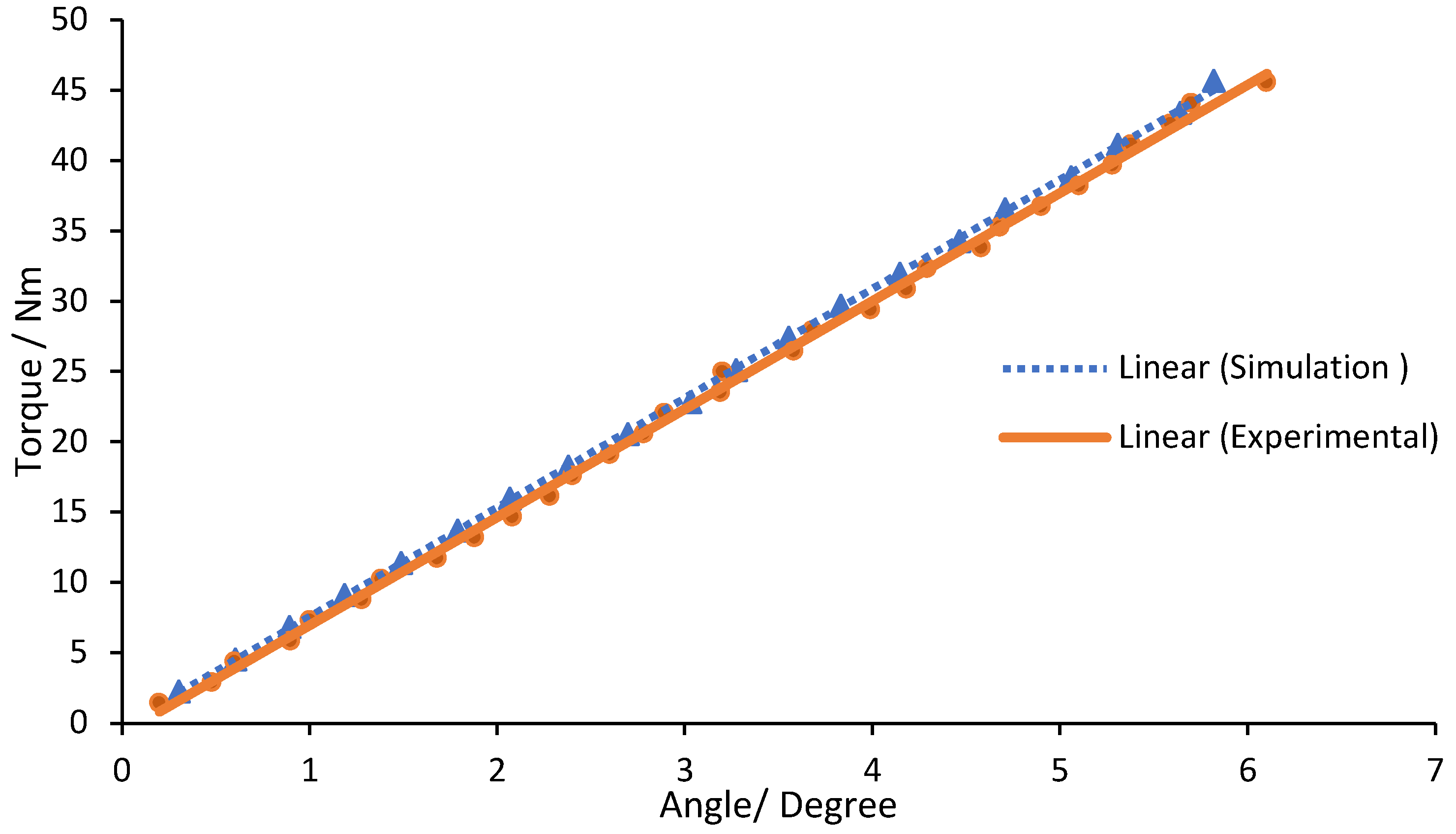
This section explains the findings from the simulations and experiments performed on the torsion spring. The torsion spring's characteristics were accurately predicted using the FEM calculation model, as shown by the simulation results. The maximum vertical displacement of the outer ring was measured to be 4.3158 mm at the rotation arc deformation value, corresponding to a maximum angular rotation of 0.10155 rad under a peak torque of 45.7 Nm. A total of 20 simulations were performed to analyze the linearity of the torque-displacement relationship, applying torque from 2.285 Nm to 45.7 Nm with a step of 2.285 Nm. The resulting values for each simulation are reported with a dashed line in
Figure 12. The results show linear characteristics with a torsion stiffness of 445.19 Nm/rad and a high linear regression
value of 0.9997, comparing with theoretical stiffness
of 450 Nm/rad. The spring stiffness matches its design requirement with an error of 1.07%, corresponding to an error between theoretical value and the simulated value, calculated as
.
The torsion spring prototypes were tested experimentally. The torque versus angular rotation characteristics of the simulation and experimental torsion spring modules are shown in
Figure 12. Five tests were carried out at each torque level, allowing the spring element to return to its initial position following each measurement. The resulting average values are depicted in
Figure 12. After linear regression for the data collected, the experimental results show a linear relationship between torque and angular rotation with
value of 0.9987. The experimental result revealed that the measured spring stiffness
of 440 Nm/rad is roughly 1.166% less than the stiffness
calculated from the FEM simulations of 445.19 Nm/rad, computed as
The results of the torque-displacement relationship demonstrate that the stiffness characteristic response remarkably linear within the examined torque range, reflecting over 99% linearity and no significant backlash. The hysteresis was difficult to determine, but the spring deformation was stable and symmetric, as the curve plot illustrates in figure. The difference between the experimental and simulated results was less than 2%, which is considered a trivial difference and may be attributed to good manufacturing accuracy, accurate FEM-based design optimization, and matching material properties between the prototype and CAD module.
5.2 Overall Spring Characteristics
The proposed torsion spring has a weight of 140 g, a maximum angular deflection of 5.8 degrees, an applied torque of 45.7 Nm, and a compact design with a thickness of 8 mm and an outer diameter of 85 mm. The experimental stiffness of the spring was measured at 440 Nm/rad, and the weight-to-torque ratio was found to be 3.
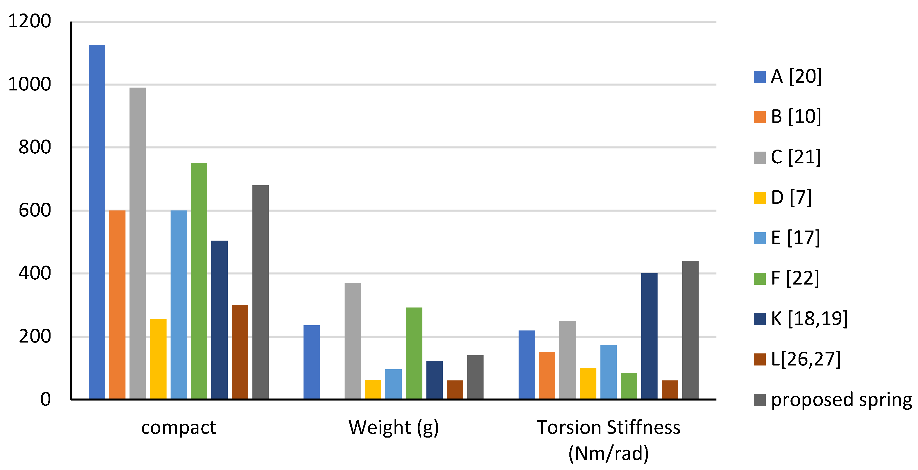
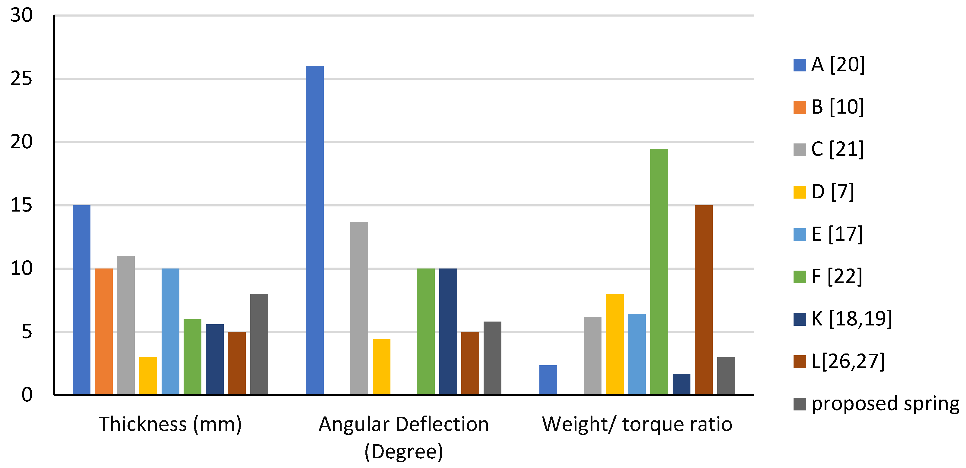
The proposed spring was compared to other existing spring models listed in
Table 1 (A, B, C, E, F, K, and L) based on five key characteristics: material cost, compactness, weight-to-torque ratio, stiffness, and maximum angular deflection. The comparison results are shown in
Figure 13 and
Figure 14 in bar charts.
The results of the comparison with other spring models in the literature showed that the proposed spring has the highest stiffness. It has a lower weight-to-torque ratio compared to all springs except spring K. Despite being slightly heavier than springs L, K, E, and D, it can still be considered light compared to springs A, C, and F. The maximum angular deflection was higher than springs L and D but lower than springs A, C, F, and K due to its high stiffness. The torque resolution is proportional to the stiffness, and the maximum angular deflection is inversely proportional to the stiffness. Therefore, the proposed spring has a higher torque resolution than springs A, C, F, and K and a lower torque resolution than springs L and D.
In terms of compactness, the proposed spring has a smaller size compared to springs L, K, E, D, and B, but larger than springs A, C, and F. The compactness of a spring can be measured by the volume of the spring, calculated by multiplying its cross-sectional area (diameter) by its length.
It's important to note that spring F has a higher maximum angular deflection compared to the proposed spring, but the proposed spring has better characteristics in terms of weight, weight-to-torque ratio, and compactness.
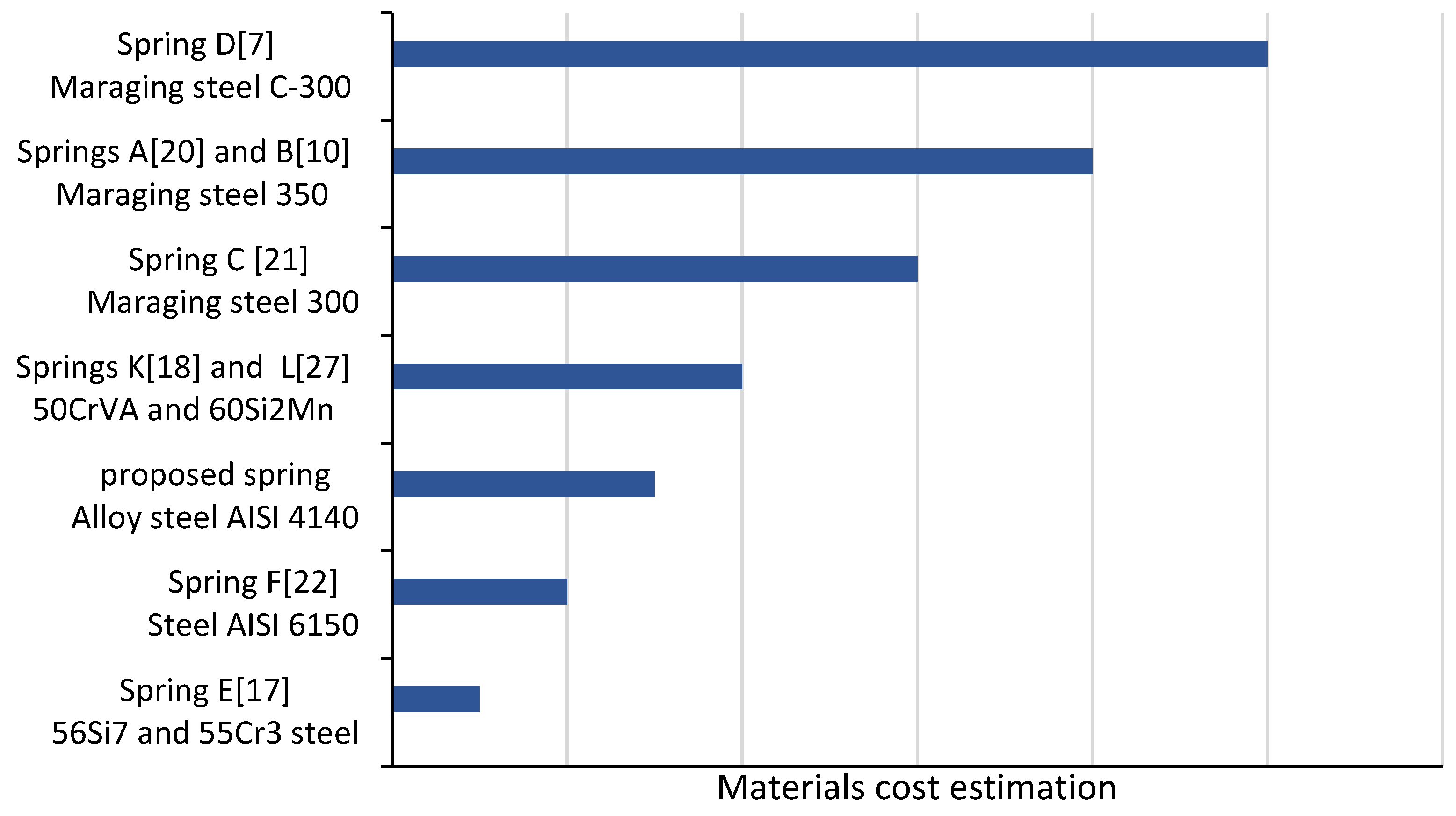
The cost of the materials used in the proposed spring, chromium-molybdenum alloy steel AISI 4140, was estimated to be more cost-effective compared to other materials used in the literature except springs E and F, as shown in
Figure 15. Spring E does not have better characteristics overall compared to the proposed spring. The proposed spring has better characteristics than spring F in terms of weight and weight-to-torque ratio, and similar characteristics in terms of compactness. The only characteristic where spring F exceeds the proposed spring is in maximum angular deflection.
Overall, the proposed torsion spring has excellent characteristics, including the highest stiffness and a lower weight-to-torque ratio, and its material cost is more cost-effective compared to other springs.
6. Conclusion and Recommendations
In conclusion, the torsion spring module presented in this study provides a cost-effective and efficient solution for the lumbar support exoskeleton of the ES-RSEA. The prototype of the torsion spring was designed, modeled, and evaluated based on its spring and stiffness characteristics, incorporating DFM principles for lightweight, compact, cost-efficient, and easy-to-manufacture design. The FEM-based design optimization was validated through comparison of the simulation results with experimental results, which showed good agreement. The torsion spring demonstrated a maximum torque capacity of 45.7 Nm and a stiffness of 440 Nm/rad, consistent with the FEM simulations with a deviation of roughly 1.166%. The stiffness characteristics were linear with minimal deviation between measurements and simulations. The chosen material, AISI 4140 alloy steel, was found to be cost-effective compared to other materials in the literature. The proposed torsion spring has a good balance between stiffness, weight-to-torque ratio, and compactness, making it a promising candidate for use in the lumbar support exoskeleton. Overall, the study demonstrates the excellent characteristics of the proposed torsion spring, including high stiffness, low weight-to-torque ratio, and cost-effectiveness compared to other springs in the literature.
Based on the results of this study, it is recommended that the proposed torsion spring design be considered for applications that require high stiffness, low weight-to-torque ratio, and cost-effectiveness. Additionally, further research can be conducted to modify the parametric CAD modeling design for use in different SEA applications, such as pHRI and humanoid or walking robots. The DFM-based design methodology used in this study can also be applied to other elastic elements in compliance actuators with appropriate modifications. It is also suggested to consider trimming the unmounted part of the outer ring to reduce the overall mass by up to 20% as a potential enhancement.
Author Contributions
Conceptualization, O.A.; methodology, O.A.; software, O.A. ; validation, O.A., R.G., M.T., and H.Y.; formal analysis, O.A.; investigation, O.A.; resources, R.G., and H.Y.; data curation, O.A.; writing—original draft preparation, O.A.; writing—review and editing, O.A, M.T., R.G., and M.G.; visualization, O.A., R.G., M.T., and H.Y.; supervision, R.G., H.Y., and M.T.; project administration, R.G., and H.Y.; funding acquisition, O.A, R.G. M.T., H.Y. and M.G. All authors have read and agreed to the published version of the manuscript.
Funding
We have not received any funds
Data Availability Statement
All the relevant data are within the paper and its supporting information files.
Acknowledgments
The authors wish to acknowledge the support by University of Malaya for the facility and equipment support under faculty of engineering Grant (GPF023A-2018).
Conflicts of Interest
The authors declare no conflict of interest. The funders had no role in the design of the study; in the collection, analyses, or interpretation of data; in the writing of the manuscript, or in the decision to publish the results.
References
- Brinckmann, P.; Frobin, W.; Biggemann, M.; Hilweg, D.; Seidel, S.; Burton, K.; Tillotson, M.; Sandover, J.; Atha, J.; Quinnell, R. Quantification of overload injuries to thoracolumbar vertebrae and discs in persons exposed to heavy physical exertions or vibration at the work-place. Clin. Biomech. 1994, 9, S3–S83. [Google Scholar] [CrossRef]
- Edlich, R.F.; Winters, K.L.; Hudson, M.A.; Britt, L.D.; Long, W.B. Prevention of Disabling Back Injuries in Nurses by the Use of Mechanical Patient Lift Systems. J. Autom. Inf. Sci. 2004, 14, 14. [Google Scholar] [CrossRef] [PubMed]
- Baltrusch, S.J.; Houdijk, H.; van Dieën, J.H.; van Bennekom, C.A.M.; de Kruif, A.J.T.C.M. Perspectives of End Users on the Potential Use of Trunk Exoskeletons for People With Low-Back Pain: A Focus Group Study. Hum. Factors: J. Hum. Factors Ergon. Soc. 2020, 62, 365–376. [Google Scholar] [CrossRef]
- de Looze, M.P.; Bosch, T.; Krause, F.; Stadler, K.S.; O’sullivan, L.W. Exoskeletons for industrial application and their potential effects on physical work load. Ergonomics 2016, 59, 671–681. [Google Scholar] [CrossRef]
- Robla-Gómez, S.; Becerra, V.M.; Llata, J.R.; González-Sarabia, E.; Torre-Ferrero, C.; Pérez-Oria, J. Working Together: A Review on Safe Human-Robot Collaboration in Industrial Environments. IEEE Access 2017, 5, 26754–26773. [Google Scholar] [CrossRef]
- Pratt, G.A.; Williamson, M. Series elastic actuators. In Proceedings of the Proceedings 1995 IEEE/RSJ International Conference on Intelligent Robots and Systems. Human Robot Interaction and Cooperative Robots, 1995; vol.391, pp. 399–406. [Google Scholar]
- Carpino, G.; Accoto, D.; Sergi, F.; Tagliamonte, N.L.; Guglielmelli, E. A Novel Compact Torsional Spring for Series Elastic Actuators for Assistive Wearable Robots. J. Mech. Des. 2012, 134, 121002. [Google Scholar] [CrossRef]
- Pratt, J.; Krupp, B.; Morse, C. Series elastic actuators for high fidelity force control. Ind. Robot. Int. J. Robot. Res. Appl. 2002, 29, 234–241. [Google Scholar] [CrossRef]
- Eitel, E. The Rise of Soft Robots and the Actuators that Drive Them. machIne desIgn Sep 12 2013, pp. 30-36.
- Stienen, A.H.A.; Hekman, E.E.G.; ter Braak, H.; Aalsma, A.M.M.; van der Helm, F.C.T.; van der Kooij, H. Design of a Rotational Hydroelastic Actuator for a Powered Exoskeleton for Upper Limb Rehabilitation. IEEE Trans. Biomed. Eng. 2009, 57, 728–735. [Google Scholar] [CrossRef] [PubMed]
- Zhang, T.; Huang, H.H. A Lower-Back Robotic Exoskeleton: Industrial Handling Augmentation Used to Provide Spinal Support. IEEE Robot. Autom. Mag. 2018, 25, 95–106. [Google Scholar] [CrossRef]
- Hyun, D.J.; Lim, H.; Park, S.; Nam, S. Singular Wire-Driven Series Elastic Actuation with Force Control for a Waist Assistive Exoskeleton, H-WEXv2. IEEE/ASME Trans. Mechatronics 2020, 25, 1026–1035. [Google Scholar] [CrossRef]
- Al-Dahiree, O.S.; Ghazilla, R.A.R.; Tokhi, M.O.; Yap, H.J.; Albaadani, E.A. Design of a Compact Energy Storage with Rotary Series Elastic Actuator for Lumbar Support Exoskeleton. Machines 2022, 10, 584. [Google Scholar] [CrossRef]
- Al-Dahiree, O.S.; Ghazilla, R.A.R.; Yap, H.J.; Tokhi, M.O.; Yoong, G.W. Modeling and Dynamic performance of Energy Storage -Rotary Series Elastic Actuator for Lumbar Support Exoskeleton. In Proceedings of the 2022 IEEE 10th Conference on Systems, Process & Control (ICSPC), Malaysia, 17 December 2022; pp. 208–216. [Google Scholar]
- Lagoda, C.; Schouten, A.C.; Stienen, A.H.A.; Hekman, E.E.G.; van der Kooij, H.; IEEE. Design of an electric Series Elastic Actuated Joint for robotic gait rehabilitation training. In Proceedings of the 2010 3rd Ieee Ras and Embs International Conference on Biomedical Robotics and Biomechatronics, New York, NY, USA, 2010; pp. 21–26. [Google Scholar]
- Knox, B.T.; Schmiedeler, J.P. A Unidirectional Series-Elastic Actuator Design Using a Spiral Torsion Spring. J. Mech. Des. 2009, 131, 125001. [Google Scholar] [CrossRef]
- Irmscher, C.; Woschke, E.; May, E.; Daniel, C. Design, optimisation and testing of a compact, inexpensive elastic element for series elastic actuators. Med Eng. Phys. 2018, 52, 84–89. [Google Scholar] [CrossRef]
- Zhang, T.; Tran, M.; Huang, H. Admittance Shaping-Based Assistive Control of SEA-Driven Robotic Hip Exoskeleton. IEEE/ASME Trans. Mechatronics 2019, 24, 1508–1519. [Google Scholar] [CrossRef]
- Zhang, T.; Xia, J. Development of a Clutchable Series Elastic Actuator for Robotic Hip Exoskeleton. In Proceedings of the 2019 IEEE International Conference on Cybernetics and Intelligent Systems (CIS) and IEEE Conference on Robotics, Automation and Mechatronics (RAM), 18–20 November 2019; pp. 269–274. [Google Scholar]
- Lagoda, C.; Schouten, A.; Stienen, A.; Hekman, E.; Kooij, H.v.d. Design of an electric series elastic actuated joint for robotic gait rehabilitation training. In Proceedings of the 2010 3rd IEEE RAS & EMBS International Conference on Biomedical Robotics and Biomechatronics, 2010; pp. 21–26. [Google Scholar]
- Accoto, D.; Carpino, G.; Sergi, F.; Tagliamonte, N.L.; Zollo, L.; Guglielmelli, E. Design and Characterization of a Novel High-Power Series Elastic Actuator for a Lower Limb Robotic Orthosis. Int. J. Adv. Robot. Syst. 2013, 10, 359. [Google Scholar] [CrossRef]
- dos Santos, W.M.; Caurin, G.A.; Siqueira, A.A. Design and control of an active knee orthosis driven by a rotary Series Elastic Actuator. Control. Eng. Pract. 2017, 58, 307–318. [Google Scholar] [CrossRef]
- Paine, N.; Mehling, J.S.; Holley, J.; Radford, N.A.; Johnson, G.; Fok, C.; Sentis, L. Actuator Control for the NASA-JSC Valkyrie Humanoid Robot: A Decoupled Dynamics Approach for Torque Control of Series Elastic Robots. J. Field Robot. 2015, 32, 378–396. [Google Scholar] [CrossRef]
- Cummings, J.P.; Ruiken, D.; Wilkinson, E.L.; Lanighan, M.W.; Grupen, R.A.; Sup, F.C. A Compact, Modular Series Elastic Actuator. J. Mech. Robot. 2016, 8, 041016. [Google Scholar] [CrossRef]
- Zhang, S.; Zhu, Q.; Wu, J.; Xiong, R.; Gu, Y. Design and Compliance Control of Rehabilitation Exoskeleton for Elbow Joint Anchylosis. In Proceedings of the 2020 IEEE/ASME International Conference on Advanced Intelligent Mechatronics (AIM), 6–9 July 2020; pp. 1896–1901. [Google Scholar]
- Wang, L.; Du, Z.; Dong, W.; Shen, Y.; Zhao, G. Intrinsic Sensing and Evolving Internal Model Control of Compact Elastic Module for a Lower Extremity Exoskeleton. Sensors 2018, 18, 909. [Google Scholar] [CrossRef]
- Long, Y.; Du, Z.-J.; Chen, C.-F.; Wang, W.-D.; Dong, W. Development of a lower extremity wearable exoskeleton with double compact elastic module: preliminary experiments. Mech. Sci. 2017, 8, 249–258. [Google Scholar] [CrossRef]
- Yildirim, M.C.; Sendur, P.; Kansizoglu, A.T.; Uras, U.; Bilgin, O.; Emre, S.; Yapici, G.G.; Arik, M.; Ugurlu, B. Design and development of a durable series elastic actuator with an optimized spring topology. Proc. Inst. Mech. Eng. Part C: J. Mech. Eng. Sci. 2021, 235, 7848–7858. [Google Scholar] [CrossRef]
- Daniyan, I.A. Application of Design for Manufacturing and Assembly: Development of a Multifeedstock Biodiesel Processor; IntechOpen: 2018.
- Lucchetta, G.; Bariani, P.; Knight, W. Integrated Design Analysis for Product Simplification. CIRP Ann. 2005, 54, 147–150. [Google Scholar] [CrossRef]
- Anderson, D.M. Design for Manufacturability, 1st ed.; Productivity Press: New York, 2014. [Google Scholar]
- Dowlatshahi, S. An integrated manufacturing system design: an applied approach. Int. J. Prod. Econ. 1995, 42, 187–199. [Google Scholar] [CrossRef]
- Chao, N.-H. Artificial Intelligence in Engineering Design; Tong, C., Sriram, D., Eds.; Academic Press: San Diego, 1992; pp. 199–222. [Google Scholar]
- Păcurar, A.; Păcurar, R.; Erőss, B.; Popister, F.; Otel, C.C. Decreasing of the manufacturing time for a thermoforming mold by applying the DFM principles. MATEC Web Conf. 2017, 137, 01008. [Google Scholar] [CrossRef]
- Paluska, D.; Herr, H. The effect of series elasticity on actuator power and work output: Implications for robotic and prosthetic joint design. Robot. Auton. Syst. 2006, 54, 667–673. [Google Scholar] [CrossRef]
- Hurst, J.; Rizzi, A.; Hobbelen, D. Series elastic actuation: Potential and pitfalls. In Proceedings of the International Conference on Climbing and Walking Robots; 2004. [Google Scholar]
- Zolfagharian, A.; Lakhi, M.; Ranjbar, S.; Tadesse, Y.; Bodaghi, M. 3D printing non-assembly compliant joints for soft robotics. Results Eng. 2022, 15. [Google Scholar] [CrossRef]
- W. Robinson, D. Design and Analysis of Series Elasticity in Closed-loop Actuator Force Control. Doctoral dissertation, Massachusetts Institute of Technology, 2000.
- Tagliamonte, N.L.; Sergi, F.; Carpino, G.; Accoto, D.; Guglielmelli, E. ; Ieee, *!!! REPLACE !!!*, Translator; Design of a Variable Impedance Differential Actuator for Wearable Robotics Applications. In Proceedings of the IEEE/Rsj 2010 International Conference on Intelligent Robots and Systems, Taipei, Taiwan, 2010; pp. 2639–2644. [Google Scholar]
- J, Y. Control method and experimental research on elastic actuation of exoskeleton robot. Master’s thesis, Harbin Institute of Technology, 2014.
- Woo, H.; Na, B.; Kong, K. Design of a compact rotary series elastic actuator for improved actuation transparency and mechanical safety. In Proceedings of the 2017 IEEE International Conference on Robotics and Automation (ICRA); 2017; pp. 1872–1877. [Google Scholar]
- Giovacchini, F.; Vannetti, F.; Fantozzi, M.; Cempini, M.; Cortese, M.; Parri, A.; Yan, T.; Lefeber, D.; Vitiello, N. A light-weight active orthosis for hip movement assistance. In Proceedings of the Robotics and Autonomous Systems; Elsevier: Amsterdam, The Netherlands, 2015; Volume 73, pp. 123–134. [Google Scholar]
- Yu, H.; Huang, S.; Chen, G.; Pan, Y.; Guo, Z. Human–Robot Interaction Control of Rehabilitation Robots With Series Elastic Actuators. IEEE Trans. Robot. 2015, 31, 1089–1100. [Google Scholar] [CrossRef]
- Kim, S.; Bae, J. Force-Mode Control of Rotary Series Elastic Actuators in a Lower Extremity Exoskeleton Using Model-Inverse Time Delay Control. IEEE/ASME Trans. Mechatronics 2017, 22, 1392–1400. [Google Scholar] [CrossRef]
- Kong, K.; Bae, J.; Tomizuka, M. Control of Rotary Series Elastic Actuator for Ideal Force-Mode Actuation in Human–Robot Interaction Applications. IEEE/ASME Trans. Mechatronics 2009, 14, 105–118. [Google Scholar] [CrossRef]
- Wang, S.; Meijneke, C.; Kooij, H.v.d. Modeling, design, and optimization of Mindwalker series elastic joint. In Proceedings of the 2013 IEEE 13th International Conference on Rehabilitation Robotics (ICORR), 24–26 June 2013; pp. 1–8. [Google Scholar]
- Zhang, T.; Huang, H. Design and Control of a Series Elastic Actuator With Clutch for Hip Exoskeleton for Precise Assistive Magnitude and Timing Control and Improved Mechanical Safety. IEEE/ASME Trans. Mechatronics 2019, 24, 2215–2226. [Google Scholar] [CrossRef]
- Mühl, F.; Damon, J.; Dietrich, S.; Schulze, V. Simulation of induction hardening: Simulative sensitivity analysis with respect to material parameters and the surface layer state. Comput. Mater. Sci. 2020, 184, 109916. [Google Scholar] [CrossRef]
- Rychlewski, J. On Hooke's law. J. Appl. Math. Mech. 1984, 48, 303–314. [Google Scholar] [CrossRef]
- Inc., C.M. 4 Features That Make Waterjet Cutting the Right Choice for Your next Metal Fabrication Project. Available online: https://inbound.cammmetals.com/blog/4-features-that-make-waterjet-cutting-the-right-choice-for-your-next-metal-fabrication-project (accessed on 29 October 2018).
Figure 1.
Patterns of compliant elements for rotary series elastic actuators.
Figure 1.
Patterns of compliant elements for rotary series elastic actuators.
Figure 2.
ES-RSEA Configuration.
Figure 2.
ES-RSEA Configuration.
Figure 3.
Cross-Section of ES-RSEA.
Figure 3.
Cross-Section of ES-RSEA.
Figure 4.
Flowchart of the spring design process.
Figure 4.
Flowchart of the spring design process.
Figure 5.
Elastic element module topologies considered: (a) Topology A; (b) Topology B; (c) Topology C; (d) Topology D.
Figure 5.
Elastic element module topologies considered: (a) Topology A; (b) Topology B; (c) Topology C; (d) Topology D.
Figure 6.
Morphology of the chosen topology.
Figure 6.
Morphology of the chosen topology.
Figure 8.
Optimized module for torsion spring.
Figure 8.
Optimized module for torsion spring.
Figure 9.
FEM results: (a) Module deformation (mm); (b) Von Mises stress (MPa).
Figure 9.
FEM results: (a) Module deformation (mm); (b) Von Mises stress (MPa).
Figure 10.
Manufactured torsion spring.
Figure 10.
Manufactured torsion spring.
Figure 11.
3D Rendering of the testbed of torsion spring: (a) Front view; (b) Back view.
Figure 11.
3D Rendering of the testbed of torsion spring: (a) Front view; (b) Back view.
Figure 12.
Characteristic of spring stiffness.
Figure 12.
Characteristic of spring stiffness.
Figure 13.
Spring characteristics of compactness, weight, and torsion stiffness.
Figure 13.
Spring characteristics of compactness, weight, and torsion stiffness.
Figure 14.
Spring characteristics of thickness, angular deflection and weigh to torque ratio.
Figure 14.
Spring characteristics of thickness, angular deflection and weigh to torque ratio.
Figure 15.
Materials cost estimation for torsion springs.
Figure 15.
Materials cost estimation for torsion springs.
Table 1.
Comparisons of The Main Features of The Existing Torsion Springs Design.
Table 1.
Comparisons of The Main Features of The Existing Torsion Springs Design.
| Spring |
Diameter (mm) |
Thickness (mm) |
Weight (g) |
Torque (Nm) |
Torsion Stiffness (Nm/rad) |
Angular Deflection (Degree) |
Material |
Weight/ torque ratio |
Application |
| A [20] |
75 |
15 |
235 |
100 |
219 |
26 |
Maraging steel 350 (AISI grade 18Ni, 2320 MPa) |
2.35 |
Gait rehabilitation training (stroke survivors) |
| B [10] |
60 |
10 |
Unknown |
50 |
150 |
Unknown |
Maraging steel 350 (AISI grade 18Ni, 2.32 GPa) |
Unknown |
Upper limb rehabilitation |
| C [21] |
90 |
11 |
370 |
60 |
250 |
13.7 |
Maraging steel 300 (nominal yield stress 2.0 GPa) |
6.17 |
Gait assistance and human augmentation |
| D [7] |
85 |
3 |
61.5 |
7.7 |
98 |
4.4 |
Maraging steel C-300 |
7.98 |
Gait assistance and human augmentation |
| E [17] |
60 |
10 |
96 |
15 |
172(3) |
Unknown |
56Si7 and 55Cr3 steel |
6.4 |
Rehabilitation, assistive device for motorically impaired stroke-patients |
| F [22] |
125 |
6 |
292 |
15 |
84 |
10 |
Chromium–Vanadium steel (AISI 6150) |
19.46 |
Stroke rehabilitation, robot-assisted gait training |
| K [18,19] |
90 |
5.6 |
121.7 |
70 |
400 |
10 |
50CrVA |
1.7 |
Gait assistance and human augmentation |
| L[26,27] |
60 |
5 |
60 |
4 |
60.2 |
4.98 |
60Si2Mn |
15 |
Gait assistance exoskeleton |
Table 2.
Design Requirements of the Torsional Spring.
Table 2.
Design Requirements of the Torsional Spring.
| Design Parameter |
Desired Value for the Proposed Design |
| Output torque of the RSEA |
45.7 Nm |
| Maximum thickness |
10 mm |
| Maximum outer diameter |
85 mm |
| Minimum inner diameter |
20 mm |
| Torsional spring stiffness |
200–800 Nm/rad |
| Maximum weight |
150 g |
| Spring material |
Low-alloy steel AISI 4140 |
| yield strength |
1400 MPA |
| Angular deflection |
5.8 Degree |
| Weight to torque ratio |
3 g/Nm |
Table 3.
Search space parameters for the chosen topology.
Table 3.
Search space parameters for the chosen topology.
| Parameter |
Minimum |
Maximum |
Minimum Increment |
| R3 |
25 |
33 |
0.2 |
| R4 |
22 |
32 |
0.2 |
| R5 |
23 |
33 |
0.5 |
| T2 |
1 |
4 |
0.1 |
| T3 |
3 |
7 |
0.1 |
| T4 |
4.5 |
16 |
0.5 |
| t |
4 |
16 |
2 |
Table 4.
Number of nodes produced for finite elements design.
Table 4.
Number of nodes produced for finite elements design.
| Mesh Property/Spring Type |
Number of Nodes Produced |
| Element Quantity Fluctuation |
100,000 to 500,000 |
| Convergence |
250,000 – 300,000 |
| Actual optimization |
292,842 |
Table 5.
Optimized parameters for the chosen topology.
Table 5.
Optimized parameters for the chosen topology.
| Parameter |
Optimized |
| R3 |
32.8 |
| R4 |
31.2 |
| R5 |
28.5 |
| T2 |
1.6 |
| T3 |
5.2 |
| T4 |
8.5 |
| T |
8 |
|
Disclaimer/Publisher’s Note: The statements, opinions and data contained in all publications are solely those of the individual author(s) and contributor(s) and not of MDPI and/or the editor(s). MDPI and/or the editor(s) disclaim responsibility for any injury to people or property resulting from any ideas, methods, instructions or products referred to in the content. |
© 2023 by the authors. Licensee MDPI, Basel, Switzerland. This article is an open access article distributed under the terms and conditions of the Creative Commons Attribution (CC BY) license (http://creativecommons.org/licenses/by/4.0/).
