1. Introduction
The vibrations of the structures that are made of isotropic and homogeneous materials has been an important subject in the study of noise control, in the aeronautical industry, in the study of fluid-solid interactions and in construction industry for double leaf partitions as building structures. When a sound wave impinges on a structure, a part of acoustic energy is reflected back into source medium, another part of the energy is dissipated in the structure and the rest of acoustic energy is transmitted through the structure into the other medium. In building acoustic applications, the reflected acoustic energy builds up a reverberant sound field in the source room that in turn vibrates the walls of the buildings. The vibrations in the common walls between adjacent rooms radiate sound directly into the receiver room. The vibrations in the other walls of the source room travel as structure-borne noise to all walls of the receiving room and radiate sound into the receiver room.
Complex structures may be modelled as systems that are made of individual plate like elements. The theory of vibration of porous and non-porous structures is a well-known branch of engineering mechanics. Previous works on classical theory of the plate [
1,
2,
3,
4,
5,
6,
7] has investigated vibration of isotropic and anisotropic plates for various boundary conditions. The vibration of porous plates can be described using two coupled equations [
8], which are based on Biot’s stress-strain relations [
9,
10] and which introduce two types of compressional waves (‘fast’ and ‘slow’) and a shear wave. The thickness of plate is assumed to be smaller than the wavelength and that interaction can take place between the slow waves and the bending waves in the plate. They also ignored the amplitude of the fast wave. Galerkin’s variational techniques were applied to porous plates [
11,
12,
13], considering a classical set of trial functions obtained from the linear combination of trigonometric and hyperbolic functions for various boundary conditions. The effects of fluid loading on the vibration of porous rectangular plates and on their radiated sound power was investigated by including an extra term into the equations for the porous plate vibration, corresponding to the additional external force acting on the plate [
14]. Previous study on low frequency vibration of porous plates [
15] has demonstrated the existence of low frequency absorption coefficient resonance in configurations consisting of clamped poroelastic plates with an air cavity between the plates and a rigid termination. An analytical model that considers the effect of perforations and the effect of the flexural vibrations in the plates has been formulated and used to calculate the insertion loss in the absence, and in the presence of air flow [
16,
17].
Important progress in predicting acoustic radiation from solid structures including plates and beams has been made in the last three decades. Many previous studies have focused on the calculation of the radiation efficiency of these structures [
18,
19,
20,
21] and the radiation of sound from a baffled, rectangular plate with edges elastically restrained against deflection and rotation [
22,
23]. The models used for the radiation efficiency of plate-like radiators, ranged from very simple ones based on modal average expressions to refined calculations of the radiation impedance matrix with cross-modal coupling have been evaluated, and developed a new approach based on Taylor’s expansion of the Green’s function [
24]. Variational method that is based on the Rayleigh-Ritz model, can be used to determine the radiation of sound from the plates that are immersed either in a light fluid or in a heavy fluid by reducing the quadruple integral into a double integral using a specific change of variable and by integrating the double integral with a numerical method using Gaussian quadrature formulae [
25,
26,
27,
28]. An investigation was carried out on composite recycled glass bead panels to assess their suitability for civil engineering application, especially in noisy urban environments, either as structural panel components that also offer acoustic insulation or as dedicated noise barriers for outdoor applications [
29]. Recently, vibroacoustic properties of thin plates was studied for different boundary conditions [
30,
31].
The aim of this paper is to investigate the vibrational and acoustical parameters of thin plates that are made of fibreglass. The deflection of fibreglass plate was predicted at different locations on the plate using the theory of the plate for simply supported and clamped boundary conditions. Computational simulations were carried out to determine deformations of the plate in 3-Dimentional for different frequency ranges for simply supported and clamped boundary conditions. Here, vibroacoustic indicators including the radiation efficiency, the mean square velocity, and the radiated sound power were computed for a square fibreglass plate. Furthermore, the radiation impedance matrix was predicted for simply supported boundary condition by using equations for Eigen-functions and Green-function.
2. Theory
2.1. Deflection of a fibreglass plate
Many different types of waves can be seen in solid structures when they are excited by different ways of stressing. Acoustic wave motion in solid structures stores energy in shear as well as in compression. The solid structures should have energy storage capability in the form of potential energy and kinetic energy to allow acoustic wave propagation through their mediums. Potential energy is stored in solid structure parts that have undergone elastic deformation while kinetic energy is stored in any part of the medium that has mass in motion.
When a uniform fibreglass plate is subjected to a transverse, time dependent force density
F(
x,
y,
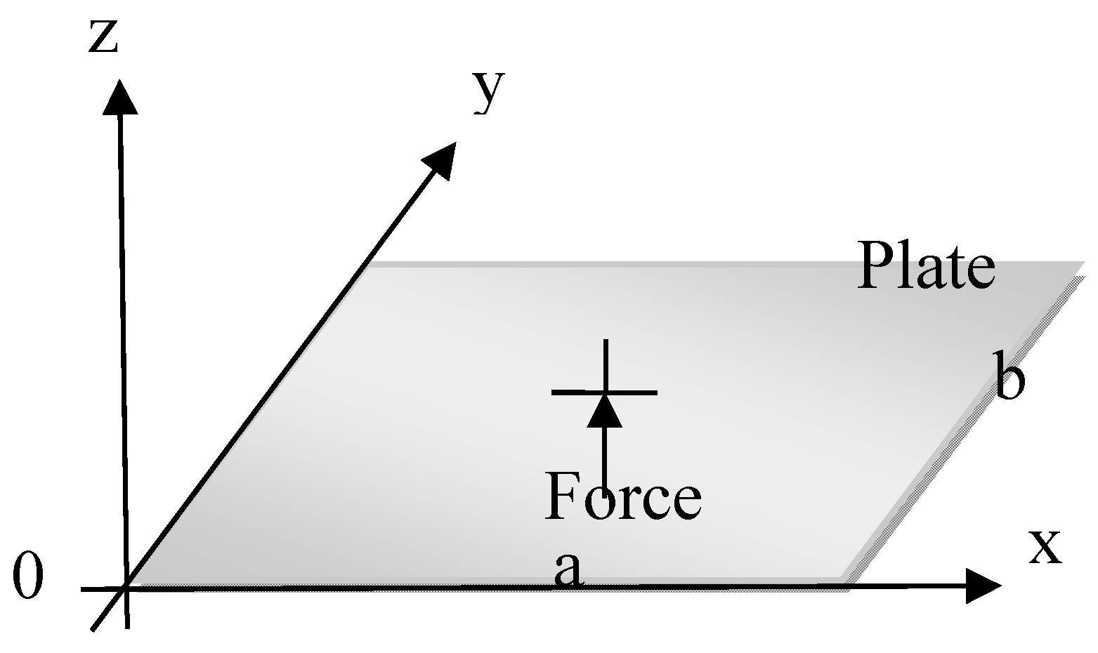
t) the transverse deflection of the plate is governed by the fourth order differential equation. The transverse vibration under free wave conditions stems entirely from inertial loading. A thin, baffled square plate of dimension
a x
b (along aces
x and
y, respectively) and uniform thickness
h is considered in this study. The plate displacement induced by bending waves is in the direction of
z-axis and is function of time. The geometry of the plate is shown in
Figure 1.
The flexural wave equation for fibreglass thin plate is given as follow.
where
is the transverse plate deflection,
is the second order derivative of the plate deflection,
is the flexural rigidity,
and
in the system of coordinates (
x, y) with
x and
y parallel to the plate sides of length
a and
b respectively,
is the mass density,
E is the Young’s modulus of the plate, and
is the Poisson ratio of the plate.
The plate deflection
for harmonic wave motion is expressed in Equation 2.
where
is the unknown coefficients,
m and
n are the modes and they are equal to 0, 1, 2, 3
…., and
are the beam functions in
x and
y direction respectively. The beam functions have been selected to satisfy different boundary conditions at the edges of the plate. An appropriate trigonometric function for vibrating beams has been used for
different boundary conditions. For simply supported plates, the beam functions are given as
and
which should satisfy the equations of equilibrium.
The boundary conditions for simply supported edges of the plate are and . The shape of each mode of vibration of plate can be determined from Equation (2) by knowing the relative values of and the values of functions.
In the static and dynamic analysis, the excitation function
F (
x,
y) has been expanded into double infinite sine series of variables
x and
y for each value of the couple (m, n) by using the equation below;
where
are the expansion coefficients.
By inserting (2) and (3) into (1), the unknown coefficient
Amn can be obtained as follow.
where
is the angular frequency of the plate.
Trigonometric functions have been used to expand the plate deflection for clamped non-porous fibreglass plate. These functions are called beam functions and they are given by.
where
and
are the frequency parameters corresponding to the
mth and
nth normal modes of characteristic equation. The constants
, and
have been determined from the boundary conditions at four edges of the plate in
x and
y direction respectively, and allow any condition involving simply supported, and clamped edges.
2.2. Acoustic radiation from a fibreglass plate
Mean square velocity is the squared velocity normal to the surface of the plate in each frequency band and it is averaged over time and the surface area of the plate. It expresses the behaviour of the vibration of the plate. Mean square velocity of thin fibreglass plate is defined as a time-space average of the square vibrational velocity of plate, and it is given by the Equation (6).
where
,
a and
b are the coordinates of plates in
x and
y directions, respectively, and
S is the surface area of the plate.
The total sound field that is generated by vibrating plates can be expressed in terms of the distribution of sound pressure over a given surface. The radiated sound power expresses the sound energy radiated into the surrounding environment by vibration of the plate. It can be obtained from the integration of the sound intensity over the plate surface. The radiated sound power of thin fibreglass plate is given by the Equation (7).
where
is the surface acoustic pressure, which is often called Rayleigh integral, and is given by the Equation (8).
where
is the Green function and it is given by the Equation (9);
where
k is the wave number, and
R is the distance between points given by the Equation (10).
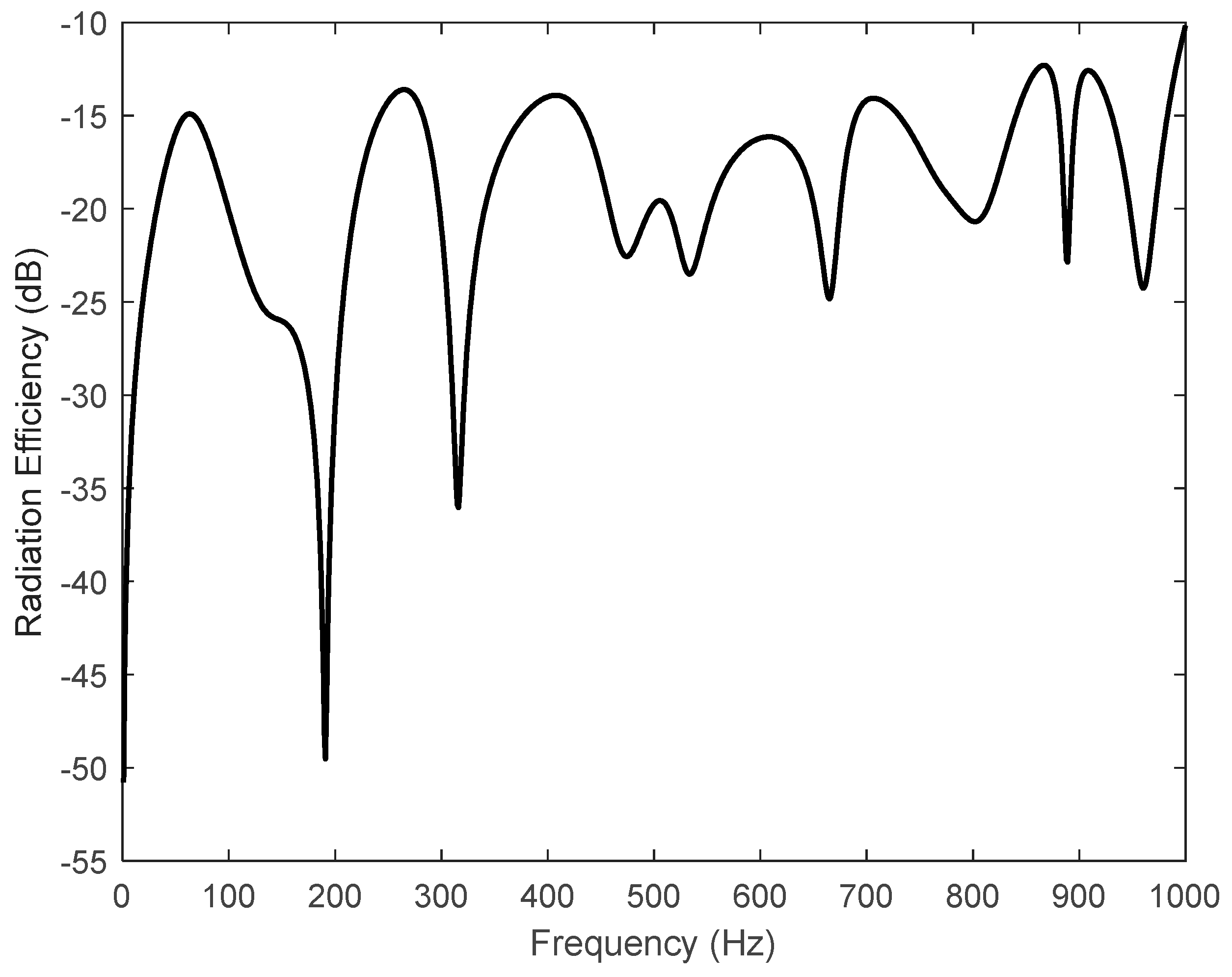
The size and shape of the vibrating plate play an important role to determine the radiation efficiency of the plate. The radiation efficiency of the plate is small at low frequencies because of larger wavelength while the radiation efficiency approaches unity at higher frequencies because of smaller wavelength of sound waves. The radiation efficiency expresses the ratio of the vibration energy (mean square velocity) transformed into acoustic energy (sound power). The radiation efficiency of the plate does not depend on the amplitude of vibrating structure. It can be obtained using analytical methods, and it is given by the Equation (11).
Where Z is the characteristic impedance of air.
2.3. Radiation impedance matrix of the plate
The coefficients of the acoustic radiation impedance of a baffled plate are given by [
22]:
where
is known as the acoustic radiation impedance between the normal modes (
m, n) and (
p, q),
is the Green function defined,
is the fluid density, and
is the eigenfunctions in the case of the simply supported boundary condition given by Equation (13);
The acoustic radiation impedance shows the influences of the sound pressure in the (m, n) mode on the plate system vibrating in the (p, q) mode. A Gaussian quadrature scheme with 30 terms of functions in each direction (x, y) has been used to compute the radiation impedance matrix. When the variables and , for which go to infinity, care has been taken to avoid singularity. The singularity at the origin has been avoided by taking G (0, 0) = 0. The direct and cross coupling terms of the radiation impedance matrix are normalized by the characteristic impedance (), where is the air density and is the sound speed in the air.
3. The results of plate vibration
A baffled square fibreglass plate has been excited by a point force
F(
x,
y,
t) which is applied at
x0 = 0.25 m, and
y0 = 0.25 m from a corner of the plate. The responses have been calculated at the locations given by
x = 0.25 m and
y = 0.25 m, and at
x = 0.15 m and
y = 0.15 m respectively. The magnitude of the force used to vibrate the plate was 1 Newton. The vibration response of the plate has been predicted in the 0-1000 Hz frequency range using a MATLAB code. The properties of the plate used for numerical analysis are given in the
Table 1.
The plate deflection has been predicted for values of normal characteristic modes
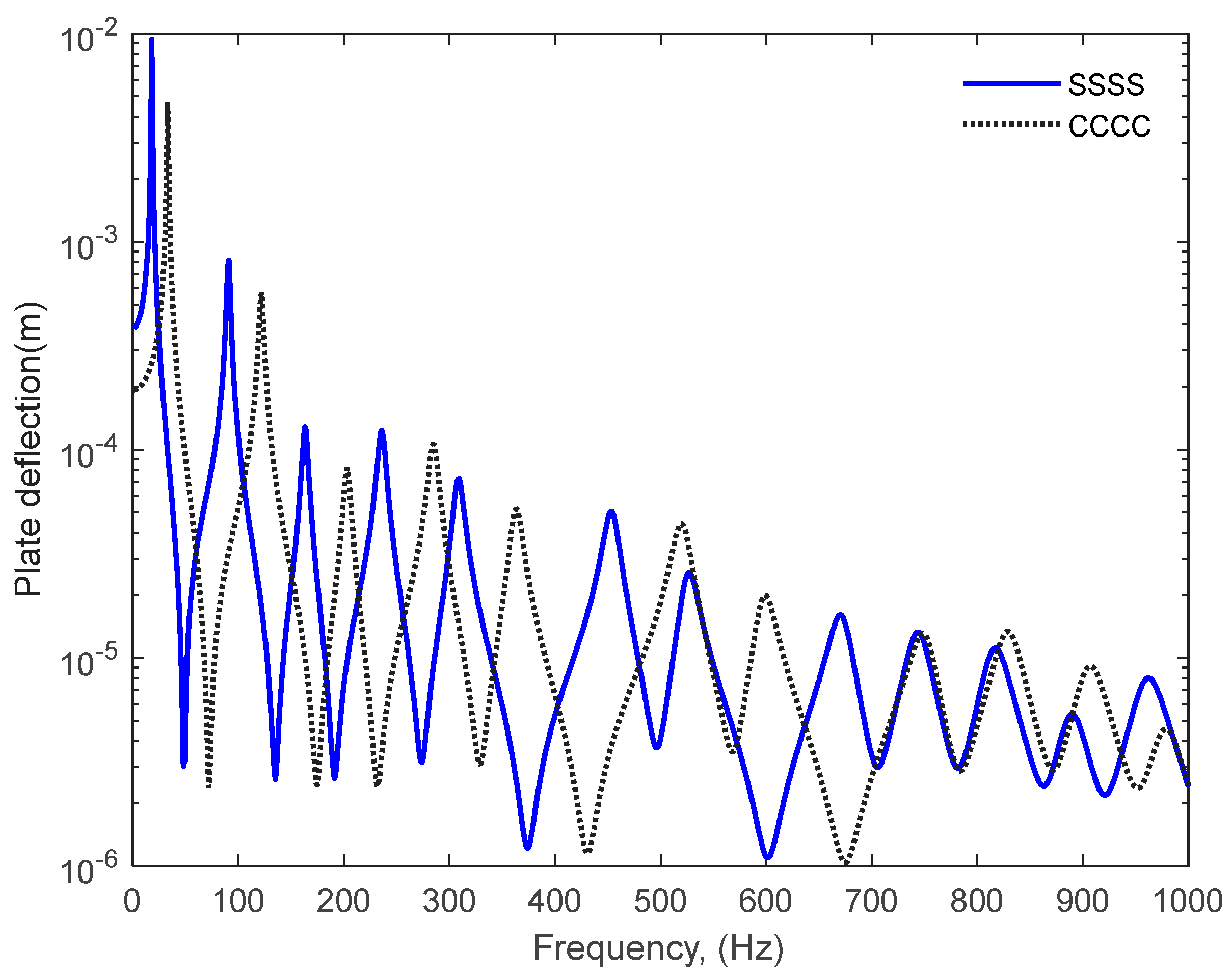
(m, n) up to 30. The vibration responses of a simply supported and clamped fibreglass plate plotted against frequency are compared in
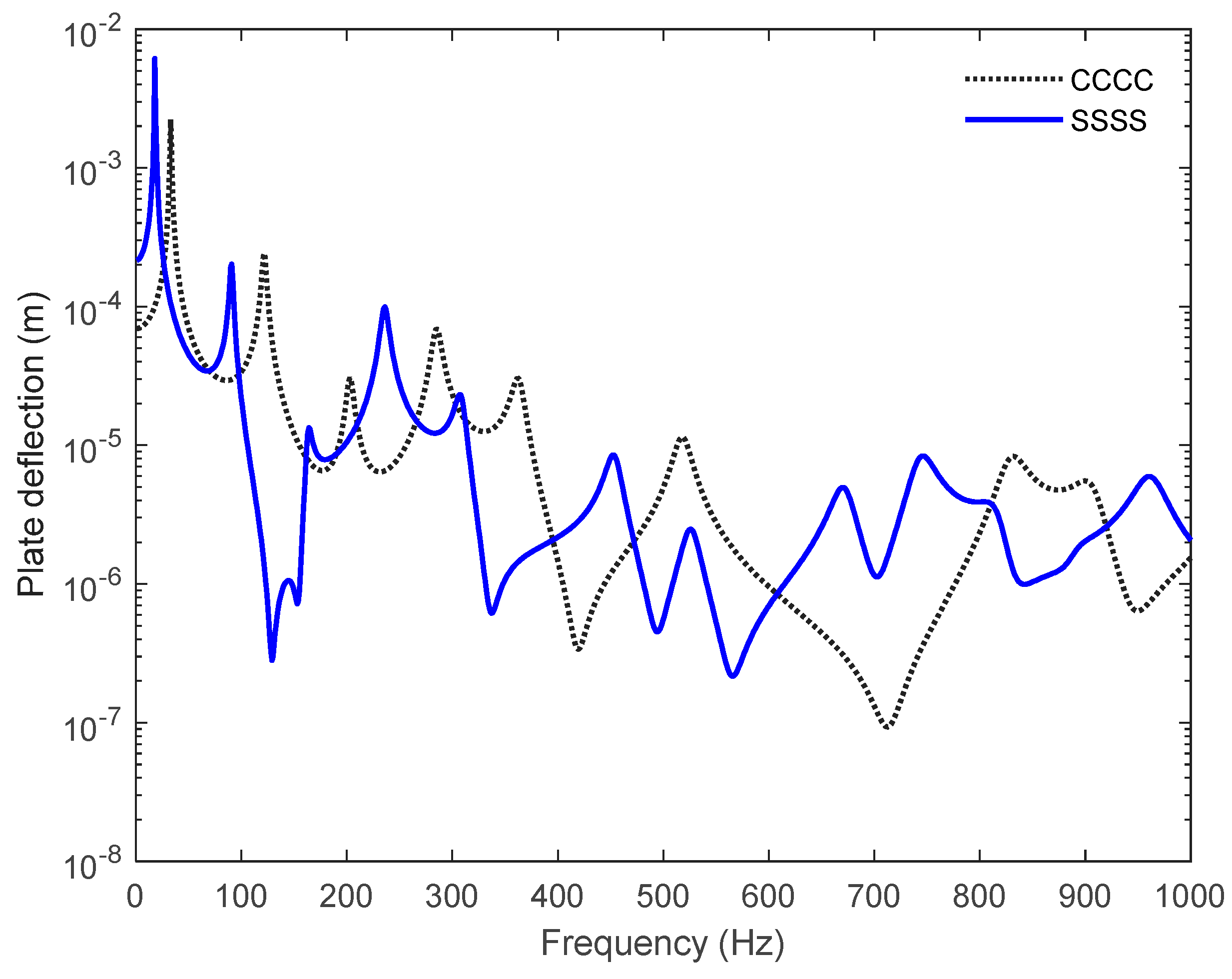
Figure 2. The responses observed are somewhat exponentially decaying sinusoidal wave signals. The first and second resonance frequencies has been observed at 18 Hz and 91 Hz for simply supported plate respectively while in case of clamped plate, the first and second resonance frequencies has been observed at 33 Hz and 121 Hz respectively. Clamping the plate at four edges delayed first resonance of the plate by 15 Hz and second resonance of the plate by 30 Hz while it reduces the amplitude of the plate deflection throughout the frequency range. The deflections of the fibreglass plate have been also calculated at a point where
x = 0.15 m and
y = 0.15 m as shown in
Figure 3. It shows that only the amplitude of resonances changes at lower frequencies while at higher frequencies the resonance frequency and its amplitude change [
31].
3-D deformations of thin fibreglass plate for simply supported boundary condition are computed using a MATLAB code, at centre of the plate for 100 Hz, 500 Hz and 1 kHz, and their corresponding results are shown in
Figures 4a, b, and c respectively. 3D deformations for clamped fibreglass plate are shown in
Figure 5a,b, and c respectively. Sixteen modes in each direction have been used to compute the 3D deformations and contour velocity of the fibreglass plate. Vertical line at the centre of the plate shows the location where the force is applied to the plate. The results clearly show that different modal deformations at 100 Hz, 500 Hz and 1 kHz frequencies can be observed for simply supported and clamped plate boundary conditions. 3D deformation in
Figure 4a corresponds to first resonance frequency while the visualisation of the deformation in
Figure 4b corresponds to first and second resonances. When the frequency increases, the number of the plate resonances increase which leads more sound energy being attenuated by vibrating plate.
The square velocities corresponding to 3D deformations of the plate that are shown in
Figure 4 and
Figure 5 are given in
Figure 6 and
Figure 7. Point dot shows the location of the force applied to the plate. Dark red contours show the high-pressure areas (compression) while dark blue contours show the minimum pressure areas (decompression).
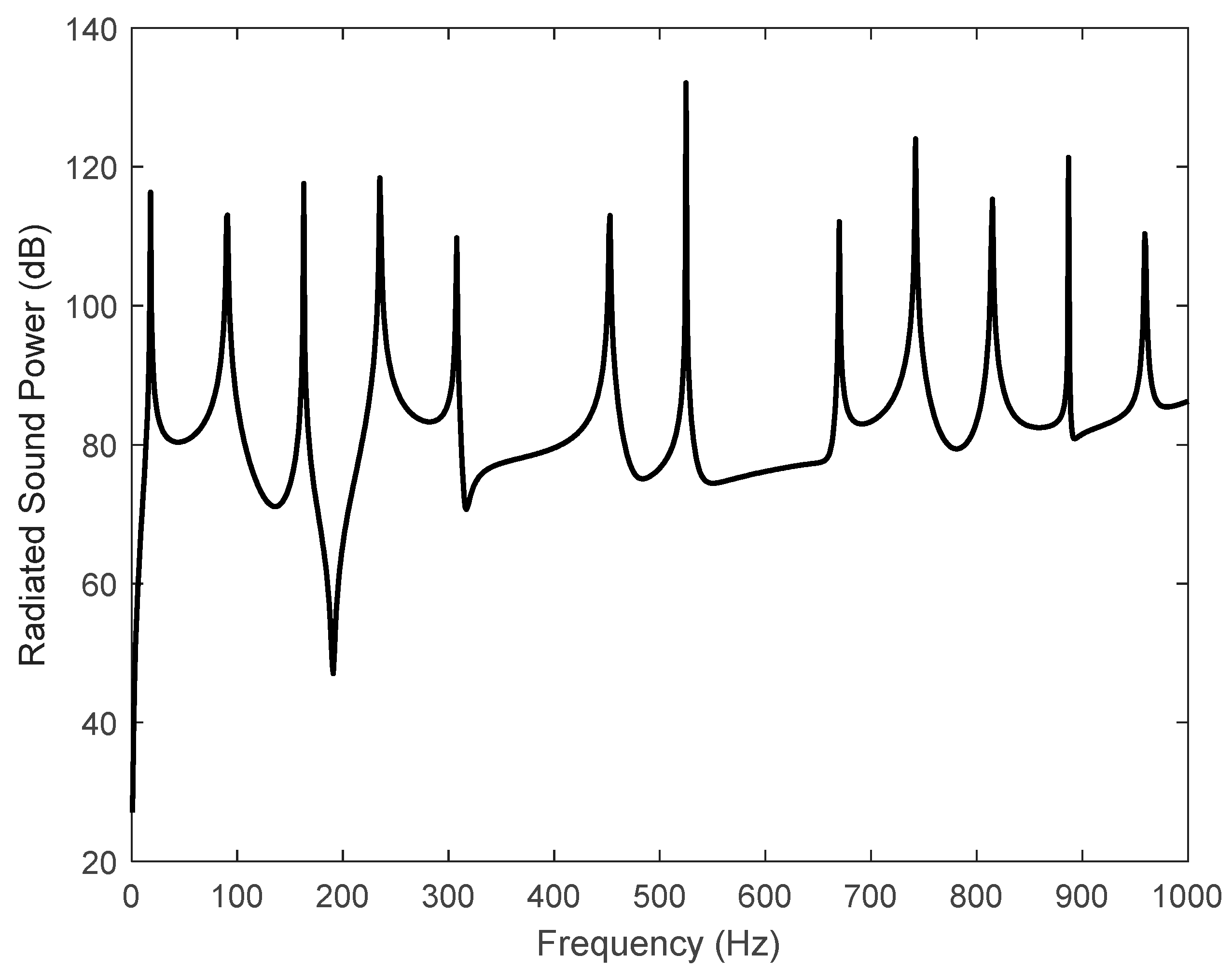
If the plate deflection given by Equation (2) is solved, then the mean square velocity of the plate can easily be predicted. The mean square velocity of fibreglass plate is shown in
Figure 8 while the predicted real part of the radiated sound power is shown in
Figure 9 [
30]. The peaks observed in frequency dependent mean square velocity and radiated sound power curves correspond to twelve resonances seen in plate deflection for simply supported boundary condition in
Figure 2. The radiation efficiency of the plate has been calculated by using the radiated sound power and the mean square velocity of the plate. The radiation efficiency of a square simply supported fibreglass plate is shown in
Figure 10.
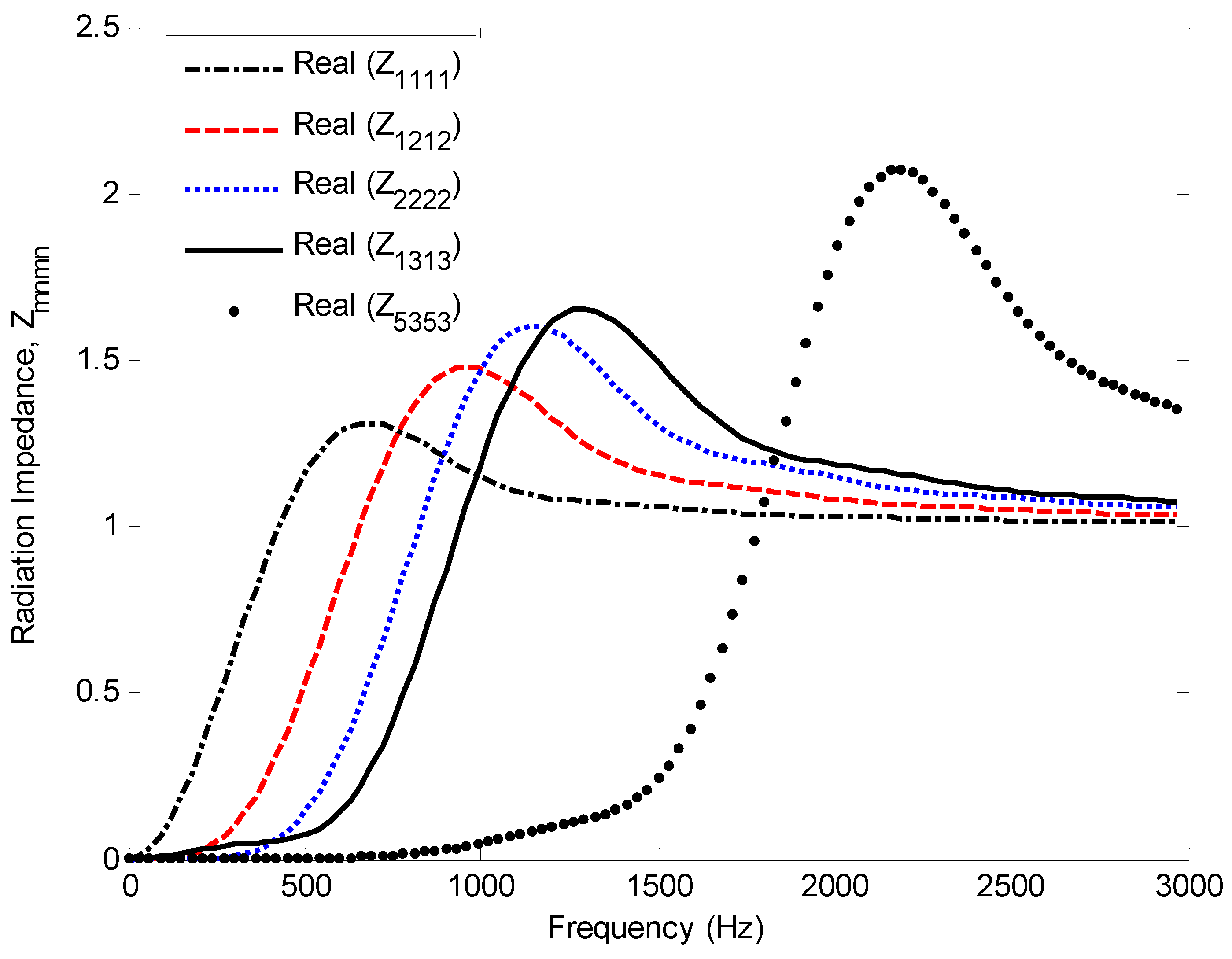
The direct terms (
) of the radiation impedance matrix are shown in
Figure 11. When higher values of (
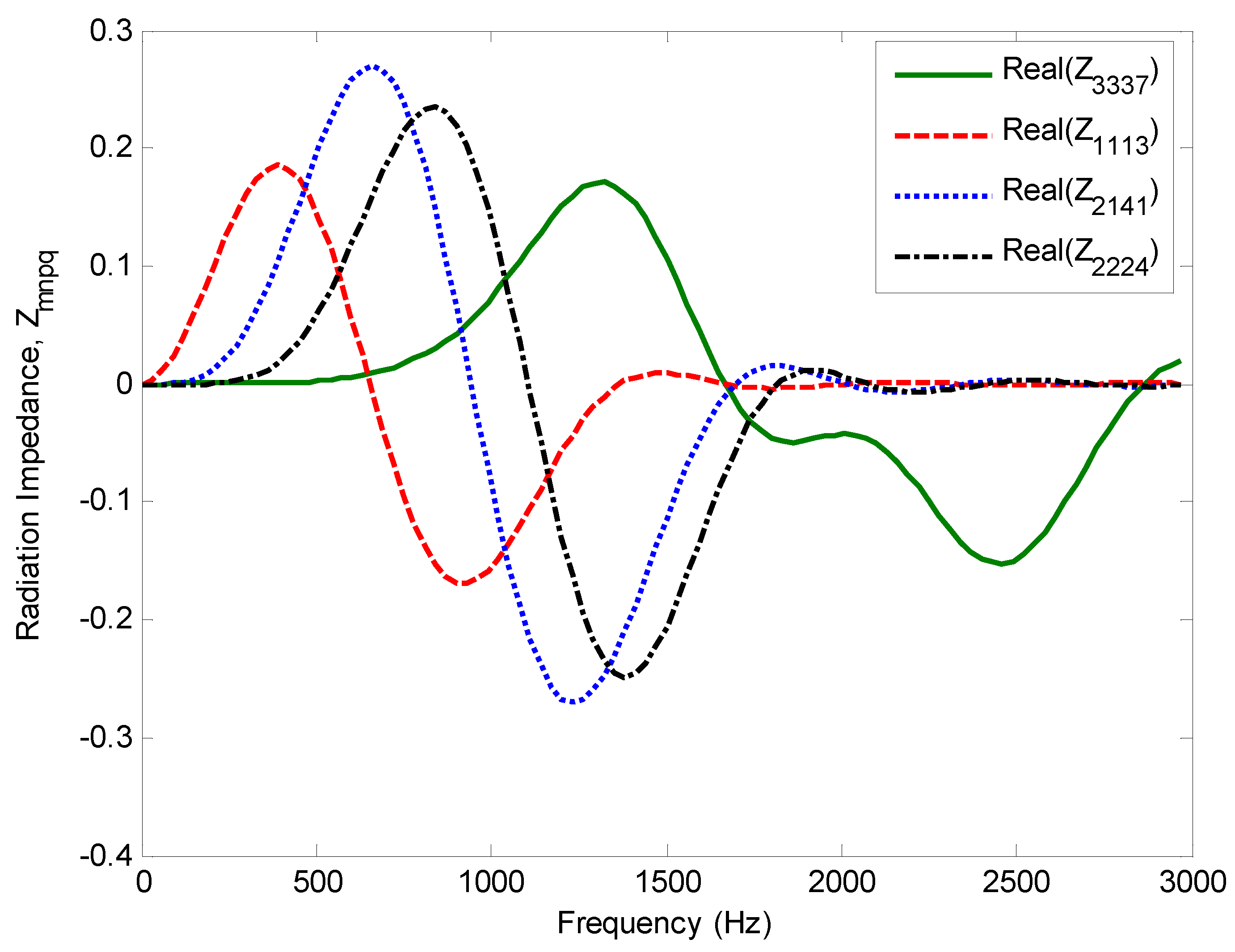
m, n) are used in the calculations, the radiation impedance matrix is equal to zero at low frequency. The cross-coupling terms
are shown in
Figure 12. The values of
m, n, p, and
q vary between
0 and
N. These figures show that the predicted radiation impedance matrix exhibits a smooth variation in terms of frequency. The real part of the radiation impedance matrix (direct terms) is the radiation resistance and expresses the radiation damping of the plate structure while the imaginary part of the radiation impedance matrix (cross coupling terms) is the radiation reactance and expresses the added mass of gas on its structure.
4. Conclusion
An investigation of the vibrational and acoustical parameters of thin fibreglass plate that is made of fibreglass has been carried out. The deflection of the fibreglass plate has been computed using the classical theory of the vibrating plate for simply supported and clamped boundary conditions at difference locations on the plate surface. Computational simulations have been carried out to determine deformations of the plate in 3D and their corresponding square velocities for different frequency ranges for simply supported and clamped boundary conditions. It has been shown that clamping the plate at four edges delayed first resonance of the plate by 15 Hz and second resonance of the plate by 30 Hz.
Vibroacoustic indicators including the radiation efficiency, the mean square velocity, and the radiated sound power have been computed for a square fibreglass plate. The radiation impedance matrix has been calculated and the direct and cross coupling terms of it have been normalized using characteristic impedance. The real part of the radiation impedance matrix is the radiation resistance and expresses the radiation damping of the plate structure.
The findings show that fibreglass plate could be applied to dampen the vibration of machine and structural vibration of buildings. In addition, fibreglass plates could be utilized to sandwich building structures to form panels in order to attenuate airborne sound and to lower sound transmission of structural borne noise.
Acknowledgments
Acknowledgement: This work was supported by London South Bank University Acoustic Research Centre.
References
- M. D. Waller, "Vibrations of Free Square Plates: Part I Normal Vibrating Modes", Proceedings of the Physical Society of London, 1939, 51, 831–844.
- M. D. Waller, "Vibrations of Free Square Plates: Part 11, Compounded Nom1 Modes", Proceedings of the Physical Society of London, 1940, 52, 452–455.
- G. B. Warburton, "The Vibration of Rectangular Plates", Proceedings of the Institution of Mechanical Engineers, 1954, 168, 371–384.
- R. F. S. Hearmon, "The Fundamental Frequency of Vibration of Rectangular Wood and Plywood Plates", Proceedings of the Physical Society of London, 1946, 58, 78–92.
- R. Szilard, (1974), “Theory and Analysis of Plates”. “Classical and Numerical Methods”. Prentice-Hall, Englewood, New Jersey.
- W. Leissa, “the free vibration of rectangular plates” J. Sound Vib. 1973, 1, 257–293.
- D. Young, “Vibration of rectangular plates by the Ritz method,” Journal of Applied Mechanics 1950, 17, 448–453.
- D. D. Theodorakopoulos and D. E Beskos, “Flexural vibration of poroelastic plates,” Acta Mechanica 1994, 103, 191–203.
- M. A. Biot, “Theory of elastic wave propagation in a fluid saturated porous solid. Part I-low frequency range,” J. Acoust. Soc. Am. 1956, 28, 168–178.
- M. A. Biot, “Theory of elastic wave propagation in a fluid saturated porous solid. Part 2-higher frequency range,” J. Acoust. Soc. Am. 1956, 28, 179–191.
- P. Leclaire, A. Cummings and K. V. Horoshenkov, “Transverse vibration of a thin rectangular porous plate saturated by a fluid,” J. Sound Vib. 2001, 247, 1–18.
- P. Leclaire, K. V. Horoshenkov, M. J. Swift, and D. C. Hothersall, “The vibration response of a clamped rectangular porous plate,” J. Sound Vib. 2001, 217, 19–31.
- P. Leclaire, “Vibration of Porous Plates in Structural Acoustic Coupling Applications,” 3rd European Congress on Acoustics. 16th –20th 02, Spain. 20 September.
- H. Aygun and K. Attenborough. “Predicted effects of fluid loading on the vibration of elastic porous plates”. Acta Acoustica united with Acustica. 2007, 93, 284–289.
- H. Aygun and K. Attenborough, “Sound absorption by clamped poroelastic plates,” J. Acoust. Soc. Am. 2008, 124, 1–7.
- H. Aygun and K. Attenborough, “The insertion loss of perforated porous plates in a duct with and without mean air flow,” Applied Acoustics, 2008, 69, 506–513.
- H. Aygun and K. Attenborough, “Insertion loss of clamped perforated and non-perforated poroelastic plate silencers with flow,” Acta Acustica united with Acustica, 2008, 94, 703–708.
- H. G. Davies, “Low frequency random excitation of water-loaded rectangular plates,” J. Sound Vib. 1971, 15, 107–126.
- L. D. Pope and R. C. Leibowitz, “Intermodal coupling coefficients for a fluid-loaded rectangular plate,” J. Acoust. Soc. Am. 1974, 56, 408–414.
- M. C. Gomperts, “Radiation from rigidly baffled rectangular panels with general boundary conditions,” Acustica 1974, 30, 320–327.
- M. C. Gomperts, “Sound radiation from baffled, thin, rectangular plates,” Acustica 1977, 37, 93–102.
- Berry, “A general formulation for the sound radiation from rectangular, baffled plates with arbitrary boundary conditions,” J. Acoust. Soc. Am. 1990, 88, 2792–2802. [CrossRef]
- Berry, “A new formulation for the vibrations and sound radiation of fluid-loaded plates with elastic boundary conditions,” J. Acoust. Soc. Am. 1994, 96, 889–901. [CrossRef]
- N. Atalla and J. Nicolas. “A new tool for predicting rapidly and rigorously the radiation efficiency of plate-like structures,” J. Acoust. Soc. Am. 1994, 95, 3369–3378.
- Foin, J. Nicolas, and N. Atalla, “An efficient tool for predicting the structural acoustic and vibration response of sandwich plates in light or heavy fluid,” Applied Acoustics 1999, 57, 213–242. [Google Scholar]
- E. Sandman, “Motion of a three-layered elastic-viscoelastic plate under fluid loading,” J. Acoust. Soc. Am. 1975, 57, 1097–1107.
- H. Nelisse, O. Beslin, and J. Nicolas, “Fluid –structure coupling for an unbaffled elastic panel immersed in a diffuse field,” J. Sound Vib. 1996, 198, 485–506.
- H. Nelisse, O. Beslin, and J. Nicolas, “A generalized approach for the acoustic radiation from a baffled or unbaffled plate with arbitrary boundary conditions, immersed in a light or heavy fluid,” J. Sound Vib. 1998, 211, 207–225.
- H. Aygun and F. McCann. “Structural and acoustical performance of recycled glass bead panels”. Journal of construction and building materials. 2020, 258, 119581. [Google Scholar] [CrossRef]
- H. Aygun, “Sound radiation from composite plates”, Proceedings of the Institute of Acoustics 2021, 43 Pt 1, 2021.
- H. Aygun, “Vibroacoustic analysis of composite thin fiberglass plate”, Proceedings of the Euronoise. 25 -, Madeira, Portugal. 27 October.
|
Disclaimer/Publisher’s Note: The statements, opinions and data contained in all publications are solely those of the individual author(s) and contributor(s) and not of MDPI and/or the editor(s). MDPI and/or the editor(s) disclaim responsibility for any injury to people or property resulting from any ideas, methods, instructions or products referred to in the content. |
© 2023 by the authors. Licensee MDPI, Basel, Switzerland. This article is an open access article distributed under the terms and conditions of the Creative Commons Attribution (CC BY) license (http://creativecommons.org/licenses/by/4.0/).
