1. Introduction
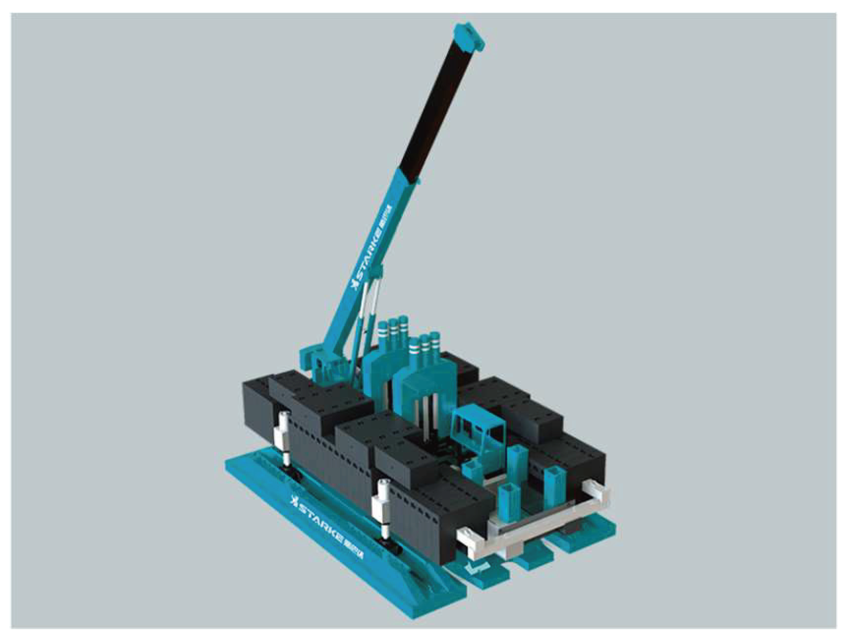
With the current requirements of green development and energy conservation and emission reduction, lightweight has become the new trend of manufacturing industry development. In the manufacturing industry, product "weight loss" has become the priority of product design, research and development. While ensuring the performance the product should have, its lightweight design not only enables the development of high-efficiency product quality and material savings concepts, but also helps enhance the key competitive advantage of the enterprise. A static pile driver is a piling machine that uses static pressure to press piles into various substrates, thus implementing a foundation for construction implementation [
1], as shown in
Figure 1.
The large-body skeleton structure is a key component of the hydraulic static pile driver. Specifically, it is the main load-bearing part of the pile driver. Except for the lower support structure and walking mechanism of the pile driver, the weight of the rest of the pile driver is supported by the large body of the pile driver, so that the pile driver and the crane can work correctly. In this way, it plays a role in the entire structure of the pile driver. With a large body structure, the motion of the walking and traversing mechanisms will drive the upper parts that cannot move together. Therefore, the design of the large-body skeleton structure plays a crucial role in the working performance and operation of the pile driver. Optimal design methods based on sensitivity analysis have found applications in numerous fields [
2,
3], such as automotive, aerospace design, and agricultural machinery. However, for the application of pile machinery, especially the metal structure of pile machinery, there is extremely minor. Therefore, in order to reduce the production cost, this paper optimizes the large-body structure of the pile press based on sensitivity analysis, and reduces the weight of the large-body skeleton structure as much as possible while satisfying the strength and stiffness constraints [
4].
2. Body Model Structure and Analysis
2.1. Finite element model
This paper takes the large body skeleton structure of hydraulic static pile driver model YZY400 as the research object. The finite element model of the large body structure of the pile driver is established and studied by using ANSYS APDL finite element software. The performance parameters of the whole machine of the pile driver are shown in
Table 1.
The large body structure of this model of static pile driver is all welded by steel plates and it is a complex space box system structure. In order to ensure that the finite element analysis is carried out properly and effectively, the original model is simplified appropriately. Members without load-bearing effects were removed, details such as unnecessary holes and rounded corners were simplified, and legs attached to the bulk structure were simplified. According to the characteristics of the large body structure itself, in order to facilitate the parametric optimization analysis of the large body structure, this paper uses ANSYS APDL modeling software for the parametric modeling of the large body structure. Since the bulk structure belongs to a large thin plate structure with a large difference between the thickness and the rest of the dimensions, the plate and shell units are chosen to simulate actual steel plates when modeling. The specific type is chosen from the shell 63 in APDL [
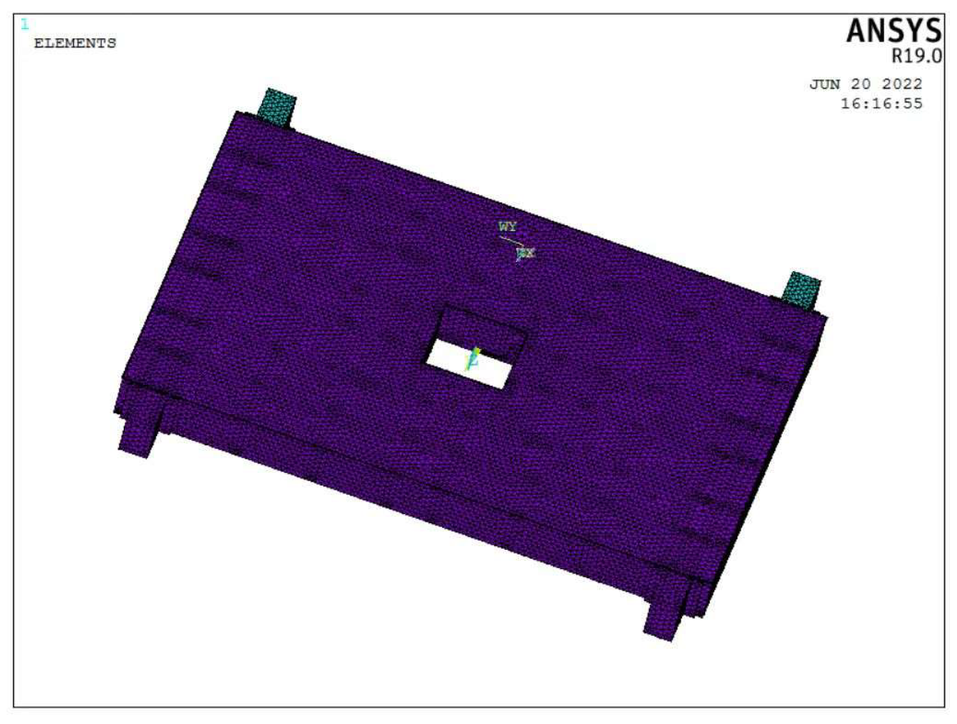
5], and the free triangles are used in the face meshing of the large-body skeleton model to obtain the large-body structure finite element model. As shown in
Figure 2, the model has 19, 728 nodes and 312, 110 cells.
After the establishment of the finite element model of the large body structure, the boundary conditions are applied to the model and the static analysis is carried out based on the loads that the large body skeleton is subjected to in the actual work.
2.2. Static analysis
2.2.1. Typical working condition selection
In addition, a hydraulic oil tank and cab, used to power the pile driver for pile extraction and pile pressing, were also mounted on the large body skeleton. The static pile press operates on the pile by means of a pile-pressing mechanism, powered by a hydraulic cylinder in the chassis platform, to enable both pile-pressing and pile-pulling actions. The static pile driver operates on the pile through a pile-pressing mechanism, powered by hydraulic cylinders in the chassis platform, to enable a pile-pressing and pile-pulling action. The pile-pressing mechanism is connected to the large body in the upper part of the massive body skeleton structure. The entire pile driver travels and moves through a travel mechanism and a traverse mechanism in the lower part of the large body platform. The outriggers were bolted to the bulkhead structure, and the outriggers had hydraulic cylinders attached to the long-boat by hinges. The ball head of the ball hinge is attached to the slewing mechanism and the short boat. The large-body platform structure will link the static pile drivers into a single unit that will directly bear the reaction force when the pile is pressed. The maximum deformation of the bulk structure occurs when the static pile driver implements the pile-pressing action. In this paper, we present a hydrostatic analysis of the pile-pressing operation and its hydrostatic properties under the most dangerous operating conditions [
6].
2.2.2. Analysis of stress results in typical working conditions
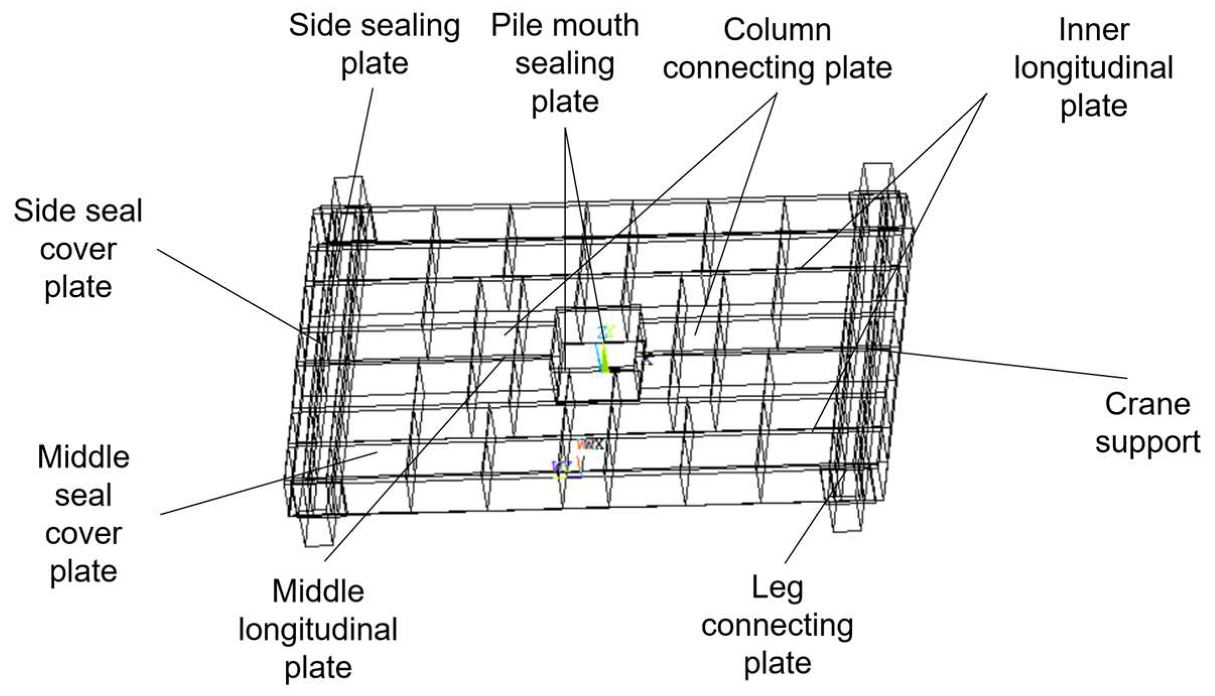
The maximum pile-up force of the pile-up driver is 400 t. The combined effect of the maximum pile-up reaction force and the gravity of the pile-up table itself has an upward effect on the pile-up driver's bulk structure. The longitudinal meander mechanism supports the entire structure, and the combined force acts on the connecting surfaces of the cylinder and column in the form of a uniform load q. The calculated load q is 3.061 Mpa, and a diagram of the bulk structure is shown in
Figure 3.
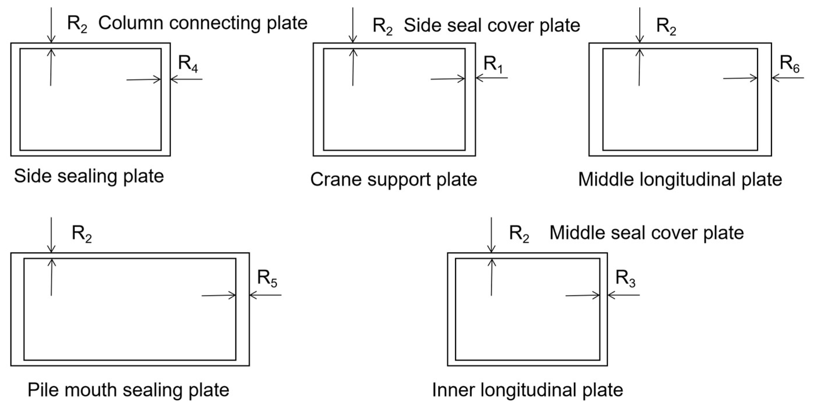
In the finite element, the transmission of force is carried out with the help of nodes, so the load can be applied either centrally on the nodes or uniformly on the surface. This calculation applies the load q on the connection surface of the column with the uniform load applied, where the large body structure cross-sectional dimension parameters are shown in
Figure 4.
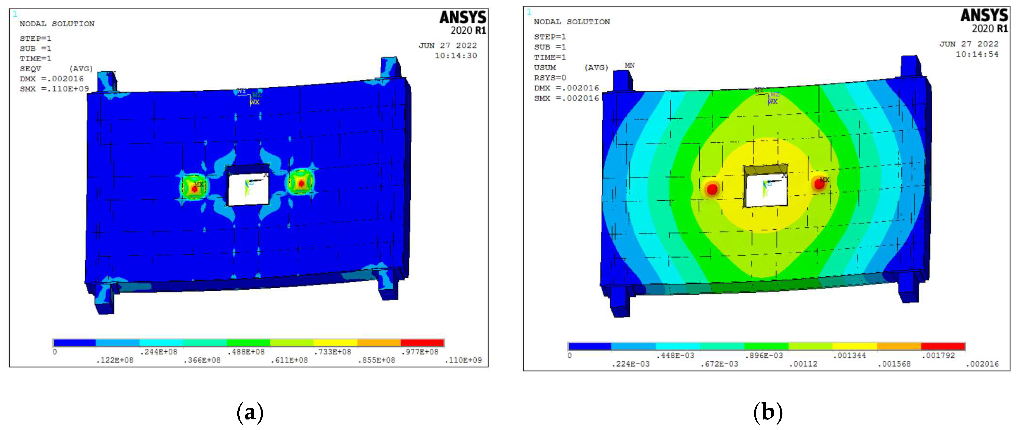
Appling full constraints for the four legs connected to the large body during solving for static analysis. The structure was analyzed in ANSYS APDL, and the stress cloud and displacement cloud of the large body skeleton under the compression pile condition were obtained as shown in
Figure 5.
From
Figure 5 (a), it can be seen that the maximum stress of the big body skeleton is 110 MPa. The maximum stress appears at the connection of the legs of the big body structure, which is consistent with the actual working condition. According to the crane Chinese standard GBT3811-2008, taking 1.34 as the safety factor, the allowable stress of the material is 175MPa, which meets the design requirements.
As can be seen from
Figure 5 (b), the maximum displacement is 2.01 mm under the pile pressing condition, which meets the requirements. The maximum deformation near the hydraulic cylinder cover plate is also in line with the actual situation.
4. Theoretical foundations of sensitivity analysis
We refer to the gradient of variation of the structural or product performance values with respect to the design variables as sensitivity. When analyzing the structural stiffness, the gradient of the variation of the stiffness to the value of the thickness d of each plate of the large body is the sensitivity [
7]. Mathematically speaking, if F(d) is derivable, then the first-order sensitivity S of this function is:
Where: is the performance value of the large-body structure. is the design variable of the large-body structure.
Finite element analysis theory emphasizes that for general structural static finite element analysis has:
Where: denotes the external load vector of the structure. is the displacement vector of the structure. is the total stiffness matrix of the finite element model; n is the degrees of freedom of the structure.
is the partial derivative of
with respect to the design variables d.
is the partial derivative of
with respect to the design variables d.
is the derivative matrix of
to d, and the derivative of (2) with respect to d is obtained:
If the vector
is equal to 0, then there is :
Where:
is the inverse matrix of the total stiffness matrix of the structural finite element model. The total stiffness matrix of the structural finite element model is obtained after summing the corresponding matrices of each cell, which is:
Where: e is the cell number;
is the expanded cell stiffness matrix. The derivative of the formula of (6) to d is obtained:
Equation (5) can be replaced by :
Where:
is the cell stiffness derivative matrix without order expansion, ne is the cell degrees of freedom.
is the component of the corresponding unit e in
, which is the vector of the individual unit displacements. Then, the formula of (8) is required to calculate the sensitivity of the structural displacement vector
to the design variable d. In the optimization analysis of the large body skeleton structure, the large body finite element model is composed of plate and shell units, so the unit stiffness matrix before the expansion of the plate and shell units is:
Where: E is the modulus of elasticity of the material; d is the real constant of the plate and shell unit, which is the thickness of the plate.
and
are the membrane stiffness and bending stiffness of the plate in the stiffness of shell unit. While the coordinates of each node in the cell of e are related to
and
, which are not related to the modulus of elasticity E and the thickness of the plate d, and as we know :
Therefore, the value of can be obtained by performing only one more calculation of the stiffness matrix of each cell.
5. Optimized design of structures
5.1. Sensitivity analysis
The mass of the large body skeleton of a pile-driver is related to the mass of each of the thin plates that make up its structure. For thin slabs, the dimensional properties that affect their mass are dominated by the thickness of the slabs, so the sensitivity analysis of the bulk skeleton structure to the thickness of each slab is mainly considered. The results of the sensitivity calculation are typically derived from the DOE analysis [
8]. The experimental factors that have a large effect on the performance of the skeleton structure can be obtained by screening from several design variables also known as experimental factors. The sensitivity calculation method can be used to achieve a reasonable allocation of materials, so as to improve the light weight of the large body structure. The influence of the change of the design parameters of the large body skeleton structure on the performance of the large body structure and its extent are quantitatively studied. Then the parameters that are most sensitive to the response of the big body structure performance in the optimization design process will be screened out. In turn, the optimal range of variables for optimal design is obtained, and the optimal design variables are further extracted. It is discussed that the sensitivity analysis of the large body structure of the pile driver in the most dangerous working condition involves the large body strength, stiffness and total mass of the large body structure of the pile driver. Considering that the large body structural members are all thin steel plates, the thickness of large body plates is selected as the structural design variable. Sensitivity analysis is performed for the maximum stress at the nodes of the big body structure, the maximum displacement, and the mass of the big body skeleton of the pile driver.
DOE is computed analytically using an iterative approach, and for experiments, the maximum and minimum values of the design variables, that is, the upper and lower limits, must be determined. There are numerous commonly used experimental design methods, such as Central composite [
9,
10,
11], Fractional Factorial, Full Factorial, Latin Hypercube, Orthogonal Array, Sobol Sequence, etc. After the analysis, the Latin square experimental method was considered for the experimental design. The results of the sensitivity of the thickness of the steel plate of the large body structure to the mass, displacement and structural stress were obtained after the arithmetic analysis, as shown in
Table 2,
Table 3 and
Table 4.
Combined with the results of the sensitivity analysis of the design parameters, the parameters that have a greater impact on weight reduction but have minor impact on the stiffness and strength of the large body structure are selected as design variables. Therefore, R1, R3~R6, a total of five parameters are selected as design variables [
12,
13,
14].
5.2. Constructing optimal design model
1) Design variables: The large body skeleton of the pile driver is mainly made of thin steel plates welded together, and the steel plate thickness R is chosen as the design variable.
2) Constraints: The strength and stiffness of the large body skeleton are the constraints.
3) Objective function: The large body skeleton mass M is minimized as the objective.
An optimization mathematical model is developed as follows:
Where: is the thickness of the plate, n is the number of variables, is the maximum stress obtained by calculation; is the maximum deflection obtained by calculation, and M is the mass of the large body structure.
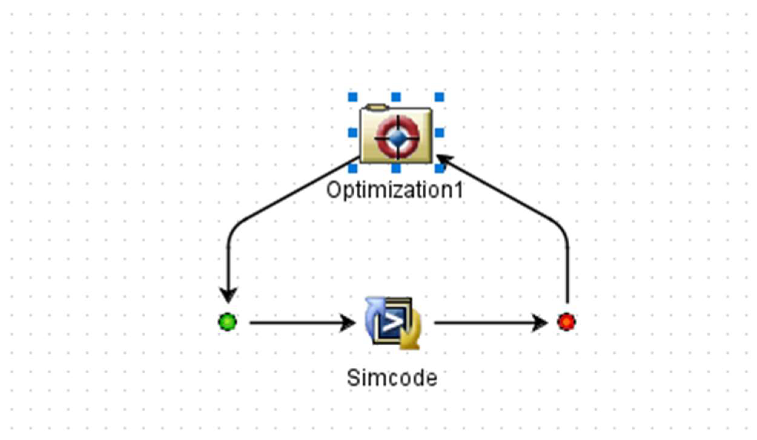
ISIGHT software is a "software robot" that can quickly integrate and couple various software by building blocks. It includes specialized integration components for various CAE software such as Abaqus, CATIA, SolidWorks, ANSYS, MATLAB, etc. ISIGHT can also integrate various software that cannot be used directly through the common integration component simcode for efficient and quick simulation. By integrating ANSYS APDL parametric language design programs, Windows batch files and output files into ISIGHT, calls to ANSYS can be implemented. In this paper, a workflow consisting of an optimization calculation component and a call to the simcode component of the ANSYS APDL software is used to perform the optimization model calculation. As shown in
Figure 6, a circular workflow of simcode and optimization is created in ISIGHT [
15,
16].
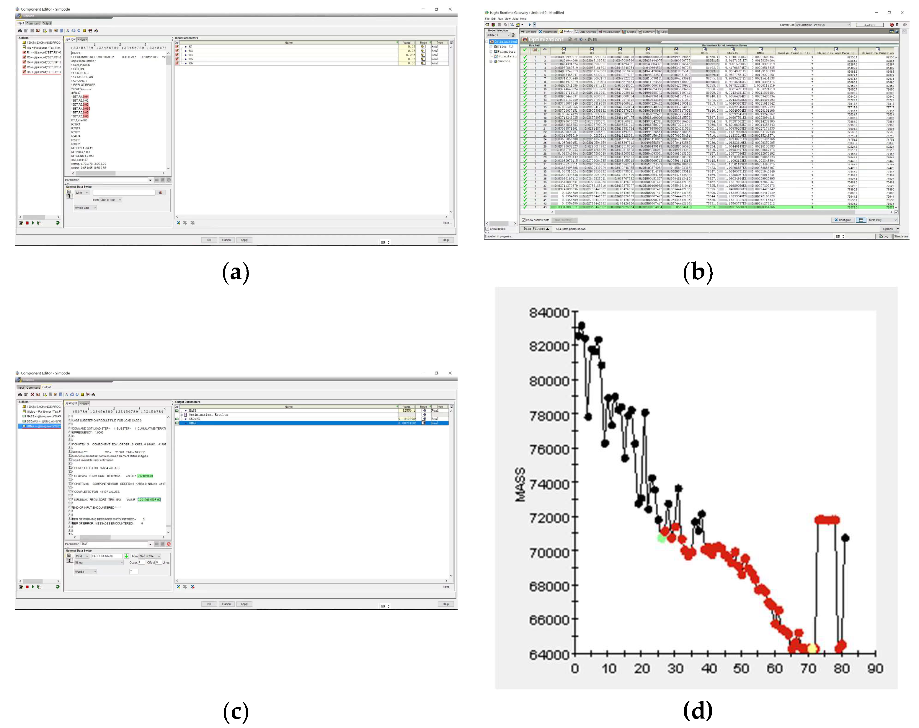
The input variables and output variables are set in simcode as shown in
Figure 7 (a,c), and the pointer optimization algorithm is selected to perform the calculation process as shown in
Figure 7 (b), and the mass distribution of the large body structure is obtained as shown in
Figure 7 (d).
6. Results
The thicknesses of the design variables before and after optimization and the rounded thickness after optimization are shown in
Table 5, and the comparison results of the maximum stress and maximum displacement of the structure before and after optimization are shown in
Table 6.
As can be seen from
Table 6, the maximum stress value of the large-body skeleton is 110 MPa under pile compression before optimization and 162 MPa after optimization. With a safety factor of 1.34 and a maximum safe stress value of 175 MPa, the optimized stress value still has a large margin and thus meets the design requirements. Although the maximum displacement is increased to 2.96 mm before and after optimization, compared to 1.22 mm before optimization, there is still a large excess for the stiffness condition for large body structures. It can be seen that the optimized structure satisfies the design requirements.
7. Conclusions
In this paper, the typical working conditions of a pile press are used as an example to study how to improve the light weight of the large body structure of a static pile press. We first develop a finite element model of the large body structure of a static pile driver. The strength and stiffness of the large body of the pile driver were verified through finite element analysis to meet the design requirements. On this basis, the structure optimization based on sensitivity analysis is carried out. A mathematical analytical model of the optimization was constructed and the results of the optimization showed that the strength and stiffness of the optimized large-body structure of the hydrostatic pile driver are within reasonable limits. Therefore, the hydrostatic pile driver has great safety and reliability, which can completely ensure the safety of the pile driver during the working process. Compared to the mass of the pre-optimized bulk structure, which was 82,556.1 Kg, the optimized bulk structure has a mass of 64,282.6 Kg, a 22.1% reduction in mass. It is highly cost-effective to produce and has some guiding implications for future lightweight designs of piling machinery.
Author Contributions
Conceptualization, J.W.; methodology, Y.Y.; software, Y.Y.; validation, Y.Y.; formal analysis, J.W.; investigation, J.H.; resources, J.H.; data curation, J.H.; writing—original draft preparation, Y.Y.; writing—review and editing, Y.Y.; visualization, Y.Y.; supervision, J.W.; project administration, J.W.; funding acquisition, J.W. All authors have read and agreed to the published version of the manuscript.
Funding
This research was supported by key scientific research projects of colleges and universities in Henan Province (Grant No.17A460020).
Data Availability Statement
Not applicable.
Conflicts of Interest
The authors decare no conflict of interest.
References
- Yu W, Xiongqing Y. Expression, uncertainty analysis and solution strategy of robust optimization [J] China Manufacturing Informatization, 2008 (03): 49-54.
- Weiya J, Zijian M, Shuiqing Z, et al. Research on Multi-Optimal Project of Outlet Guide Vanes of Nuclear Grade Axial Flow Fan Based on Sensitivity Analysis[J]. Applied Sciences, 2022,12(6). [CrossRef]
- Fu C L, Bai Y C, Lin C, et al. Design optimization of a newly developed aluminum-steel multi-material electric bus body structure[J]. Structural and Multidisciplinary Optimization, 2019,60(5). [CrossRef]
- Chen W, Zuo W. Component sensitivity analysis of conceptual vehicle body for lightweight design under static and dynamic stiffness demands[J]. Int. J. of Vehicle Design, 2014,66(2). [CrossRef]
- Fangfang H, Tuwei L, Dongdong W, etc. Robust optimization design of crane girder structure based on response surface model [J] Lifting and transportation machinery, 2020 (24): 51-56.
- Youxin L, Xiaoyi C, Jirong Y, etc. High-dimensional multi-objective grey robust optimization design and its Matlab implementation [J] Journal of Agricultural Machinery, 2008 (08): 157-160.
- Bin S, Changfeng W, Songkui Y, etc. Optimization design of steel-aluminum hybrid bus frame based on sensitivity analysis [J] Bus Technology and Research, 2021,43 (03): 29-32.
- Jing T, Chao S, Fuyun L, etc. Research on lightweight method of commercial vehicle cab based on structural parameter sensitivity analysis [J] Mechanical Design, 2021,38 (11): 97-101.
- Zuo W, Yu J, Saitou K. Stress sensitivity analysis and optimization of automobile body frame consisting of rectangular tubes[J]. International Journal of Automotive Technology, 2016,17(5). [CrossRef]
- Xufei W, Denning J, Fei T, etc. Lightweight design of bus frame based on sensitivity analysis [J] Modern Manufacturing Engineering, 2021 (09): 52-57.
- Fengfeng W, Guolai Y, Jianli G, et al. Lightweight design of a certain mortar base plate based on sensitivity analysis[J]. Journal of the Brazilian Society of Mechanical Sciences and Engineering, 2021,43(3). [CrossRef]
- Xinhao Z, Yanxiong L, Lin H, et al. Structural Analysis and Size Optimization of a Fine-Blanking Press Frame Based on Sensitivity Analysis[J]. STROJNISKI VESTNIK-JOURNAL OF MECHANICAL ENGINEERING, 2020,66(6). [CrossRef]
- Jiwei Q, Ruijun Z, Xiaowei W. Reliability robust optimization design based on sensitivity additional objective function [J] Mechanical strength, 2014,36 (01): 45-50.
- Wei L. Research on multidisciplinary robust design optimization method considering parameter and model uncertainties [D] Huazhong University of Science and Technology, 2020.
- Lu W. Robust optimization design based on agent model and its improvement [D] Northwest University of Technology, 2018.
- Zhendong Zh. Research on key technologies of robust equilibrium optimization design of mechanical structure performance based on interval [D] Zhejiang University, 2018.
|
Disclaimer/Publisher’s Note: The statements, opinions and data contained in all publications are solely those of the individual author(s) and contributor(s) and not of MDPI and/or the editor(s). MDPI and/or the editor(s) disclaim responsibility for any injury to people or property resulting from any ideas, methods, instructions or products referred to in the content. |
© 2023 by the authors. Licensee MDPI, Basel, Switzerland. This article is an open access article distributed under the terms and conditions of the Creative Commons Attribution (CC BY) license (http://creativecommons.org/licenses/by/4.0/).
