1. Introduction
Due to impractical, high cost, limited experimental facilities and other reasons, it was often not feasible to conduct full-size experimental studies on impacted structures [
1]. In this case, it was very attractive to develop the scaling methods using scaled model instead of full-size prototype in experimental research. The method relating physical quantities between the scaled model and the full-size prototype was called to be similarity laws [
1,
2], which was usually based on the similar premise of geometry, materials and loads. With the development of impact dynamics, scaled models had been extensively applied in many fields of structural impact, no matter for the isotropic solid materials or advanced anisotropic composite materials [
3,
4]. In contrast, the similarity laws of anisotropic materials are more complicated because the material parameters are closely related to directivity of structural geometry space.
The traditional similarity laws were well-known and based on a basic geometric scaling factor relating any spatial directions and material parameters [
1,
2]. The geometric scaling factor was defined as
, where
was the characteristic length of the structure; the subscripts
and
represented scaled model and full-size prototype, respectively. In addition, it was used not only for the scaling test of isotropic materials [
1,
2], but also for the scaling test of more complex anisotropic composites [
5,
6,
7,
8]. However, the traditional similarity laws do not allow the distortion problem in which the input parameters such as materials and geometry cannot fully satisfy the requirements of the scaling relations. The material distortion is usually caused by the material strain rate effects, the fracture and the use of different materials for scaled model and full-size prototype, while the geometric distortion is usually caused by different geometric scaling factors in different spatial directions [
1]. Within a few decades of the initial development of the similarity laws of structural impact, the material and geometric distortions have been considered difficult to overcome whether for both isotropic [
1] or anisotropic materials [
9].
Because of the widespread existence of the material and geometric distortion, the application of traditional similarity laws has been seriously limited [
10,
11,
12,
13]. For example, different materials must be used in a scaled model because the completely same materials as the prototype cannot be found. Another example was that the geometry of the structures cannot be manufactured efficiently, especially in the thickness directions of scaled models. To solve the difficulty of distortion of metal materials, in the last two decades, some researchers extended the traditional similarity laws by using a new scaling relation with the basic scaling factor of length, density and velocity [
13,
14,
15,
16,
17,
18] and reasonably designing the optimal similitude materials [
19,
20]. On this basis, the initial conditions (impact velocity and density/mass) of the scaled model were corrected to compensate for distortion of different materials with strain hardening, strain-rate sensitive and thermal effects. Some studies further considered the influence of geometric distortion of thickness and obtained the simple scaling relations by empirical iterate methods [
21,
22,
23] and by dimensionless analysis method for impacted simple beam and plate [
24]. Since the defects of traditional similarity laws were overcome fundamentally, these works established a new scaling system and had gradually become widely used in the last twenty years [
20]. However, the new similarity laws have not been applied to study the impact problem of anisotropic materials due to its complexity.
With the development of science and technology, anisotropic materials represented by composite materials are widely used in aircraft structures and other engineering fields [
25]. The essential difficulty of anisotropic material similarity is that the material parameters were closely related to the different spatial orientations. In order to consider directivity of space, Wang et al. [
26] proposed a directional similarity framework based on the oriented dimensional analysis method and the impacted thin-plate model. Since three directions of space were introduced into the bases of dimensional analysis, the similarity of geometric distortion including all stress, strain and displacement components were expressed systematically. However, due to the limitation of the research subjects of the isotropic plastic materials, this works only considered the thickness distortion and ignored the inherent capability of width distortion. Based on the framework, Li et al. [
27] further expanded the application scope to obtain the similarity of isotropic elastic-plastic coupling situation. Meanwhile, Davey et al. [
28] developed a scaling system with width and thickness distortion for isotropic and anisotropic elastic materials based on equation analysis method. When dynamic loading involved a dominant component of velocity/displacement, different anisotropic and isotropic elastic materials can obtain approximate similarity. Nevertheless, this work did not carry out in-depth and systematic analysis on the anisotropic material and geometrical distortion, and only used two stiffness coefficients in the x direction and the x-y plane direction as the dominant material parameters to obtain incomplete similarity of some physical quantities.
The main defect of the previous similarity laws to solve distortion problem was that they only focused on isotropic materials and rarely studied from the perspective of anisotropic materials. The essential reason was that, in the dimension and similarity analysis, most of them did not take into account the directivity of structural characteristic length and material parameters. In order to study the anisotropic similarity laws with material and geometric distortion more systematically and deeply, in this paper, a distorted similarity law framework of anisotropic elasticity was proposed by extending the directional similarity framework proposed in Ref. [
26]. Compared with the previous other similarity laws, the new similarity laws were based on dimensional analysis and the classical plate theory, so it was very simple and understandable. More importantly, by using three spatial characteristic lengths instead of the traditional one in dimensional analysis of anisotropic elastic materials, the directivity of physical quantities and structural geometric characteristics were systematically introduced into dimensionless numbers and scaling relations. The applicability and mechanism of the material and geometric distortion of anisotropic elasticity were also deeply explored.
In what follows,
Section 2 introduces our newly proposed scaling procedure for material and geometric distortion of anisotropic elasticity.
Section 3 investigates the numerical models of a clamped square plate of anisotropic elasticity subjected to dynamic pressure pulse.
Section 4 discusses in depth the similarity mechanism caused by material parameters.
Section 5 summarizes this work.
2. Distorted scaling procedure of anisotropic elasticity
2.1. The main defects of the previous similarity laws
In the past, the similarity laws to solve distortion problem mainly focused on the plastic materials with strain hardening, strain rate and temperature effects, but rarely dealt with the anisotropic elastic problem under impact. When scaled model was used for different anisotropic elastic materials and the geometric distorted structures, the previous similarity methods were broken because the anisotropic elastic parameters were closely related to the spatial direction. The dissimilar phenomena are briefly analyzed as follows.
Considering that the elastic modulus
and the Poisson’s ratio
are the dominant similar parameters for anisotropic materials, their general dimensions are expressed as
and
, where the notation ‘
’ represents dimension of physical quantity; the symbols
,
and
represent dimensions of length, mass, and time, respectively; and
. The well-known Buckingham theorem [
1] states that physical quantities of a mechanical model can be reduced to dimensionless numbers to simplify causal relationship between them. When the density
, the characteristic length
and the velocity
are used as bases of dimensional analysis [
18], the dimensionless numbers
and
can be obtained. The number
, often termed as the Cauchy number [
29], is a well-known important dimensionless number and control the similarity of elasticity, while the number
is a natural dimensionless number. For scaled model and prototype, the dimensionless equality
and
can be translated into the scaling relations
and
, respectively. The two scaling relations indicate that the necessary condition of similarity of anisotropic elastic materials is that the material parameters in each direction satisfy the same scaling factor. Therefore, when the material used in the scaled model is different from that of the prototype, the similarity condition will be broken. In addition, since the scaling relation of the Poisson’s ratio in each direction is equal to 1, it can be inferred that another necessary condition of similarity is that the scaled model is geometrically similar to the full-size prototype. Thus, when the geometric characteristics of the structure in different directions are scaled according to different scaling factors, the similarity condition will also be broken.
The above analysis shows that similarity laws of the anisotropic material and geometrical distortion cannot be derived when the general dimensional analysis is used. In order to overcome this difficulty essentially, we further consider the directional similarity law framework.
2.2. Review of the directional framework of similarity laws
Different from the general dimensional analysis, which used one scalar length dimension
for all the structural characteristic length
, the directional framework of similarity laws used the oriented length dimensions
,
and
[
30,
31] for three spatial characteristic lengths
,
and
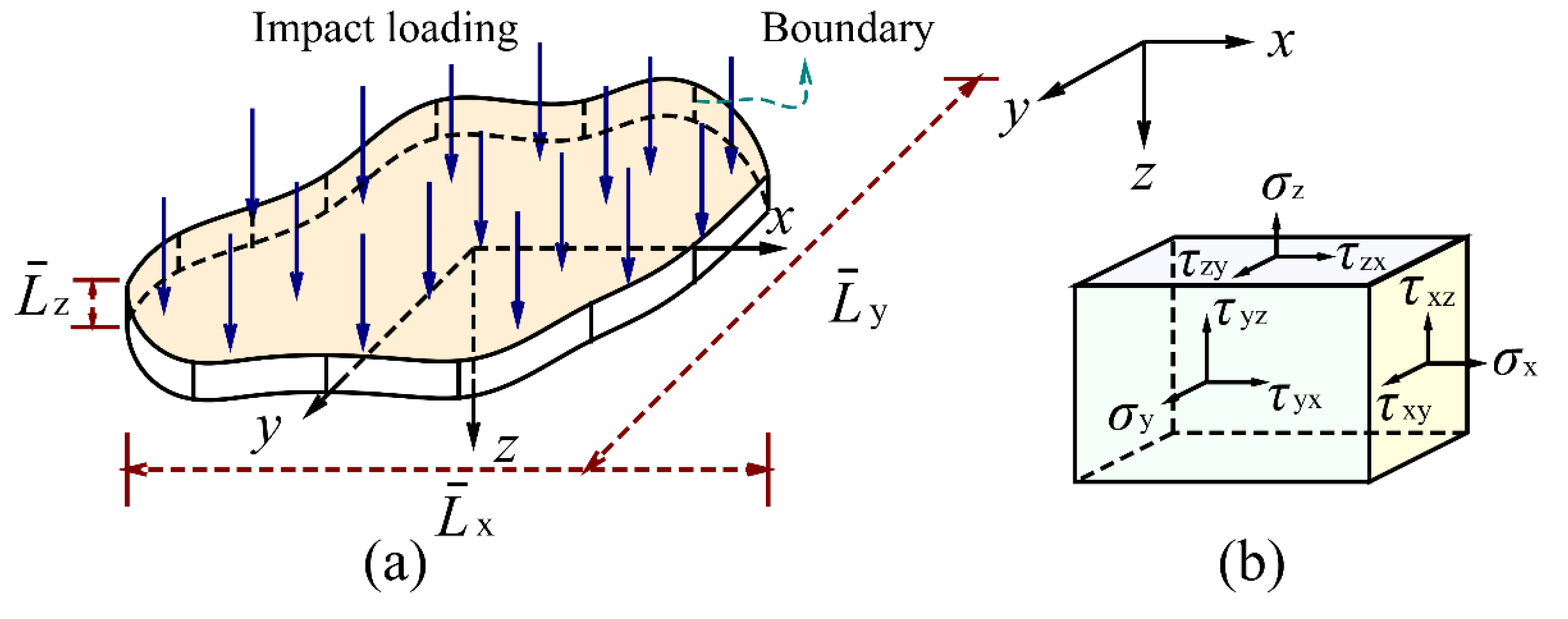
, respectively. The advantage of oriented dimension was that it introduced spatial directionality into dimensional analysis through different characteristic lengths. To determine the oriented dimensions of structural impact, a mechanical model of a thin-plate impact problem was further used, as shown in
Figure 1. The main reason for using the thin-plate impact model was that its loads and displacements were dominated by transverse components, thus reducing the complexity of oriented dimensional analysis. For the classical plate theory, the strain components [
31] were simplified as
,
,
,
,
and
, where
,
and
represented the displacement components of neutral plane elements on the
-axis, the
-axis and the
-axis, respectively;
represented the distance to the neutral plane. The whole displacement fields were expressed as
,
and
, where the second term to the right of
and
represented the displacement caused by the deflection [
31]. Based on this impact model and the oriented dimensional method, the directional similarity framework including oriented dimension, directional dimensionless number and directional scaling relations were derived as follows [
26]:
When the oriented dimensional analysis method was used, the oriented dimensions of main physical quantities in the thin-plate impact problem can be obtained. For example, based on the equation of motion,
, the oriented analysis was given as
, which can derived the oriented dimension
,
,
,
,
and
for the stress components
,
,
,
,
and
, respectively. Similarly, based on the oriented analysis of the strain components, the displacement fields of the classical plate theory and the impact loads, the oriented dimensions of 6 strain components, 3 displacement components, impact mass and pulse pressure can also be derived. The detailed derivation can be found in Ref. [
26]. The main physical quantities and their corresponding oriented dimensions in the thin-plate impact problem are listed in
Table 1. Compared with the scalar dimensions such as
and
, the oriented dimensions can effectively distinguish physical quantities in different directions, especially originally dimensionless strains. In addition, Ref. [
26] also defined the oriented dimensions of equivalent stress, equivalent strain and plastic strain components. Since the study object in this paper is anisotropic elasticity, the oriented expressions involving plasticity are not listed in here and later.
When the density
, the characteristic length
,
,
and the velocity
are selected as bases of dimensional analysis, according to the Buckingham theorem [
1], 23 physical quantities in
Table 1 can be casted as the following 18 dimensionless numbers:
It should be noted that Eq. (1a-f), Eq. (2a-f) and Eq. (3a-c) can be expressed as the three tensor forms
,
and
(no sum on
and
), where
. Apparently, the stress, strain and displacement components were all related to the structural characteristic length of three spatial directions in the dimensionless relationship, and had the characteristic form of geometric power law of
. In contrast, these dimensionless numbers in scalar dimensional analysis [
18] were expressed as
,
and
, which had no the characteristic of geometric power law.
Based on the above dimensionless numbers, the scaling relations of physical quantities were listed in
Table 2. Obviously, these similarity relations were based on expression of the five basic factors
,
,
,
and
, which behaved quite differently from the previous similitude laws using only a single geometric scaling factor
(i.e.,
). Thus, when any two of
,
and
was not equal, the similarity laws were geometrically distorted.
The derivation above formed the basic framework of the directional similarity laws. Since it was based on the oriented-density-length-velocity bases of dimensional analysis, the above similarity laws were termed as the ODLV system.
2.3. Directional dimensionless number and scaling relations of anisotropic elasticity
In this section, we further extend the directional framework of ODLV to the impact problem when thin-plate is made of anisotropic elastic materials.
In order to derive the directional similarity laws of anisotropic elastic materials, the Hooke’s law of orthotropic anisotropy [
32],
are studied, where
is Poisson’s ratio;
and
specifically refer to Young’s modulus and shear modulus, respectively. According to symmetry of flexibility matrix, the material parameters have the reciprocal relations
,
and
[
32]. Therefore, among these material parameters, only nine are independent of each other for anisotropic materials, namely,
,
,
,
,
,
,
,
and
.
The oriented dimensional analysis of Eq. (5a-f) can obtain the following relation:
When the dimensions of stress and strain components in
Table 1 are substituted into Eq. (6a-i), the oriented dimensions of elastic parameters can be derived, which are listed in
Table 3. It is obvious that when the method of oriented dimensional analysis is used, the elastic parameters in different directions exhibit different dimensions, and the Poisson’s ratio is no longer a dimensionless quantity.
When the bases of
,
,
,
and
are used, according to the Buckingham Π theorem, the elastic parameters in
Table 3 can be deduced as the following dimensionless numbers:
In the derivation above, the x-axis and y-axis directions of the characteristic length are consistent with the two main directions 11 and 22 of the material, respectively. Therefore, for anisotropic materials with ply angle, the selection of characteristic lengths is determined by the directions of materials rather than usual geometrical characteristics. In addition, Eqs. (7a-f) and (8a-c) can be expressed as the tensor forms and (no sum on and ), respectively. Compared with the numbers and in scalar form, the new proposed dimensionless numbers here further express the geometrical characteristics of the structure by the geometric power term and .
When the directional dimensionless numbers of the elastic parameters are used for scaled model and full-size prototype, they can be further transformed into the scaling relations about materials. For the nine physical quantities in
Table 3, their scaling relations are listed
Table 4. The scaling relations form a foundation of distortion scaling for anisotropic elasticity. Compared with the previous scaling relations
and
in scalar dimensional analysis, the elastic parameters in different directions are closely related to the scaling of the characteristic length in the corresponding directions. When a scaled impact test is performed, the geometry, loads and material parameters of scaled model need to satisfy the relations in
Table 2 and
Table 4. After the test is completed, the behavior of the full-size prototype can be predicted from scaled model by using these relations.
2.4. Correction methods for geometric and material distortion of anisotropic elasticity
When the relations in
Table 4 are used to perform the scaling test of impact problem, the nine independent material parameters
,
,
,
,
,
,
,
and
need to be satisfied. It is easy to find that these parameters are not independent of each other at scaling, and they have the following equation
In practice, Eq. (9) is fully satisfied when the scaled model and the full-size prototype use exactly the same anisotropic materials. In this case, and . Therefore, for the same anisotropic material, the impact behavior follows the traditional similarity laws and cannot be allowed to scaling of material and geometric distortion.
In what follows, in order to further consider the material and geometric distortion using different anisotropic parameters, the incomplete scaling techniques that select some physical quantities as dominant parameters are used to break the similarity constraint of Eq. (9).
For the thin-plate impact problem, when the deformation conforms to the geometric nonlinearity assumption of small strains under moderate rotation of
, the transverse strain and stress components can be approximately ignored [
26]. Then, the Hooke’s law of orthotropic anisotropy in Eq. (5) can be reduced to the following form
Obviously, only four independent material parameters
,
,
and
need to be considered in the scaling relations. When combined with
Table 4, the following relation can be found
In this equation, the similarity of the material parameters is only related to and , not to . Therefore, the geometric thickness of the structure can be arbitrarily distorted. Nevertheless, it is still difficult to satisfy this equation when different anisotropic materials are used at scaling.
In order to further relax the restriction of distortion, the dimensionless number of dominant material parameters needs to be further simplified. Firstly,
and
are assumed to be the dominant material parameters and
. Then, Eq. (11) can be reduced as
The above equation shows that the geometric scaling ratio of the two in-plane directions is equal to a quarter power of the scaling ratio of the corresponding material parameters. Therefore, when the scaled model is not the same as the full-size prototype material, the geometric thickness of the structure needs to be corrected to compensate for the material difference.
In addition, another main distortion method can also be formed when
and
are assumed as dominant parameters. In this case, Eq. (11) can be reduced as
Compared with the relation in Eq. (12), the ratio of material parameters in Eq. (13) is equal to the ratio of width to length to the 1/2 power. Therefore, different scaling schemes have different width distortion capabilities.
Furthermore, in Eq. (11),
is also an incomplete scaling scheme. However, since the Poisson’s ratio is much less important than the effect of elastic modulus on anisotropic thin-plate, this scaling scheme is not desirable, which will be further discussed in depth in
Section 4.
From the above analysis, it can be seen that for the case of that the scaled model using the same material as the full-size prototype, only geometric thickness distortion is allowed. For the case of the different materials, except for geometric thickness distortion, the width of the scaled model must be corrected according to Eq. (12) or Eq. (13). The geometric thickness can be corrected to any value without being affected by material parameters, while the correction of geometric width is restricted by the difference of material parameters in the x-y plane. For convenience, the scaling techniques of distortion that fully satisfies Eq. (11), Eq. (12) and Eq. (13) are called the techniques M0, MⅠ and MⅡ, respectively, which are listed in
Table 5. In summary, the above derivation establishes the necessary conditions for the similarity of anisotropic elastic materials from the point of view of distortion.
Finally, in addition to the geometry and material needs to meet the distorted scaling requirements, the impact loads also need to be scaled reasonably. According to the scaling relation
in
Table 2, the correction of impact velocity can be derived as
Equation (14) shows that by correcting the impact velocity, the distortion of geometric thickness and the distortion of materials in density and elasticity modulus can be further compensated. Since is proportional to , more input energy for scaled model with the case of is needed to offset the resistance of the structure to deformation caused by the increase in thickness.
4. Discussion
When using the distortion methods of geometric thickness and width, the theoretical basis for the establishment of incomplete similarity is the assumption of the relative importance of material parameters. Therefore, it is necessary to discuss the source of similarity error and the importance of these material parameters in depth and to analyze the applicability of incomplete similarity.
(1) The Poisson’s ratio has relatively less effect for similarity.
In the derivation of the incomplete similarity used MⅠ and MⅡ, the Poisson’s ratio is ignored. Based on the Hooke’s law of Eq. (10a) and (10b), the influence of the simplification can be discussed by the following two aspects.
Firstly, for the impacted square plate in
Section 3.1, the influence of the Poisson’s ratio
on the strain
and the strain
is smaller than the influence of
and
, respectively. To describe the relative importance of the Poisson’s ratio, the dimensionless ratios
and
are defined from Eq. (10a) and (10b), respectively. Obviously, the greater the value of
and
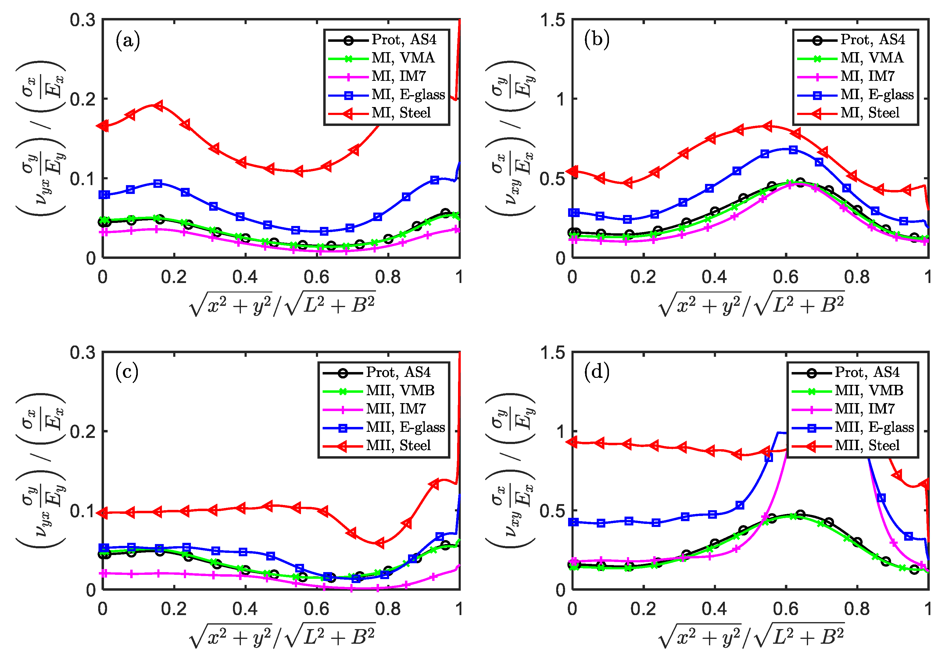
, the greater the contribution of Poisson’s ratio on the normal strains. Then, for scaled models used the scaling techniques MⅠ and MⅡ,
and
in the spatial fields are plotted in
Figure 7. Since the y-coordinate of the curve is less than 1, the contribution of
for
and the contribution of
for
are significantly less than those of
and
, respectively. Therefore, it is reasonable to ignore the Poisson’s ratio
but keep parameters
,
and
when selecting the dominant similarity parameters. In addition, it can be found that the value of
is, on the whole, much greater than that of
. Thus, the Poisson’s ratio does more damage to similarity in the y direction than in the x direction, which is consistent with the similarity analysis in
Section 3.1.2.
Secondly, the more significant difference between Poisson’s ratio and its ideal similar value, the greater the similarity error in the x and y directions. According to Eq. (11), the ideal similar value of is defined as . The relative difference of to is defined as . It is also easy to prove that . Therefore, when , there is no error between the scaled model and the full-size prototype; when the absolute value of gets further away from 1, the scaled model deviates more from the full-size prototype. For the scaling techniques MⅠ, for VMA, IM7, E-glass and Steel, respectively. For the scaling techniques MⅡ, for VMB, IM7, E-glass and Steel, respectively. Obviously, the scaled model made of Steel has the largest deviation from the full-size prototype, while VMA/VMB has the smallest deviation. This explains why the scaled models of some materials have good similarity and others have poor similarity when using the scaling techniques MⅠ and MⅡ.
In order to further quantitatively explore the similarity error caused by
, the materials VMA and VMB with six new hypothetical Poisson’s ratio in
Table 10 are further used. The scaling factors and numerical models are exactly the same as ‘MⅠ (VMA)’ and ‘MⅡ (VMB)’ in
Section 3.1.1, except for Poisson’s ratio. When
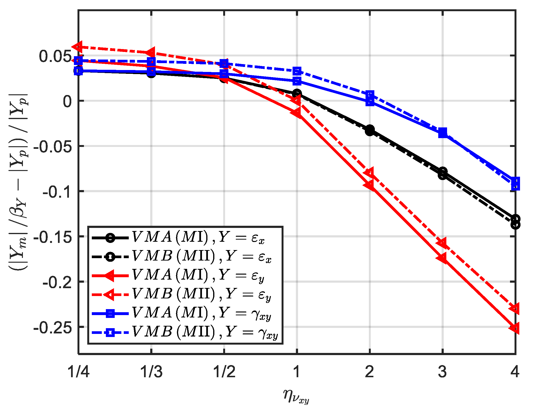
increases from 1/4 to 4, the average error of strain components
,
and
on the time field is shown in
Figure 8. It can be seen that when the scaling techniques MⅠ and MⅡ are used, the similarity error is almost consistent with the change of
. When
, the average error of strain components in the x, y and x-y directions are all about 5%, showing good similarity. Combined with
Figure 7, the main reason is that the Poisson’s ratio contributes less to strain component in both full-size prototype and scaled models. However, when
, the average error increases significantly as
increases. In this case, the strain component
has the largest similarity error (about 10 % and 25% for
and 4, respectively), while
has the smallest similarity error (about 10% for
). Therefore, by designing optimal similarity material to control the value of
(such as
), the similarity loss caused by Poisson’s ratio can be significantly reduced.
(2) Ignoring the shear modulusor the elasticity moduluseasily break similarity.
In the derivation of the scaling technique MⅠ, another important reason for breaking the complete similarity is that the shear modulus
is ignored. While, on the derivation of the scaling technique MⅡ, the elasticity modulus
is ignored. According to Eq. (11), the ideal similar value of
and
are defined as
and
, respectively. The ratio of
to
and the ratio of
to
are expressed as
and
, respectively. For VMA, IM7, E-glass and Steel in the scaling technique MⅠ,
1, 1.9, 2.3 and 5.5, respectively. For VMB, IM7, E-glass and Steel in the scaling technique MⅡ,
1, 0.27, 0.20 and 0.03, respectively. Obviously, except for the virtual material,
and
of other materials are very different from their corresponding ideal values, especially for the isotropic Steel. When combined with
Figure 5i-l and
Figure 6, it can be found that these differences are consistent with the error of the full-size prototype predicted by the scaled model. The above also analysis explains why the similarity errors increase significantly when isotropic Steel different from properties of the full-size prototype is selected for the scaled model. Therefore, better similarity can be obtained for materials with MⅠ whose design parameter
is close to
and for materials with MⅡ whose design parameter
is close to
.
In order to further quantitatively explore the similarity error caused by
, the materials VMA with hypothetical shear modulus in
Table 11 are further used. The scaling factors and numerical models are exactly the same as ‘MⅠ (VMA)’ in
Section 3.1.1, except for shear modulus. When
increases from 1/4 to 4, the average error of strain components
,
and
on the time field is shown in
Figure 9. It can be seen that, when the absolute value of
gets further away from 1, the average error of the strain
and
increases significantly, while the average error of the strain
remains almost zero. In contrast, at the same distance, the similarity error is larger when
than when
. In this case, the strain
has the largest similarity error, even reaching 36% for
. Therefore, by designing optimal similarity material to control the value of
(such as
), the similarity loss caused by shear modulus can be significantly reduced.
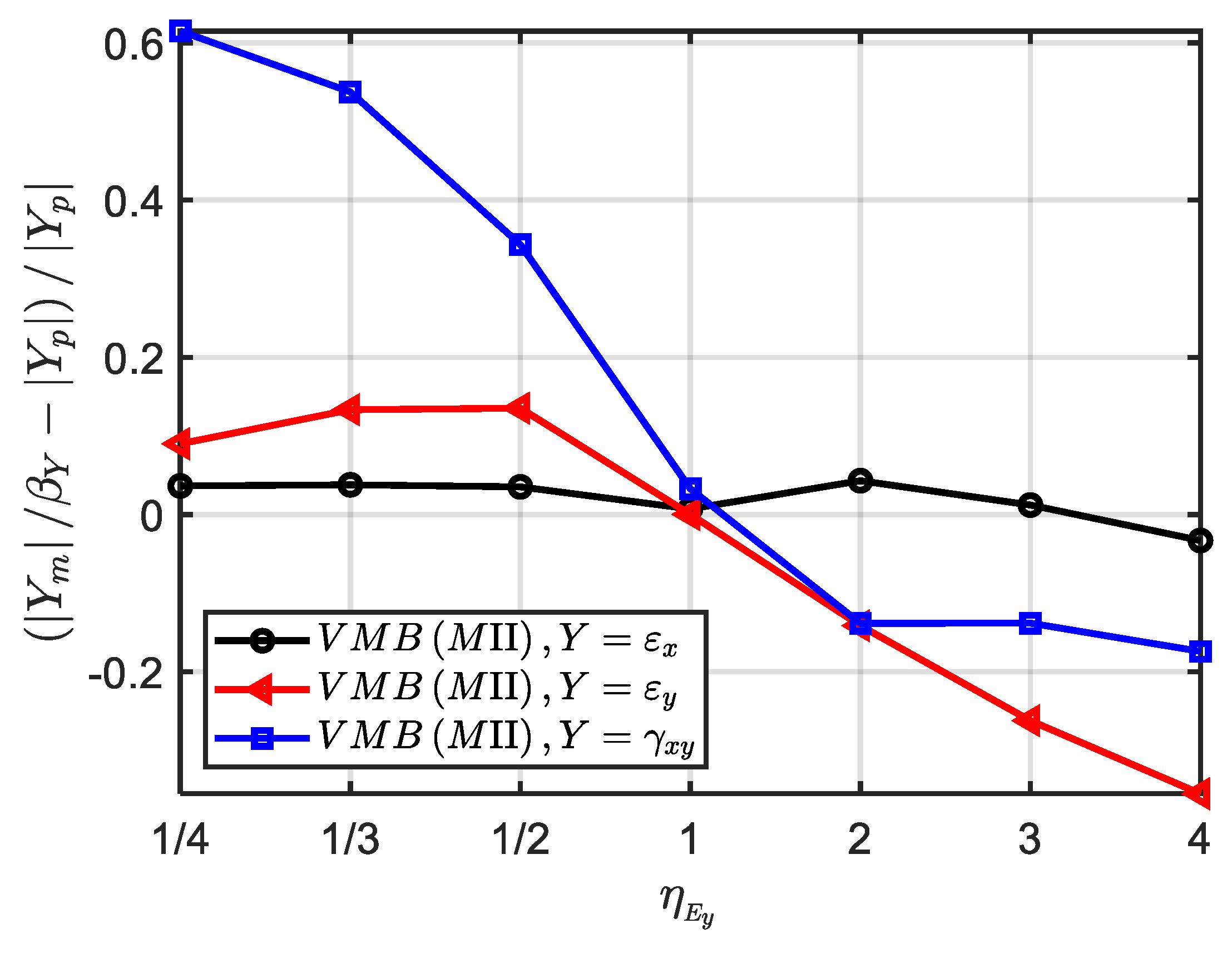
In order to further quantitatively explore the similarity error caused by
, the materials VMB with hypothetical elastic modulus in
Table 12 are further used. The scaling factors and numerical models are exactly the same as ‘MⅡ (VMB)’ in
Section 3.1.1, except for the elastic modulus in the y direction. When
increases from 1/4 to 4, the average error of strain components
,
and
on the time field is shown in
Figure 10. It can be seen that, when the absolute value of
gets further away from 1, the average error of the strain
and
increases significantly, while the average error of the strain
is smaller. In contrast, the strain
has the largest similarity error, even reaching 62% for
. Therefore, by designing optimal similarity material to control the value of
(such as
), the similarity loss caused by shear modulus can be significantly reduced.
(3) The technique MI is easier to get good similarity.
In the results analysis in
Section 3.1.2, the similarity of MI is significantly better than that of MⅡ. For IM7, E-glass and Steel,
1.39, 1.50, 2.35 and
1.3, 3.9, 7.3, respectively. In terms of the Poisson’s ratio
, the scaling technique MⅡ has a larger geometric width distortion capacity and therefore causes greater damage to similarity of the impact plates in
Figure 2. The main reason for this phenomenon is that the width distortion of the technique MⅡ is proportional to the 1/2 power of material parameter ratio rather than the 1/4 power of the technique MI. Therefore, the width distortion of the method MⅡ is more sensitive to the value of material parameter ratio and more likely to cause serious distortion. This difference can be further verified by the values of
and
. When the technique MⅡ is used for IM7, E-glass and Steel, the difference between
and
is intuitively greater than that between
and
, which may also lead to greater similarity error.
In addition, another potential advantage of using the technique MI over the technique MⅡ is when scaled model and full-size prototype use different isotropic elastic materials. In this case, the technique MI naturally degenerates into the geometric similarity with
, while the technique MⅡ may still maintain the width distortion
if
. This means that use of the technique MⅡ will lose some similarity due to width distortion. Recall that, Ref. [
28] takes the stiffness coefficients in the x direction and the x-y plane as the dominant material parameters at incomplete similarity of anisotropic elasticity, which is similar to the scaling technique MⅡ in this paper. The above analysis also indicates that compared with Ref. [
28], the scaling technique MI proposed in this paper have better similarity.
5. Conclusions
This paper presents a distortion similarity laws that relates full-size prototype and scaled model made of same or different anisotropic elasticity materials. In order to explore this method, the recently developed directional similarity law framework (termed as ODLV) are extended by further considering the orthotropic Hooke’s law. The characteristic length of three spatial directions replaces the traditional single scalar characteristic length to express similarity laws of anisotropic elasticity materials, and the correction techniques of the geometric width and thickness of the structure are proposed to overcome the inherent distortion problems of the previous similarity laws. Four are the main aspects in the method outlined here.
(1) Based on the oriented dimensional analysis method and the thin-plate impact model, oriented dimensions, directional dimensionless numbers and directional scaling relations of the elastic modulus and the Poisson’s ratio of anisotropic materials are comprehensively proposed. Compared with the previous scalar dimensional analysis, the directional dimensionless number and directional scaling relation proposed in this paper can effectively express the directivity of geometric space and anisotropic material parameters, which lays a foundation for breaking the limitation of the scaling of material and geometric distortion of anisotropic elasticity.
(2) In order to obtain material and geometric distortion of anisotropic elasticity, three important scaling techniques with correction of width and thickness are further proposed based on the proposed directional scaling relations. Firstly, by ignoring the influence of transverse material parameters, the scaling technique M0 with four dominant similar parameters , , and is proposed. In this case, the scaling relation of the in-plane material parameters is independent of the thickness direction, allowing arbitrary thickness distortion when same anisotropic elastic materials are used for scaled model and full-size prototype. Secondly, the scaling technique MI with dominant similar parameters and and the scaling technique MⅡ with dominant similar parameters and are proposed to further consider distortion case of different anisotropic elastic materials. In the two cases, the geometric width of the scaled model needs to be further reasonably corrected to compensate for the difference in material properties in the x-y plane. This also means that a square plate will be scaled to a thicker/thinner rectangular plate, or a circular plate will be scaled to a thicker/thinner elliptical plate.
(3) The similarity of different anisotropic and isotropic materials is validated by the numerical impact model of a clamped thin square plate subjected to transverse impulse pressure. The results show that when scaling technique M0 is used, all kinds of responses of displacement, stress and strain components on the thin square plate are almost consistent with the full-size prototype on the thicker square plate. When the scaling technique MI is used, the thin square plate is distorted into a rectangular square plate, and the various responses in the x and y directions are consistent with the full-size prototype, while the responses in the x-y direction are significantly different from the full-size prototype. When the scaling technique MⅡ is used, only the transverse displacement is similar, while the responses in other directions have significant errors with the full-size prototype.
(4) The selection criterion of anisotropic material parameters to obtain optimal similarity are analyzed in depth and the applicability of the proposed methods are discussed. The results show that for the thickness distortion of anisotropic elastic materials, the similarity error increases slightly with the increase of the distortion degree. Under the applicable condition of geometric nonlinearity of the ODLV system (i.e., the small strains with moderate rotation (10°-15°) of neutral plane), the scaled model and the full-size prototype has a good similarity. For the width distortion of anisotropic elastic materials, the Poisson’s ratio is not the dominant similar parameter because its influence is not as significant as that of elastic modulus at scaling. The in-plane shear modulus and elastic modulus are the main causes of similarity error. The greater the difference between their values and ideal similar values, the greater the similarity error. In order to obtain good similarity, the materials of scaled model should be designed as close to the ideal similar value as possible. The scaling technique MI could have better similarity than the scaling technique MⅡ, which is mainly due to stronger ability of width distortion in the technique MⅡ, resulting in greater loss of similarity.
Since the proposed similarity laws of anisotropic elastic materials in this paper is limited to the thin-plate impact plate with monolayer anisotropic elastic material, it is necessary to further study for the more complex anisotropic impact problem.
Figure 1.
The thin-plate impact model. (a) a thin-plate subjected to impact loads; (b) the directivity of physical quantities.
Figure 1.
The thin-plate impact model. (a) a thin-plate subjected to impact loads; (b) the directivity of physical quantities.
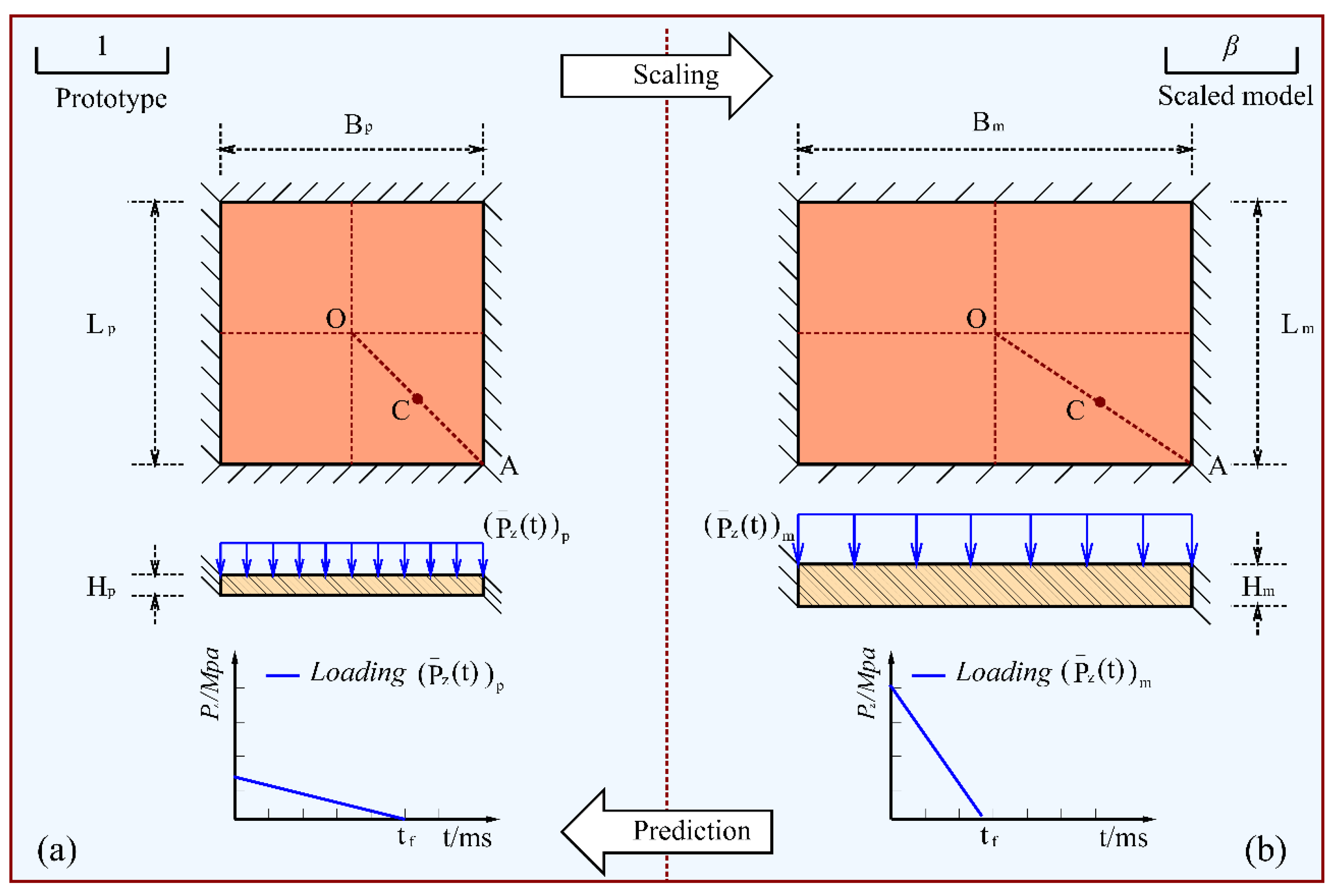
Figure 2.
A scaling schematic diagram of a square plate subjected to a transverse dynamic pressure.
Figure 2.
A scaling schematic diagram of a square plate subjected to a transverse dynamic pressure.
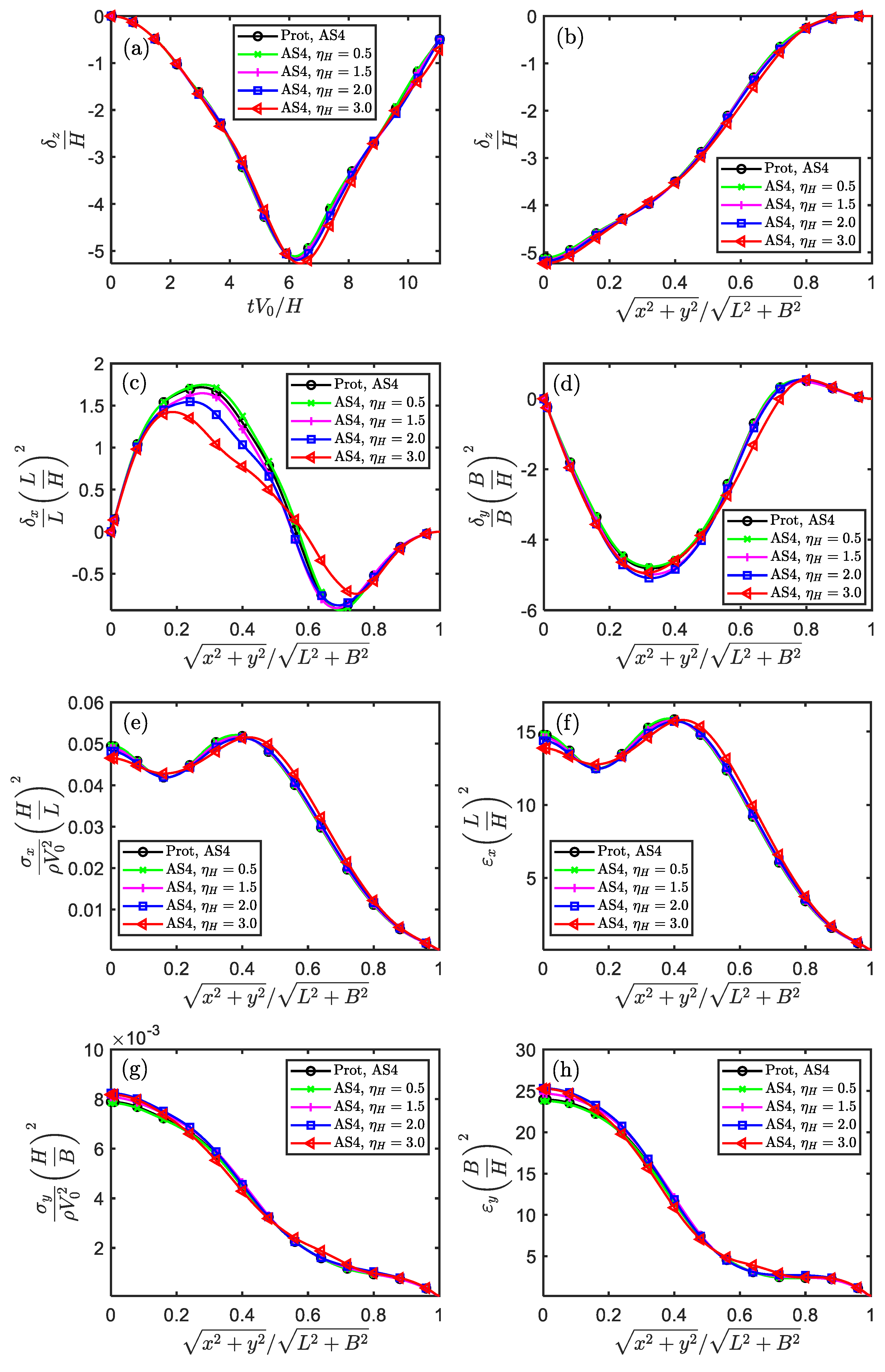
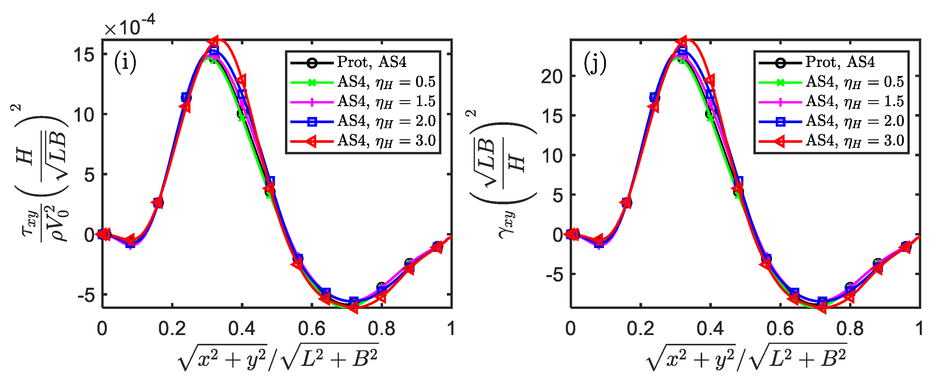
Figure 3.
The similarity of displacement, stress and strain components in the temporal and spatial fields for impacted square plate (Scaling technique M0).
Figure 3.
The similarity of displacement, stress and strain components in the temporal and spatial fields for impacted square plate (Scaling technique M0).
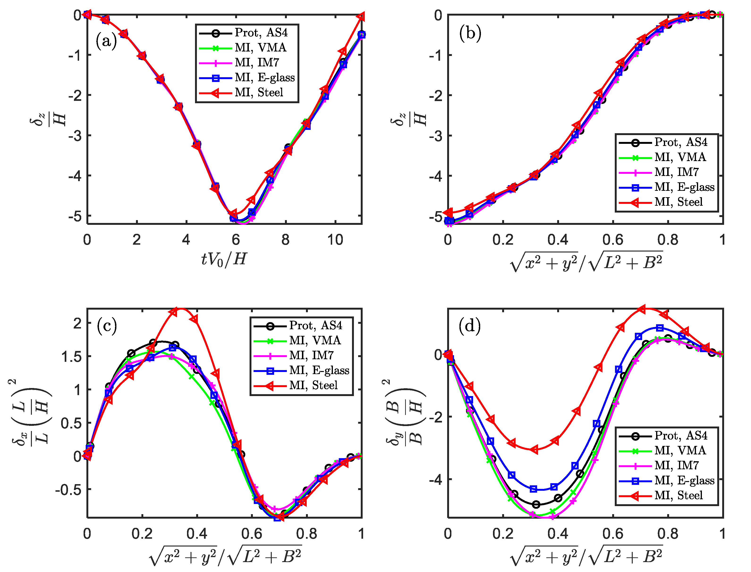
Figure 4.
The similarity of displacement components in the temporal and spatial fields for impacted square plate (Scaling technique MⅠ).
Figure 4.
The similarity of displacement components in the temporal and spatial fields for impacted square plate (Scaling technique MⅠ).
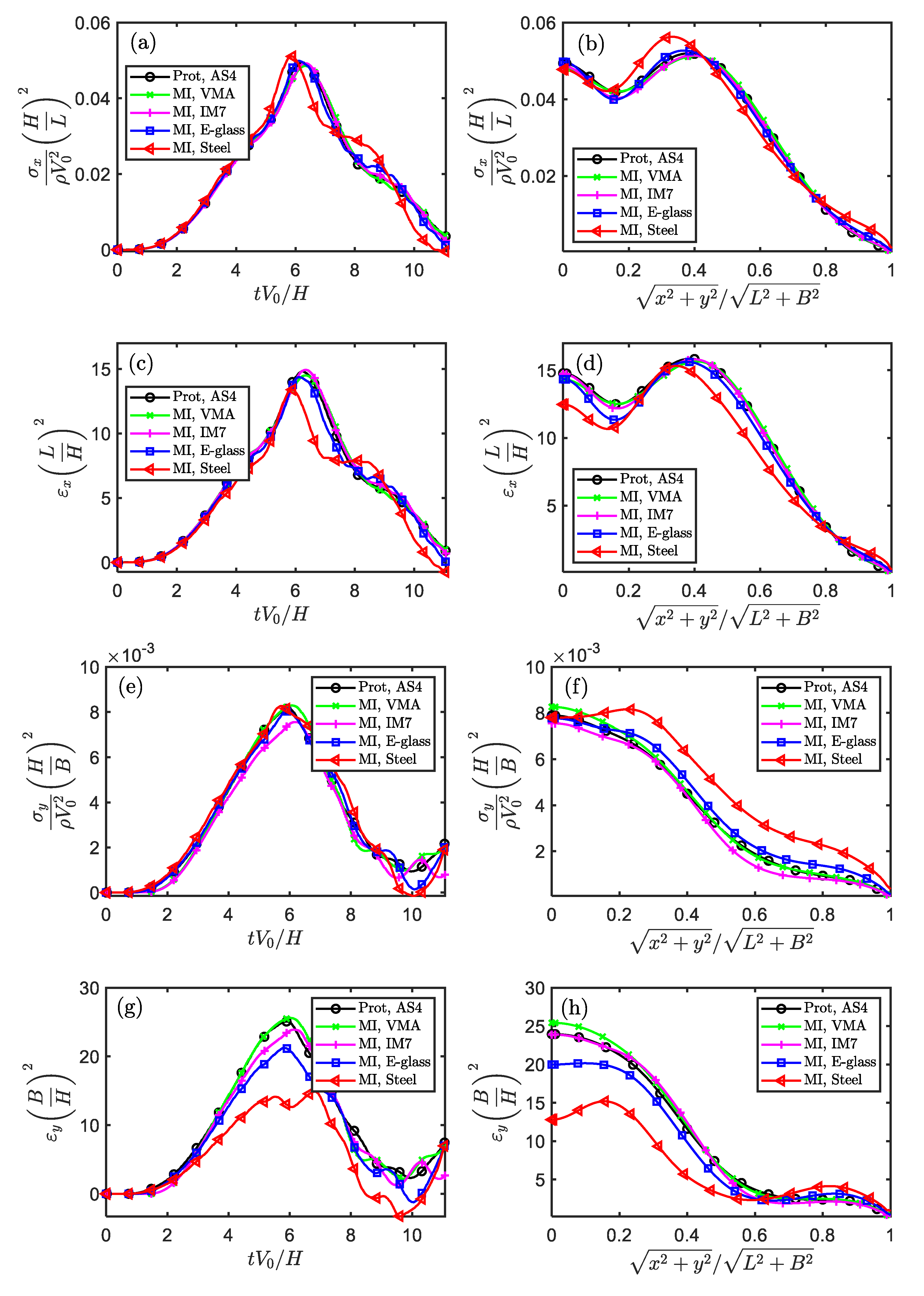
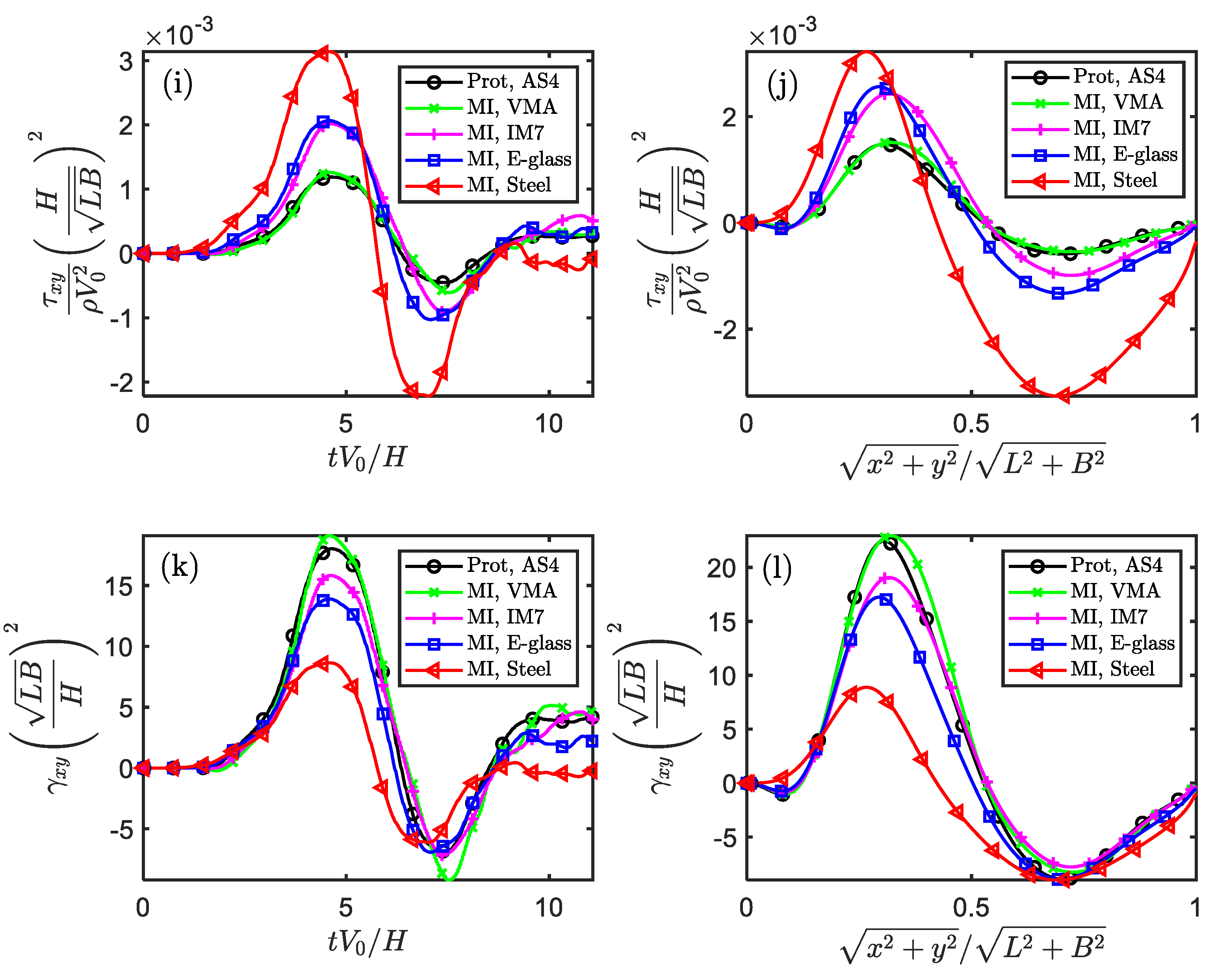
Figure 5.
The similarity of stress and strain components in the temporal and spatial fields for impacted square plate (Scaling technique MⅠ).
Figure 5.
The similarity of stress and strain components in the temporal and spatial fields for impacted square plate (Scaling technique MⅠ).
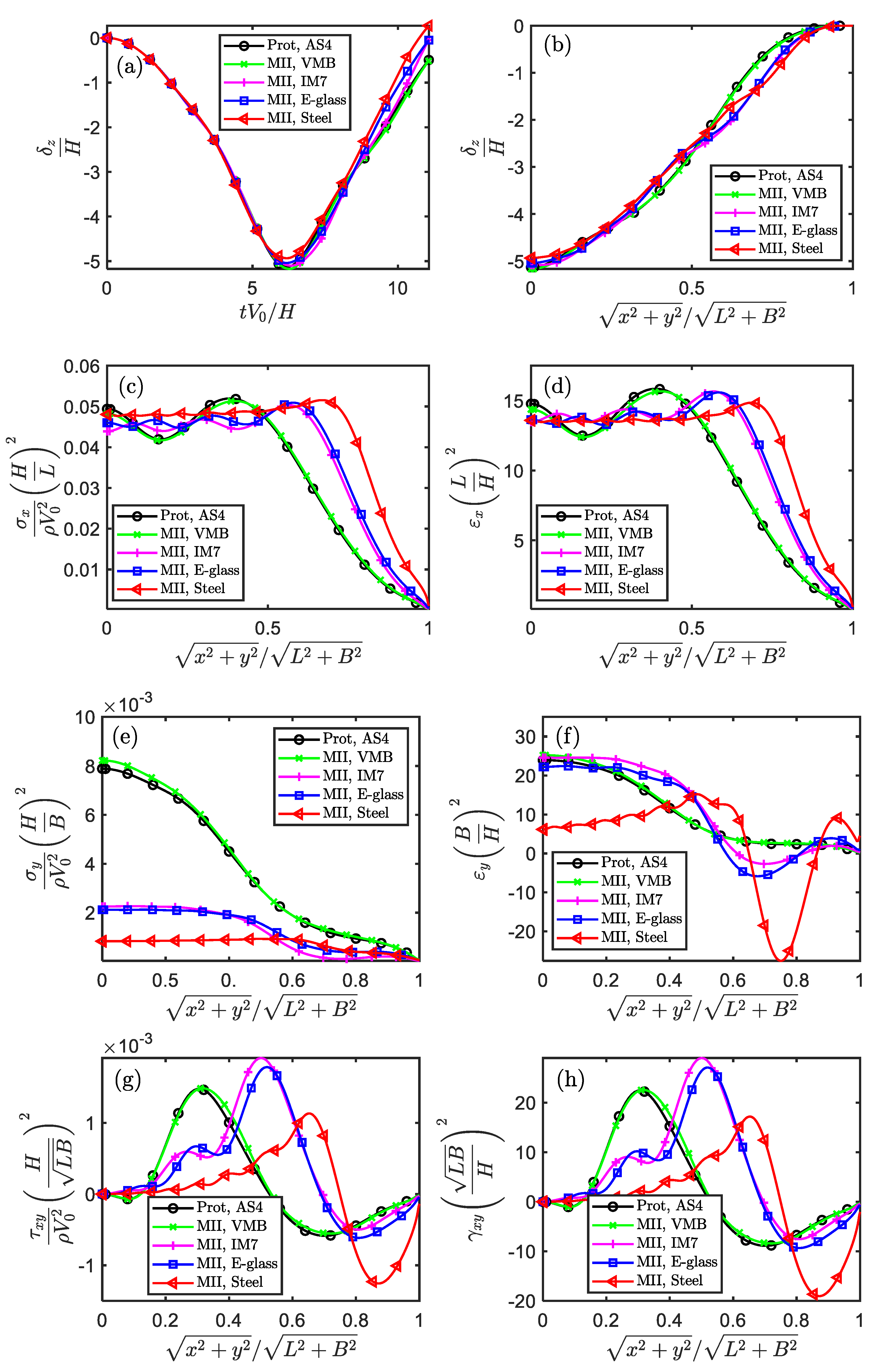
Figure 6.
The similarity of displacement, stress and strain components in the temporal fields for impacted square plate (Scaling technique MⅡ).
Figure 6.
The similarity of displacement, stress and strain components in the temporal fields for impacted square plate (Scaling technique MⅡ).
Figure 7.
The ratio of the normal strain components caused by stress in the and directions for impacted square plate (Scaling techniques MⅠ and MⅡ).
Figure 7.
The ratio of the normal strain components caused by stress in the and directions for impacted square plate (Scaling techniques MⅠ and MⅡ).
Figure 8.
The similarity error of strain components as changes (Scaling techniques MⅠ and MⅡ).
Figure 8.
The similarity error of strain components as changes (Scaling techniques MⅠ and MⅡ).
Figure 9.
The similarity error of strain components as changes (Scaling techniques MⅠ).
Figure 9.
The similarity error of strain components as changes (Scaling techniques MⅠ).
Figure 10.
The similarity error of strain components as changes (Scaling technique MⅡ).
Figure 10.
The similarity error of strain components as changes (Scaling technique MⅡ).
Table 1.
Oriented dimensions of physical quantity in the thin-plate impact problem.
Table 1.
Oriented dimensions of physical quantity in the thin-plate impact problem.
| Physical quantity |
Dimension |
Physical quantity |
Dimension |
|
|
|
|
|
|
|
|
|
|
|
1 |
|
|
|
|
|
|
|
|
|
|
|
|
|
|
|
|
|
|
|
|
|
|
|
|
|
|
|
|
|
|
|
|
|
|
|
|
Table 2.
Main scaling relations of structural impact in the ODLV system.
Table 2.
Main scaling relations of structural impact in the ODLV system.
| Variable |
Scaling factor |
Variable |
Scaling factor |
|
|
|
|
|
|
|
|
|
|
|
|
|
|
|
|
|
|
|
|
|
|
|
|
|
|
|
|
|
|
|
|
|
|
|
|
|
|
|
|
|
|
|
|
|
|
|
|
Table 3.
Oriented dimensions of elastic parameters in the ODLV system.
Table 3.
Oriented dimensions of elastic parameters in the ODLV system.
| Physical quantity |
Dimension |
Physical quantity |
Dimension |
| Elastic modulus, |
|
Shear modulus, |
|
| Elastic modulus, |
|
Poisson’s ratio, |
|
| Elastic modulus, |
|
Poisson’s ratio, |
|
| Shear modulus, |
|
Poisson’s ratio, |
|
| Shear modulus, |
|
|
|
Table 4.
Scaling relations of elastic parameters in the ODLV system.
Table 4.
Scaling relations of elastic parameters in the ODLV system.
| Variable |
Scaling factor |
Variable |
Scaling factor |
|
|
|
|
|
|
|
|
|
|
|
|
|
|
|
|
|
|
|
|
Table 5.
Scaling techniques of distortion for anisotropic elasticity in the ODLV system.
Table 5.
Scaling techniques of distortion for anisotropic elasticity in the ODLV system.
| Scaling techniques |
Dominant parameters |
Scaling relation of aspect ratio |
| M0 |
|
|
| MⅠ |
|
|
| MⅡ |
|
|
Table 6.
Mechanical parameters of materials used for full-size prototype and scaled models.
Table 6.
Mechanical parameters of materials used for full-size prototype and scaled models.
| Materials |
|
|
|
|
|
|
|
| AS4/epoxy [33] |
1580 |
126 |
11 |
0.28 |
2.60 |
2.60 |
3.90 |
| Virtual material A * |
1590 |
162 |
8.34 |
0.36 |
2.57 |
4.96 |
4.96 |
| Virtual material B |
1590 |
162 |
31.12 |
0.19 |
4.96 |
4.96 |
4.96 |
| IM7/977-3 [34] |
1590 |
162 |
8.34 |
0.27 |
4.96 |
4.96 |
4.96 |
| E-glass/epoxy [35] |
1780 |
40 |
10 |
0.30 |
3.15 |
3.15 |
4.32 |
| Stainless Steel [36] |
8000 |
193 |
193 |
0.30 |
74.23 |
74.23 |
74.23 |
Table 7.
Scaling factors of input parameters used for scaled models (Scaling technique M0).
Table 7.
Scaling factors of input parameters used for scaled models (Scaling technique M0).
| Scaled model |
|
|
|
|
|
|
|
| AS4/epoxy |
1.0 |
0.1 |
0.1 |
0.05 |
0.250 |
0.200 |
0.063 |
| AS4/epoxy |
1.0 |
0.1 |
0.1 |
0.15 |
2.250 |
0.067 |
5.063 |
| AS4/epoxy |
1.0 |
0.1 |
0.1 |
0.2 |
4.000 |
0.050 |
16.000 |
| AS4/epoxy |
1.0 |
0.1 |
0.1 |
0.3 |
9.000 |
0.033 |
81.000 |
Table 8.
Scaling factors of input parameters used for scaled models (Scaling technique MⅠ).
Table 8.
Scaling factors of input parameters used for scaled models (Scaling technique MⅠ).
| Scaled model |
|
|
|
|
|
|
|
| Virtual material A |
1.006 |
0.1 |
0.0876 |
0.2 |
4.521 |
0.044 |
20.571 |
| IM7/977-3 |
1.006 |
0.1 |
0.0876 |
0.2 |
4.521 |
0.044 |
20.571 |
| E-glass/epoxy |
1.127 |
0.1 |
0.1301 |
0.2 |
2.123 |
0.094 |
5.079 |
| Stainless Steel |
5.063 |
0.1 |
0.1840 |
0.2 |
2.200 |
0.091 |
24.508 |
Table 9.
Scaling factors of input parameters used for scaled models (Scaling technique MⅡ).
Table 9.
Scaling factors of input parameters used for scaled models (Scaling technique MⅡ).
| Scaled model |
|
|
|
|
|
|
|
| Virtual material B |
1.006 |
0.1 |
0.1218 |
0.2 |
4.521 |
0.044 |
20.571 |
| IM7/977-3 |
1.006 |
0.1 |
0.1218 |
0.2 |
4.521 |
0.044 |
20.571 |
| E-glass/epoxy |
1.127 |
0.1 |
0.1954 |
0.2 |
2.123 |
0.094 |
5.079 |
| Steel |
5.063 |
0.1 |
0.4317 |
0.2 |
2.200 |
0.091 |
24.508 |
Table 10.
Hypothetical parameter of Poisson’s ratio for the material VMA and VMB.
Table 10.
Hypothetical parameter of Poisson’s ratio for the material VMA and VMB.
|
1/4 |
1/3 |
1/2 |
1 |
2 |
3 |
4 |
|
0.09 |
0.12 |
0.18 |
0.36 |
0.72 |
1.08 |
1.44 |
|
0.0475 |
0.063 |
0.095 |
0.19 |
0.38 |
0.57 |
0.76 |
Table 11.
Hypothetical parameter of shear modulus for the material VMA.
Table 11.
Hypothetical parameter of shear modulus for the material VMA.
|
1/4 |
1/3 |
1/2 |
1 |
2 |
3 |
4 |
|
0.643 |
0.857 |
1.285 |
2.57 |
5.14 |
7.71 |
10.28 |
Table 12.
Hypothetical parameters of elastic modulus for the material VMB.
Table 12.
Hypothetical parameters of elastic modulus for the material VMB.
|
1/4 |
1/3 |
1/2 |
1 |
2 |
3 |
4 |
|
7.78 |
10.37 |
15.56 |
31.12 |
62.24 |
93.36 |
124.48 |
