1. Introduction
Visual programming languages (VPLs) such as Pure Data [
1] and Max/MSP [
2] are domain-specific languages (DSLs) used for developing computer-based audio processing. Also, they can provide audiovisual processing capabilities through libraries such as Gem [
3] and Jitter [
4]. These languages have been used in live performances due to their real-time visual operation, as well as in audio-related research for music analysis [
5], digital musical instruments [
6], computer-assisted musical composition [
7] and academic courses on musical interactions.
VPLs enforce a programming paradigm based on connecting processing blocks. Each block performs a transformation to its input, and some blocks can immediately be used as a human-computer interface, similarly to physical multimedia equipment. This similarity enables learning programming languages by association to other multimedia processing environments, which facilitates using algorithms in real-time music composition.
Algorithms have been widely used in the music domain to systematically create variations, as it is the case of the pre-XX Century Musikalisches Würfelspiel (Music Dice Games) [
8] (from which the one attributed to Mozart is the most famous) and John Cage’s Music of Changes [
9]. Also, they can be used as basis for musical composition, as in Xenaki’s Formalized Music [
10]. More recently, Machine Learning [
11] algorithms have been used to generate models able to compose new music based on patterns found on existing musical data. However, these algorithms generate musical sequences as a monolithic black box, and do not provide the human composer with control regarding the automated composition [
12].
Algorithms and other formal representations can help to analyze, clarify, and creatively manipulate several aspects of musical structures [
13]. However, they can be insufficient to represent the various nuances that composers can embed into their pieces based on their creative intentions [
13], which leads composers to manually change the algorithmic outcomes [
14]. For this reason, algorithms are often used to generate short excerpts within larger pieces [
7], or as frameworks that can suggest musical elements that are later changed by the composer [
10,
15].
Arguably, there is a subtle limit between making music with algorithms and sonifying algorithms [
16]. Making music is linked to a specific artistic intent, whereas sonifying simply means proposing auditory displays. However, because there can be some artistic intent in sonification, and some level of auditory display in making music, both activities are often confused.
Some initiatives, for example, explore the sonification of computer language constructs with an aim on facilitating debugging [
17,
18,
19]. As observed later, this same concept can be further expanded to general-purpose sonifications [
19]. Also, the sonification of more complex software systems, like operating systems [
20], can generate musically interesting sounds, even if its initial intent is an auditory display.
This intersection between sonification, music composition and computer constructs has also lead to the creation of Pulsed Melodic Affective Processing [
21]. This technique consists on manually mapping desired affective outcomes to music composition counterparts using fuzzy logic gates. Hence, this mapping can be interpreted as memoryless logic, that is, the constructs are similar to the logic gates used in digital design.
In this article, we analyze a seldom explored method to implement algorithms in music-domain VPLs, namely the Finite State Machine with Datapath (FSMD) [
22], which is a well-known structure used in digital system design [
23]. It allows the systematic and direct implementation of algorithms in VPLs, which in turn allows the artistic exploitation of the Turing-completeness of exposed machines whose parts can be mapped onto musical elements according to the musician’s intentions.
The Finite State Machines (FSMs) within the FSMDs can be musically used similarly to the Markov Chains [
10], that is, each state is mapped to a discrete event. However, the path through the FSM while executing an algorithm is deterministic. This makes it possible both to repeat the same path (by executing the same algorithm with the same parameters) and to create variations (by changing the algorithm’s parameters).
Simultaneously, the FSMD’s inner variables can be mapped to musically-relevant aspects. They can be used to control continuous elements such as gains, filters, and other audio timbre parameters. The inner variables are intertwined with the FSMs, and, likewise, their behavior is deterministic for each set of algorithm parameters.
Exposing both the inner variables and the FSM allows jointly exploring both of these sources for music control. This exploration is further facilitated by having the whole structure within a single VPL, instead of importing external constructs. Henceforth, although FSMD implementation can have a difficult learning curve, this structure can foster a broad diversity of musical explorations.
This bridges a gap between the visual and imperative programming paradigms and allows the use of use algorithms and algorithm theory in the process of producing art with VPLs. Although imperative algorithms have been previously implemented in VPLs [
24], the approach described in this work is systematic, can be easily applied to all algorithms expressed in the imperative paradigm, and, additionally, allows loops and iterations to be synchronized with musical elements.
As discussed in
Section 2, this method is based on changing the implicit synchronization method in VPLs (using “hot” and “cold” inlets) to an explicit synchronization method (using “bang” messages similarly to the “clock” border trigger in digital circuits). This allows the creation of patches that operate upon request. They are combined to generate finite state machines (FSMs) whose states change synchronously to the input “bang” messages. Their behavior is similar to sequential logic blocks used in digital design [
23]. In addition, we extensively use the
mux and
demux objects, which can be found in the Zexy Pure Data library.
The FSM states control the data flow in a separate memory space, which is called
datapath. Likewise, the memory states are taken into account when changing the FSM states. All of these structures are exposed and can be mapped to sound-related elements, thus leading to music composition based on the literal inner workings of these algorithms. Although there are some FSM implementations that can be found online
1, we show how to implement the FSM directly in the VPL environment, which reduces the dependency of externals.
We implemented the well-known Euclid’s Greatest Common Divider algorithm using the FSMD and used it in two musical proposals, which are shown in
Section 3. In the first proposal, we control high-level musical structures in a minimalistic composition [
25]. In the second one, we control parameters in a FM synthesizer [
26] in order to generate different timbres.
The paradigm shift discussed in this article is a formally correct method to implement algorithms and it facilitates artistic applications of computer science theory. It exposes the inner workings of the algorithm, which allows using both the the calculation processes and the final results as material for music making. This is especially important in experimental algorithmic music and live coding, as it gives access to vast exploration possibilities. These remarks are detailed in
Section 4.
2. Implementing FSMDs
Previous work by Kraemer and Poepel [
24] presented an analysis of the implementation of Euclid’s Greatest Common Divider (GCD) algorithm in Pure Data. Their implementation yielded correct results, but resulted in a deep refactoring of the algorithm aimed at transforming it to the data flow paradigm. They argue that this re-factoring was necessary due to paradigm translation difficulties related to the visual language.
First, Kraemer and Poepel [
24] observe that the order of operations is related to their visual position on screen, which can lead to inconsistencies that can be hard to detect. Second, they state that variable value assignments have no immediate correlate in Pure Data. In addition to that, we note the absence of explicit branch and loop structures as another problem in VPLs.
In this section, we discuss a visual data flow programming techniques that aims to overcome these problems. It is based in FSMD design tools and methods [
22,
23]. The remainder of this section is organized as follows. Sub
section 2.1 presents a description of the VSL blocks that can be used to overcome the problems pointed by Kraemer and Poepel. After that, sub
Section 2.2 and
Section 2.3 respectively discuss how to systematically implement a finite state machine and a datapath. Lastly, Sub
section 2.4 demonstrates the paradigm shifting procedure using an implementation of Euclid’s GCD algorithm.
2.1. Elementary blocks
The programming paradigm problems pointed by Kraemer and Poepel [
24] can be solved using native Pure Data techniques. The problem related to the order of operations can be solved using the native Pure Data
trigger object. The problem of variable assignment is solved using the
float object, which behaves similarly to D-type registers [
23]. They are both described in the remainder of this subsection.
2.1.1. Explicit Operation Precedence
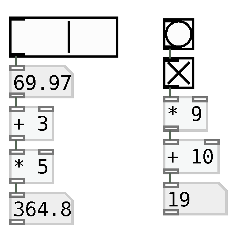
Pure Data implements event-reactive objects, that is, objects that yield outputs upon receiving an input. The output of an object can be routed to the input of another one, as shown in
Figure 1. Routing an output to two or more objects implicitly causes parallel objects to be executed sequentially, in the same sequence that the connectors were added.
Multiple-input Pure Data objects commonly use inlets with two different behaviors, namely hot inlets and cold inlets. Hot inlets are those that trigger the output of an object, and cold inlets only cause changes in the object’s inner state, storing it without changing its output. Typically, the first (leftmost) inlet is hot while the others are cold.
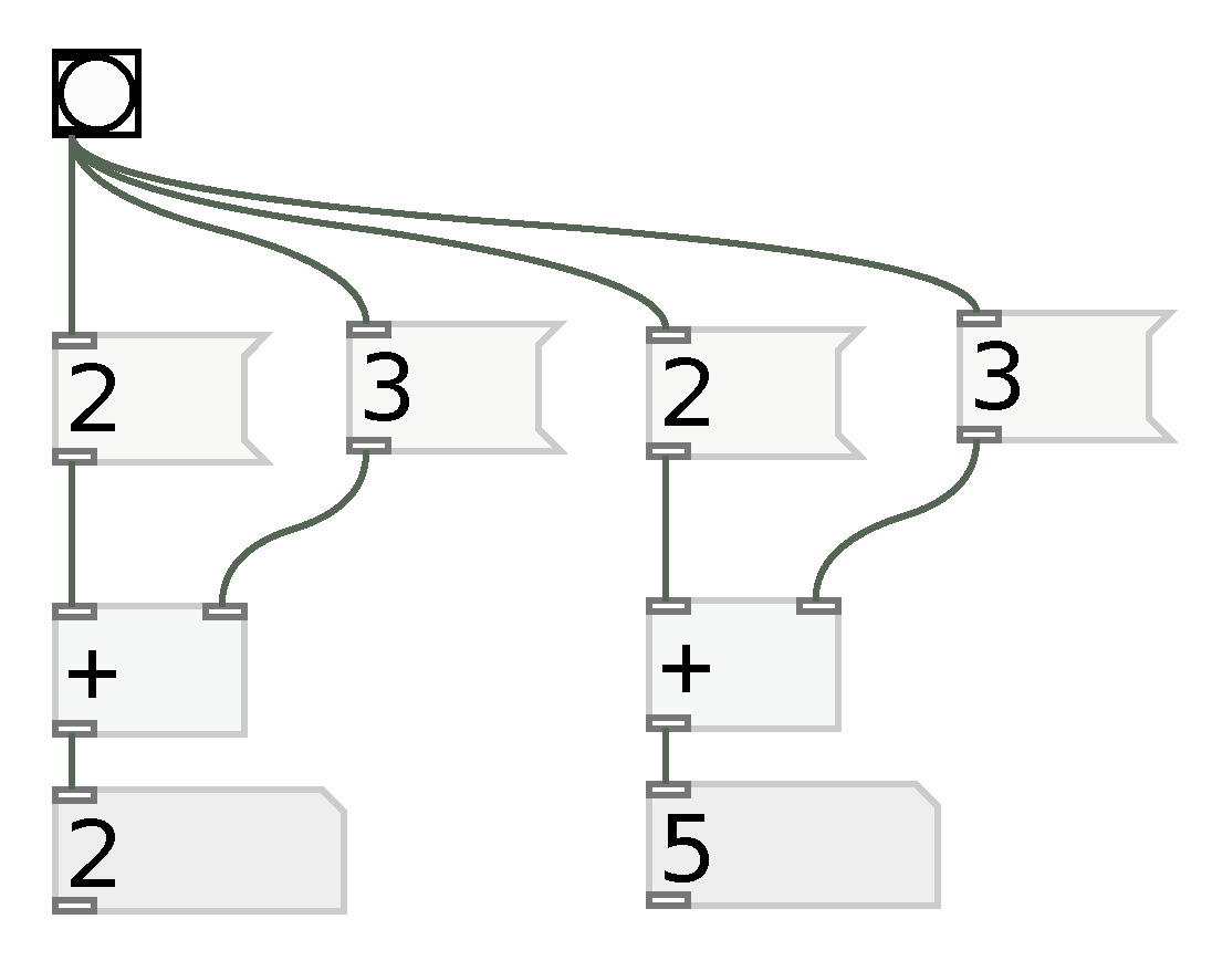
This can lead to ambiguous situations, as the one shown in
Figure 2. In this situation, the
bang signal simultaneously triggers number messages, which means they are executed according to their order of creation. This means that patches that look strictly equal can have different outputs due to the hot-cold inlet behaviors.
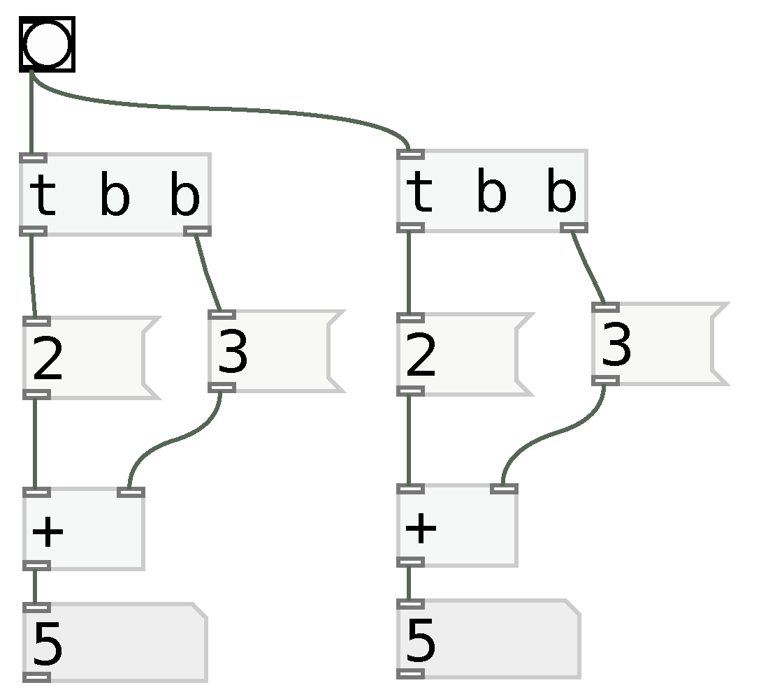
Pure Data implements an object that solves this issue. The object is called
trigger, or simply
t. It sequentially yields outputs in its outlets from right to left. Hence, the precedence problem can be solved using the structure shown in
Figure 3.
2.1.2. Clock-Synchronous Variable Assignment
Values in Pure Data and Max/MSP can be used for audio and music control. They differ from a variable because changing them immediately changes the behavior of objects further ahead in the processing chain. This can be a problem when implementing algorithms because variables are often used to store intermediate values, hence changing their behavior incurs in deep changes in the implementation, as observer by Kraemer and Poepel [
24].
This problem can be solved by using the
float object
2 for synchronization. A
float object can receive values in its right inlet, but they only propagate to the output when a
bang message is received in the left inlet. This behavior is similar to a D-Flip-Flop register in which the data bus corresponds to the right inlet and the clock input corresponds to the left inlet [
23].
The
float object can be used to explicitly synchronize operations to a
bang signal. For such, the end of the operation chain is connected to the
float object right inlet and a
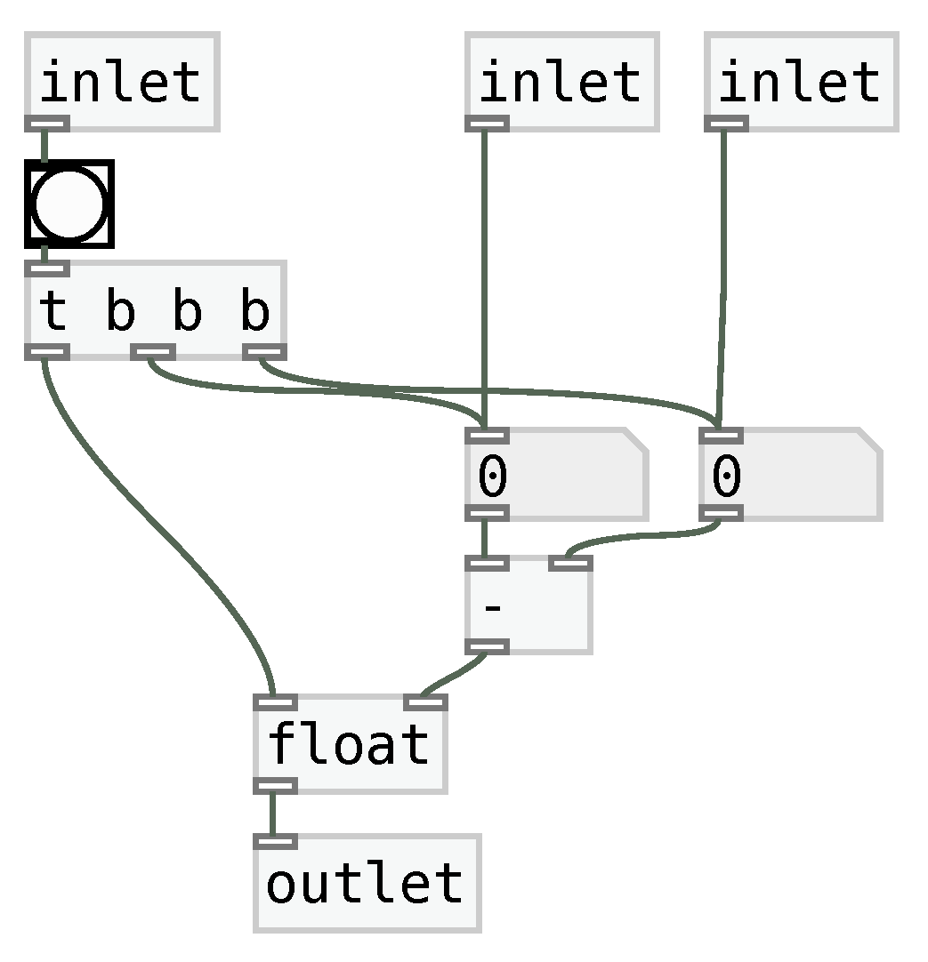
bang signal is connected to its left inlet, as shown in the patch depicted in
Figure 4.
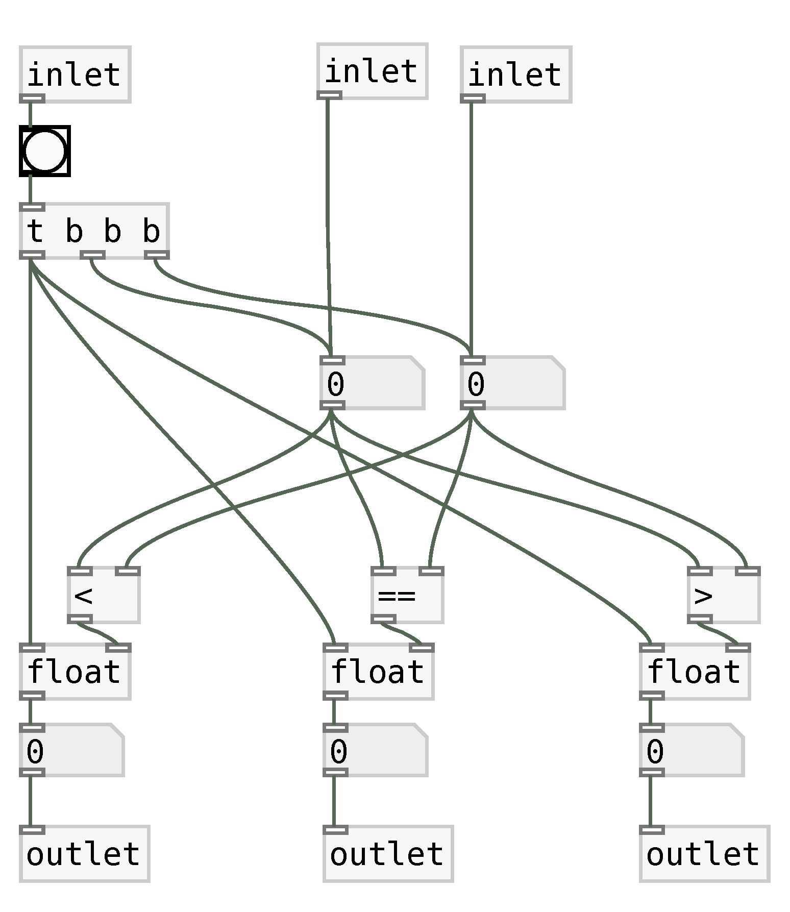
The patch shown in
Figure 4 receives numbers as inputs in the second and third inlets, which are stored as internal patch values. Upon receiving a
bang message in the first inlet, both numbers are propagated further, which updates the native Pure Data subtraction operator. After these operations, the
trigger object sends a bang message to the
float object, finally propagating the result to the outlet.
The techniques shown in this section allow both variable assignment and operation execution to be synchronized to an external source of control. As a consequence, they can be synchronized to a finite-state machine, as discussed in the next section.
2.2. Finite State Machines
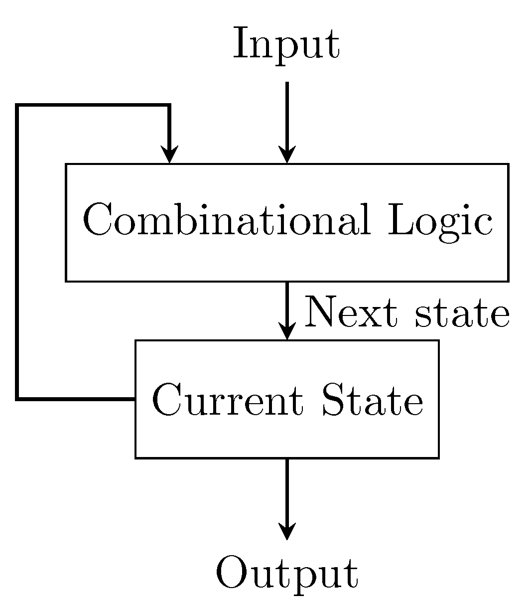
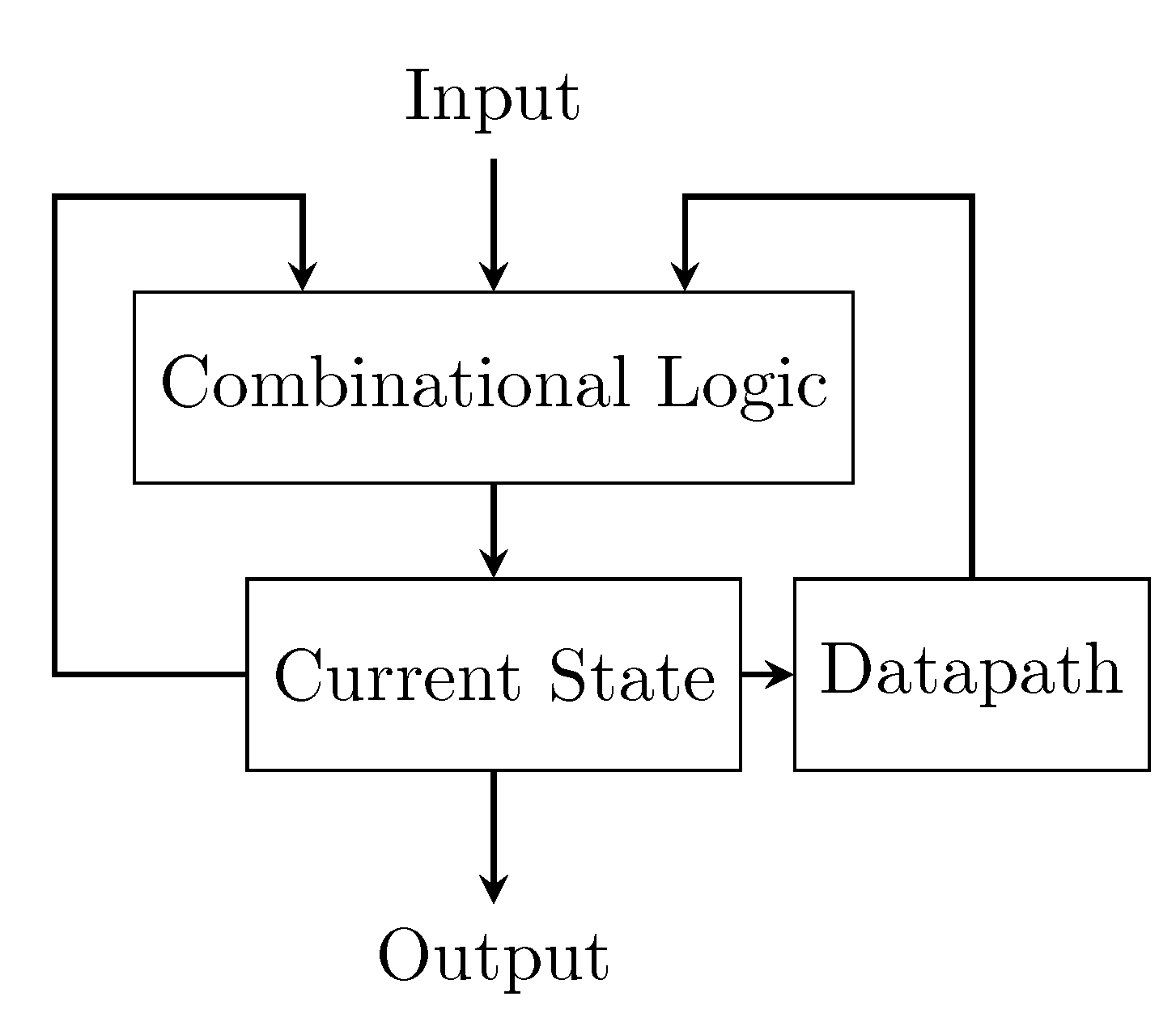
A finite-state machine (FSM) is a computational model in which the computing machine has a finite number of states and only one of them is active at each time. A synchronous FSM changes its state upon receiving a specific signal. The next state (i.e., the state to which the machine will switch) is calculated as function of the current state and the inputs of the machine, as shown in
Figure 5.
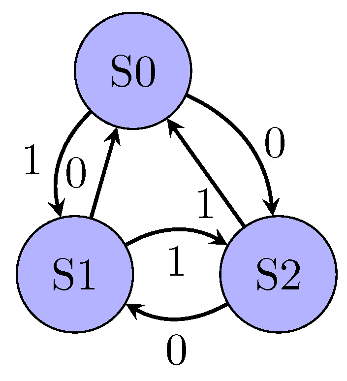
FSMs can be displayed using a bubble diagram, as shown in
Figure 6. This representation highlights the inputs related to the transitions between states. For example, in the bubble diagram shown in
Figure 6, a clock signal in state S0 with input 0 would cause a change to state S2.
Another convenient representation for the FSM is a state transition table, as shown in
Table 1. This representation explicitly shows a function that calculates the next state using the current state and the input.
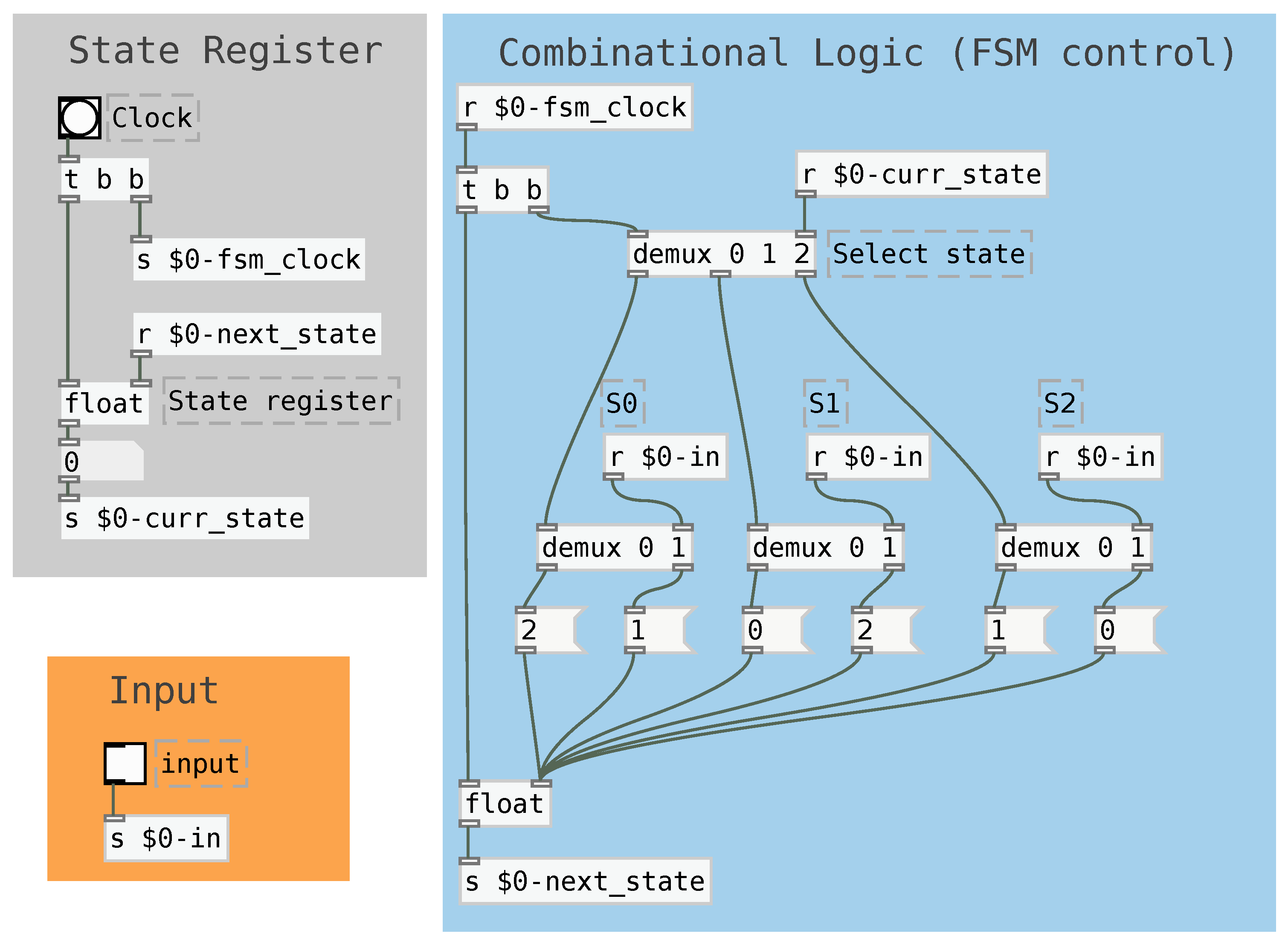
The FSM can be implemented in Pure Data, as shown in
Figure 7. For such, a
float object can be used as a state register. This memoryless logic can use separate branches to implement each state’s behavior and a demultiplexer to select between them.
In this implementation, a clock signal (in the top of the light gray box) triggers the calculation of the next state. This calculation starts by using the a demultiplexer (shown in white, commented as “select state”) to route the clock signal into the objects related to the current state. After that, the next state is calculated using the manual input and then routed to the state register inlet. Finally, the state register’s clock inlet is dispatched and its value is updated.
The input signal can be used as a synchronous reset control by changing all state transitions so that an input equal to 1 always makes the next state equal to the machine’s initial state. This means that a reset signal equal to 1 forces the next state to the initial one, whereas a 0 signal allows the machine to execute normally. In addition to simply restarting, the synchronous reset device allows halting the FSM at the initial state, which can be useful for musical control.
The FSM cannot store intermediate values, which prevents it from universally calculating algorithms. This capability can be provided by using a set of structures called datapath, as discussed in the next section.
2.3. Datapath
A datapath is a set of structures that allows logic and arithmetic operations to be executed and their results stored. As shown in
Figure 8, it consists of three layers. The first one is an initial layer of operators, whose results are stored in the registers that are in the second layer. The third layer takes values from the register and performs operations whose results are yielded to the FSM control.
The operators are implemented as memoryless logic in low-level digital design because, in this context, the clock signal related to the state changes is responsible for the machine synchronization. However, the Pure Data implementation requires updating each layer of the dataset in the correct order, that is, first the data operators, then the data registers and last, the output operators. This results in implementations similar to that shown in
Figure 9.
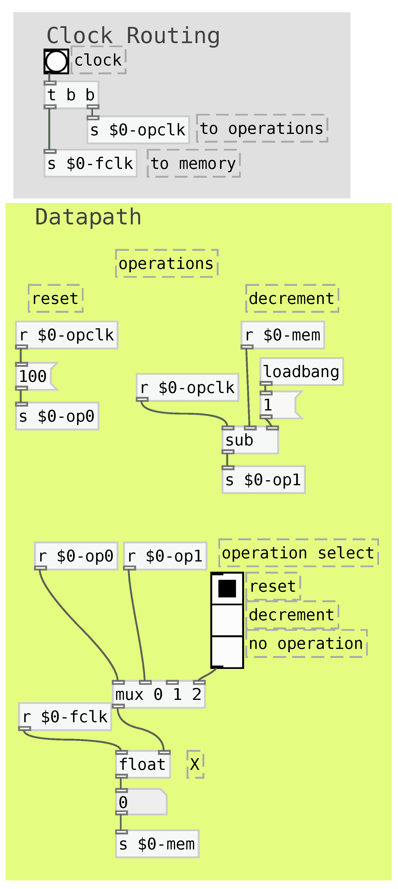
The Pure Data implementation uses a float object to implement the memory registers, and clock-synchronous operations to implement the operators. The datapath operators are divided into the data operators, highlighted in dark gray, and the output operators, highlighted in black. All operators can receive data register values as inputs. The data operators update the internal memory values, whereas the output operators simply yield binary (1 or 0) values.
As highlighted in the light gray box in
Figure 9, the clock signal is routed first to the data operators, then to the memory register and, after that, to the output operations. This ensures that all operations are executed in the correct order
A multiplexer is responsible for selecting the operation result that is yielded to the memory register’s data inlet. This structure allows using pre-fixed assignments for reset or pre-set operations. Last, the multiplexer can have empty inlets to represent no-operation, i.e., an operation that does not change the memory register’s value.
The datapath must be especially designed for each algorithm. It must comprise one register (with a corresponding multiplexer) for each variable in the algorithm, and a specific implementation for each required operation.
A datapath can be integrated with a FSM. For such, the results of the output operators are used as inputs in the FSM, and the FSM’s state register is used to control the operator selection multiplexer in the datapath. This leads to the system structure shown in
Figure 10.
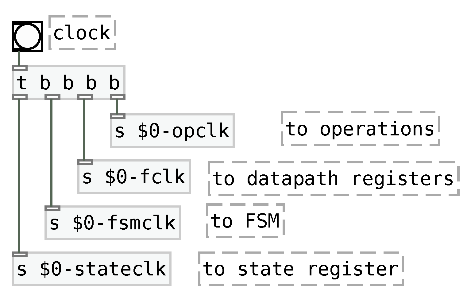
Although low-level digital FSMD design allows using a single clock signal to all registers in a circuit, the Pure Data implementation requires a more careful process for clock routing. This routing accounts for the facts that the calculation of the next state requires estimating conditions in the FSM, that these conditions depend on the datapath register values, and that the datapath register values depend on the operator results. For this reason, the clock signal must be routed first to the datapath operators, then to the datapath registers, then to the FSM estimation and, last, to the state register clock, as shown in
Figure 11.
The Finite State Machine with Datapath is Turing-complete in relation to its computational power [
23]. It can be used to implement algorithms written in imperative languages, as shown in the next section.
2.4. Demonstration
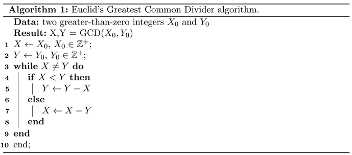
In this section, we demonstrate an implementation of Euclid’s Greatest Common Divider (GCD) algorithm using an FSMD programmed in Pure Data. The GCD algorithm is shown in Algorithm 1.
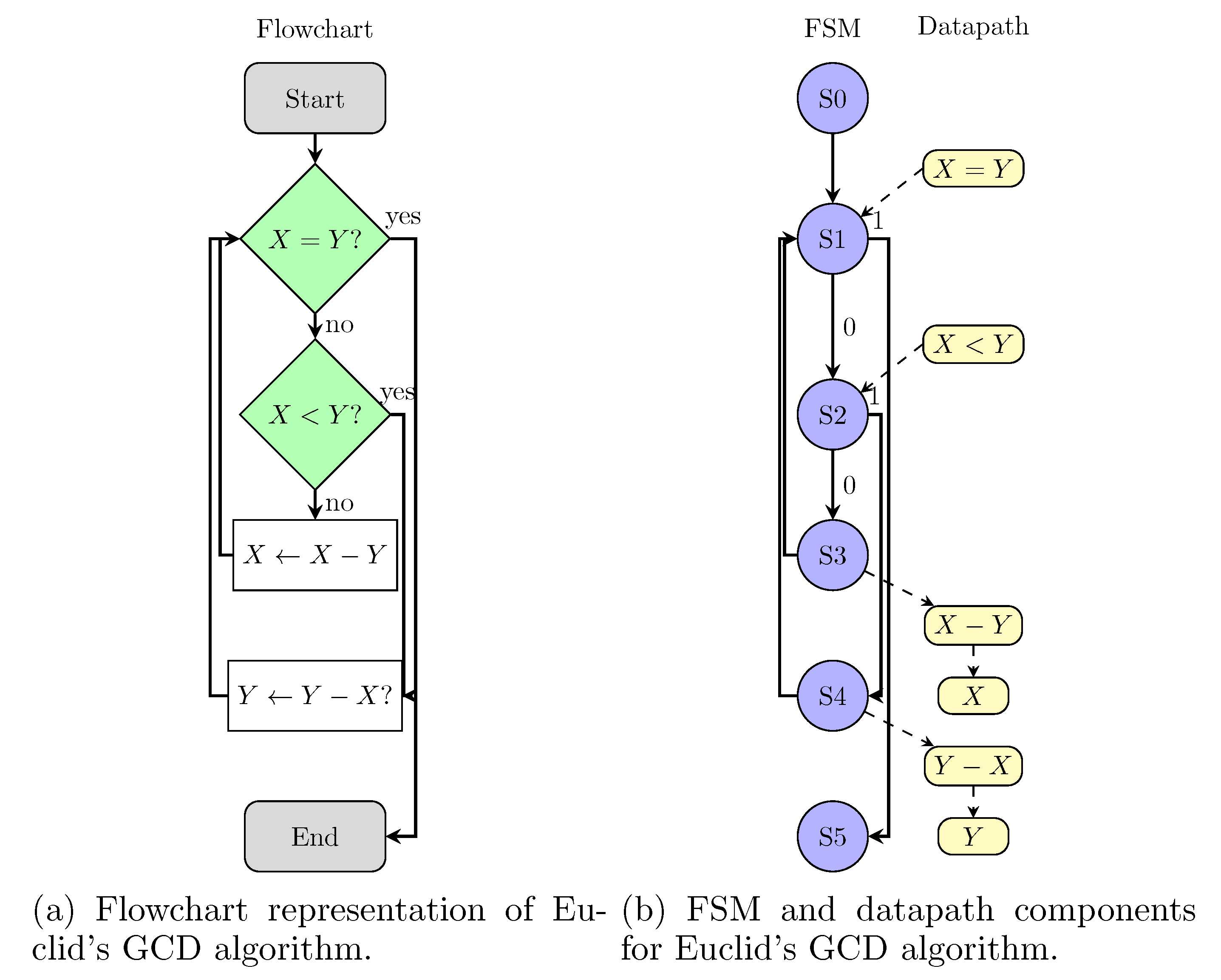
The algorithm can be converted to a flowchart, as shown in
Figure 12. The flowchart can be immediatelly converted to Finite State Machine (FSM) blocks and datapath elements, as shown in
Figure 12. This representation highlights that the algorithm requires six states (S0 to S5), two variables (
X and
Y), and operations to subtract (
and
) and to evaluate if
and if
.
The subtraction operation can be implemented using the patch shown in
Figure 4, which was named
sub. The value comparison between
X and
Y require implementing a comparator, shown in
Figure 13. Similarly to the subtractor, the
comparator object has one “clock” and two “data” inlets,
X and
Y. The three outlets respectively correspond to the Boolean results of
,
, and to
.
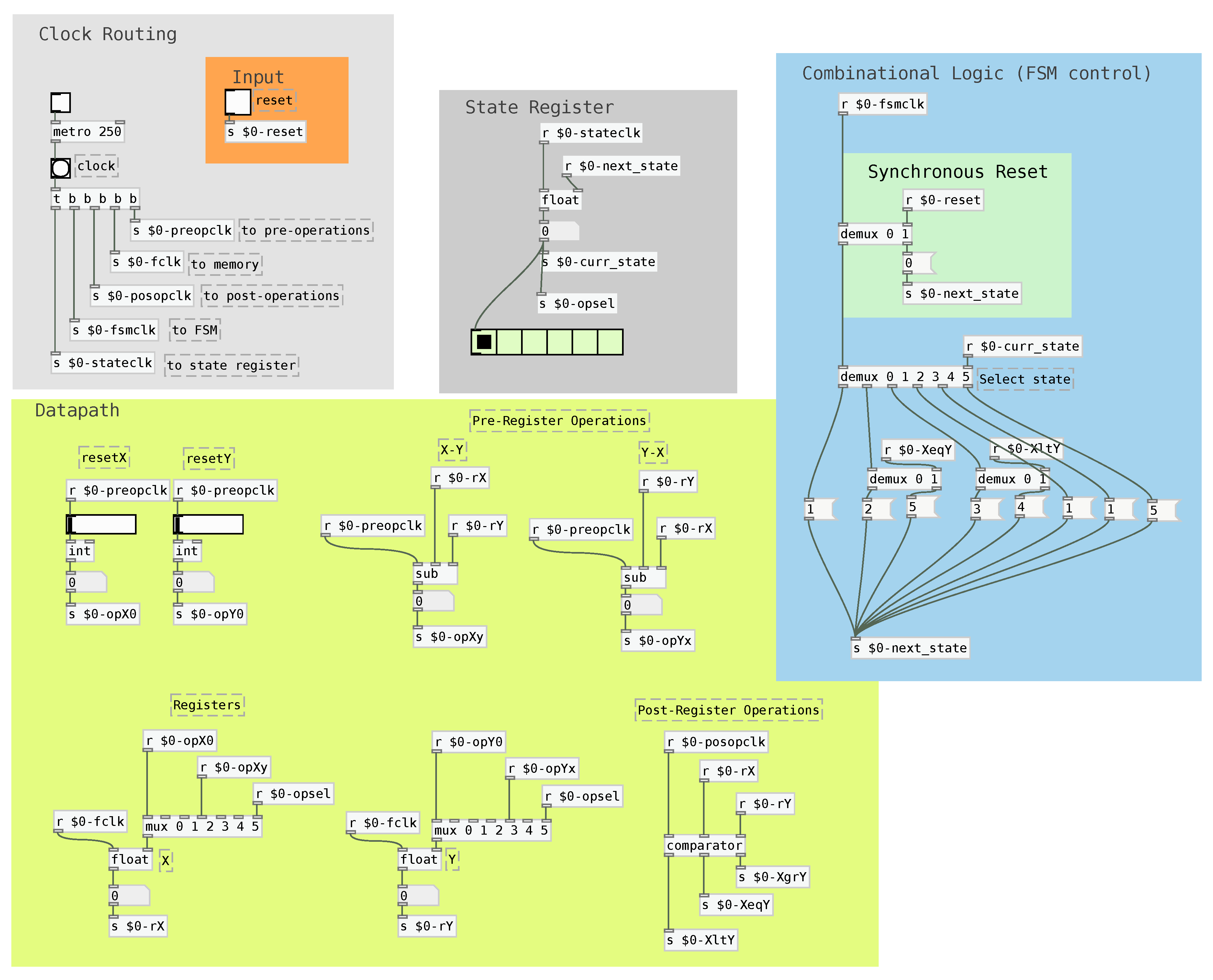
After this, the GCD algorithm can be immediately implemented using the FSMD strategy as shown in
Figure 14. The implementation contains a FSM, a Datapath, a State Register, a Clock Routing structure and an Input selector.
An important feature for FSMD control is the possibility of resetting it to the initial (or another required) state. This capability is provided by the synchronous reset strategy, which forces the FSM to its initial state upon receiving a clock signal. It can be implemented by adding a special condition to each of the states, but a more compact implementation can be achieved by introducing a multiplexer prior to the FSM multiplexer, as highlighted in green in
Figure 14.
In this implementation, if the reset toggle is activated, then the machine resets to state S0, which loads the the values of the resetX and resetY faders to the state registers X and Y. This allows to restart the algorithm with new values to calculate the GCD.
It is important to carefully configure the clock routing order. First, the pre-register operations (subtractions) must be calculated. Then, the register values are updated. After that, the operations that depend on new register values (post-register operations, which correspond to the comparator) are calculated. Subsequently, the FSM next state is calculated and, finally, the state register is updated.
3. Demonstrations
The FSMDs discussed in this article can foster a diversity of musical explorations. Because their structures are completely exposed, they can be yielded to further algorithmic processes. Also, we note that the FSM and the Datapath draw intertwined dynamics that can be respectively used to control sequences of discrete events and to generate complicated envelopes.
The demonstrations discussed in this section use the GCD as implemented in
Section 3. The GCD algorithm receives two numbers (
and
) as inputs. They are stored in internal variables
X and
Y that progressively decrease until the algorithm stops. The initial conditions define a path through the corresponding FSM. The FSMD’s real-time speed can be increased or decreased by changing the clock period.
To demonstrate the use of this method for musical purposes, we present here two implementations, one in the musical macro-structural time domain and another in the micro-structural time domain. The macro-structural time domain deals with acoustic structures that convey musical context. For that, they ought to occur in a time window larger than the
specious present, a concept already treated by the famous XIX century psychologist William James, which refers to the conscious perception of “now”. It is a time window within which events are still perceived as simultaneous (like a chord) or grouped together (like an arpeggio), even if they are not physically simultaneous. This experienced moment is being studied by many [
27,
28,
29] and helps to understand the interplay between perception and cognition.
Above the
specious present, the listener can retrieve information of identification (“what is it”) and emotional content (“what it means”, or “how I feel about it”). The time window related to the
specious present has been empirically described as being about 1 to 3 seconds [
30].
In music, one second of sound is usually sufficient duration for many listeners to be able to identify several musical features, such as melodic phrases, harmonic cadences, voices and musical instruments, rhythm, time, key, etc. Above three seconds, most listeners can appraise the emotional content of a musical excerpt.
The micro-structural domain deals with an even smaller time window than the specious present. It is normally agreed that the human auditory system is able on average to perceive sound frequencies from 20 to 20.000Hz. Although this depends on the sound intensity of each frequency and the fact that we rapidly and increasingly lose the perceptions of higher frequencies as we become older, the perception of lower frequencies remains mostly unchanged in many listeners. Because 20Hz is the theoretical lowest frequency we perceive, this points to an important auditory perceptual frontier between counting repeated events, that is, a train of pulses, and perceiving a pitch. Below 20Hz, a listener is able to perceive non contextual information related to each one of the events, such as loudness (perception of intensity), pitch (perception of fundamental frequency) and timbre (dynamic spectral distribution, among other measurable features). Above this threshold, the listener perceives a single acoustic event. These are the main objects of study of psychoacoustics, a branch of psychophysics that studies the perception of sound, especially in music. This field was initially developed from the works of Gustav Fechner, Lord Rayleigh and Hermann von Helmholtz.
3.1. Music structure control
The first demonstration explores the macro-structural aspects of deterministic composition of the FSMD algorithm described above and depicted in
Figure 11. For this, the goal is to create a whole musical performance using a worldwide famous piece of contemporary music, named
In C. This one is a precursory piece of the minimalist music movement, composed in 1964 by Terry Riley [
25].
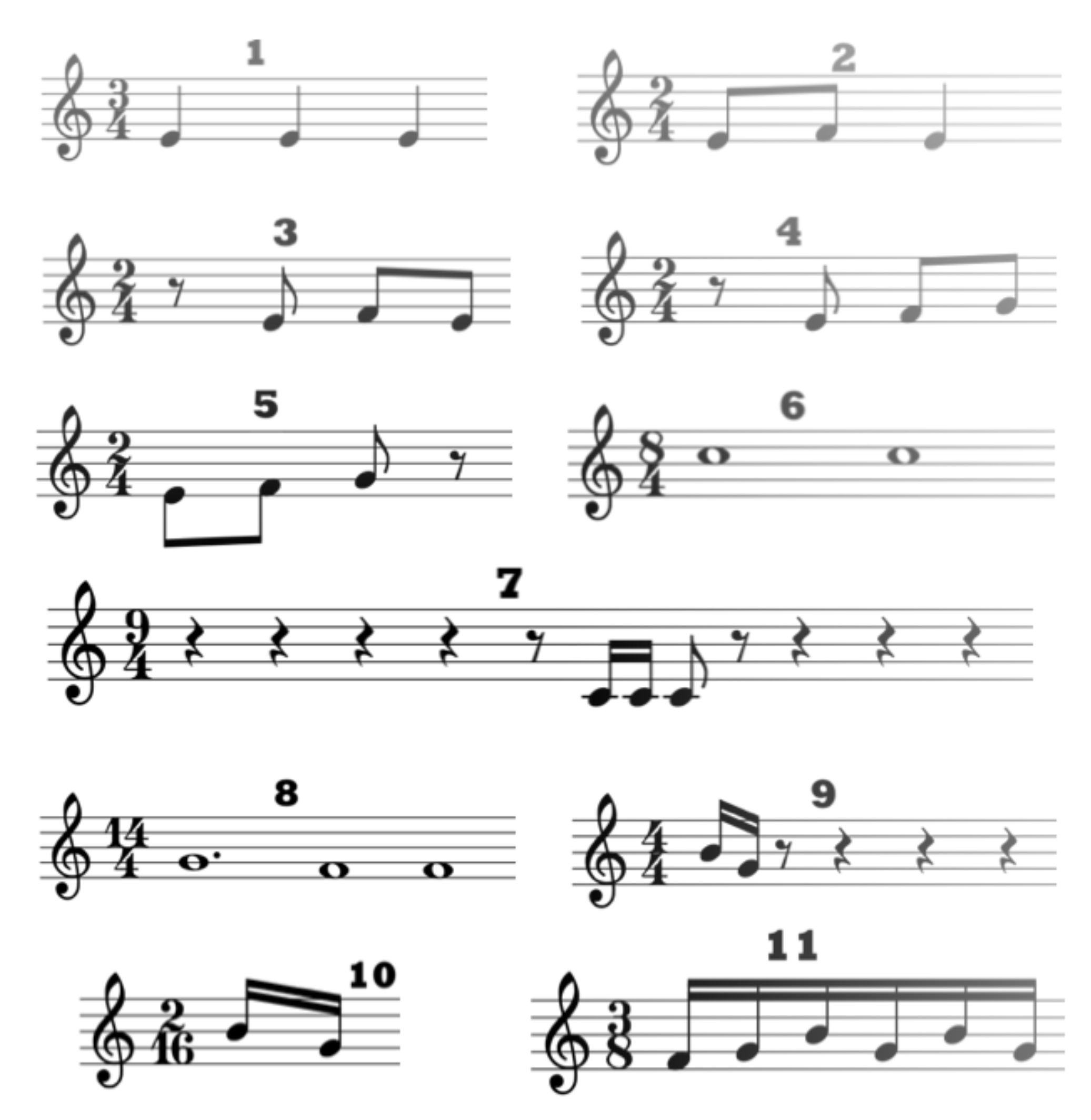
In C’s formal structure is made of 53 melodic excerpts in symbolic (musical) notation. They vary in size, from half beat to up to 32 beats. Each pattern is written in its own bar.
Figure 15 shows the first 11 patterns used in the composition. Some of them are very similar (for example, 2 and 3, or 4 and 5) and change only by a time shift.
The initial idea of Riley was for the musicians to play the excerpts ad libitum (as the musicians pleased, i.e., without a synchronous beat) but that turned out to make the time shifted similar excerpts, like the ones mentioned above, to sound indistinguishable. For that, Steven Reich, another famous composer and personal friend of Riley, suggested that he introduce a time pulse for In C, where the musicians would play the excerpt within a regular pulsation, thus making the difference between time shifted excerpts perceivable as well as generating a rhythmic pattern to the composition.
According to Riley’s original instructions, a group of any number of musicians play 53 excerpts in order, and are free to skip or repeat excerpts. In Riley’s instructions, a musician that reaches the last pattern must play it repeatedly until the music slowly fades out. There is no fixed time for a performance, and the piece ends according to the group’s decision.
In this demonstration, we used the FSMD structure to generate computer performances of In C. For such, we preserved the piece’s core idea of playing patterns, but slightly changed the interaction rules to allow repeating excerpts. This change removes the piece’s “stop condition”, which is originally related to reaching the last excerpt, and, instead, we used the algorithm’s final state a the simulated musician’s stop condition.
Each of the simulated musician is linked to an accumulator, which starts at zero and is used to select the next excerpt to be played. When the state receives a clock pulse and reaches a new state, the new state’s number is added to the accumulator, and this leads to choosing the next excerpt to be played. Each of these additions is followed by a mod-53 operation that prevents the musician to choose an invalid excerpt.
All excerpts are played using a marimba timbre, and at 120 bpm. The excerpts are repeated 4 times. This number was intentionally programmed so that each excerpt’s musical identity is more easily recognized.
This behavior is repeated until the state machine reaches state 5, which is related to the end of the algorithm’s execution. At this point, the musician stops choosing new excerpts. Henceforth, this means that each execution has a defined end.
The simulated musicians’ FSMDs are initialized either with random or pre-defined numbers. Each different initialization leads to a different execution of the piece; henceforth, it is possible to repeat the same execution by using the same initial conditions.
It is important to highlight that musical control using state machines is a common practice, in special in the probabilistic
3.2. Sound parameter control
Modern audio synthesizers are able to produce many sound variations according to their parameters. Many of them allow continuously changing the parameters while playing, which facilitates building sounds that change in time. Commonly, parameter variations either follow a pre-defined path or a random number generator.
The pre-defined paths can be generated using techniques such as linear interpolation and a low-frequency oscillator (LFO), or simply by following a manually drawn curve. They are often easy to control, but can quickly become repetitive and, as a consequence, uninteresting. In contrast, random number generators can create uncorrelated white noise or paths through Markov Chains, which are non-repetitive, but cannot generate repeatable structures.
The FSMDs enables the design of control paths that allow both the exploration and repetition of sound variations, which has the advantages both of the causal and the random control structures. This exploration highly relies on particular characteristics of the implemented algorithm. In this discussion, we use the GCD algorithm implemented in
Section 2.
One possible sound control idea using the algorithm’s properties is to map the internal variables X and Y to synthesizer parameters corresponding to sound properties that change from one point to another using paths that can be explored by the musician. In addition, particular FSM states can be mapped to events that repeat along time. Hence, we simultaneously exploit the internal variables’ tendency to converge and the FSM’s repeating nature.
In this paper, we used this idea to control a simple FM synthesizer followed by a bandpass filter. The FM synthesizer implements the equation:
where
is a time-domain envelope,
f is the waveform frequency (usually related to its pitch),
is a time-domain envelope for the modulating waveform, and
(usually an integer) is the ratio between the modulating and the carrier waveform frequencies.
The FM synthesizer’s envelopes
and
are controlled using non-linear, monotonic transformations of the ratios
and
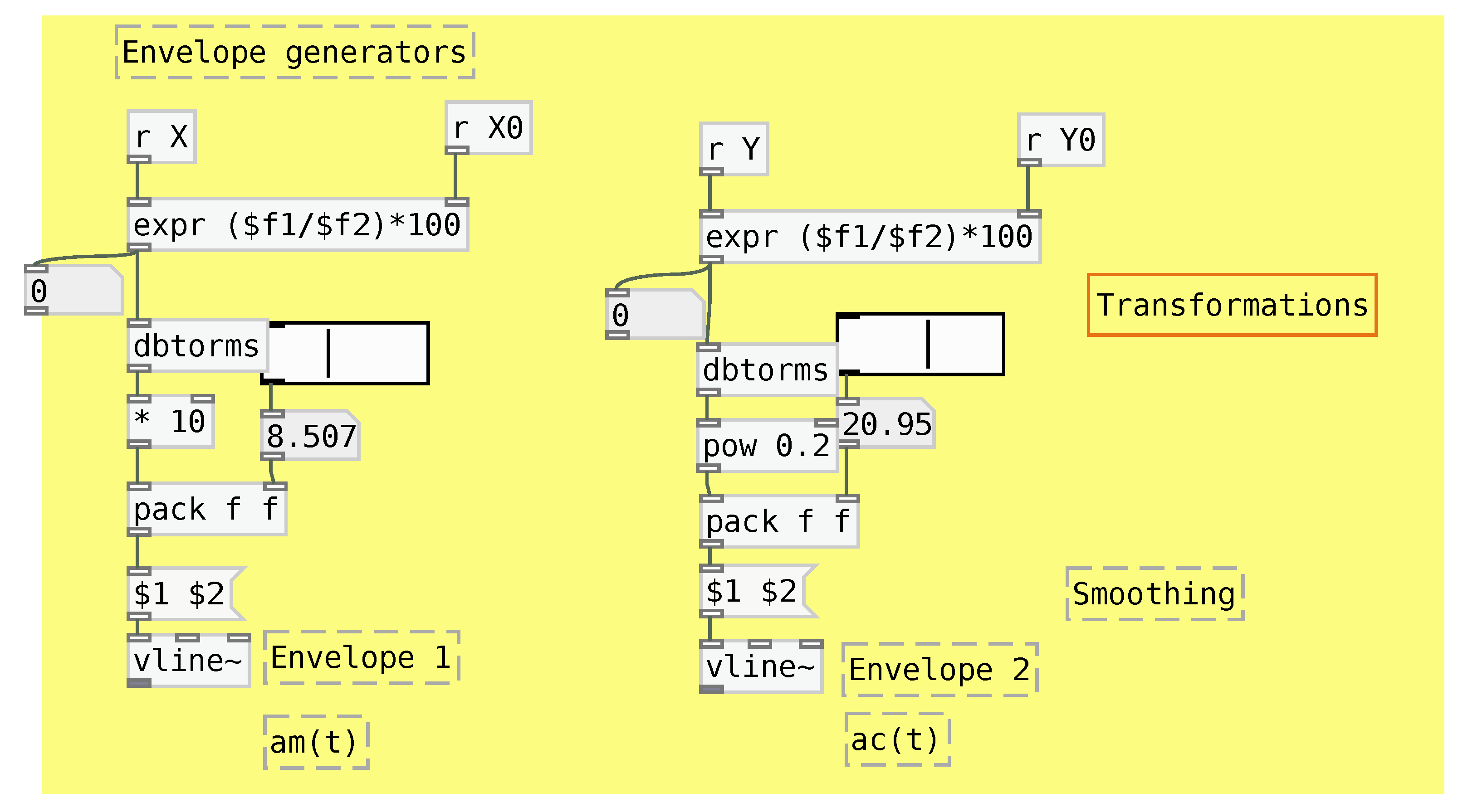
. The transformations used in this work are shown in
Figure 16, and are decided according to aesthetic options. Because of the way the GDC algorithm works, both of those ratios start at 1 and converge to lower values. This allows creating a progression of sound qualities changing from more complex and louder to simpler and quieter throughout time. This progression’s dynamics depends on the algorithm’s starting conditions, its clock frequency, and the transformation applied while mapping.
The output of the FM synthesizer is yielded to a bandpass filter. The filter’s center frequency is controlled by the algorithm’s FSM so that reaching states 1, 3, or 4 leads to shifting the center frequency to pre-defined values. These states were chosen because, in each algorithm’s iteration, state 1 is reached once, followed by either state 3 or 4, that is, these states allow creating repeating patterns along time. The center frequencies changes are smoothed by linear interpolation.
This mapping is summarized in
Table 2 and is demonstrated in
Figure 17. It shows the modulation and magnitude envelopes, as well as the filter center frequencies, throughout time. This specific behavior was generated using X0=265, Y0=61, filter center frequencies for states 1, 3, and 4 respectivelly equal to 280 Hz, 990 Hz, and 460 Hz, and a metronome (clock) period of 400 ms.
As we can see, this mapping strategy displays two different behaviors: the continuous progression towards a final value, and the creation of cycles. These variations are entirely controlled by the musician by changing the initial conditions and , which means that the same behavior can be strictly repeated in different executions of the algorithm. Also, we highlight that the progressions have larger and smaller steps, which is hard to create using simple LFOs or linear envelopes. Such mapping is greatly facilitated by exposing the algorithm’s state machine and its internal variables.
4. Conclusion
This article demonstrates how to use music-domain visual languages to implement algorithms written under the imperative paradigm. Our demonstration uses Pure Data, but the same concepts are immediately portable to Max/MSP. These implementations allow to systematically shift algorithms from the imperative paradigm into the visual paradigm.
The resulting structure consists of a finite state machine coupled with data processing blocks, that is, a Finite State Machine with Datapath (FSMD). Within this structure, the algorithm’s operation can be synchronized with musically-relevant events, such as metronome ticks. This allows its use both to execute the algorithm itself and as controls for algorithmic music.
The advantage of using this type of reasoning is that it can create a large amount of variability and, at the same time, has a predictable behavior during composition. The FSMDs share structures with State Machines that can be used to organize events, and the datapath can be used to generate numbers.
We show two artistic applications for the FSMD. In the first application, the FSMD controls macro-structures of a musical piece as to create several variations based on Terry Riley’s “In C”. In the second one, the FSMD provides intertwined datapath and state-machine changes that allow creating unique sound variations with a FM synthesizer.
Implementing FSMDs in VPLs such as Pure Data an Max/MSP allows effectively exploring a creative space that is deterministic, but complex enough that it does not become uninteresting. As we show, the VPL implementations FSMD structures can either be immediately mapped to musical controls or yielded to further processing stages, which is easily performed with VPLs such as Pure Data and Max/MSP. Henceforth, the structures discussed in this article can foster the exploration of diverse novel musical possibilities and foster a myriad of future artistic work.
Figure 1.
Example patch in Pure Data. Objects receive inputs in their inlets and yield outputs in their outlets. Some objects can be used as buttons, sliders, toggles or number visualizers.
Figure 1.
Example patch in Pure Data. Objects receive inputs in their inlets and yield outputs in their outlets. Some objects can be used as buttons, sliders, toggles or number visualizers.
Figure 2.
Problem with using implicit order of operations in Pure Data. Changing object creation order can change precedence and cause different behavior in the output.
Figure 2.
Problem with using implicit order of operations in Pure Data. Changing object creation order can change precedence and cause different behavior in the output.
Figure 3.
Solution for the execution precedence problem using explicit operation precedence.
Figure 3.
Solution for the execution precedence problem using explicit operation precedence.
Figure 4.
Clock-synchronous operation for subtraction.
Figure 4.
Clock-synchronous operation for subtraction.
Figure 5.
Functional blocks of a FSM.
Figure 5.
Functional blocks of a FSM.
Figure 6.
Bubble diagram for a FSM.
Figure 6.
Bubble diagram for a FSM.
Figure 7.
Pure Data implementation of the FSM, showing the state register (light gray), the input control (orange), and the transition implementation (blue).
Figure 7.
Pure Data implementation of the FSM, showing the state register (light gray), the input control (orange), and the transition implementation (blue).
Figure 8.
Functional blocks of a datapath.
Figure 8.
Functional blocks of a datapath.
Figure 9.
Pure Data implementation of a datapath, highlighting the clock routing schema (light gray), and the datapath (yellow) containing the operation implementations, the operation selection schema and the memory that stores the output variable X.
Figure 9.
Pure Data implementation of a datapath, highlighting the clock routing schema (light gray), and the datapath (yellow) containing the operation implementations, the operation selection schema and the memory that stores the output variable X.
Figure 10.
Finite State Machine with Datapath.
Figure 10.
Finite State Machine with Datapath.
Figure 11.
Clock routing for each of the functional parts of the FSMD.
Figure 11.
Clock routing for each of the functional parts of the FSMD.
Figure 12.
Flowchart for Euclid’s GCD algorithm and corresponding FSMD. States from the FSM are juxtaposed to the corresponding flowchart blocks. Datapath components are shown in yellow.
Figure 12.
Flowchart for Euclid’s GCD algorithm and corresponding FSMD. States from the FSM are juxtaposed to the corresponding flowchart blocks. Datapath components are shown in yellow.
Figure 13.
Clock-synchronous comparator using Pure Data.
Figure 13.
Clock-synchronous comparator using Pure Data.
Figure 14.
Complete Pure Data implementation of the GCD algorithm using a FSMD.
Figure 14.
Complete Pure Data implementation of the GCD algorithm using a FSMD.
Figure 15.
The first 11 musical excerpts of In C, by Terry Riley.
Figure 15.
The first 11 musical excerpts of In C, by Terry Riley.
Figure 16.
Transformations applied to and to generate modulation () and magnitude () envelopes for the FM synthesizer. The envelopes can be smoothed using the horizontal sliders.
Figure 16.
Transformations applied to and to generate modulation () and magnitude () envelopes for the FM synthesizer. The envelopes can be smoothed using the horizontal sliders.
Figure 17.
Demonstration of mapping from FSMD elements to FM synthesizer parameters.
Figure 17.
Demonstration of mapping from FSMD elements to FM synthesizer parameters.
Table 1.
Transition table for a FSM.
Table 1.
Transition table for a FSM.
| Current state |
Input |
Next state |
| S0 |
0 |
S2 |
| S0 |
1 |
S1 |
| S1 |
0 |
S0 |
| S1 |
1 |
S2 |
| S2 |
0 |
S1 |
| S2 |
1 |
S0 |
Table 2.
Relationships between the synthesizer’s parameters, their auditory/musical meanings, and their typical behavior in time.
Table 2.
Relationships between the synthesizer’s parameters, their auditory/musical meanings, and their typical behavior in time.
| Parameters |
Meaning |
Behavior |
| f |
Fundamental frequency (pitch) |
Fixed |
|
Harmonicity and timbre |
Fixed |
| Mapping
|
Sound intensity along time |
Progressions |
| Mapping
|
Timbre complexity along time |
Progressions |
| Filter center frequencies |
Timbre variations along time |
Patterns |
| FSMD clock frequency |
Envelope speed |
Fixed |
