1. Introduction
Time measurements (time-to-digital conversion) [
1,
2,
3,
4] have always belonged to the class of the most demanded measurements since it is reasonable to reduce measurements of many heterogeneous physical quantities to time measurements. As modern methods and instruments for measuring time provide very high accuracy [
5], these technologies are in demand in a wide range of fields and industries [
6,
7]. The most commonly used time measurements are measurements of time intervals (TI) between the start and stop input signals [
8,
9]. For a significant part of the experiments, the object of investigation is the time relations between initialising and secondary events [
10,
11].
In the analysis of measurement errors of time intervals, we assume that the result
Ai of the
i-th measurement is, in general, a random variable and can be represented as a sum of the measured quantity
Ti and the absolute error of its measurement
ai
The absolute measurement error ai can, in turn, be represented as the sum of the random Δ
ir, accuracy Δ
is and offset Δ
c components of the total error [
12], therefore:
The random error (or precision error) Δir has an unpredictable value and represents the scatter of the measurement results due to the influence of noises of different origins.
The accuracy error is determined by the repeatability of its value from measurement to measurement. However, the value of this error Δis itself depends on several parameters. The peculiarity of the accuracy error in TI measurement is its multiplicative character, i.e. the value of Δis is proportional to the duration of the measured TI.
The offset error is determined by the difference between the delays of the start and stop channels and is additive. Its value Δc is offset for a particular meter. The offset error can be determined and used to correct the measurement results accordingly.
Suppose the task is to test a meter. In that case, the value of T
i in (1) is generally unknown since the source (generator) of input signals possesses its errors (Accuracy, Offset, Jitter). Ti can be represented as the sum of the generator set value T
g, generator accuracy error Δ
isg, generator constant error Δ
cg and jitter of the TI generator Δ
irg. Therefore, the general equation of the measurement result is as follows:
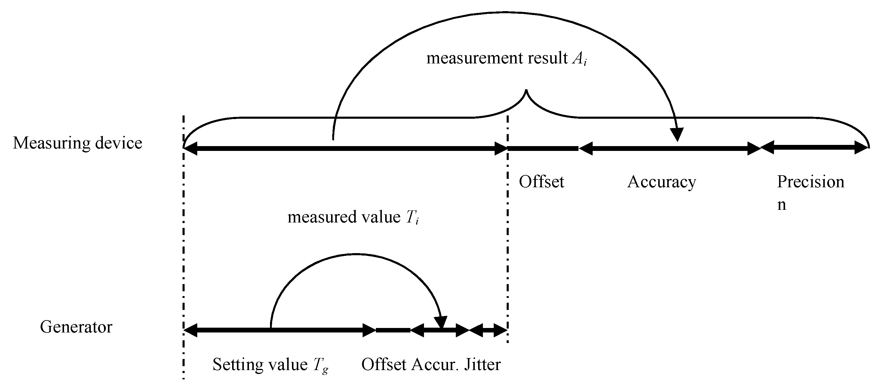
A graphical interpretation of the generation and measurement errors is illustrated in
Figure 1.
The accuracy error Δis in the TI measurement is determined by the stability level of the clock generator (CG) of the meter and is caused by the fact that the period F of the CG differs from the nominal value F0 by τ. The value of τ is not constant and depends on four factors: changes in ambient temperature, the value of the initial deviation from F0, variations in the generator supply voltage and ageing of its components.
In the specifications of a CG, the maximum value of its relative stability is
Kmax, defined as ratio
Kmax=±τ
max/F0, where τ
max takes into account all destabilising factors. According to the methods of minimising the influence of destabilising factors, CGs are divided into stability classes [
13,
14]: standard XO (Crystal Oscillator), termo-compensated TCXO (Temperature Compensated Crystal Oscillators), thermo-stated OCXO (Oven Controlled Crystal Oscillators), microprocessor-corrected MCXO (Microprocessor Corrected Crystal Oscillator), and atomic standards.
Reducing the accuracy error is relatively easy to achieve by using high-end CG in the meter. However, for specific applications (e.g., space electronics), such a solution is not always feasible due to the high cost of high-class CGs, as the main cost component of space-level CGs are the testing procedures. In this paper, the problem of significant reduction of the accuracy error without increasing the CG class of the TI meter is solved.
2. Estimation of Accuracy Error
When measuring time intervals, the result of measurement Ai is proportional to the period of CG F, which determines the multiplicative nature of the accuracy error, and its value Δs increases proportionally to the duration of measured TI. The maximum value of accuracy error Δsmax is usually the parameter of the meter, which can be estimated based on the certificate value Kmax for the applied CG and Amax value, corresponding to the upper limit of the range of measured TI durations: Δsmax= Kmax·Amax.
The experience shows that the Kmax value of a particular CG for the specific temperature conditions of its application can be much less than the value taken from its specifications data. Respectively, the real value of Δsmax can also be several times less. Therefore, the first step in reducing the accuracy error is to estimate the Δsmax value of a particular CG meter.
Evaluation of
Δsmax of a particular TI meter is based on measurement and accumulation of an array
[A] of
n results of the TI measurement (
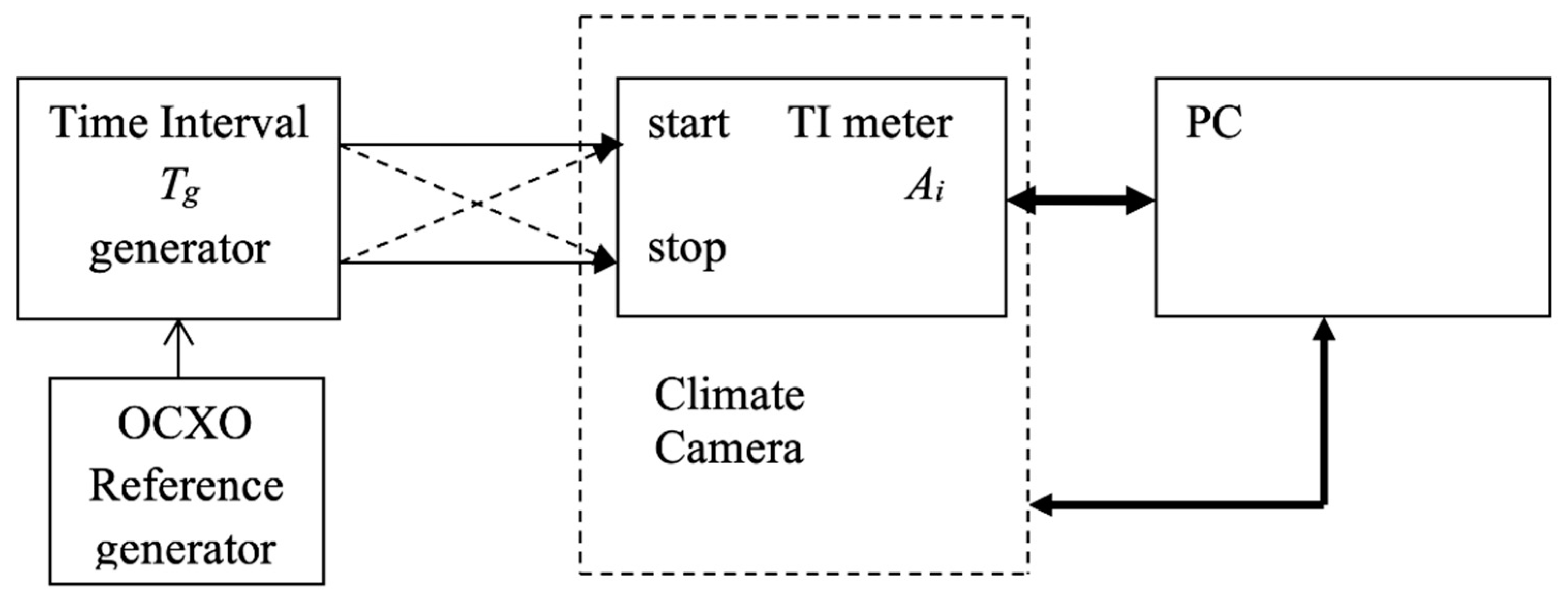
Figure 2) for the case of measuring input TI of maximum duration
Tgmax when the ambient temperature
t° changes in the operating temperature range of the meter. Based on (2), it can be assumed that the average value of the array of measurement results at temperature
t° will be:
In this case, we assume zero values of the meter’s random error and the TI oscillator’s jitter. The influence of the accuracy error of the generator
Δsg included in this expression can be neglected if the stability of its CG is 1-2 classes higher than the CG stability of the TI meter under study. Thus
Figure 2 shows the use of an external OCXO (reference oscillator). In this case, expression (3) is simplified:
Equation (4) used to evaluate the accuracy error Δt°c is complicated due to the presence of unknown error constants Δcg and Δc in the expression. The value of Δc is determined by the difference in delays for the start and stop inputs of the TI meter. In turn, Δcg is determined by the difference in delays in the TI meter start and stop signal generation circuitry and the difference in the lengths of the connection wires.
It is possible to estimate the values of Δ
cg and Δ
c when two conditions are met. Firstly, the TI must be measured with a minimum duration of
Tgmin, which allows for omitting the accuracy errors of the generator Δ
sg and the measurer Δ
s, then:
Secondly, additional measurements are required when the wires are cross-connected to the meter inputs (shown in dashed in
Figure 2), and the sign of inter-channel delay of the TI generator is changed. In this case, a system of equations can be formulated:
Estimation of the error constant of the meter relative to its inputs Δ
c is an independent value, but at the same time, it provides the capability for estimation of Δ
t°s:
While testing the meter in a climate chamber within the meter’s operating temperature range (
Figure 2), a dependence of Δ
t°s on ambient temperature changes
t° can be derived by TI measurement of maximum duration T
gmax. The graphical representation provides a capability to estimate the value of Δ
smax for a particular TI meter and the actual stability of its clock generator K
max=±Δ
smax/T
gmax.
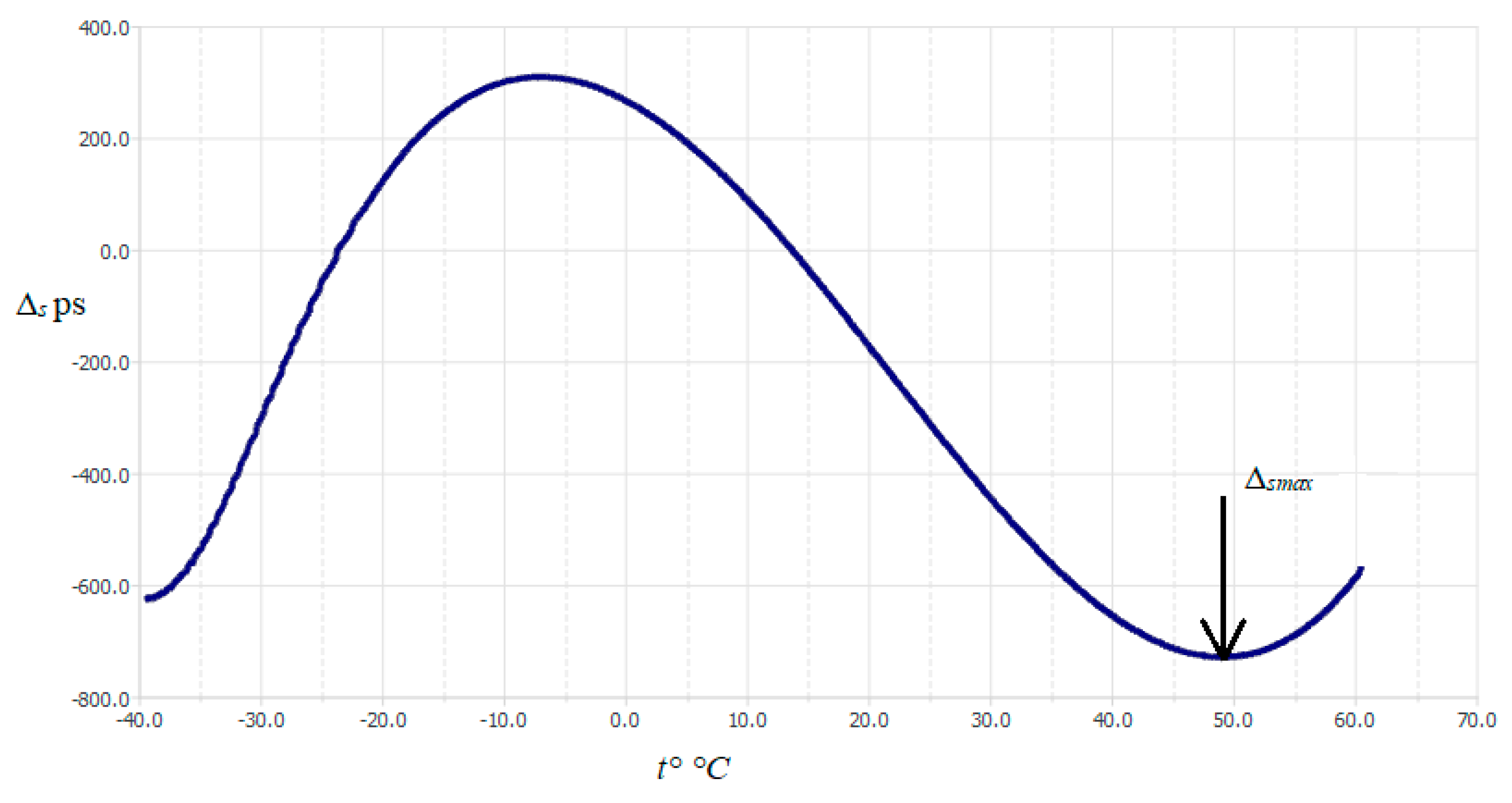
Figure 3 shows an example of the plot of change of Δ
s as a function of temperature for a TI meter with a standard XO class clock generator (according to its specification K
max=±50 ppm). The dependence character in the operating temperature range of the meter (-40°C ÷ +60°C) is of a pronounced non-linear nature and corresponds to the frequency-temperature characteristics of quartz AT-slice plates [
5].
Based on
Figure 3, Δ
smax=740 ps and T
gmax=134 µs, hence the estimate of K
max=±740·10
-12/134·10
-6=5.5-10
-6=±5.5 ppm. The estimation of K
max obtained in this way is underestimated since it does not take into account the influence of instability of the generator supply voltage and the ageing of its components. Nevertheless, the difference between the specification listed and the actual component's parameter values is sufficient.
3. Compensation for Accuracy Error
The investigation of the dependence of the accuracy error value Δs on the temperature for a particular CG provides the capability to perform a procedure for offsetting the influence of the accuracy error on the measurement result.
The compensation procedure is based on a special calibration, during which a series of high-precision TI measurements are carried out under changing ambient temperature t°. This is done by determining the average values of the TI measurement Āt° and the accuracy error Δt°s for the current temperature t° according to (5). The correction factors Kt°=Δt°s/Āt° and the corresponding temperature calculated from this data are recorded as a table of Kt° and t° values in the memory of the meter or processing computer.
Considering the non-linear nature of the relationship between the accuracy error and temperature (
Figure 3), the choice of a table to record the relationship between the correction factors and temperature is the simplest method, although it requires memory resources.
Several conditions have to be met during calibration: the CG class of the TI generator must be higher than the CG class of the measured (compensated) meter, the results of the calibration measurements must be averaged to increase the accuracy of the table, and the Tgmax value must correspond to the maximum working range of the TI durations to be measured.
In general, calibration should be carried out under the real conditions of the meter’s use or its equivalent. For example, if we are talking about space applications, then calibration must be carried out under thermo-vacuum conditions.
To implement the procedure for compensating for the accuracy error under actual measurement conditions, it is essential to monitor the current temperature t°. The algorithm for compensation of the i-th measurement result consists of extracting from the table the Kt° coefficient corresponding to the temperature t° at the time of measurement and calculating the compensated measurement result At°i: comAt°i=At°i(1-Kt°).
In a general case, the measurement result A
t°i contains both an accuracy error and a constant error Δ
c, so comA
t°i°=(A
t°i-Δ
c)(1-K
t°).
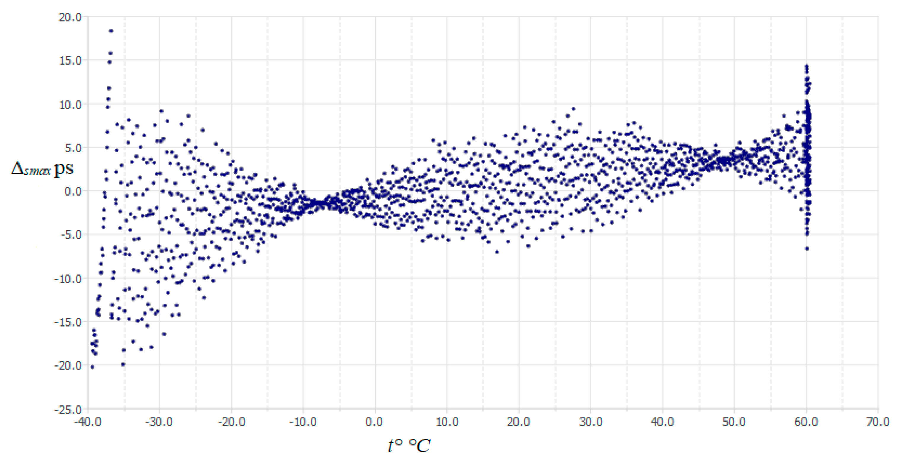
Figure 4 represents the dependence of the accuracy error Δ
s on the temperature after the compensation of the accuracy error shown in
Figure 3. The value of Δ
smax decreased from 740 ps to 20 ps, and the equivalent stability of CG, in this case, reaches a value of ±0.15 ppm.
The compensation procedure also has its limitations since it does not consider the influence of instability of TG supply voltage and the ageing of its components.
As in the proposed solution, a variant of accuracy error minimisation implying a pre-calibration procedure is presented in [
15]. This option is based not on the correction of measurement results but on microprocessor correction of frequency of VCXO class CG, the frequency of which is controlled by DAC voltage.
The microprocessor performs the calibration by the user. As a result of this procedure, the coefficients of the 4th-degree polynomial are determined and stored. This coefficient is used to calculate the DAC codes, which compensate the VCXO frequency deviation for the current temperature value t°. The CGs based on this principle belong to the CCXO (Coefficient Corrected Oscillator) class and can ensure the stability of the CG at the level of 0.1÷0.3 ppb. In its application, there is no need to manually correct measurement results, but the cost of such CGs is high, and at this time, it is not manufactured for the space-level ready version.
4. Conclusions
The accuracy error at measuring time intervals (IT) is determined by the relative stability of the clock generator (CG) used in a meter and the duration of the measured time interval. The discussed method of accuracy error compensation eliminates the dependence of accuracy error on the duration of measured TI. It reduces to a minimum the influence of such destabilising factors as changes in ambient temperature and initial deviation of the clock frequency from its nominal value.
To implement the compensation method, three procedures have been developed: a procedure for registering an accuracy error, a calibration procedure in which a correction table is generated, and a procedure for correcting measurement results in real conditions of the meter’s application. The main expenditures of implementing the method consist primarily in correctly conducting the meter’s calibration, and hardware support for temperature monitoring and performing relatively straightforward computational operations is also required. The main costs of the method implementation primarily consider the correct calibration of the meter, as well as the required hardware support for temperature monitoring and relatively simple computational operations performance.
Experimental validation of the method demonstrated that an equivalent instability of ±0.15 ppm can be achieved for a standard class XO meter (specification instability of ±50 ppm), which reduces the accuracy error to the equivalent degree. The accuracy error compensation procedure has its limitations related to the replicability of the field conditions in which the calibration procedure has been performed.
5. Patent
The patent application of the Republic of Latvia LVP2023000010 has been filed (filing date: 02.02.2023) in perspective of the study conducted and the consequent conclusions.
Author Contributions
For research articles with several authors, a short paragraph specifying their individual contributions must be provided. The following statements should be used “Conceptualization, V.B. and A.L.; methodology, V.B. and Vs.S.; software, V.K.; validation, V.B., Vs.S. and V.K.; formal analysis, V.B.; investigation, V.B., Vs.S. and V.K.; resources, V.L.; data curation, V.S.; writing—original draft preparation, V.B., V.L. and A.L.; writing—review and editing, V.B., V.L. and A.L; visualisation, V.S.; supervision, V.B.; project administration, A.L.; funding acquisition, A.L. and V.K. All authors have read and agreed to the published version of the manuscript.”
Funding
This work has been supported by the European Regional Development Fund, project no. 1.1.1.1/20/A/104” Multichannel picosecond precision time-tag system with amplitude measurements capability for satellite laser ranging”
Conflicts of Interest
The authors declare no conflict of interest.
References
- Maichen, W. Digital Timing Measurements: From Scopes and Probes to Timing and Jitter; Frontiers in Electronic Testing; Springer US: Boston, MA, 2006; Vol. 33; ISBN 978-0-387-31418-1. [Google Scholar]
- Alahdab, S.; Mäntyniemi, A.; Kostamovaara, J. Review of a Time-to-Digital Converter (TDC) Based on Cyclic Time Domain Successive Approximation Interpolator Method with Sub-Ps-Level Resolution. In Proceedings of the 2013 IEEE Nordic-Mediterranean Workshop on Time-to-Digital Converters (NoMe TDC); October 2013; pp. 1–5. [Google Scholar]
- Tancock, S.; Rarity, J.; Dahnoun, N. Developments in Time-to-Digital Converters during 2020. In Proceedings of the 2021 7th International Conference on Event-Based Control, Communication, and Signal Processing (EBCCSP), June 2021; pp. 1–5. [Google Scholar]
- El-Hadbi, A.; Elissati, O.; Fesquet, L. Time-to-Digital Converters: A Literature Review and New Perspectives. In Proceedings of the 2019 5th International Conference on Event-Based Control, Communication, and Signal Processing (EBCCSP); May 2019; pp. 1–8. [Google Scholar]
- Johansson, S. Parallel, Multi-Channel Frequency & Time Measurements, with Picosecond Resolution. Sensors & Transducers 2021, 254, 1–9. [Google Scholar]
- Gan, Q.; Wang, W.; Liu, Y.; Liu, W. Study on the High Precision Time-Interval Measurement System Based on FPGA and TDC_GP22. In Proceedings of the 9th International Symposium on Test Automation & Instrumentation (ISTAI 2022), November 2022; Vol. 2022. pp. 380–382. [Google Scholar]
- Li, X. The Application Research Based on High-Precision’s Measurement Method of Time Interval. In Proceedings of the 2011 International Conference on Multimedia Technology; July 2011; pp. 3713–3715. [Google Scholar]
- Szplet, R.; Kwiatkowski, P.; Jachna, Z.; Różyc, K. An Eight-Channel 4.5-Ps Precision Timestamps-Based Time Interval Counter in FPGA Chip. IEEE Transactions on Instrumentation and Measurement 2016, 65, 2088–2100. [Google Scholar] [CrossRef]
- Zhao, J.; Zhao, Z.; Fu, L. Research on the High Resolution Precision Time-Interval Measurement Methods. Procedia Engineering 2017, 174, 1257–1261. [Google Scholar] [CrossRef]
- Raina, H.; Sankannawar, P.; Sawant, V.; More, J. Implementation of Multi-Channel Time-to-Digital Converter Using FPGA. In Proceedings of the 2022 2nd International Conference on Intelligent Technologies (CONIT); June 2022; pp. 1–6. [Google Scholar]
- Nissinen, J.; Nissinen, I.; Kostamovaara, J. Integrated Receiver Including Both Receiver Channel and TDC for a Pulsed Time-of-Flight Laser Rangefinder With Cm-Level Accuracy. IEEE Journal of Solid-State Circuits 2009, 44, 1486–1497. [Google Scholar] [CrossRef]
- Crowder, S.; Delker, C.; Forrest, E.; Martin, N. Introduction to Statistics in Metrology; Springer Nature, 2020; ISBN 978-3-030-53329-8.
- Rutkowski, R. Crystal Oscillators: The Beginners Guide (OCXO, TCXO, VCXO, Clocks) Available online:. Available online: https://blog.bliley.com/quartz-crystal-oscillators-guide-ocxo-tcxo-vcxo-clocks (accessed on 4 September 2022).
- Quartz Crystal Cuts: AT, BT, SC, CT. » Electronics Notes Available online:. Available online: https://www.electronics-notes.com/articles/electronic_components/quartz-crystal-xtal/crystal-resonator-cuts-at-bt-sc-ct.php (accessed on 4 September 2022).
- Vectron International Application Note. Coefficient Corrected Oscillator - CCXO. 2014.
|
Disclaimer/Publisher’s Note: The statements, opinions and data contained in all publications are solely those of the individual author(s) and contributor(s) and not of MDPI and/or the editor(s). MDPI and/or the editor(s) disclaim responsibility for any injury to people or property resulting from any ideas, methods, instructions or products referred to in the content. |
© 2023 by the authors. Licensee MDPI, Basel, Switzerland. This article is an open access article distributed under the terms and conditions of the Creative Commons Attribution (CC BY) license (http://creativecommons.org/licenses/by/4.0/).


