1. Introduction
Emerging applications like water quality monitoring [
1], off-shore asset monitoring [
2], bio-diversity monitoring [
3], oil field exploration [
4], bio-geochemical process exploration [
5], and large-scale deployment of acoustic modems and their highly efficient computing and denoising capabilities [
6], have driven considerable time, financial and intellectual investment from both industry and academia over the past few years towards developing feasible underwater acoustic communication (UWAC) systems. However, the complex nature of water, slow propagation speed of acoustic waves through water, limited bandwidth availability, complex noise sources and delay-Doppler effects, make it way more challenging to design and deploy a reliable UWAC system, as compared to traditional terrestrial radio systems [
7,
8]. The only way forward is to design dedicated signal processing algorithms and network protocols for UWAC scenario which are validated across a variety of scenarios.
Running actual sea, river or lake-experiments is both financially and logistically challenging [
9]. Border security protocols of multiple nations sharing a water-body sometimes makes it almost impossible to run trials, particularly in the design stage. Therefore, it is absolutely crucial for system engineers to test their design using controllable yet realistic and comprehensive emulator platforms. Channel emulator platforms can enable designers to benchmark performances of different algorithms across a wide range of parameters, and obtain large samples of how the system performs and evolves over time via thorough empirical evaluation [
10]. Once the robustness of the designed system has been synthetically validated, experimental demonstrations can be arranged for a specific environment with a much lower time, financial and logistic commitment.
Developing channel emulators for UWAC environment is extremely challenging as there is no typical underwater environment. The water characteristics vary with depth, salinity, density, geographical locations. The acoustic signal suffers from varying attenuation, absorption, delay, Doppler effects and noise effects with varying underwater characteristics, and sea-surface and sea-bottom contours [
11,
12]. Therefore, instead of separately characterizing each environment parameters and key affecting factors, we develop a mathematical model using the physics of the medium and acoustic signal propagation to map the interaction between the aquatic medium and the travelling signal.
Several UWAC channel modelling software and platforms have been developed over the years to realistically represent different UWAC communication scenarios. A very popular Open Source platform is BELLHOP [
13] that uses beam tracing to emulate acoustic pressure fields in a particular underwater environment. Another widely used one is the Ulrick model [
14] that calculates distance-related spreading loss and frequency-related absorption loss over UWAC links. Other UWA network simulators like DESERT [
15], SUNSET [
16], and WOSS [
17] also provide researchers with valuable insights on the UWAC environments. However, there is no single unifying platform taking the flow of acoustic signal through any aquatic environment to draw insights on how the signal interacts with the environment, what changes the signal experience over time and distance, and how those changes impact the overall design of the communication system.
The primary contribution of this paper is to combine mathematical modelling of how acoustic signal travels through water and sum-of-sinusoids (SOS) [
18]-based generation of channel samples in a generalized yet tractable channel emulator platform. The emulator is capable of characterizing key aspects of UWAC channel, like, signal amplitude profile, attenuation, propagation loss and delay, Doppler spread and shift, which are critical for designing signal processing techniques, networking protocols and network topology extraction. Specifically, we,
Combine concepts of damped harmonic classical oscillators [
19], Milne’s oscillator [
20], and acoustic wave equations to formulate a mathematical model for propagation of acoustic signal through underwater environment.
Integrate outputs of the mathematical model with wide sense stationary uncorrelated scattering (WSSUS) and SOS-based models for synthetic generation of channel impulse response, signal amplitude and phase change profiles, and Doppler frequencies and Doppler power spectral profile.
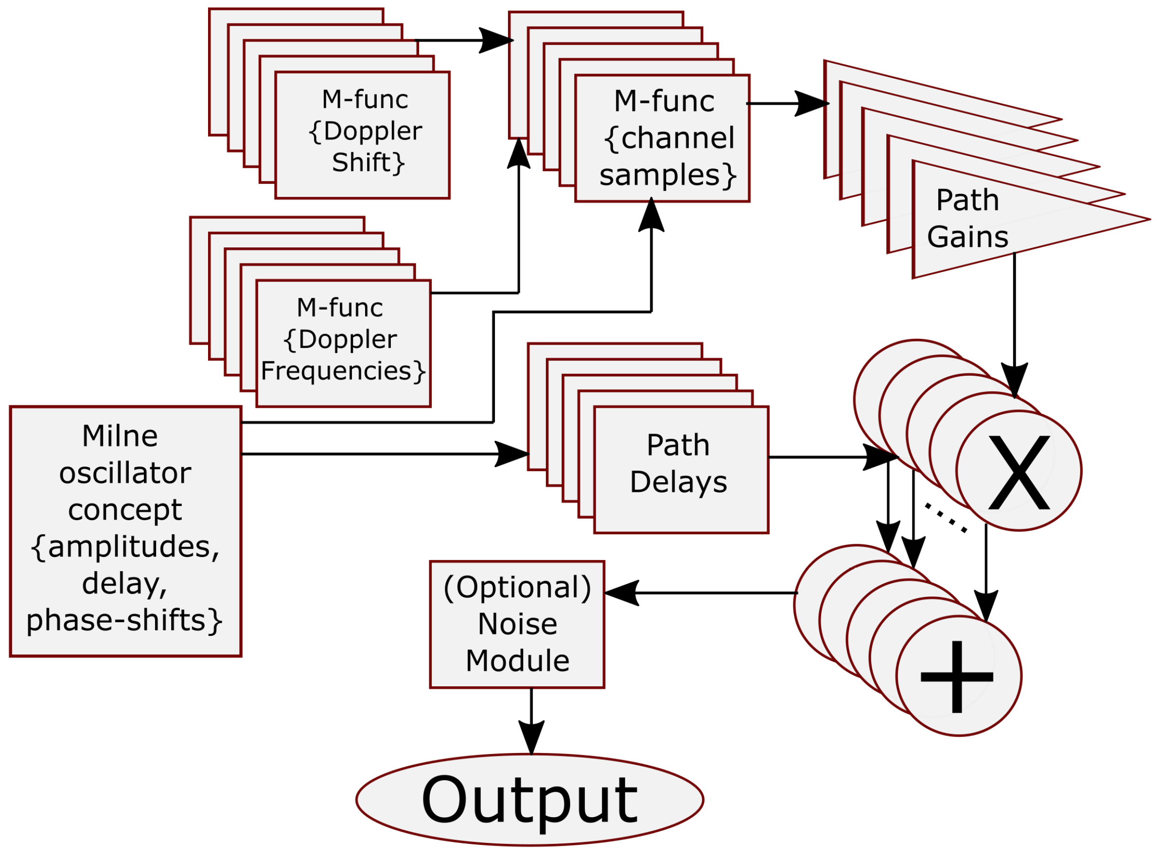
Develop a Simulink-based channel emulator platform that incorporates the oscillator-based mathematical model and WSSUS-based channel sample generation.
Using the developed channel emulator platform, demonstrate i) snapshots of channel samples for different scenarios and parameters and ii) performance of two example communication systems - a) Differential M-ary Phase Shift Keying (DMPSK)- Orthogonal Frequency Division Multiplexing (OFDM) system with -rate Turbo coding for single-transmit-single-receive scenario; b) DMPSK-OFDM system with -rate Turbo coding for multiple-transmit-multiple-receive scenario.
3. Designing the UWAC Channel Emulator
Linear Time Varying (LTV) systems are primarily used to characterize UWAC channels owing to their time-varying nature and varying environmental factors affecting the flow of acoustic signal through water. When an acoustic signal travels through water, the signal gets reflected by the surface and bottom of the sea resulting in multiple delayed versions of transmission rays or path bundles. If we have
Q number of distinct reflected and refracted rays (echoes) with amplitude
(
) represents determinant of a matrix) and delays
, then the propagation channel with multiple information paths can be mathematically represented as,
where
is the fading parameter characterizing small scale variations with each path bundle. If
is stationary in time, then we can use the time correlation function to derive the statistical description of
,
where
denotes the Expectation operation and ∗ denotes the complex conjugate. In this case, Fourier Transform of
yields the channel Doppler spectrum,
which can be approximated by the stretched exponential distribution. In (
20),
denotes discrete Fourier transform (DFT),
represents Doppler frequencies,
represents how closely the Doppler power spectrum matched to the stretched exponential function and
denotes the stretching exponent. Time-domain auto-regressive memory process based generation of stretched exponential spectrum is neither practical nor accurate in representation. This is because,
has no closed form, and its Fourier transform is no longer exponentially distributed. Instead, in our developed platform we generate random processes directly from the Doppler spectrum using the sum-of-sinusoids (SoS) model.
The delay power spectrum of the channel and its frequency correlation function can be expressed as,
and
respectively, assuming stationarity and uncorrelatedness. The difference between the initial frequency
f and the final frequency
defines the amount of frequency correlation. Owing to the uncorrelated nature of
, it is possible to calculate each path delay separately. We can then modify (
22) in the delay domain to obtain,
and from (
23), we can obtain
, the delay-domain scattering of the
qth path with respect to Doppler spectrum.
Reflections due to surface, bottom, surface-bottom and surface-bottom-surface combination gives rise to different sets of reflected paths with a range of Rician
K-factors. We will therefore use the SoS assumption for generating channel samples with amplitudes that are Rician-distributed. We consider the wide sense stationary uncorrelated scattering (WSSUS) assumption here and therefore we can represent channel samples
to formulate the SoS model,
with time
t sampled into intervals of
,
L number of path bundles for each tap, uniformly distributed random phases
over the interval
, initial phase
and
L Doppler frequencies
within each tap. In (
24),
K is the Rician
K-factor depending on the ratio of signal power over the direct path to that over scattered paths and the direct line-of-sight (LoS) path acquires a Doppler frequency of
. It is evident that
L sets of Doppler frequencies
can be selected from Jake’s spectrum such that these
s, in turn, can be used to generate (
24) and the probability density function (pdf) of the range of
can be expressed as,
From (
25), the values of
can be formulated using the inverse transform sampling lemma [
21]. The inverse transform sampling lemma states that if the distribution function of input
X is given by
, the cumulative distribution function (cdf),
will be uniformly distributed over the range
. Consequently, input samples can be generated using
where
is uniformly distributed over the range
, where
F denotes the distribution function. Using the above concept, the cdf of the Doppler frequencies
can be expressed as,
where the obtained
s are stretched exponentially distributed and mod refers to the modulo operation,
W represents the Product-Log or Lambert-
W function. It is worth-mentioning here that the ’modulo’ operation returns the remainder after division of
by 1 and we consider that
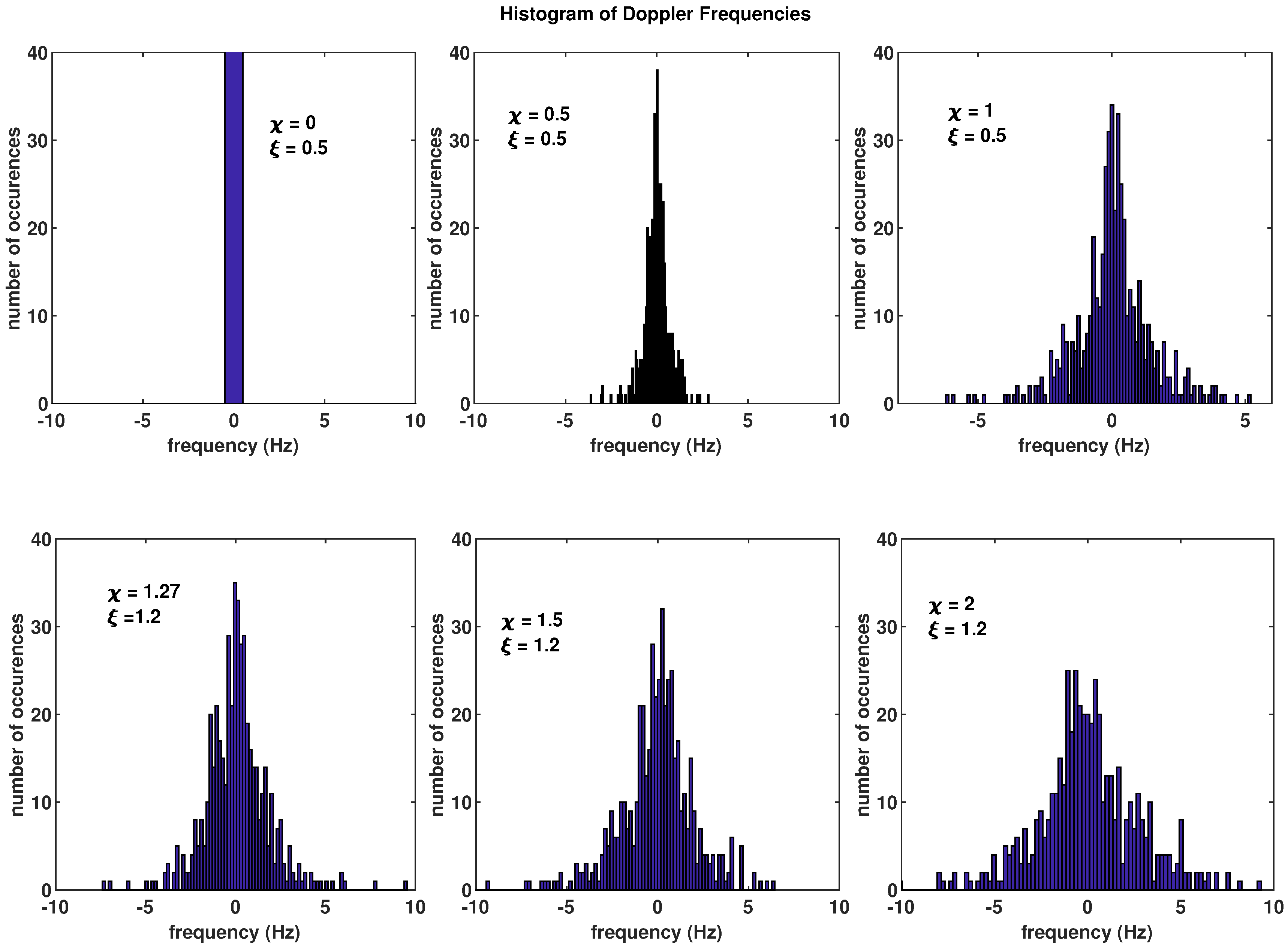
. A range of histograms of the
s using (
25) and (
26) is plotted in
Figure 3. Using the discrete frequency-selective channel model, the channel impulse response is given by,
where
represent the fading coefficients corresponding to the originally formulated Milne energy associated with each path bundle, and
represents the delay function quantifying the delay experienced by the
qth path . The delay is represented using the
function as we are trying to model the infinite bandwidth system. In terms of system implementation, an infinite bandwidth system needs transmit and receive filters for effective functioning.
Here, we consider a combination of pulse-shaping transmit filter with impulse response
, the propagation channel
and a matched receive filter, to represent a communication system with complex transmit samples
and output signal
. If
is sampled at intervals which are multiple of
T or sampling time
, the overall communication system embodies a discrete linear time-varying filter constituted of
filter taps. Therefore, such a communication system can be exemplified as a tapped delay line filter model. Towards this end, the filter taps,
, can be generated using digital filtering that has a sampling rate capable of modelling usable channel bandwidth for the channel model of (
27).
These filter taps can be characterized by the following equation,
where
is the initial delay and
are average power levels observed over
Q path bundles. If we want to account for the drift velocity
v between the transmit and the receive terminals in an underwater environment, (
28) gets modified to,
where
,
m/s, and
a is the Mach number.
The concept of Mach number is introduced to represent the time-stretching or Doppler shift i.e., the time period
t expands to
. Now, here
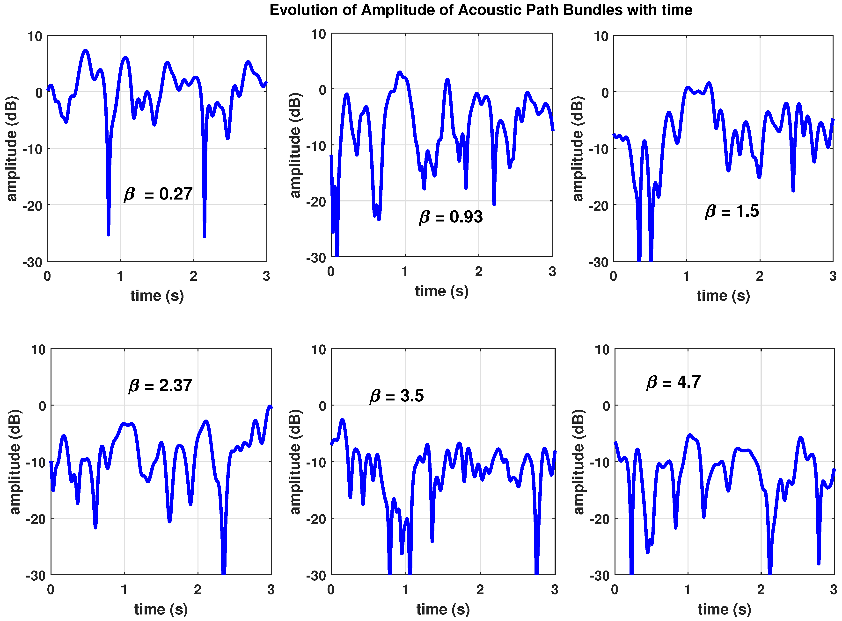
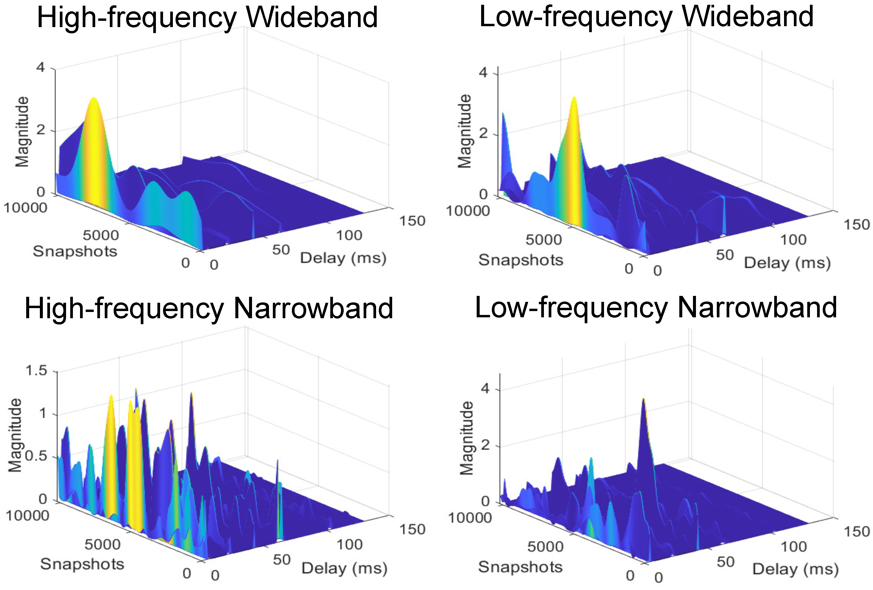
N is an important factor in the emulator design as it offers a trade-off between computational complexity and model stationarity. A sample set of trajectories generated over a 3-second interval and
,
,
is presented in
Figure 4. We have also included the corresponding Doppler frequency distribution, Doppler power spectrum and temporal coherence in
Figure 4. It is noted here that seldom practical measurements from trial match the WSSUS assumption for underwater propagation channels. However, in our work, we derive the amplitude of paths/echoes of travelling sound waves, delays experienced and other relevant parameters directly from the concept of physics. These concepts are directly derived from mathematical description of how acoustic waves travel through water and how water interacts and influences that flow of acoustic waves. Therefore, it is possible to identify time periods and bandwidth within which the WSSUS assumption is valid [
22]. Accordingly, it is possible to determine an observation time
, over which, the auto-correlation function of
,
is stationary with constant mean value. Also, we can define an observation bandwidth
, within which, the frequency auto-correlation function,
is stationary.
Special Note on Measurement Campaign
We are currently in the process of collecting UWAC channel measurements in coastal and estuarine environments around Ireland and Wales as part of the project STREAMS
1. In STREAM, we are deploying underwater sensors to gather valuable information on temperature, rainfall, wind, marine nutrients, oxygen content and phytoplankton abundance. However, as a part of deploying underwater sensor networks, we are also collecting propagation channel information in the underwater environment for communication among acoustic sensors using acoustic signals. This measurement campaign is ongoing at the time of writing this paper and therefore could not be reported here. In future, the model and emulator developed in this paper will be validated against the measurements collected in the STREAM project.
