Submitted:
22 March 2023
Posted:
23 March 2023
You are already at the latest version
Abstract
Keywords:
1. Introduction
2. Materials and Methods
2.1. Synthesis of unsubstituted and YCl3-substituted CsPbI3 NCs
2.1.1. Cesium Oleate Preparation
2.1.2. Synthesis of CsPbI3 NCs
2.1.3. Synthesis of YCl3:CsPbI3 NRs
2.1.4. Purification
2.2. LED Fabrication
3. Results and Discussion
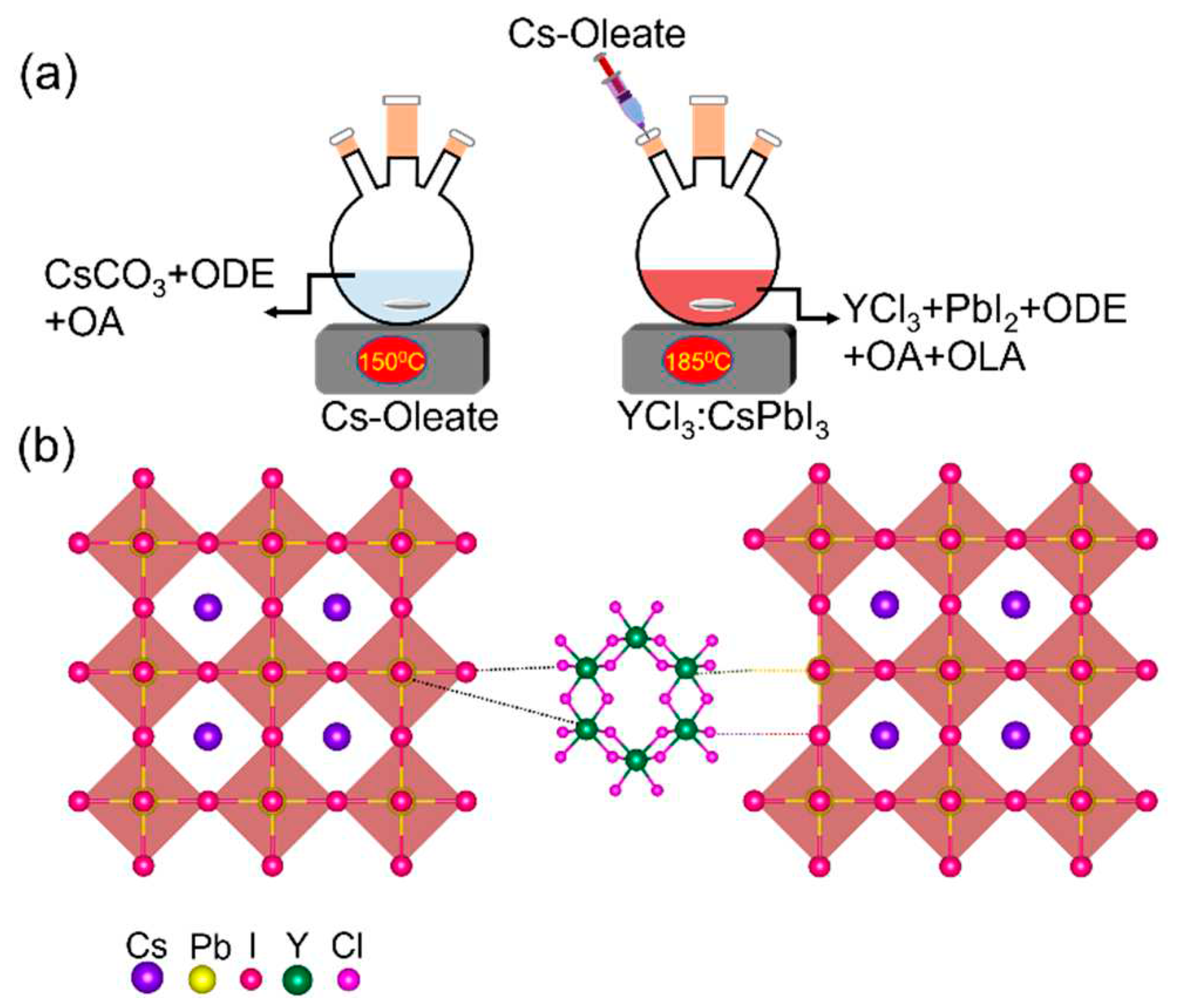
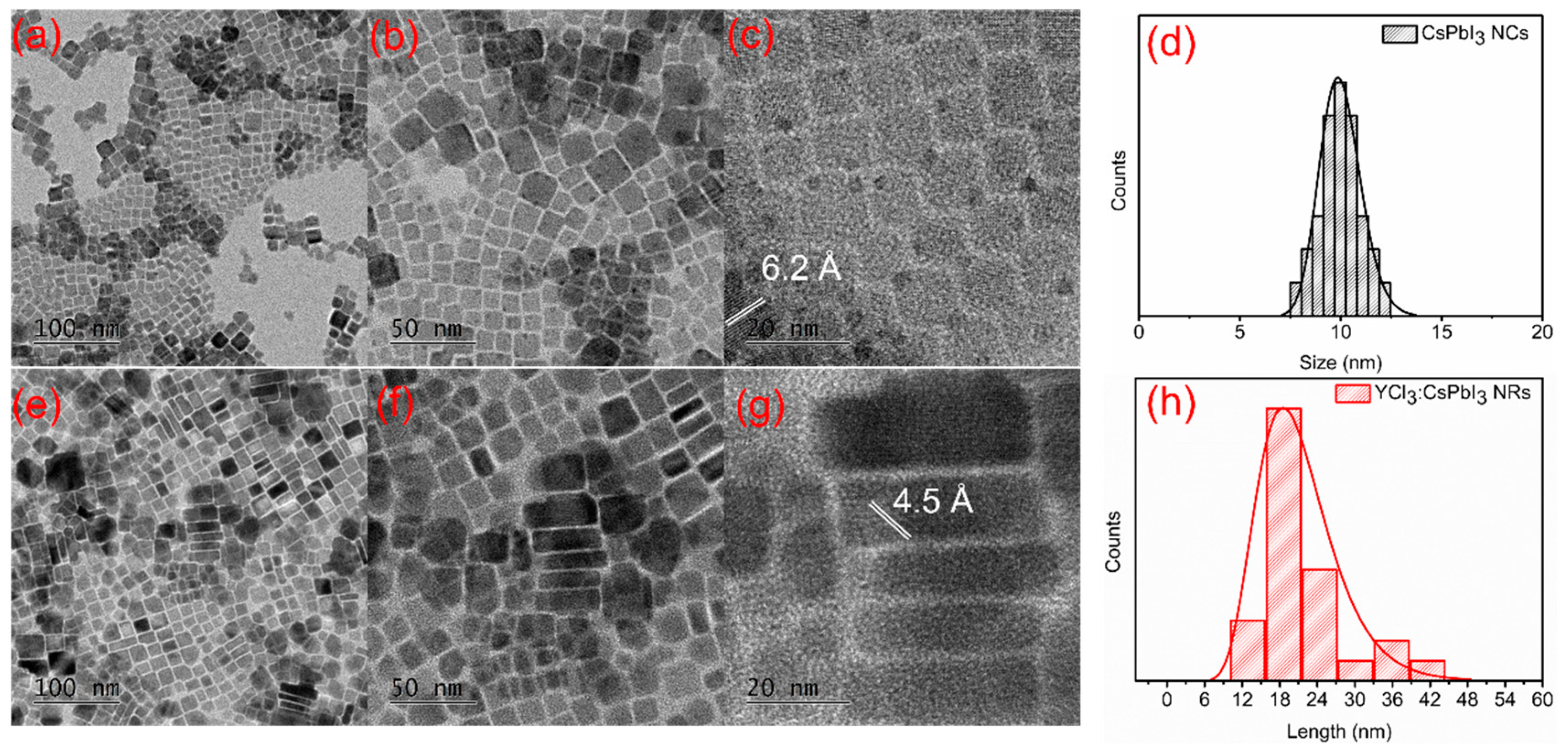

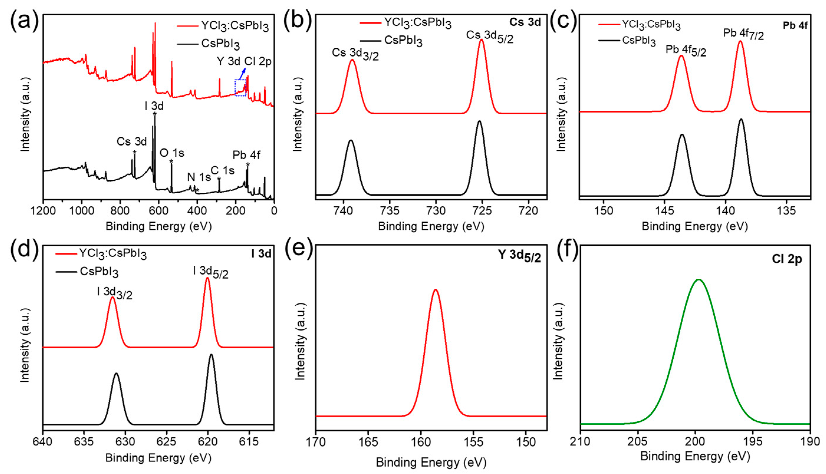
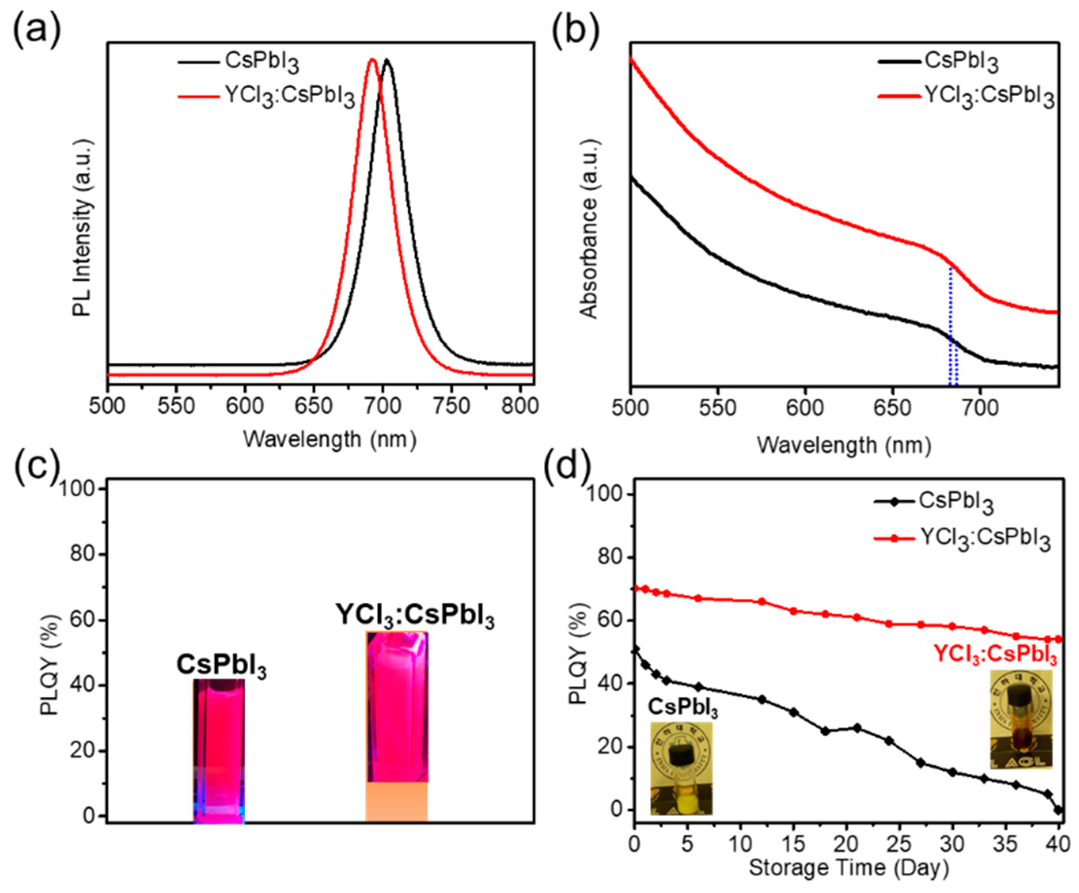
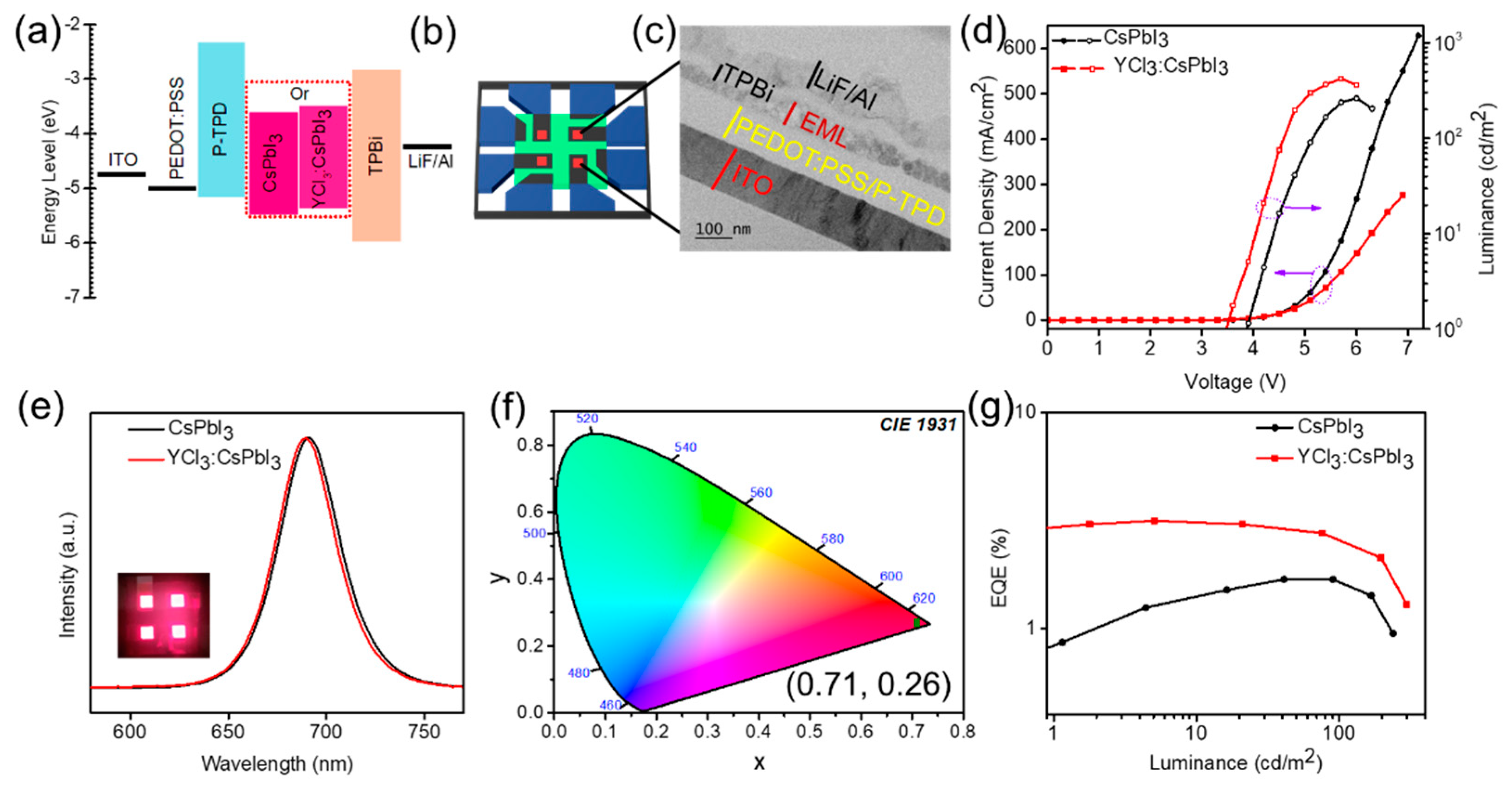
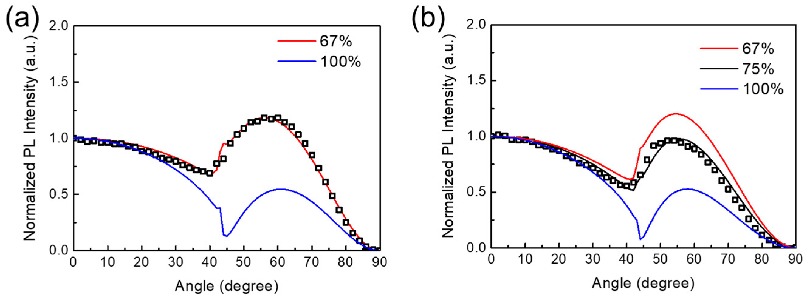
4. Conclusions
Author Contributions
Funding
Data Availability Statement
Acknowledgments
Conflicts of Interest
References
- Kim, Y.-H.; Kim, S.; Kakekhani, A.; Park, J.; Park, J.; Lee, Y.-H.; Xu, H.; Nagane, S.; Wexler, R.B.; Kim, D.-H.; et al. Comprehensive defect suppression in perovskite nanocrystals for high-efficiency light-emitting diodes. Nat. Photonics 2021, 15, 148–155. [Google Scholar] [CrossRef]
- Yang, J.-N.; Chen, T.; Ge, J.; Wang, J.-J.; Yin, Y.-C.; Lan, Y.-F.; Ru, X.-C.; Ma, Z.-Y.; Zhang, Q.; Yao, H.-B. High Color Purity and Efficient Green Light-Emitting Diode Using Perovskite Nanocrystals with the Size Overly Exceeding Bohr Exciton Diameter. J. Am. Chem. Soc. 2021, 143, 19928–19937. [Google Scholar] [CrossRef] [PubMed]
- Saleem, M.I.; Yang, S.; Batool, A.; Sulaman, M.; Veeramalai, C.P.; Jiang, Y.; Tang, Y.; Cui, Y.; Tang, L.; Zou, B. CsPbI3 nanorods as the interfacial layer for high-performance, all-solution-processed self-powered photodetectors. J. Mater. Sci. Technol. 2021, 75, 196–204. [Google Scholar] [CrossRef]
- Saleem, M.I.; Yang, S.; Zhi, R.; Sulaman, M.; Chandrasekar, P.V.; Jiang, Y.; Tang, Y.; Batool, A.; Zou, B. Surface Engineering of All-Inorganic Perovskite Quantum Dots with Quasi Core−Shell Technique for High-Performance Photodetectors. Adv. Mater. Interf. 2020, 7, 2000360. [Google Scholar] [CrossRef]
- Shen, X.; Wang, Z.; Tang, C.; Zhang, X.; Lee, B.R.; Li, X.; Li, D.; Zhang, Y.; Hu, J.; Zhao, D.; et al. Near-Infrared LEDs Based on Quantum Cutting-Activated Electroluminescence of Ytterbium Ions. Nano Lett. 2023, 23, 82–90. [Google Scholar] [CrossRef] [PubMed]
- Wang, Y.-K.; Yuan, F.; Dong, Y.; Li, J.-Y.; Johnston, A.; Chen, B.; Saidaminov, M.I.; Zhou, C.; Zheng, X.; Hou, Y.; et al. All-Inorganic Quantum-Dot LEDs Based on a Phase-Stabilized α-CsPbI3 Perovskite. Angew. Chem. Int. Ed. 2021, 60, 16164–16170. [Google Scholar] [CrossRef] [PubMed]
- Polavarapu, L.; Nickel, B.; Feldmann, J.; Urban, A.S. Advances in Quantum-Confined Perovskite Nanocrystals for Optoelectronics. Adv. Energy Mater. 2017, 7, 1700267. [Google Scholar] [CrossRef]
- Tang, C.; Shen, X.; Yu, S.; Zhong, Y.; Wang, Z.; Hu, J.; Lu, M.; Wu, Z.; Zhang, Y.; Yu, W.W.; et al. Post-treatment of CsPbI3 nanocrystals by p-iodo-D-Phenylalanine for efficient perovskite LEDs. Mater. Today Phys. 2021, 21, 100555. [Google Scholar] [CrossRef]
- Bi, C.; Hu, J.; Yao, Z.; Lu, Y.; Binks, D.; Sui, M.; Tian, J. Self-Assembled Perovskite Nanowire Clusters for High Luminance Red Light-Emitting Diodes. Adv. Funct. Mater. 2020, 30, 2005990. [Google Scholar] [CrossRef]
- Saleem, M.I.; Yang, S.; Zhi, R.; Li, H.; Sulaman, M.; Chandrasekar, P.V.; Zhang, Z.; Batool, A.; Zou, B. Self-powered, all-solution processed, trilayer heterojunction perovskite-based photodetectors. Nanotechnology 2020, 31, 254001. [Google Scholar] [CrossRef]
- Ji, R.; Zhang, Z.; Hofstetter, Y.J.; Buschbeck, R.; Hänisch, C.; Paulus, F.; Vaynzof, Y. Perovskite phase heterojunction solar cells. Nat. Energy 2022. [Google Scholar] [CrossRef]
- Pan, G.; Bai, X.; Shen, X.; Wang, L.; Mao, Y.; Chen, X.; Xu, W.; Shao, H.; Zhou, D.; Dong, B.; et al. Bright red YCl3-promoted CsPbI3 perovskite nanorods towards efficient light-emitting diode. Nano Energy 2021, 81, 105615. [Google Scholar] [CrossRef]
- Tong, Y.; Bladt, E.; Aygüler, M.F.; Manzi, A.; Milowska, K.Z.; Hintermayr, V.A.; Docampo, P.; Bals, S.; Urban, A.S.; Polavarapu, L.; et al. Highly Luminescent Cesium Lead Halide Perovskite Nanocrystals with Tunable Composition and Thickness by Ultrasonication. Angew. Chem. Int. Ed. 2016, 55, 13887–13892. [Google Scholar] [CrossRef] [PubMed]
- Yang, D.; Li, P.; Zou, Y.; Cao, M.; Hu, H.; Zhong, Q.; Hu, J.; Sun, B.; Duhm, S.; Xu, Y.; et al. Interfacial Synthesis of Monodisperse CsPbBr3 Nanorods with Tunable Aspect Ratio and Clean Surface for Efficient Light-Emitting Diode Applications. Chem. Mater. 2019, 31, 1575–1583. [Google Scholar] [CrossRef]
- Cui, J.; Liu, Y.; Deng, Y.; Lin, C.; Fang, Z.; Xiang, C.; Bai, P.; Du, K.; Zuo, X.; Wen, K.; et al. Efficient light-emitting diodes based on oriented perovskite nanoplatelets. Sci. Adv. 2021, 7, eabg8458. [Google Scholar] [CrossRef] [PubMed]
- Jurow, M.J.; Morgenstern, T.; Eisler, C.; Kang, J.; Penzo, E.; Do, M.; Engelmayer, M.; Osowiecki, W.T.; Bekenstein, Y.; Tassone, C.; et al. Manipulating the Transition Dipole Moment of CsPbBr3 Perovskite Nanocrystals for Superior Optical Properties. Nano Lett. 2019, 19, 2489–2496. [Google Scholar] [CrossRef] [PubMed]
- Walters, G.; Haeberlé, L.; Quintero-Bermudez, R.; Brodeur, J.; Kéna-Cohen, S.; Sargent, E.H. Directional Light Emission from Layered Metal Halide Perovskite Crystals. J. Phys. Chem. Lett. 2020, 11, 3458–3465. [Google Scholar] [CrossRef] [PubMed]
- Hoang, M.T.; Pannu, A.S.; Yang, Y.; Madani, S.; Shaw, P.; Sonar, P.; Tesfamichael, T.; Wang, H. Surface Treatment of Inorganic CsPbI3 Nanocrystals with Guanidinium Iodide for Efficient Perovskite Light-Emitting Diodes with High Brightness. Nano-Micro Lett. 2022, 14, 69. [Google Scholar] [CrossRef]
- Kim, Y.-H.; Zhai, Y.; Lu, H.; Pan, X.; Xiao, C.; Gaulding, E.A.; Harvey, S.P.; Berry, J.J.; Vardeny, Z.V.; Luther, J.M.; et al. Chiral-induced spin selectivity enables a room-temperature spin light-emitting diode. Science 2021, 371, 1129–1133. [Google Scholar] [CrossRef] [PubMed]
- Li, H.; Lin, H.; Ouyang, D.; Yao, C.; Li, C.; Sun, J.; Song, Y.; Wang, Y.; Yan, Y.; Wang, Y.; et al. Efficient and Stable Red Perovskite Light-Emitting Diodes with Operational Stability >300 h. Adv. Mater. 2021, 33, 2008820. [Google Scholar] [CrossRef]
- Tang, Y.; Cao, X.; Honarfar, A.; Abdellah, M.; Chen, C.; Avila, J.; Asensio, M.-C.; Hammarström, L.; Sa, J.; Canton, S.E.; et al. Inorganic Ions Assisted the Anisotropic Growth of CsPbCl3 Nanowires with Surface Passivation Effect. ACS Appl. Mater. Interf. 2018, 10, 29574–29582. [Google Scholar] [CrossRef]
- Protesescu, L.; Yakunin, S.; Bodnarchuk, M.I.; Krieg, F.; Caputo, R.; Hendon, C.H.; Yang, R.X.; Walsh, A.; Kovalenko, M.V. Nanocrystals of Cesium Lead Halide Perovskites (CsPbX3, X = Cl, Br, and I): Novel Optoelectronic Materials Showing Bright Emission with Wide Color Gamut. Nano Lett. 2015, 15, 3692–3696. [Google Scholar] [CrossRef] [PubMed]
- Lu, M.; Guo, J.; Sun, S.; Lu, P.; Wu, J.; Wang, Y.; Kershaw, S.V.; Yu, W.W.; Rogach, A.L.; Zhang, Y. Bright CsPbI3 Perovskite Quantum Dot Light-Emitting Diodes with Top-Emitting Structure and a Low Efficiency Roll-Off Realized by Applying Zirconium Acetylacetonate Surface Modification. Nano Lett. 2020, 20, 2829–2836. [Google Scholar] [CrossRef] [PubMed]
- Zhu, Y.; Zhao, J.; Yang, G.; Xu, X.; Pan, G. Ammonium acetate passivated CsPbI3 perovskite nanocrystals for efficient red light-emitting diodes. Nanoscale 2020, 12, 7712–7719. [Google Scholar] [CrossRef] [PubMed]
- Pan, G.; Bai, X.; Yang, D.; Chen, X.; Jing, P.; Qu, S.; Zhang, L.; Zhou, D.; Zhu, J.; Xu, W.; et al. Doping Lanthanide into Perovskite Nanocrystals: Highly Improved and Expanded Optical Properties. Nano Lett. 2017, 17, 8005–8011. [Google Scholar] [CrossRef] [PubMed]
- Yao, J.-S.; Ge, J.; Wang, K.-H.; Zhang, G.; Zhu, B.-S.; Chen, C.; Zhang, Q.; Luo, Y.; Yu, S.-H.; Yao, H.-B. Few-Nanometer-Sized α-CsPbI3 Quantum Dots Enabled by Strontium Substitution and Iodide Passivation for Efficient Red-Light Emitting Diodes. J. Am. Chem. Soc. 2019, 141, 2069–2079. [Google Scholar] [CrossRef] [PubMed]
- Xia, W.; Ren, Z.; Zheng, Z.; Luo, C.; Li, J.; Ma, W.; Zhou, X.; Chen, Y. Highly stable lanthanide-doped CsPbI3 perovskite nanocrystals with near-unity quantum yield for efficient red light-emitting diodes. Nanoscale 2023, 15, 1109–1118. [Google Scholar] [CrossRef] [PubMed]
- Shen, X.; Zhang, Y.; Kershaw, S.V.; Li, T.; Wang, C.; Zhang, X.; Wang, W.; Li, D.; Wang, Y.; Lu, M.; et al. Zn-Alloyed CsPbI3 Nanocrystals for Highly Efficient Perovskite Light-Emitting Devices. Nano Lett. 2019, 19, 1552–1559. [Google Scholar] [CrossRef] [PubMed]
- Chen, D.; Ko, P.K.; Li, C.H.A.; Zou, B.; Geng, P.; Guo, L.; Halpert, J.E. Amino Acid-Passivated Pure Red CsPbI3 Quantum Dot LEDs. ACS Energy Lett. 2023, 8, 410–416. [Google Scholar] [CrossRef]
- Jurow, M.J.; Lampe, T.; Penzo, E.; Kang, J.; Koc, M.A.; Zechel, T.; Nett, Z.; Brady, M.; Wang, L.-W.; Alivisatos, A.P.; et al. Tunable Anisotropic Photon Emission from Self-Organized CsPbBr3 Perovskite Nanocrystals. Nano Lett. 2017, 17, 4534–4540. [Google Scholar] [CrossRef]
- Barnes, W.L. Fluorescence near interfaces: The role of photonic mode density. J. Modern Optics 1998, 45, 661–699. [Google Scholar] [CrossRef]
- Jeon, S.; Zhao, L.; Jung, Y.-J.; Kim, J.W.; Kim, S.-Y.; Kang, H.; Jeong, J.-H.; Rand, B.P.; Lee, J.-H. Perovskite Light-Emitting Diodes with Improved Outcoupling Using a High-Index Contrast Nanoarray, Small 2019, 15, 1900135. Small 2019, 15, 1900135. [Google Scholar] [CrossRef] [PubMed]
- He, S.; Kumar, N.; Lee, H.B.; Ko, K.-J.; Jung, Y.-J.; Kim, J.I.; Bae, S.; Lee, J.-H.; Kang, J.-W. Tailoring the refractive index and surface defects of CsPbBr3 quantum dots via alkyl cation-engineering for efficient perovskite light-emitting diodes. Chem. Eng. J. 2021, 425, 130678. [Google Scholar] [CrossRef]
- Cheon, H.J.; Woo, S.-J.; Baek, S.-H.; Lee, J.-H.; Kim, Y.-H. Dense Local Triplet States and Steric Shielding of Multi-Resonance TADF Emitter Enable High-Performance Deep Blue OLEDs. Adv. Mater. 2022, 34, 2207416. [Google Scholar] [CrossRef] [PubMed]
Disclaimer/Publisher’s Note: The statements, opinions and data contained in all publications are solely those of the individual author(s) and contributor(s) and not of MDPI and/or the editor(s). MDPI and/or the editor(s) disclaim responsibility for any injury to people or property resulting from any ideas, methods, instructions or products referred to in the content. |
© 2023 by the authors. Licensee MDPI, Basel, Switzerland. This article is an open access article distributed under the terms and conditions of the Creative Commons Attribution (CC BY) license (http://creativecommons.org/licenses/by/4.0/).


