Submitted:
22 March 2023
Posted:
27 March 2023
You are already at the latest version
Abstract
Keywords:
1. Introduction
- Consequently, the innovation of the current research is related to:
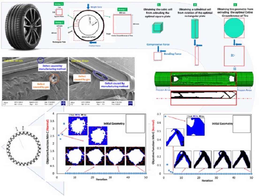
- the optimization of the metamaterial cell with three materials and its possible application in non-pneumatic tires,
- and the production and the examination of how to connect materials and the quality of 3D printing.
2. Materials and Methods
2.1. Samples
2.2. Materials Specifications
2.3. Optimization Procedures
2.4. Printing Quality
3. Results and Discussion
3.1. Outputs for Square Plane
3.2. Outputs for Rectangular Plane
3.3. Entire Circumference of Tire
3.5. Outputs for The Quality of 3D Printing
4. Conclusions
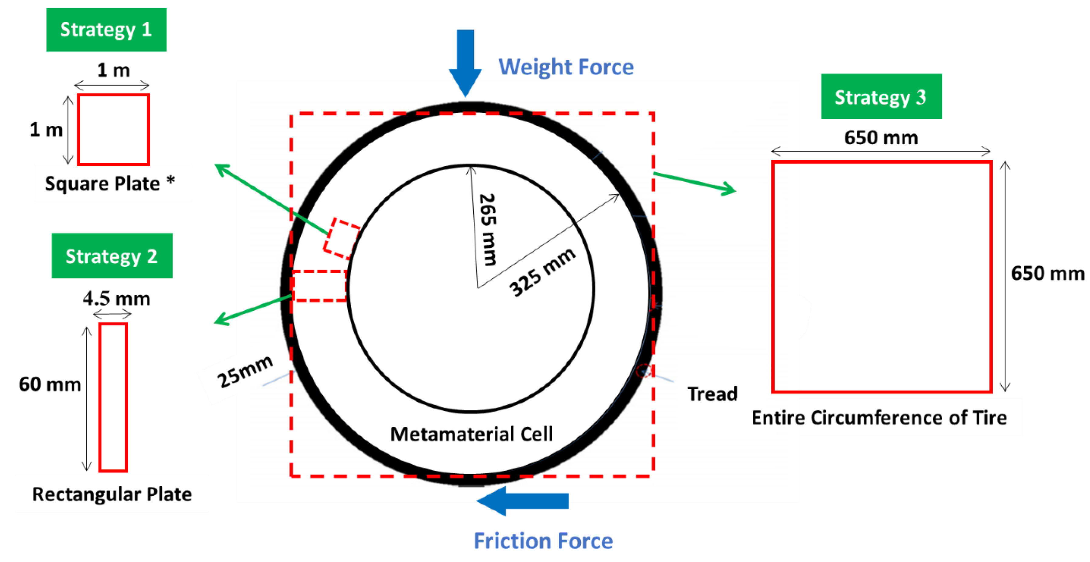
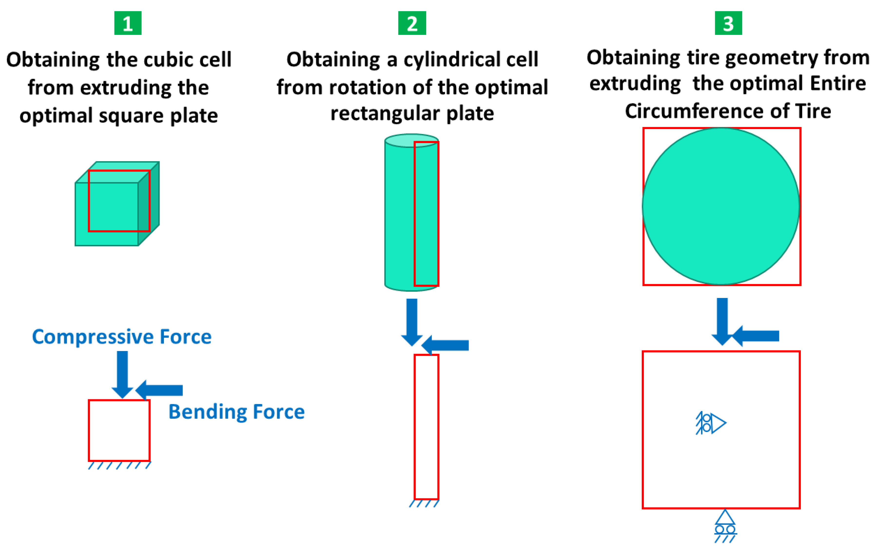
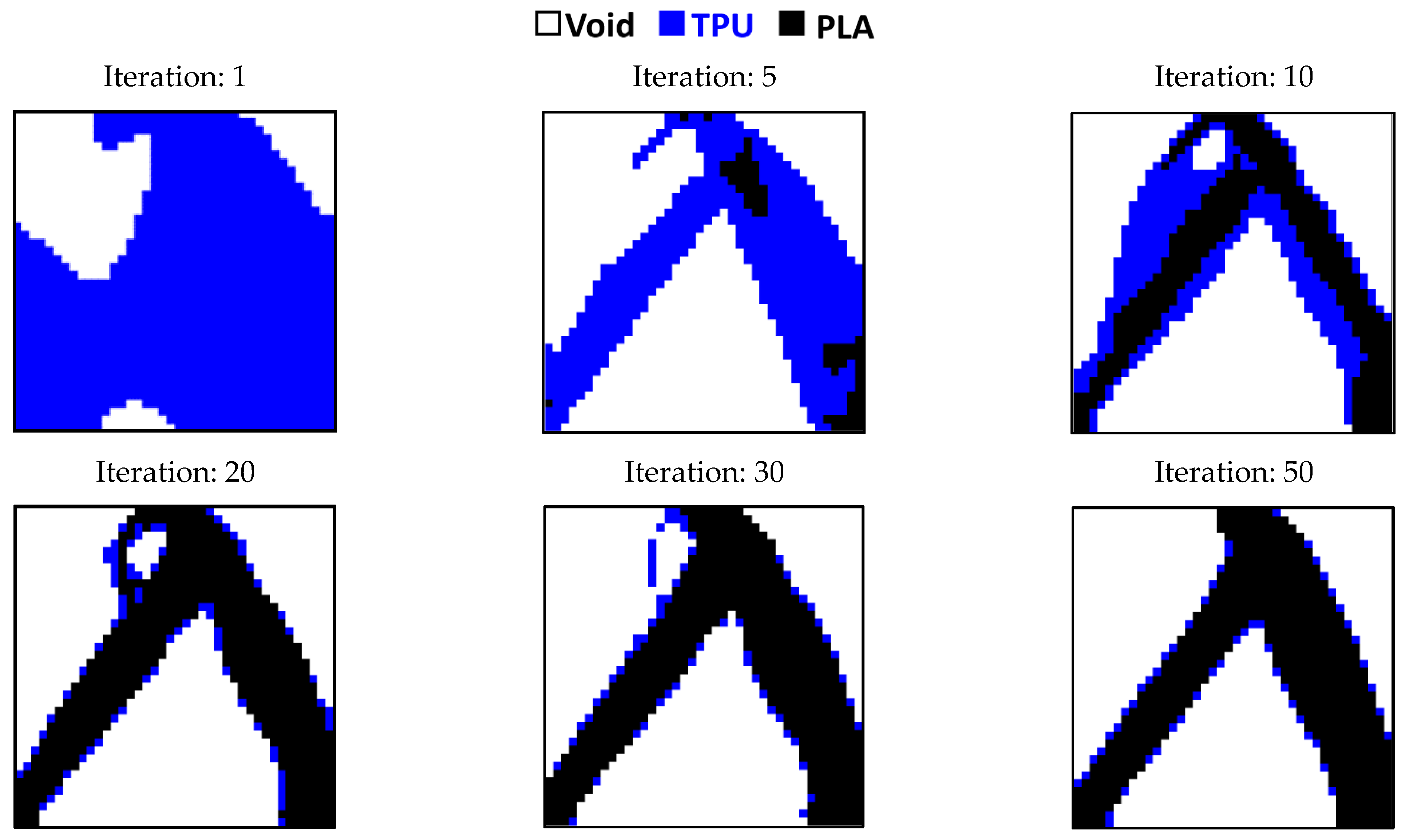
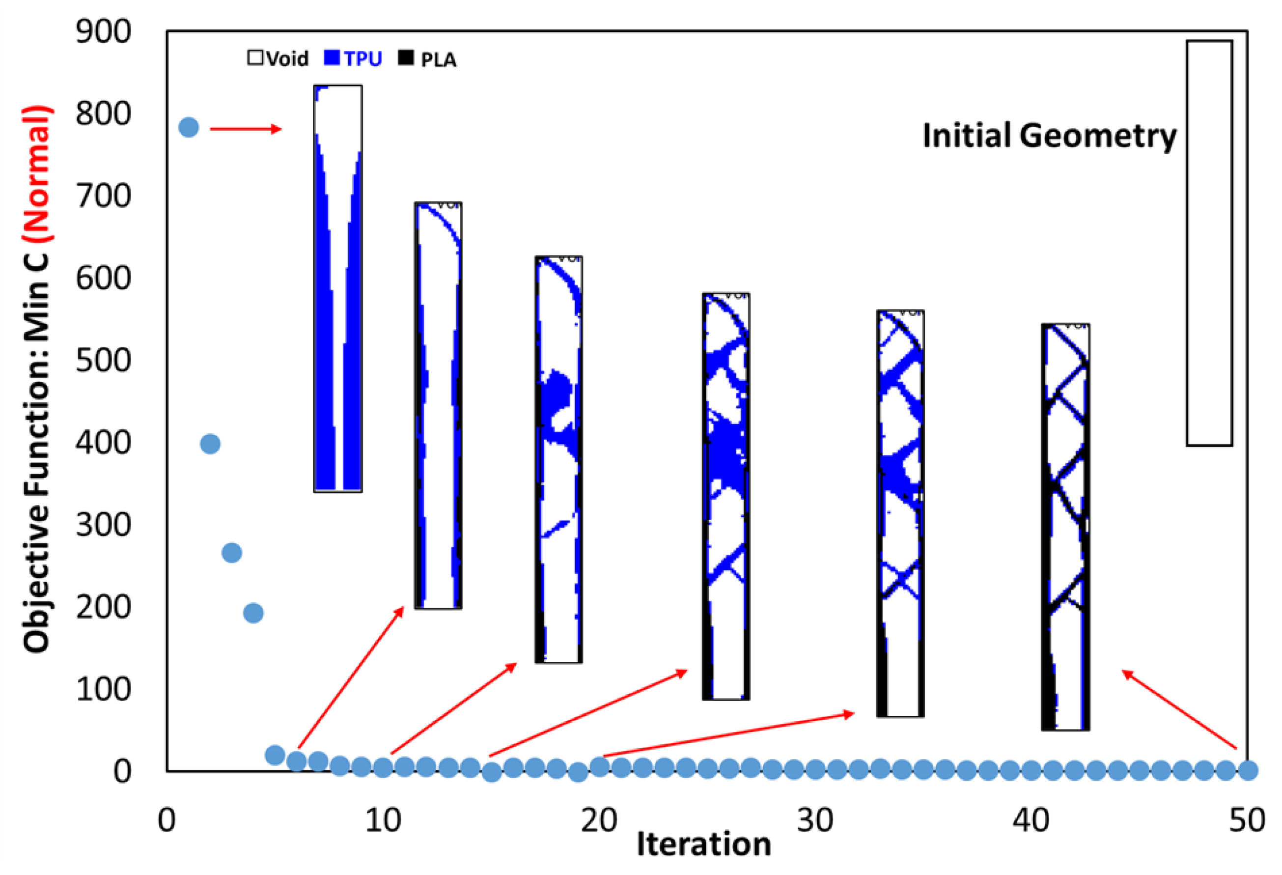
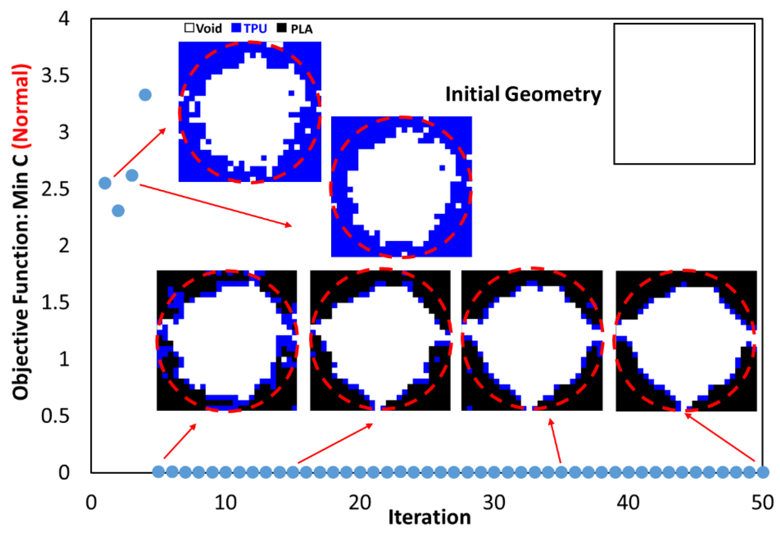
- In the optimization of the square plane, the sample with the remaining weight constraint equal to 40% is selected as the optimal sample.
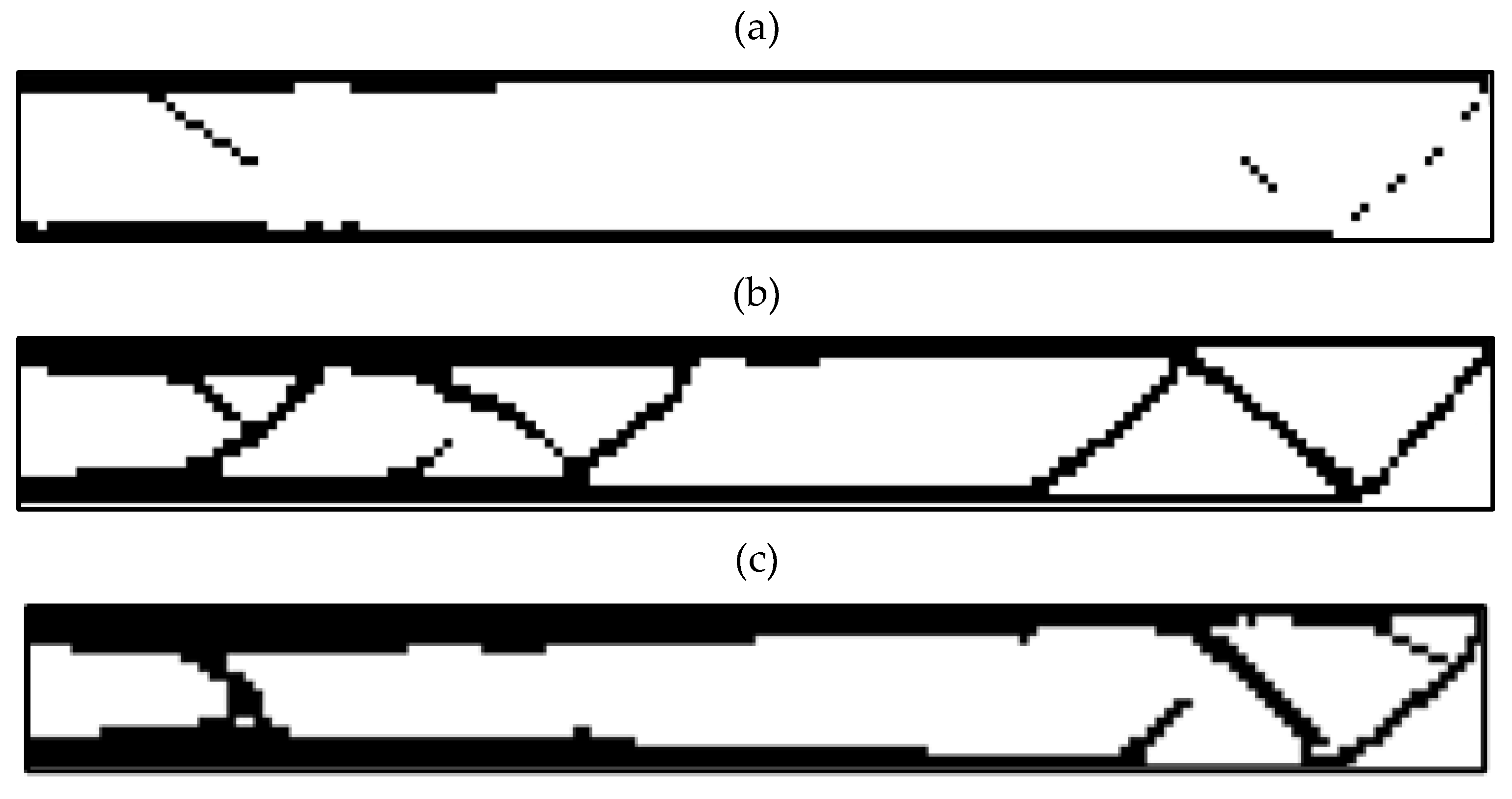
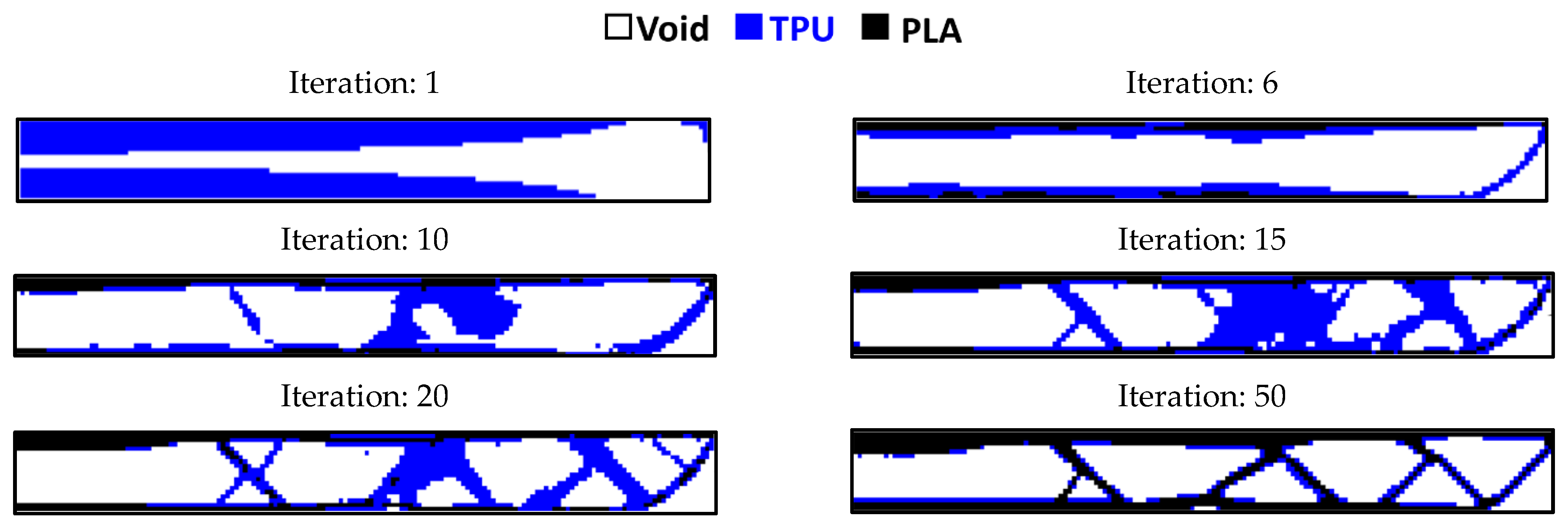
- in the optimization of the rectangular plane, the sample with the remaining weight constraint equal to 60% is selected as the optimal sample.
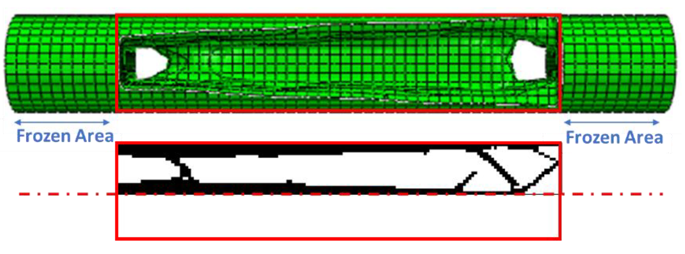
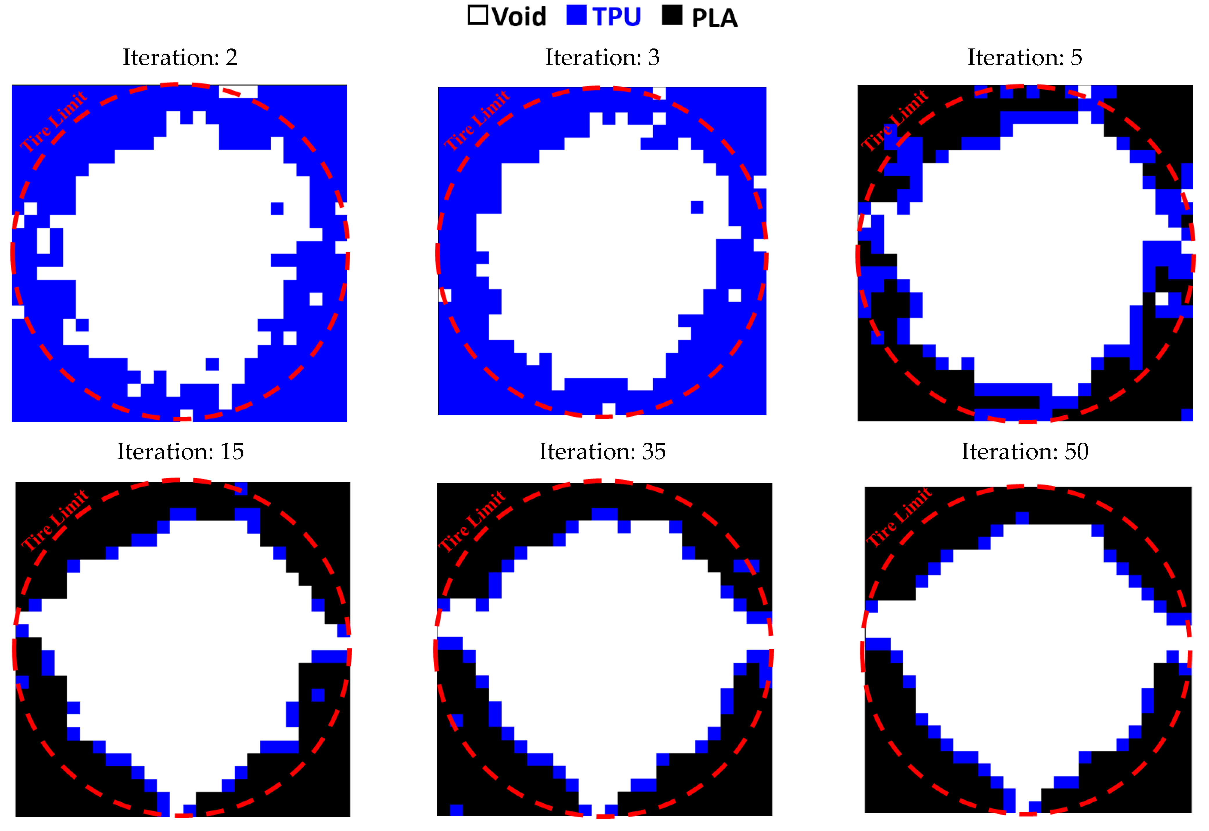
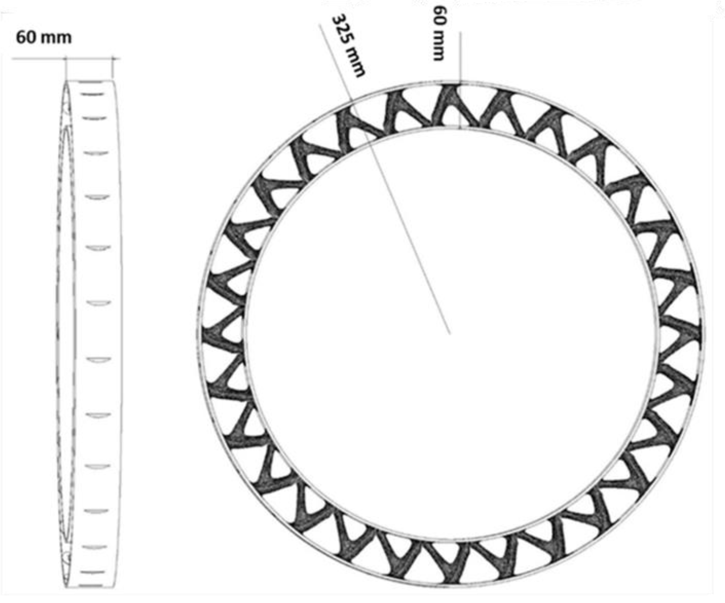
- In the optimization of the entire circumference of tire, the sample with a remaining weight of less than 60% has been selected as the optimal sample.
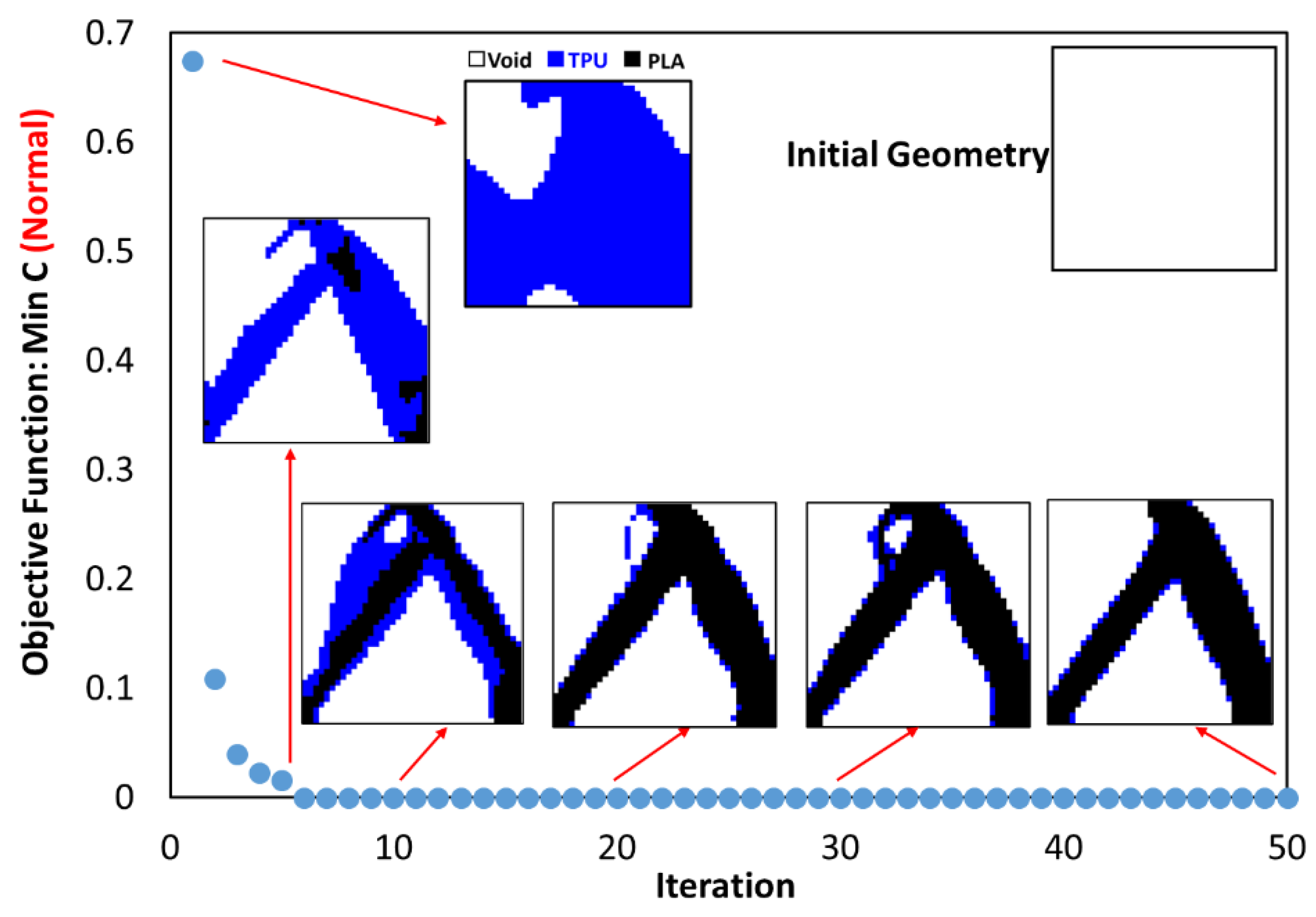
- The objective function for all three problems in the optimal distribution of materials is convergent and acceptable.
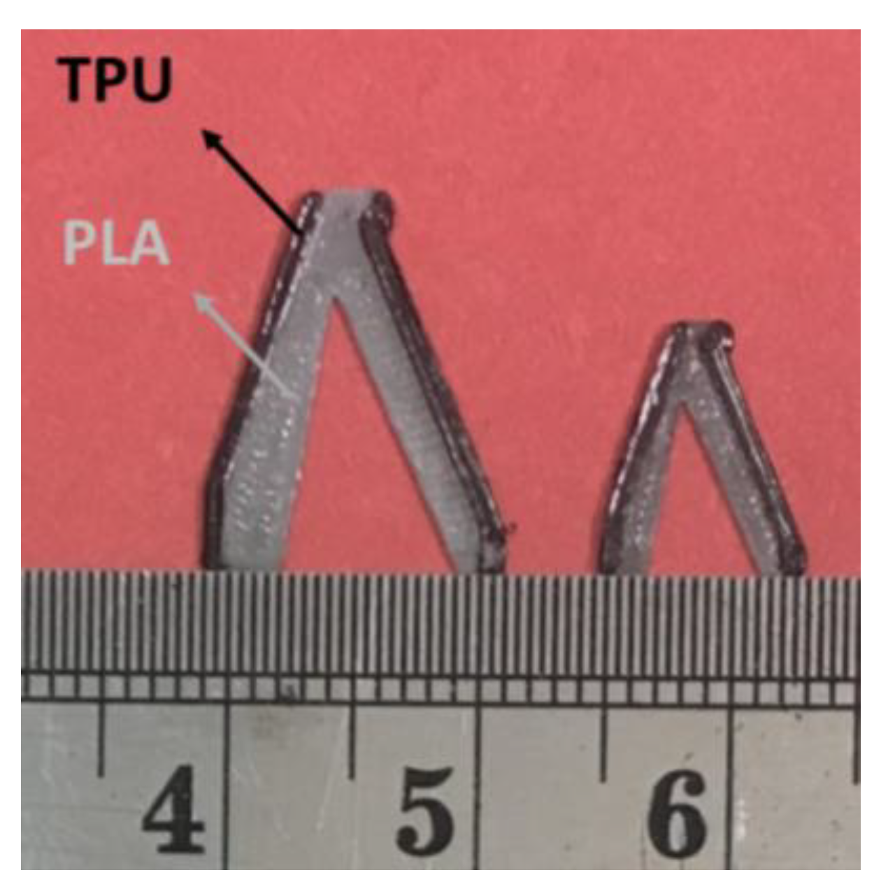
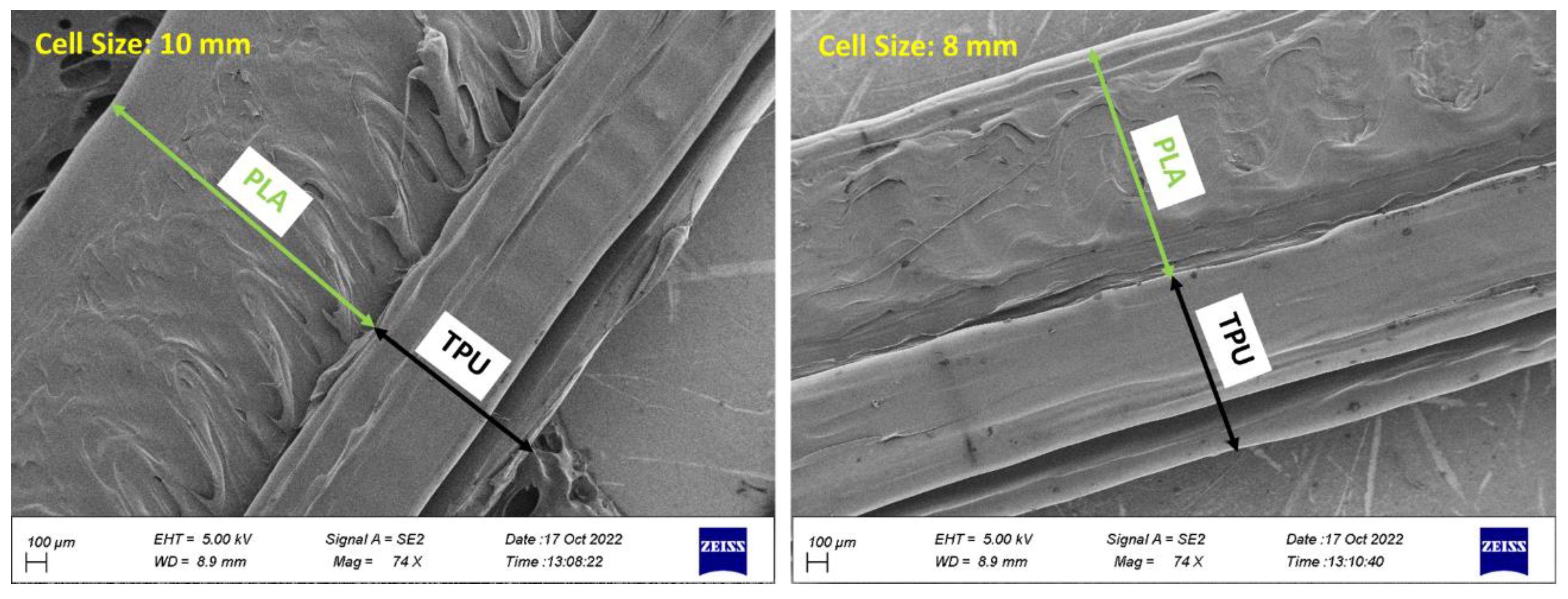
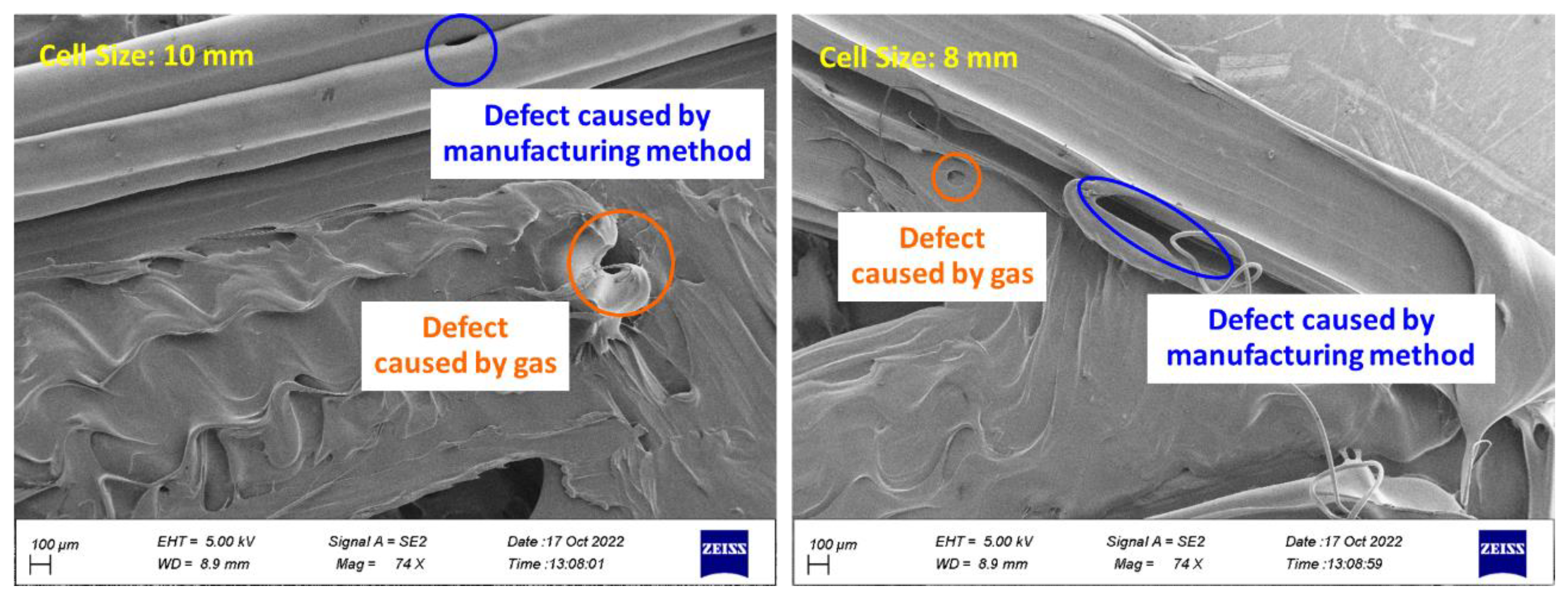
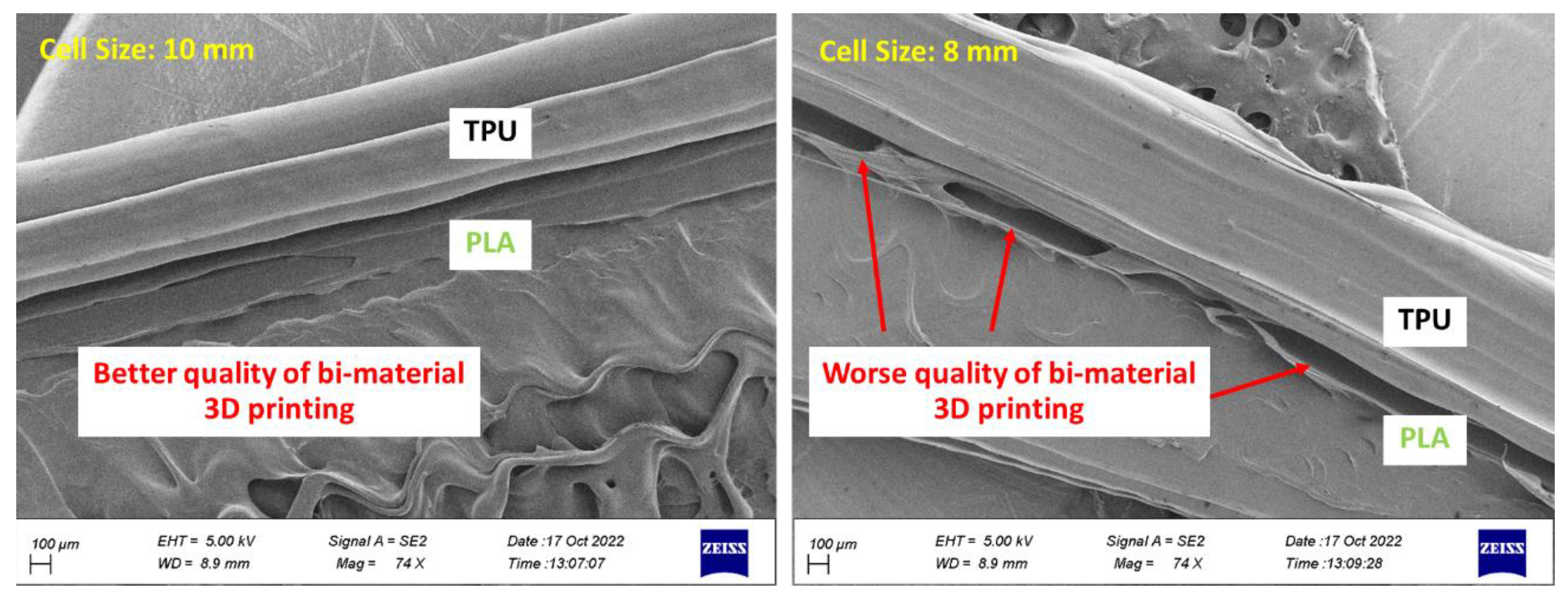
- PLA and TPU materials are completely connected based on FE-SEM images.
Author Contributions
Funding
Institutional Review Board Statement
Data Availability Statement
Conflicts of Interest
Appendix A

References
- Li, T.; Hu, X.; Chen, Y.; Wang, L. Harnessing out-of-plane deformation to design 3D architected lattice metamaterials with tunable Poisson’s ratio. Scientific Reports 2017, 7, 1–10. [Google Scholar] [CrossRef]
- Askari, M.; Hutchins, D.A.; Thomas, P.J.; Astolfi, L.; Watson, R.L.; Abdi, M.; Ricci, M.; Laureti, S.; Nie, L.; Freear, S.; Wildman, R.; Tuck, C.; Clarke, M.; Woods, E.; Clare, A.T. Additive manufacturing of metamaterials: A review. Additive Manufacturing 2020, 101562. [Google Scholar] [CrossRef]
- Refai, K.; Brugger, C.; Montemurro, M.; Saintier, N. An experimental and numerical study of the high cycle multiaxial fatigue strength of titanium lattice structures produced by Selective Laser Melting. International Journal of Fatigue 2020, 138, 105623. [Google Scholar] [CrossRef]
- Benedetti, M.; du Plessis, A.; Ritchie, R.O.; Dallago, M.; Razavi, S.M.J.; Berto, F. Architected cellular materials: A review on their mechanical properties towards fatigue-tolerant design and fabrication. Materials Science and Engineering R: Reports, 1006. [Google Scholar]
- Jia, Z.; Liu, F.; Jiang, X.; Wang, L. Engineering lattice metamaterials for extreme property, programmability, and multifunctionality. Journal of Applied Physics 2020, 127, 150901. [Google Scholar] [CrossRef]
- Deptuła, A.; Osiński, P. The Optimization of Three-Involute Tooth Outline with Taking into Consideration Multi-valued Logic Trees. Proceedings of the 13th International Scientific Conference, 2017. [Google Scholar]
- Jafferson, J.M.; Sharma, H. Design of 3D printable airless tyres using NTopology. Materials Today: Proceedings, 1147. [Google Scholar]
- Sandberg, U. The Airless Tire: Will this Revolutionary Concept be the Tire of the Future? Modern Concepts in Material Science 2020, 3. [Google Scholar] [CrossRef]
- Jin, X.; Hou, C.; Fan, X.; Sun, Y.; Lv, J.; Lu, C. Investigation on the static and dynamic behaviors of non-pneumatic tires with honeycomb spokes. Composite Structures 2018, 187, 27–35. [Google Scholar] [CrossRef]
- Mazur, V.V. Experiments to Find the Rolling Resistance of Non-pneumatic Tires Car Wheels. Proceedings of the 5th International Conference on Industrial Engineering 2020, 641–648. [Google Scholar]
- Deziania, S.; Azadi, M. A review on metamaterial types, additive manufacturing technique and its application in automotive industry. Scientific journal of the Iranian Society of Mechanical Engineers 2021, 4, 70–80. [Google Scholar]
- Suvanjumrat, C.; Rugsaj, R. Study of 3D printing for forming spoke of non-pneumatic tire using finite element method. IOP Conference Series: Materials Science and Engineering, 2021; 1137, 012020. [Google Scholar]
- Rugsaj, R.; Suvanjumrat, C. Dynamic Finite Element Analysis of Rolling Non-Pneumatic Tire. International Journal of Automotive Technology 2021, 22, 1022. [Google Scholar] [CrossRef]
- Rugsaj, R.; Suvanjumrat, C. Determination of material property for non-pneumatic tire spokes by inverse method. Key Engineering Materials 2018, 777, 411–415. [Google Scholar] [CrossRef]
- Rugsaj, R.; Suvanjumrat, C. Proper Radial Spokes of Non-Pneumatic Tire for Vertical Load Supporting by Finite Element Analysis. International Journal of Automotive Technology 2019, 20, 801–812. [Google Scholar] [CrossRef]
- Ramachandran, M.; Nonlinear Finite Element Analysis of Tweel Geometric Parameter Modifications on Spoke Dynamics During High-Speed Rolling. Master of Science, Clemson University, USA, 2008.
- Manibaalan, C.; Keshore, B.S.; Haran, J.C. Static Analysis of Airless Tyres. International Journal of Scientific and Research Publications 2013, 3, 1–4. [Google Scholar]
- Zmuda, M.; Jackowski, J.; Hryciów, Z. Numerical research of selected features of the non-pneumatic tire. AIP Conference Proceedings 2019, 2078. [Google Scholar]
- Ma, J.; Summers, J.; Joseph, P. Dynamic impact simulation of interaction between non-pneumatic tire and sand with obstacle. SAE 2011 World Congress and Exhibition 2011, 12. [Google Scholar]
- Ma, J.; Summers, J.D.; Joseph, P.F. Numerical simulation of tread effects on the interaction between cellular shear band based non-pneumatic tire and sand. Proceedings of the ASME Design Engineering Technical Conference 2011, 8, 769–779. [Google Scholar]
- Shankar, P.; Fazelpour, M.; Summers, J.D. An energy-based design approach for a meso-structure with high shear flexure. Proceedings of the ASME Design Engineering Technical Conference 2013, 3. [Google Scholar]
- Ma, J.; Louis, S.; Summers, J.D.; Joseph, P.F. Numerical Investigation of Effect of Membrane on Thickness on the Performance of Cellular Shear Band Based non- pneumatic Tire. Engineering Conference, 2011; 1–11. [Google Scholar]
- Tavakoli, R. Multimaterial topology optimization by volume constrained Allen–Cahn system and regularized projected steepest descent method. Computer Methods in Applied Mechanics and Engineering 2014, 276, 534–565. [Google Scholar] [CrossRef]
- Han, Z.; Gu, Z.; Ma, X.; Chen, W. Multi material layout optimization of truss structures via an improved particle swarm optimization algorithm. Computers and Structures 2019, 222, 10–24. [Google Scholar]
- Chen, Y.; Ye, L.; Xu, C.; Zhang, Y.X. Multi-material topology optimization of micro-composites with reduced stress concentration for optimal functional performance. Materials & Design, 2021; 210, 110098. [Google Scholar]
- Chung, H.; Du, Z. Optimized Design of Multi- Material Cellular Structures by a Level-Set Method with Guyan Reduction. Journal of Mechanical Design 2021, 143, 101702. [Google Scholar] [CrossRef]
- Mansouri, M.R.; Montazerian, H.; Schmauder, S. 3D-printed multimaterial composites tailored for compliancy and strain recovery., Composite Structures 2018. 184, 11–17.
- Gao, X.; Caivano, R.; Tridello, A.; Chiandussi, G.; Ma, H.; Paolino, D.; Berto, F. Innovative formulation for topological fatigue optimisation based on material defects distribution and TopFat algorithm. International Journal of Fatigue 2021, 17, 106176. [Google Scholar] [CrossRef]
- Gao, J.; Wang, L.; Xiao, M.; Gao, L.; Li, P. An iso geometric approach to topological optimization design of auxetic composites with tri-material micro-architectures. Composite Structures 2021, 271, 114163. [Google Scholar] [CrossRef]
- Huang, X.; Li, W. A new multi-material topology optimization algorithm and selection of candidate materials. Computer Methods in Applied Mechanics and Engineering 2021, 386, 114114. [Google Scholar] [CrossRef]
- Li,H., Luo, Z., Gao, L., Walker, P., Topology optimization for functionally graded cellular composites with metamaterials by level sets. Computer Methods in Applied Mechanics and Engineering 2018, 328, 340–364. [CrossRef]
- Nguyen, C. , Zhuang, X., Chamoin, L., Zhao, X., Nguyen-Xuan, H., Rabczuk, T., Three-dimensional topology optimization of auxetic metamaterial using isogeometric analysis and model order reduction. Computer Methods in Applied Mechanics and Engineering 2020, 371, 113306. [Google Scholar] [CrossRef]
- Vogiatzis, P.; Chen, S.; Wang, X.; Li, T.; Wang, L. Topology Optimization of Multi-Material Negative Poisson’s Ratio Metamaterials Using a Reconciled Level Set Method. Computer-Aided Design, 2017; 83, 15–32. [Google Scholar]
- Huikai, Z.; Yangjun, L.; Kang, Z. Bi-material microstructural design of chiral auxetic metamaterials using topology optimization. Composite Structures 2018, 195, 232–248. [Google Scholar]
- Zheng, Y.; Wang, Y.; Lu, X.; Zheng, J.; Qu, J. Topology optimization for isotropic mechanical metamaterials considering material uncertainties. Mechanics of Materials 2021, 155, 103742. [Google Scholar] [CrossRef]
- Wei, W.; Kai, Z.; Shaoyi, B.; Lanchun, Z.; Yongzhi, W. Vibration performance analysis of vehicle with the non-pneumatic new mechanical elastic wheel in the impulse input experiment. Journal of Vibroengineering 2016, 18, 3970–3980. [Google Scholar] [CrossRef]
- Zhao, Y.; Du, X.; Lin, F.; Wang, Q.; Fu, H. Static stiffness characteristics of a new non-pneumatic tire with different hinge structure and distribution. Journal of Mechanical Science and Technology 2018, 32, 3057–3064. [Google Scholar] [CrossRef]
- Zhao, Y.Q.; Deng, Y.J.; Lin, F.; Zhu, M.M.; Xiao, Z. Transient Dynamic Characteristics of a Non-Pneumatic Mechanical Elastic Wheel Rolling Over a Ditch. International Journal of Automotive Technology 2018, 19, 499–508. [Google Scholar] [CrossRef]
- Deng, Y.; Zhao, Y.; Lin, F.; Xiao, Z.; Zhu, M.; Li, H. , Simulation of steady-state rolling non-pneumatic mechanical elastic wheel using finite element method. Simulation Modelling Practice and Theory 2018, 85, 60–79. [Google Scholar] [CrossRef]
- Du, X.; Zhao, Y.; Wang, Q.; Fu, H.; Lin, F. Grounding characteristics of a non-pneumatic mechanical elastic tire in a rolling state with a camber angle. Strojniski Vestnik/Journal of Mechanical Engineering, 2019; 65, 287–296. [Google Scholar]
- Du, X.; Zhao, Y.; Lin, F.; Fu, H.; Wang, Q. , Numerical and experimental investigation on the camber performance of a non-pneumatic mechanical elastic wheel. Journal of the Brazilian Society of Mechanical Sciences and Engineering 2017, 39, 3315–3327. [Google Scholar] [CrossRef]
- Xiao, Z.; Zhao, Y.Q.; Lin, F.; Zhu, M.M.; Deng, Y.J. Studying the fatigue life of a non-pneumatic wheel by using finite-life design for life prediction. Journal of Mechanical Engineering 2018, 64, 56–67. [Google Scholar]
- Zhao, Y.Q.; Xiao, Z.; Lin, F.; Zhu, M.M.; Deng, Y.J. Influence analysis of machining and installation errors on the radial stiffness of a non-pneumatic mechanical elastic wheel. Chinese Journal of Mechanical Engineering 2018, 31, 1–9. [Google Scholar] [CrossRef]
- Mathew, N.J.; Sahoo, D.K.; Chakravarthy, E.M. Design and Static Analysis of Airlesstyre to Reduce Deformation. IOP Conference Series: Materials Science and Engineering, 2017; 197, 012042. [Google Scholar]
- Zhang, Z.; Fu, H.; Zhao, Q.; Tan, D.; Yang, K. Pattern design and performance analysis of a flexible spoke bionic non-pneumatic tire. Journal of the Brazilian Society of Mechanical Sciences and Engineering 2021, 43, 1–11. [Google Scholar] [CrossRef]
- Zhang, Z.; Fu, H.; Liang, X.; Chen, X.; Tan, D. Comparative Analysis of Static and Dynamic Performance of Nonpneumatic Tire with Flexible Spoke Structure. Strojniski Vestnik/Journal of Mechanical Engineering, 2020; 66, 458–466. [Google Scholar]
- Wang, J.; Yang, B.; Lin, X.; Gao, L.; Liu, T.; Lu, Y.; Wang, R. Research of TPU Materials for 3D Printing Aiming at Non-Pneumatic Tires by FDM Method. Polymers 2020, 12, 2492. [Google Scholar] [CrossRef] [PubMed]
- Ganniari-Papageorgiou, E.; Chatzistergos, P.; Wang, X. The Influence of the Honeycomb Design Parameters on the Mechanical Behavior of Non-Pneumatic Tires. International Journal of Applied Mechanics 2020, 12, 2050024. [Google Scholar] [CrossRef]
- Zheng, Z.; Rakheja, S.; Sedaghati, R. Multi-axis stiffness and road contact characteristics of honeycomb wheels: A parametric analysis using Taguchi method. Composite Structures 2022, 279, 114735. [Google Scholar] [CrossRef]
- Fu, H.; Chen, X.; Zhao, Q.; Xiao, Z.; Liang, X. Fatigue life prediction and influencing factors analysis of mesh flexible spoke non-pneumatic tire. Advances in Mechanical Engineering 2021, 13, 1–10. [Google Scholar]
- Gasmi, A.; Joseph, P.F.; Rhyne, T.B.; Cron, S.M. Development of a two-dimensional model of a compliant non-pneumatic tire. International Journal of Solids and Structures 2012, 49, 1723–1740. [Google Scholar] [CrossRef]
- Ju, J.; Kim, D.M.; Kim, K. Flexible cellular solid spokes of a non-pneumatic tire. Composite Structures 2012, 94, 2285–2295. [Google Scholar] [CrossRef]
- Maharaj, Y.; James, K.A. Metamaterial topology optimization of nonpneumatic tires with stress and buckling constraints. International Journal for Numerical Methods in Engineering 2020, 121, 1410–1439. [Google Scholar] [CrossRef]
- Petrone, F.; Fichera, G.; Lacagnina, M. A numerical model to analyze the dynamic response of a vehicle to variations in torque transmitted by the drive-line. SAE International Journal of Passenger Cars - Mechanical Systems, 2001; 2, 1–12. [Google Scholar]
- Hsiao, T.; Liu, N.; Chen, S. Robust Estimation of the Friction Forces Generated by Each Tire of a Vehicle. 2011 American Control Conference 2011, 5261–5266. [Google Scholar]
- Torres, J.; Cotelo, J.; Karl, J.; Gordon, A.P. Mechanical property optimization of FDM PLA in shear with multiple objectives. The Minerals, Metals & Materials Society Mechanical, 2015; 67, 1183–1193. [Google Scholar]
- Dezianian, S. Topology optimization of the vehicle non-pneumatic tire from multi-material metamaterial with the objective of compressive strength and bending fatigue lifetime, thesis of Master of Science, Semnan university, Iran, 2022.
- Schollenberger, C.S.; Stewart, F.D. Thermoplastic Polyurethane Hydrolysis Stability. Journal of Elastomers and Plastics 2016, 3, 28–56. [Google Scholar]
- Ole Sigmund, IUTAMSymposium onModelling Nanomaterials and Nanosystems. roceedings of the IUTAM Symposium held in Aalborg 2008, 13.
- Panesar, A.; Review on design and structural optimisation in additive manufacturing: Towards next-generation lightweight structures. 2019, 183, 108164.
- Bendsùe, M.P.; Sigmund, O. Material interpolation schemes in topology optimization. Archive of Applied Mechanics 1999, 69, 635–654. [Google Scholar] [CrossRef]
- Sigmund, O. Design of Multiphysics actuators using topology optimization ± Part II: Two-material structures. computer method in applied mechanics and engineering 2001, 190, 6605–6627. [Google Scholar] [CrossRef]
- Li, D.; Yong, I. Multi-material topology optimization for practical lightweight design. Structural and Multidisciplinary Optimization 2018, 58, 1081–1094. [Google Scholar] [CrossRef]
- Liu, K.; Tovar, A. An efficient 3D topology optimization code written inMatlab. computer method in applied mechanics and engineering 2014, 340, 798–823. [Google Scholar]
- Grinde, S.; Tech, M. topology optimization for additive manufacturing using SIMP method. bachelor, general engineering, montana technology, 2018.
- Zuo, W.; Saitou, K. Multi-material topology optimization using ordered SIMP interpolation. Structural and Multidisciplinary Optimization 2017, 55, 477–491. [Google Scholar] [CrossRef]
- Jang, I.G.; Sung, Y.H.; Yoo, E.J.; Kwak, B.M. Pattern design of a non-pneumatic tyre for stiffness using topology optimization. Engineering Optimization 2012, 44, 119–131. [Google Scholar] [CrossRef]
- Sanders, E.D.; Aguiló, M.A.; Paulino, G.H. Multi-material continuum topology optimization with arbitrary volume and mass constraints. Computer Methods in Applied Mechanics and Engineering 2018, 340, 798–823. [Google Scholar] [CrossRef]
- Azadi, M.; Dadashi, A.; Dezianian, S.; Kianifar, M.; Torkaman, S.; Chiyani, M. High-cycle bending fatigue properties of additive-manufactured ABS and PLA polymers fabricated by fused deposition modeling 3D-printing. Forces in Mechanics 2021, 3, 100016. [Google Scholar] [CrossRef]
- Ning, F.; Cong, W.; Qiu, J.; Wei, J.; Wang, S. Additive manufacturing of carbon fiber reinforced thermoplastic composites using fused deposition modeling. Composites Part B: Engineering, 2015; 80, 369–378. [Google Scholar]
- Azadi, M.; Dadashi, A.; Aghareb Parast, M.S.; Dezianian, S. A Comparative Study for High-Cycle Bending Fatigue Lifetime and Fracture Behavior of Extruded and Additive-Manufactured 3D-Printed Acrylonitrile Butadiene Styrene Polymers. Additive-Manufactured Structures, 2022; 1, 1–10. [Google Scholar]
- Yadav, D.; Chhabra, D.; Kumar Garg, R.; Ahlawat, A.; Phogat, A. Optimization of FDM 3D printing process parameters for multi-material using artificial neural network. Materials Today: Proceedings, 2020; 21, 1583–1591. [Google Scholar]
- Yin, J.; Lu, C.; Fu, J.; Huang, Y.; Zheng, Y. Interfacial bonding during multi-material fused deposition modeling (FDM) process due to inter-molecular diffusion. Materials and Design 2018, 150, 104–112. [Google Scholar] [CrossRef]
- Masoumi Ravandi, M.R.; Dezianian, S.; Talati Ahmad, M.; Ghoddosian, A.; Azadi, M. Compressive strength of metamaterial bones fabricated by 3D printing with different porosities in cubic cells. Materials Chemistry and Physics 2023, 299, 127515. [Google Scholar] [CrossRef]




| Material | Speed (mm/s) | Nozzle temperature (°C) | Infill (%) | Layer height (mm) | Nozzle diameter (mm) | Bed temperature (°C) |
|---|---|---|---|---|---|---|
| PLA | 20 | 180 | 100 | 0.2 | 0.2 | 25 |
| TPU | 20 | 220 | 100 | 0.2 | 0.2 | 25 |
| Material | Yield stress (MPa) | Young modulus (MPa) |
|---|---|---|
| PLA | 2.5±56.0 | 100.7±3089.3 |
| TPU | 1.6±4.1 | 0.6±12.0 |
| Objective | Constraint | R |
|---|---|---|
| Minimum Compliance | Remaining weight for 20, 40, and 60% of the total weight | 1.2 |
Disclaimer/Publisher’s Note: The statements, opinions and data contained in all publications are solely those of the individual author(s) and contributor(s) and not of MDPI and/or the editor(s). MDPI and/or the editor(s) disclaim responsibility for any injury to people or property resulting from any ideas, methods, instructions or products referred to in the content. |
© 2023 by the authors. Licensee MDPI, Basel, Switzerland. This article is an open access article distributed under the terms and conditions of the Creative Commons Attribution (CC BY) license (http://creativecommons.org/licenses/by/4.0/).


