1. Introduction
Active RC filters (ARCF) of low frequencies (LPF) are among the fairly common analog signal filtering devices [
1], which determine the quality indicators of many radio engineering and measuring systems. In modern analog-to-digital converters, low-pass filters are used as anti-aliasing filters to reduce the effect of aliasing [
2].
The purpose of the article is to study a new low-pass filter, which provides for independent tuning of the low-pass filter gain, pole frequency and pole quality factor by different resistors. This ensures low parametric sensitivity of the transmission coefficient to the frequency-setting elements.
2. Parameters of LPF on Voltage Followers
On
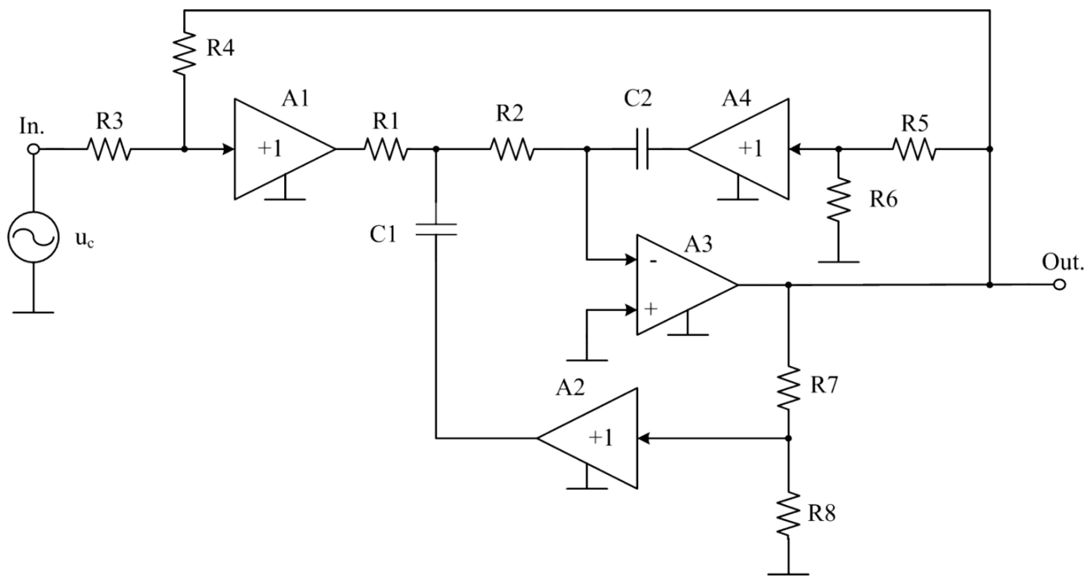
Figure 1 shows the scheme of the proposed low-pass filter [
3], which can be considered as a modification of the well-known low-pass filter circuit described in [
4]. A feature of the circuit in
Figure 1 is that it provides for independent adjustment by different resistors of the transmission coefficient, pole frequency and quality factor of the pole. At the same time, the circuit provides a low sensitivity of the transmission coefficient to various destabilizing factors - tolerances on the parameters of the frequency-setting elements of the circuit and changes in their characteristics due to temperature or radiation.
Consider the operation of the proposed LPF
Figure 1. As a result of mathematical analysis of the circuit at τ
1 = R
1C
1, τ
2 = R
2C
2 it can be shown that:
- LPF transmission coefficient at zero frequency
- LPF transmission coefficient at the pole frequency
Analysis of formulas (1) - (4) shows that the independent setting of the circuit parameters can be performed in the following sequence
- with the help of resistors R3 and R4, the transmission coefficient at low frequency is adjusted (formula (1)). Further, these resistors are not used to adjust other circuit parameters;
- resistors R5 and R6 adjust the frequency of the pole (formula (3)). Further, these resistors are not used to adjust the attenuation of the pole;
- with the help of resistors R7 and R8, the attenuation of the pole is adjusted (formula (4)).
Due to the fact that the transmission coefficient at low frequency (1) is determined by the ratio of two resistors and does not depend on the parameters of other circuit elements, its high stability is achieved with various destabilizing factors.
On
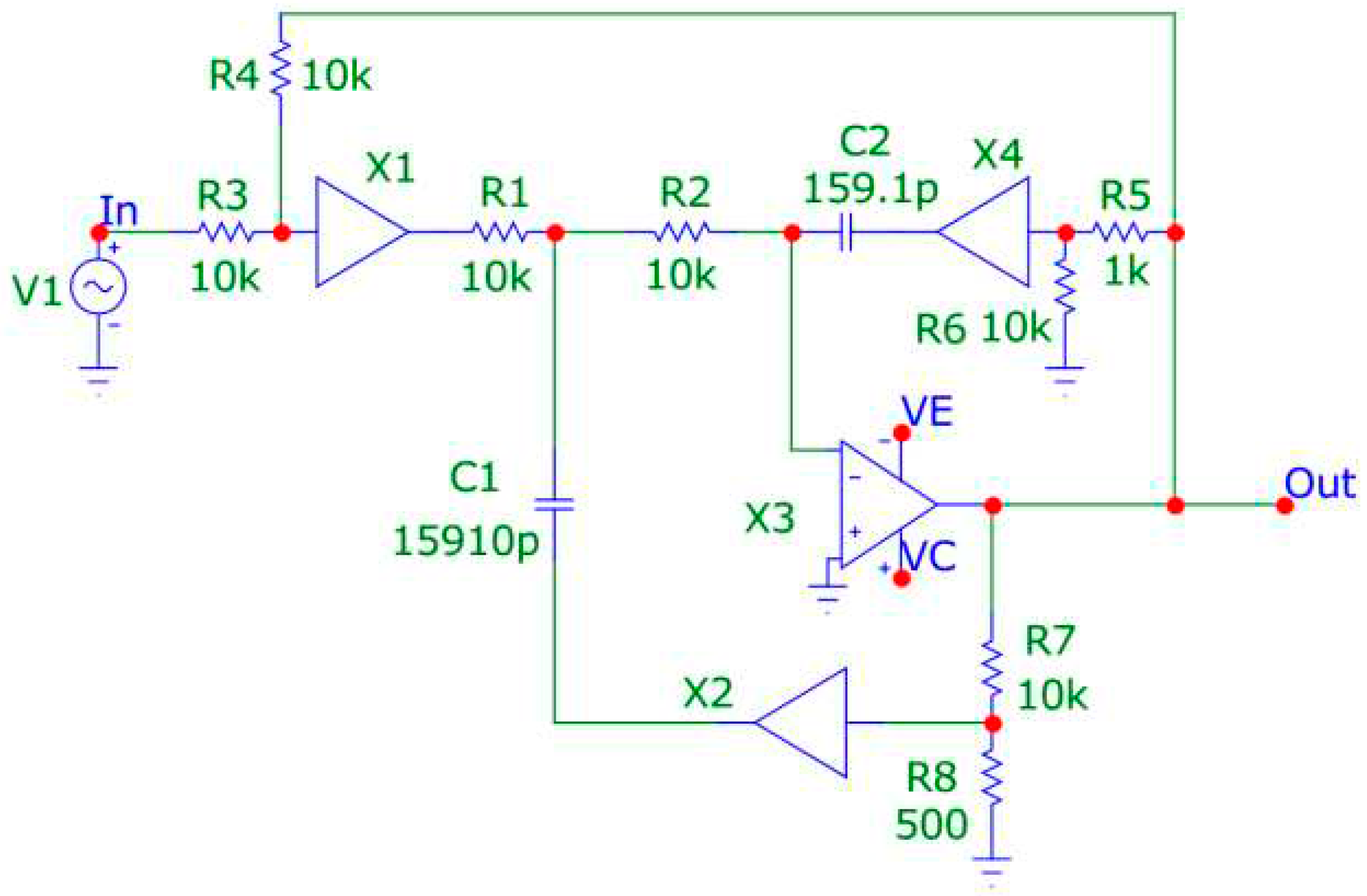
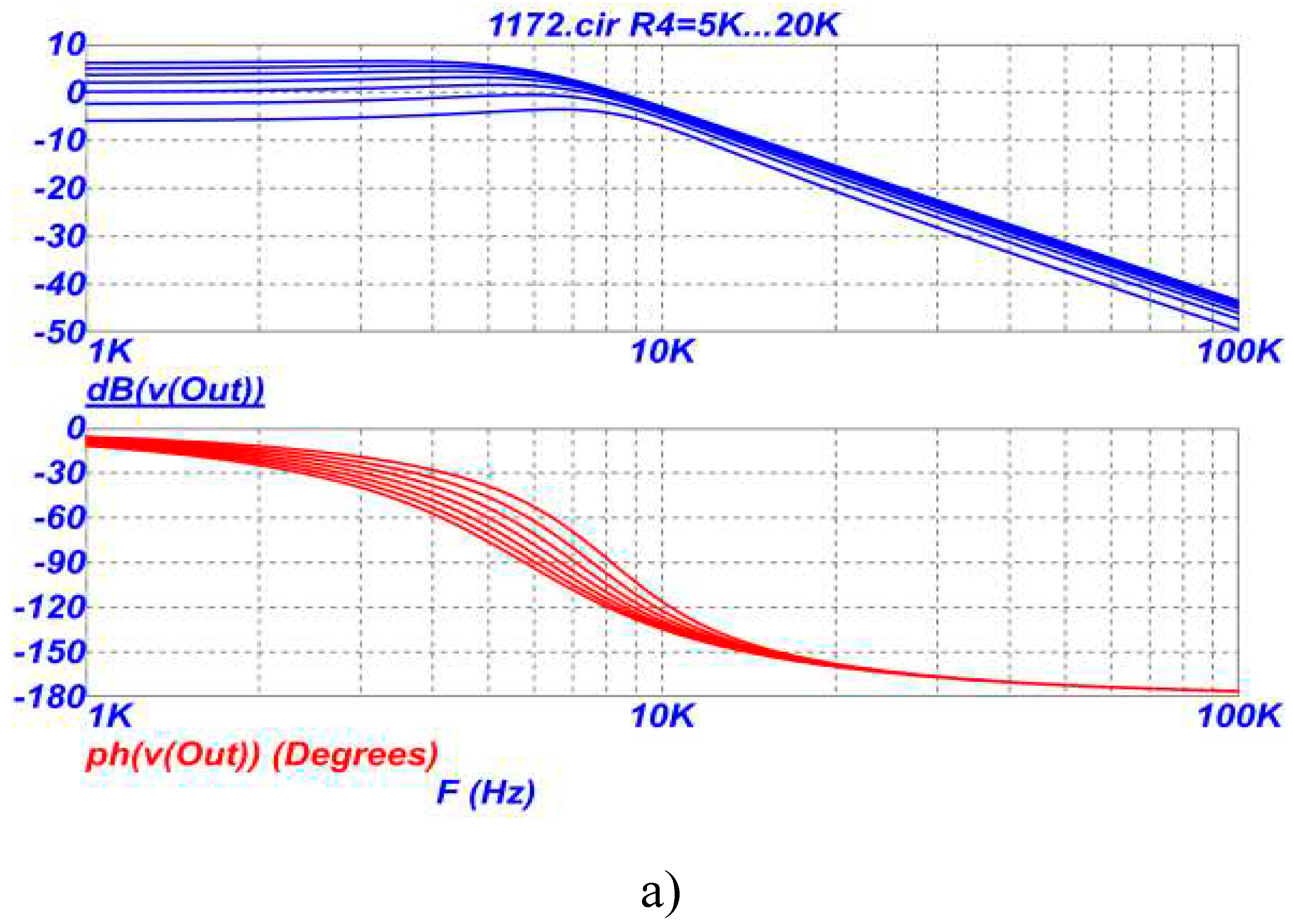
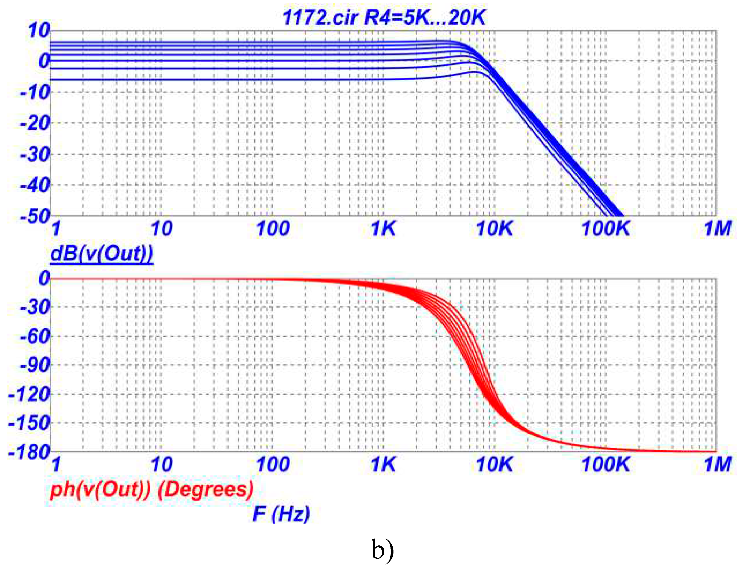
Figure 3 shows the amplitude-frequency (AFC) and phase-frequency (PFC) characteristics of the LPF on
Figure 2 in the region of the pole frequency (a) and a wider frequency range (b) when the resistance of the resistor R4 changes in the range of 5-20 kOhm.
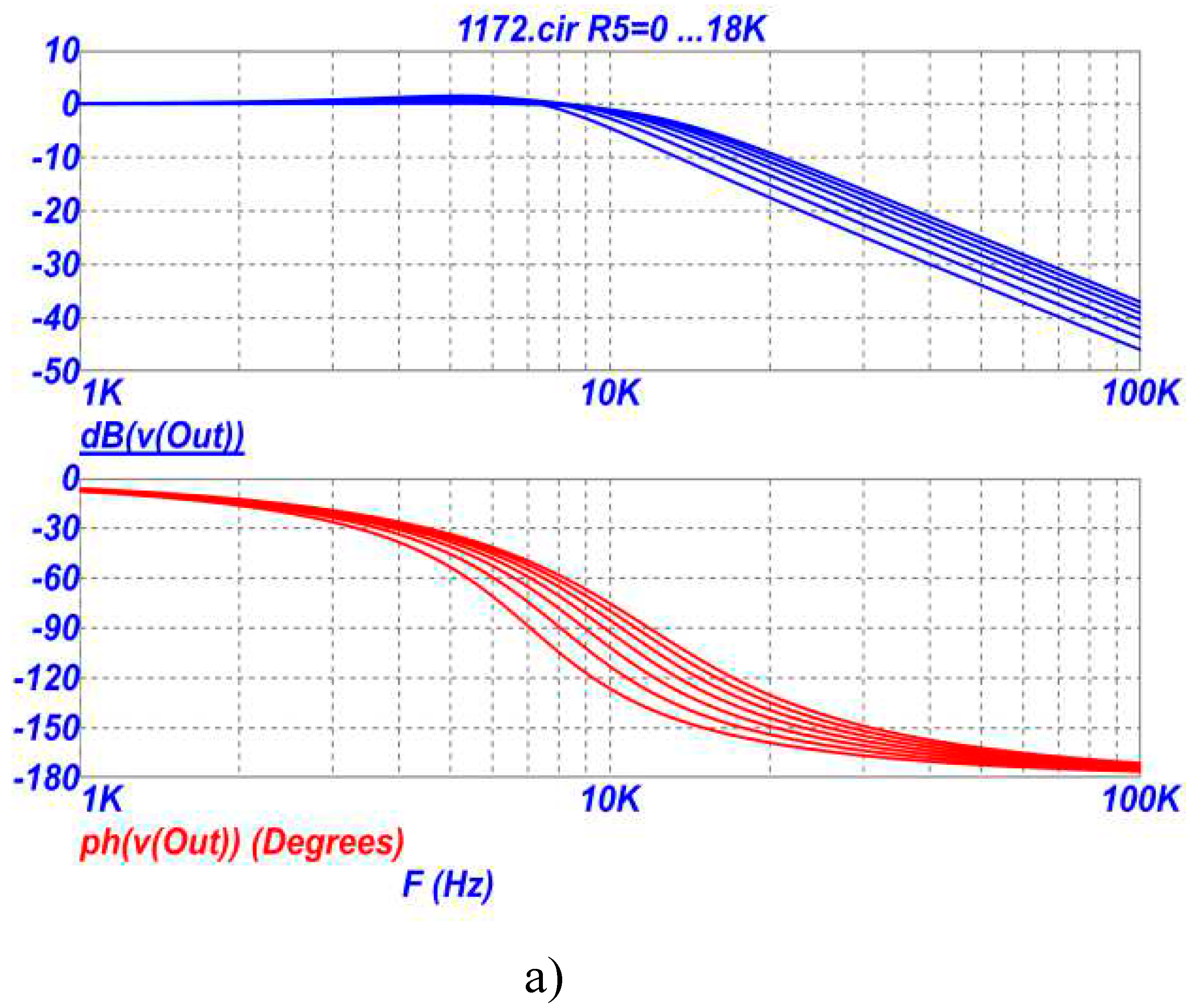
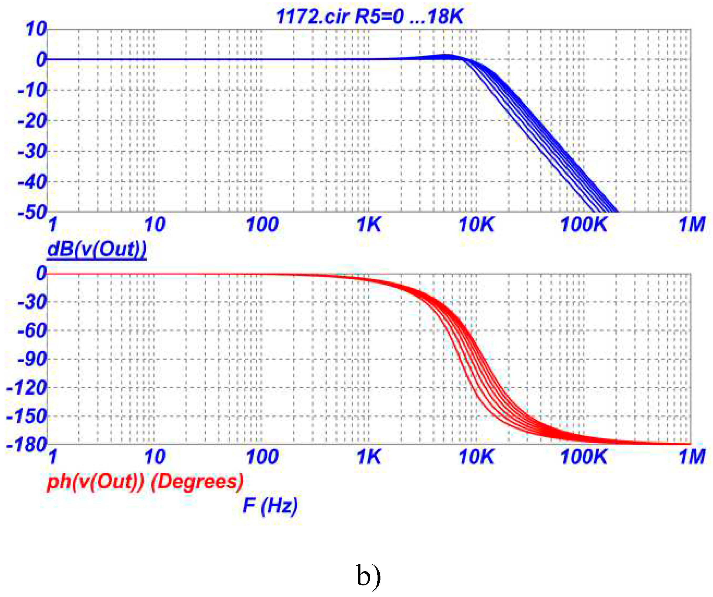
On
Figure 4 shows the frequency response and phase response of the LPF on
Figure 2 in the region of the pole frequency (a) and a wider frequency range (b) when the resistance of the resistor R5 changes in the range of 0-18 kOhm.
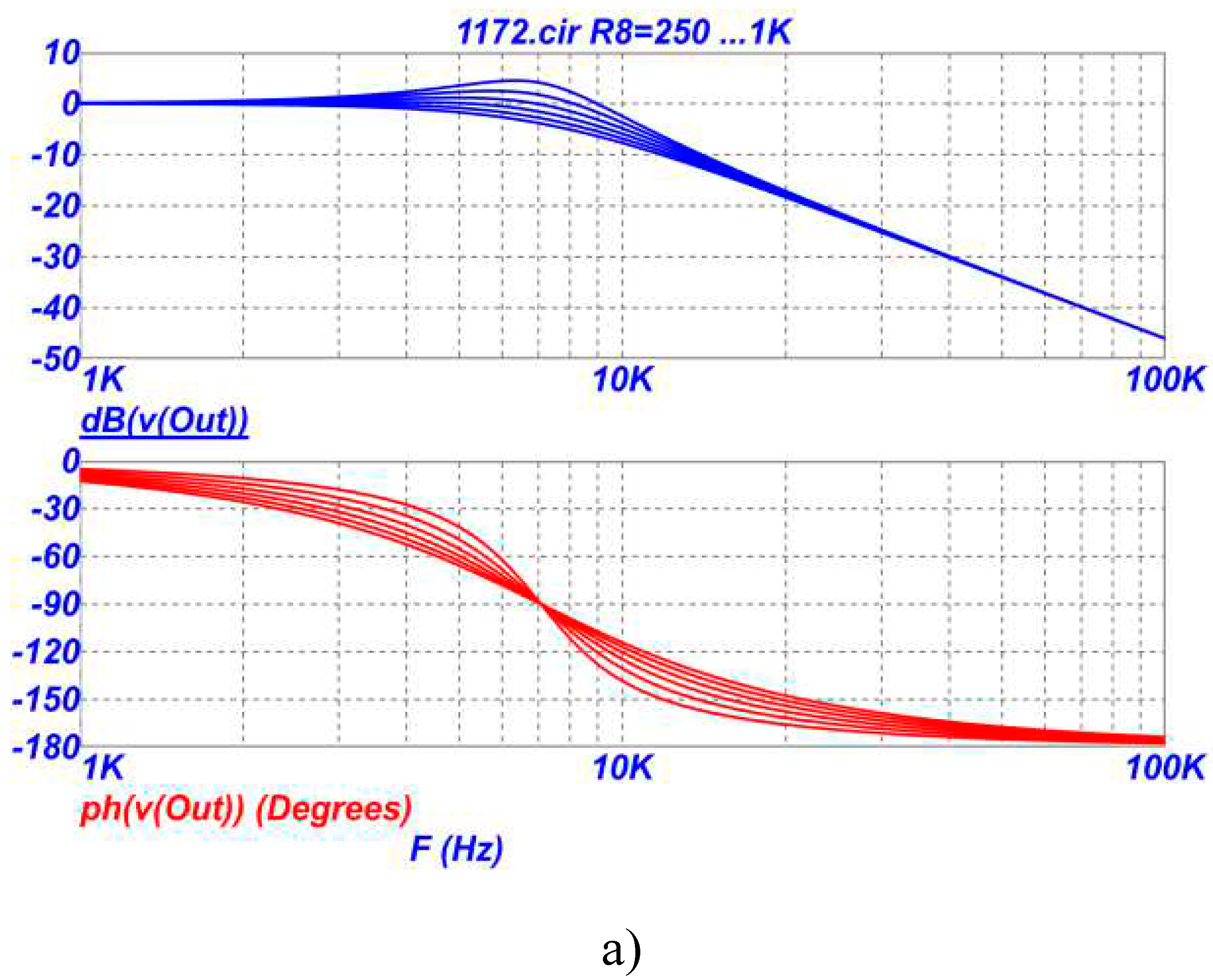
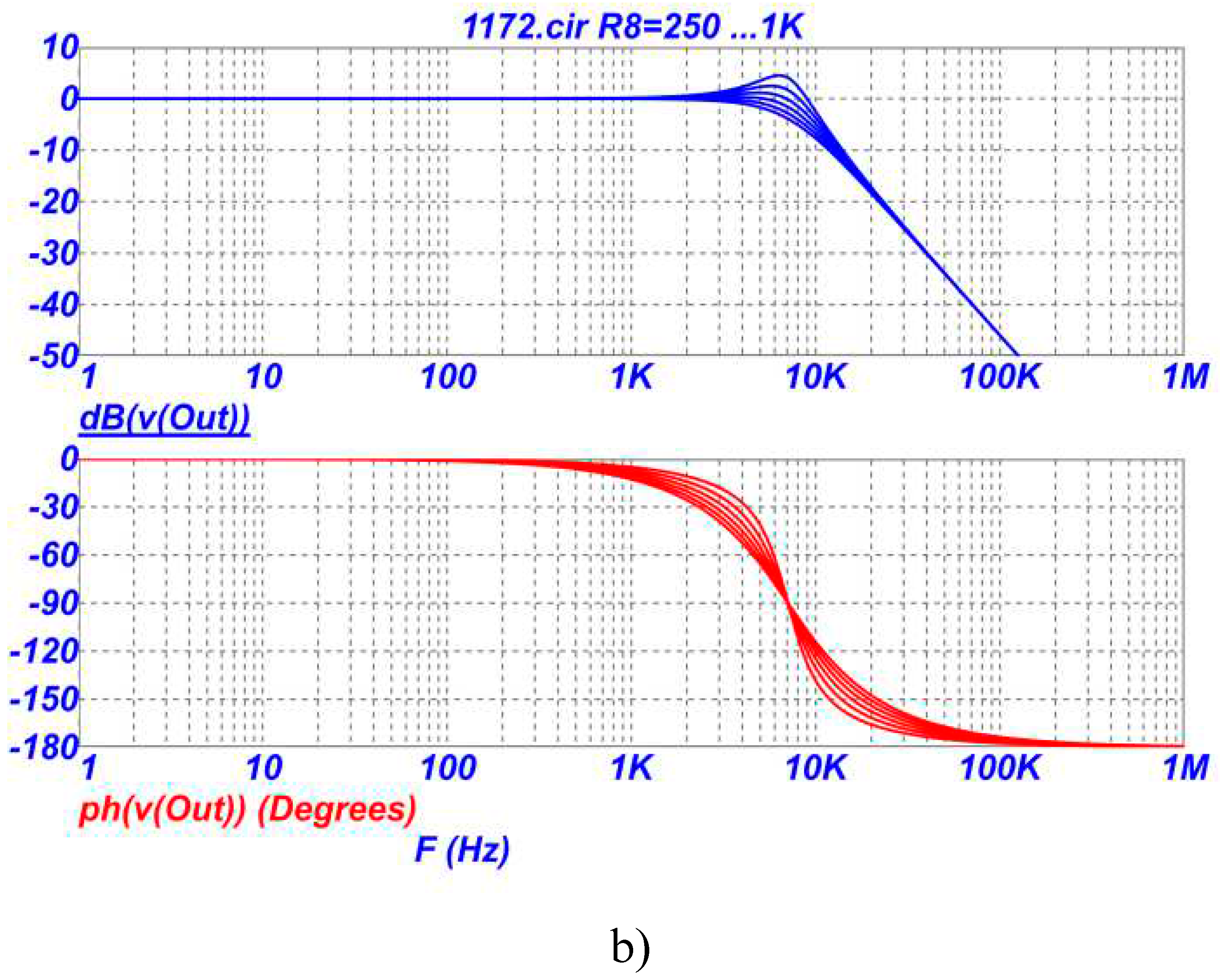
On
Figure 5 shows the frequency response and phase response of the LPF on
Figure 2 in the region of the pole frequency when the resistance of the resistor R8 in the range of 0.25-1 kOhm.
From the analysis of the graphs in
Figure 3,
Figure 4 and
Figure 5 it follows that in the proposed LPF it is possible to independently adjust and adjust the parameters with different resistors in the following sequence: transmission coefficient - by changing the resistances of resistors R3 and/or R4, pole frequency - by changing the resistances of resistors R5 and / or R6, attenuation poles - by changing the resistances of resistors R7 and / or R8. Graphs on
Figure 3 (a,b) show that the gain can be set either less or greater than unity (less or greater than 0dB). At the same time, the sensitivity of the transmission coefficient to changes in the parameters of other elements of the circuit remains extremely low and equal to zero, i.e. the transmission coefficient of the low-pass filter depends only on the ratio of the resistances of the two resistors R3 and R4 (see formula (1)). It should also be noted that by choosing the numerical value of the ratio of resistors R3 and R4 according to formula (1), in the low-pass filter circuit, the transfer coefficient can be realized either more or less than unity.
3. Conclusion
A new circuit of an anti-aliasing low-pass filter for the problems of analog-to-digital signal conversion has been developed and studied, in which an independent, incl. digital, basic parameter setting. In this case, the LPF transmission coefficient can be set either less or greater than one (less than or greater than 0dB), and the sensitivity of the transmission coefficient to changes in the parameters of the frequency-setting elements of the circuit remains extremely low and equal to zero.
Funding
The research has been carried out at the expense of the Grant of the Russian Science Foundation (project No. 18-79-10109-P).
Conflicts of Interest
The author declares no conflict of interest.
References
- Moschytz, George S. Analog Circuit Theory and Filter Design in the Digital World: With an Introduction to the Morphological Method for Creative Solutions and Design. Springer, 2019, 551 p. [CrossRef]
- Samoilov L.K., Denisenko D.Yu., Prokopenko N.N. Monograph. Dynamic errors of the process of inputting analog signals of sensors in automatic control and monitoring systems, Moscow, SOLON-Press publishing, 2021. ; 240 p. [Online]. https://elibrary.ru/item.asp?id=46231795 (accessed on 23 Mar. 2023).
- D.Yu. Denisenko, N.N. Prokopenko, I.V. Pakhomov, “Low-pass filter,” RU Patent application 2023105432, Publicated: March 9, 2023. (In Russian).
- N.N. Prokopenko, P.S. Budyakov, A.V. Bugakova, D.Yu. Denisenko “Sallen-ki subclass low-pass filter with independent adjustment of the main parameters,” RU Patent 2784375, Publicated: November 24, 2022. (In Russian).
|
Disclaimer/Publisher’s Note: The statements, opinions and data contained in all publications are solely those of the individual author(s) and contributor(s) and not of MDPI and/or the editor(s). MDPI and/or the editor(s) disclaim responsibility for any injury to people or property resulting from any ideas, methods, instructions or products referred to in the content. |
© 2023 by the authors. Licensee MDPI, Basel, Switzerland. This article is an open access article distributed under the terms and conditions of the Creative Commons Attribution (CC BY) license (http://creativecommons.org/licenses/by/4.0/).
