1. Introduction
Aqueous foams are defined as a high volume fraction of gas bubbles in a small part of liquid [
1]. They have recently been studied in different accepts due to their applications in industries such as cosmetics, oil recovery and deliquification of natural gas [
2,
3,
4,
5].
There have been many types of research in different accepts for the understanding of the dynamic of the foam and the flow in the films, such as drainage properties, surfactant materials, surfactant concentration, and Marangoni effect [
6,
7,
8]. The Marangoni effect was named after Carlo Giuseppe Matteo Marangoni, introduced this flow during his doctorate thesis in 1865 [
9]. The gradient of surface surfactants concentrations creates Marangoni flow [
10], they are the chemical components and solvable in water [
11,
12] with the complex molecular shape. Surfactants can occupy the free surface by their head and decrease the surface [
13]. Marangoni flow can occur in different ways such as recirculation, photo-surfactant, and foam fractionation. The first model for recirculation counterflow due to the Marangoni effect in the region of the film close to the Plateau Border (PB) was introduced by Pitois et al. [
14]. Marangoni due to photo-surfactant is caused by the UV light, which was investigated by Chevallier et al. [
15]. They have investigated the effect of UV light on the drainage of thin aqueous films.
Foam fractionation is a high-speed process which is based on the fast raise of surfactant concentration in foam column [
16,
17]. In this process, a Reflux system has a main role in rising the column with the surfactant, which means a part of the foam could return to the top of the column and let the column be uniformly enriched by surfactant concentration in PB [
16,
18]. Foam fractionation has many applications in industry such as removing contaminations from wastewater and protein skimmers. In protein skimming the hydrophobic molecules can be removed from the liquid solution by reflux system [
19]. During the foam fractionation, the reflux process does not change the surfactant concentration of the films immediately, however, the surfactant can flow from PB to lamella [
7,
20]. This surfactant diffusion to the film could be done by extra force (Marangoni flow) which is due to the surfactant gradient in the interface [
21,
22]. Drainage is another important flow in foam fractionation which help in surfactant transportation in film and it is in the inverse direction of Marangoni flow from film toward the PB due to the lower pressure in PB [
21], it is also defined as a hydrodynamic process with various effective factors [
23,
24,
25]. However, in this study, we only focus on the Marangoni flow, and optimizing the parameters can help the performance of the fractionation column. In the foam fractionation, the value of PB is set to the value of the foam fractionation column which is unchanged during the fractionation. Therefore, the value of the fractionation column can affect the velocity profile of the Marangoni flow in the transitional area.
In this study, the focus is on investigating the Marangoni flow in foam fractionation, specifically optimizing the parameters to enhance the performance of the fractionation column. The influence of the initial surfactant concentration of the PB on the Marangoni velocity profile is investigated by changing the ratio of surfactant concentration in the reflux column or PB to the surfactant concentration of the film center. The relation of Marangoni velocity with is also studied for varying values between 1.5 to 3. Additionally, the influence of the Boussinesq number(Bo) on Marangoni flow is studied for a wide range of values including slip and rigid walls. The study also investigates Marangoni flow in the exterior film where bubbles are in contact with walls and compares it with the interior film. Finally, the influence of various Bo numbers on the flow behavior in the exterior film is also studied.
2. Model geometry and Methodology
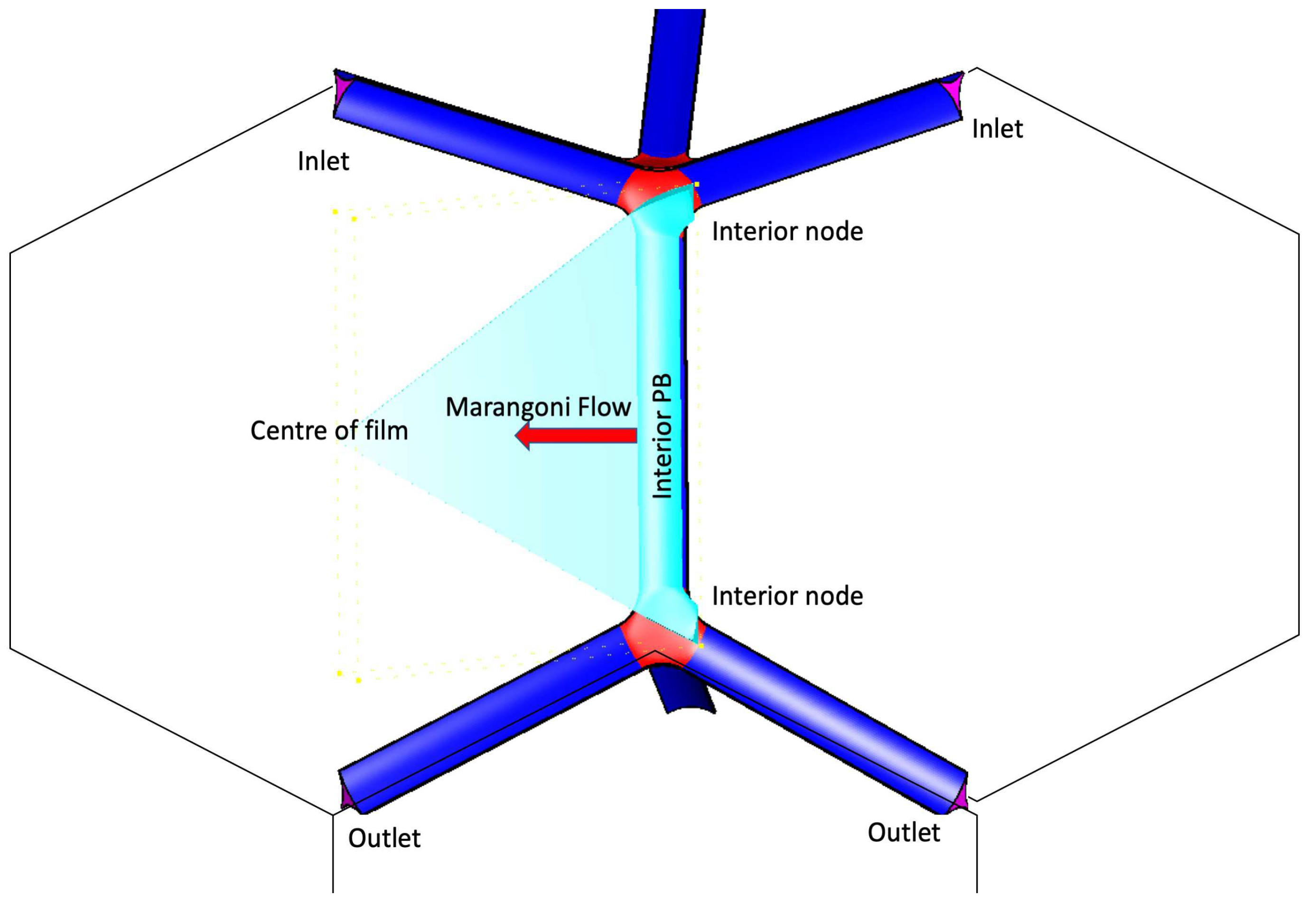
For this study, a three-dimensional geometry of a dry micro-scale foam containing PB’s, nodes, and films is used. The simulations are based on volume-approached models that are applied to the interior and exterior of the micro-foam geometry. Interior foams are formed in the interstitial region between the three neighboring bubbles, while exterior foams are formed in the region between the two neighboring bubbles and a rigid container wall. The conjunction with the exterior wall led to a change in the geometry of the exterior foams. The geometries are considered for the tetrakaidecahedral shape of the bubbles with the sixfold symmetry assumption as illustrated in
Figure 1.
In this study, the film width (including PB width) is set to
, the transverse radius of curvature is
, and the film thickness is
. It is important to note that the film thickness is assumed to be constant during all simulations. The symmetry areas of the geometries are illustrated as sky blue-colored regions in
Figure 1, and the arrow key in
Figure 1 is representative of the Marangoni flow direction from PB to the center of the film.
The model methods are based on the Eulerian frame of reference and utilize a cell-centered finite volume approach for discretizing the governing equations. The exterior and interior geometries are created using GAMBIT software and imported into AVL FIRE 2017.0 commercial software. The interior and exterior geometries consist of 99,656 and 78,448 cells, respectively.
3. Theoretical model
The simulation of the flow is based on the time-dependent three-dimensional Navier-stokes equations. To account for time-dependent effects, we consider a time-transient simulation. The governing equations of the system in the Euler frame will be the conservation of mass, momentum, and passive scalar as following as:
Momentum conservation:
where
v,
p and
are the fluid velocity, static pressure and the gravitational body force, respectively.
In this study the surfactant concentration is governed by the passive scalar conservation law (surfactant mass balance) [
26,
27,
28,
29].
where (
),
, and t represent surface surfactant concentration, the velocity on the surface, and time, respectively. The gradient operator was the surface gradient operator due to the definition of (
), which is considered on the surface.
3.1. Boundary conditions
The boundary conditions applied on the geometry of our Marangoni flow model for foam fractionation in the lamellar film are as follows:
1. The fluid is assumed to be laminar, Newtonian, and incompressible without any turbulence. The flow is modeled as unsteady with a time-step of 0.001 to accurately simulate the dynamics of the system.
2. The sixfold symmetry is chosen for the flow across the net in the Geometrical model, as shown in
Figure 1, to ensure a more realistic and precise representation of the foam fractionation process.
3. The surface concentration of surfactant on the PB is assumed to be constant. To model the interface of liquid and air for PB, the following equation is applied:
where
and
are the surface viscosity and the bulk viscosity, respectively. The normal and tangential coordinates of the air-liquid interface are represented by N and s, respectively.
4. The liquid-air interface equation coupled with Marangoni flow is applied to model the behavior of the film, using the following equation:
The third term in the equation is the definition of the Marangoni stress, which is:
where
represents the tangential surface surfactant concentration gradient, and
is the Gibbs elasticity [
12,
30].
5. The thickness of the film is assumed to be fixed along its length [
31].
These boundary conditions were critical in accurately modeling and analyzing the behavior of the Marangoni flow in both the interior and exterior of the micro-foam and evaluating the effects of surfactant concentration and interface mobility on the flow velocity in the film.
4. Results and discussion
In this study, the behavior of the flow from PB to the film was investigated with greater accuracy by utilizing a three-dimensional model, which has fewer limitations than the previous two-dimensional models. Sodium Dodecyl Sulfate (SDS) was selected as the material for initial simulations, with a Bo number of 0.5. The primary goal of this research was to explore the parameters that can affect the Marangoni flow during foam fractionation, with the ultimate aim of enhancing the model and developing a better understanding of foam fractionation in the reflux system.
The simulation parameters were based on previous studies [
7,
14,
32], as summarized in
Table 1. The Marangoni flow variation over time was examined for different initial conditions, such as varying initial ratios of PB to film surfactant surface concentration. Additionally, the impact of Bo numbers on Marangoni flow for both interior and exterior geometries was investigated.
In this study on foam fractionation, the quantities required for calculations were scaled to their non-dimensionless values (as presented in
Table 2). The length parameter of the film (Y) was scaled by the length of the film from PB to the center of the film; the normalised length was denoted by
. The velocities were scaled by
, where
represented the gravity force in the system, and
A and
represented cross-section area and bulk viscosity. The scaled surfactant concentration was denoted by
, which was defined as
. The non-dimensionless factor for time was
, where
L,
G and
were the half-length of the film, Gibbs number and half-thickness of the film. The scaled time was presented as
.
4.1. Marangoni velocity evolution
The simulations are based on the assumption of no film thinning and a fixed film thickness; therefore, the interface is determined only by the Marangoni stress. As a result, during the early times, the surface surfactant concentration on the film increases with time due to a surface concentration gradient between the PB and the film, resulting in the Marangoni flow. This flow pushes the amount of surfactant to transport toward the film center as time progresses. Marangoni velocity is more easily detected when there is a higher surface tension gradient. Therefore, early times are defined as the times before the surfactant surface concentration reaches halfway or when Marangoni velocity is more easily detected. Equilibrium value corresponds to a constant surfactant surface concentration that is established due to the presence of reflux material in the PB.
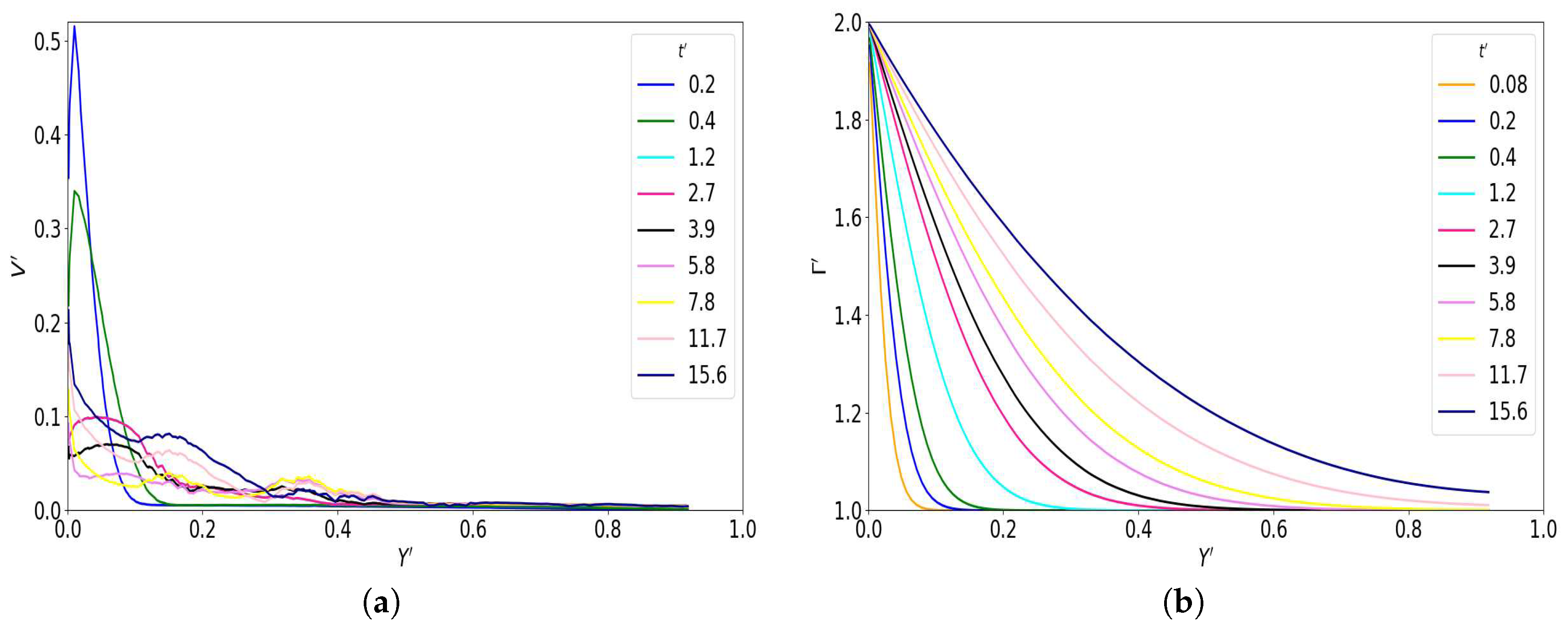
The evolution of both surfactant surface concentration and Marangoni velocity is shown in
Figure 2. In
Figure 2a, the transformation of the surfactant from the PB to the center of the film is shown during the early times.
In
Figure 2b, the Marangoni velocity is investigated over time. As shown, the maximum Marangoni velocity occurs at
= 0.2 for the location (
) near the PB. These peaks shift to a lower value of velocity and a higher value of
over time. This means that, as time progresses, the velocity profile peaks dampen toward the center of the film.
corresponds to the time when the surfactant surface concentration in the film center reaches the surfactant concentration value in PB. In our simulation, is approximately 3 seconds (or = 110 units) when is equal to the surfactant concentration of the reflux column (if is chosen to be and is chosen to be , then would be 2).
Vitasari et al. [
7] have measured the final equilibrium time to be 0.14 seconds or
= 4.47 in dimensionless scale. As investigated by Martin et al. [
16], the typical
varies from minutes to hours in a foam fractionation experiment, depending on the size of the foam, thickness, and surfactant concentration of the reflux columns.
Therefore, in Vitasari et al.’s study [
7], the surfactant on the film surface reaches the equilibrium point in a very short time in the absence of film thinning. Comparing our method with the analytical analysis of Vitasari’s study shows that our method needs a longer time to reach the equilibrium point, which is closer to the experimental range introduced by Martin et al. [
16].
4.2. Influence of reflux column surfactant concentration on Marangoni flow in film
The reflux column plays an important role in the foam fractionation process as it separates materials from the liquid. This method involves a feeding source that injects a higher concentration of surfactant into the foam, resulting in higher surfactant concentration in the PBs [
33]. Due to the fast continuous feeding process, there is no surface tension gradient in the PBs. However, there is a surface tension gradient between the reflux-enriched PBs and the films, which depends on the concentration of the surfactant in the PBs and the chosen chemical surfactant [
34]. Therefore, changing the amount of surfactant in the reflux column
influences the
and consequently Marangoni flow. The mobility of the interface or Bo number of the liquid also plays an important role in Marangoni flow, which will be investigated in the next section.
Here, we studied the effect of different values of
, ranging from
to
, which are lower than the maximum surface excess for SDS (
) [
34]. It should be noted that in this study, surfactant diffusion is ignored, and therefore, the surfactant stays on the interface, not in the bulk of the film.
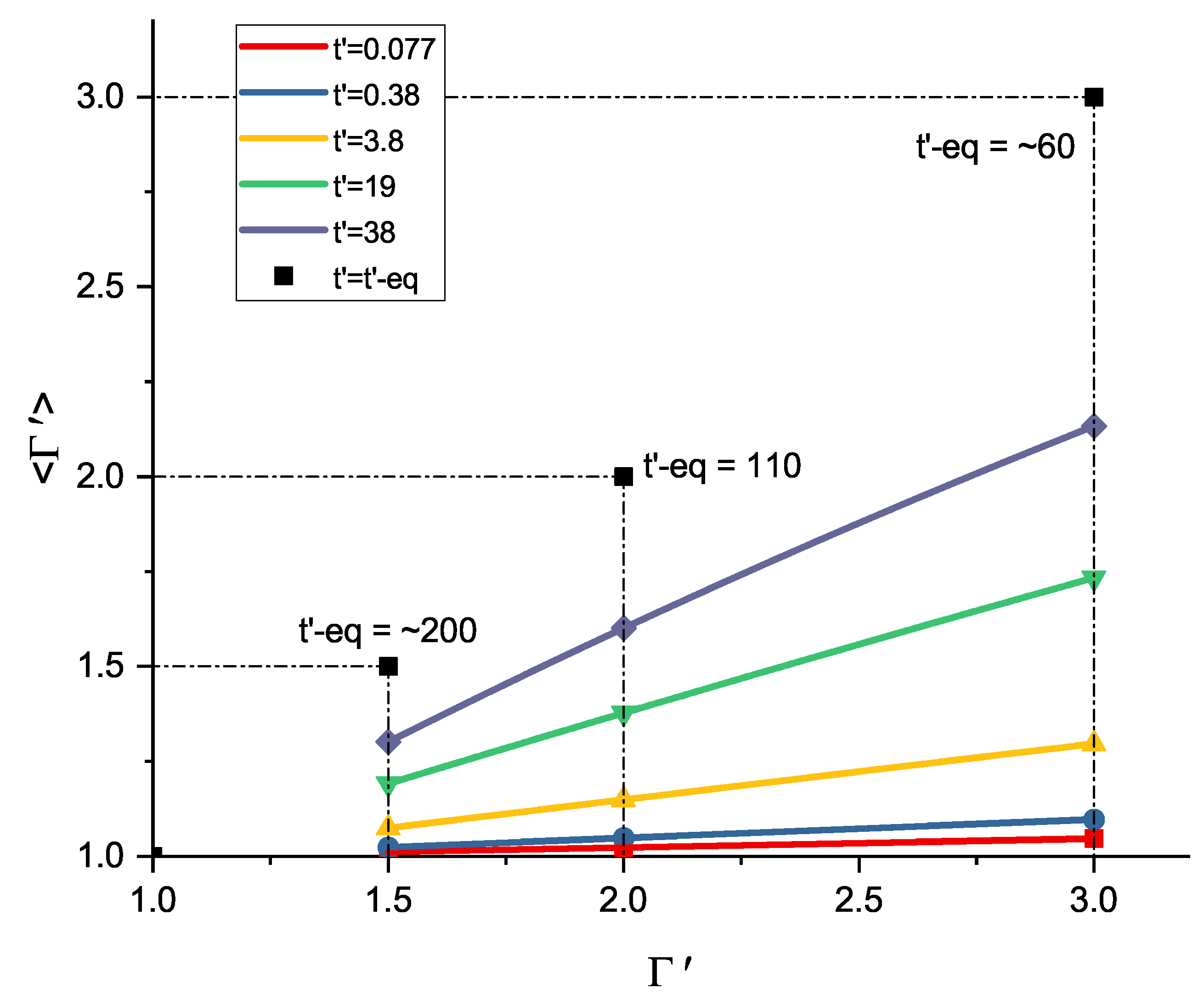
Figure 3 shows the evolution of the surfactant concentration for
. This figure illustrates how the average surfactant surface concentration
corresponds to the various reflux column concentrations. As shown, a higher amplitude of
causes a higher amount of surfactant excess to travel to the film, resulting in a higher Marangoni stress in the film.
Figure 3 also shows how
is related to the surfactant concentration in the reflux column, as more surfactant results in a faster equilibrium time.
Comparing the maximum Marangoni velocities for different
enables us to find a relation between
and
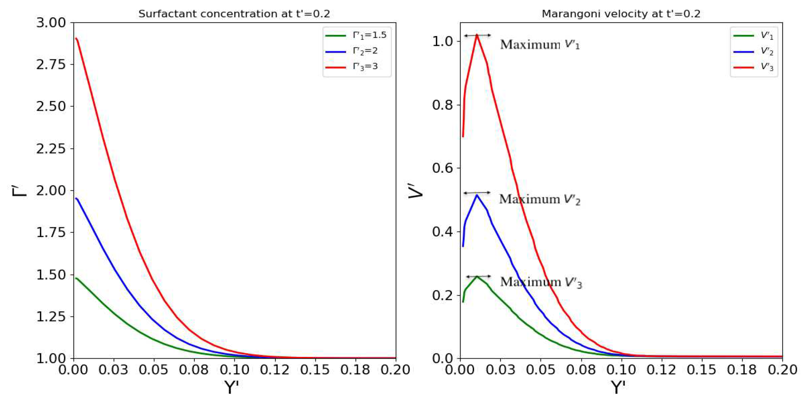
and, consequently, a better understanding of the reflux system and improvement of our foam fractionation model. Therefore, in
Figure 4, the maximum Marangoni velocities for
are compared. As shown, when
, the maximum Marangoni velocity
is 0.25 units, while the velocity value
for
is about 1 unit. Therefore, when
increases two times,
increases four times. Hence,
has a direct relation with
or
.
4.3. Marangoni flow in the interior and exterior films
An interior PB is an interstitial region between two neighboring bubbles, whereas an exterior PB is the region between a bubble surface and a no-slip flat container wall. Therefore, an exterior film with a thickness has two sides, one rigidly in contact with the wall and the other regarded as the liquid-gas interface. It should be noted that there are two types of interior films, one between two PBs perpendicular to an exterior PB, and the second between PBs not branching from the exterior PBs. In this paper, the latter type is studied and compared with the exterior film.
The change between exterior and interior geometries results in distinct differences in the flow behaviors in the interior and exterior of the foam due to different boundary conditions, such as the zero-velocity boundary condition (the zero-velocity area is at the intersection of the PB and film with the container wall).
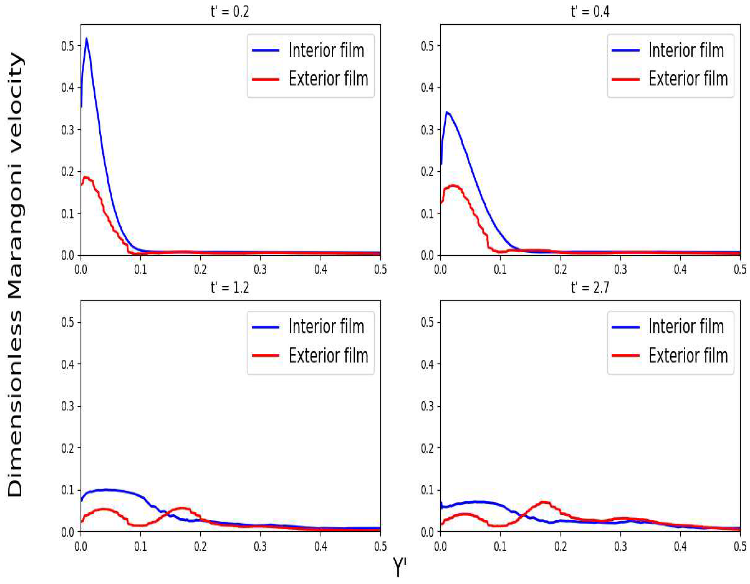
The behavior of Marangoni flow in the interior and exterior films is compared in
Figure 5 at different times. As shown, the difference is more evident at
and
, where the maximum velocity in the interior film is measured about three times more than in the exterior film. Over time, the Marangoni flow shows a different behavior in the exterior film. While the maximum velocity occurs at the beginning of the velocity profile (as a first peak) in the interior film, this trend in the exterior film occurs as a second peak of the velocity profile during later times at
and afterward (shown in
Figure 5).
This behavior is due to the presence of the wall, which can affect the velocity profile during foam fractionation, and also, the thickness of the film decreases in the exterior film.
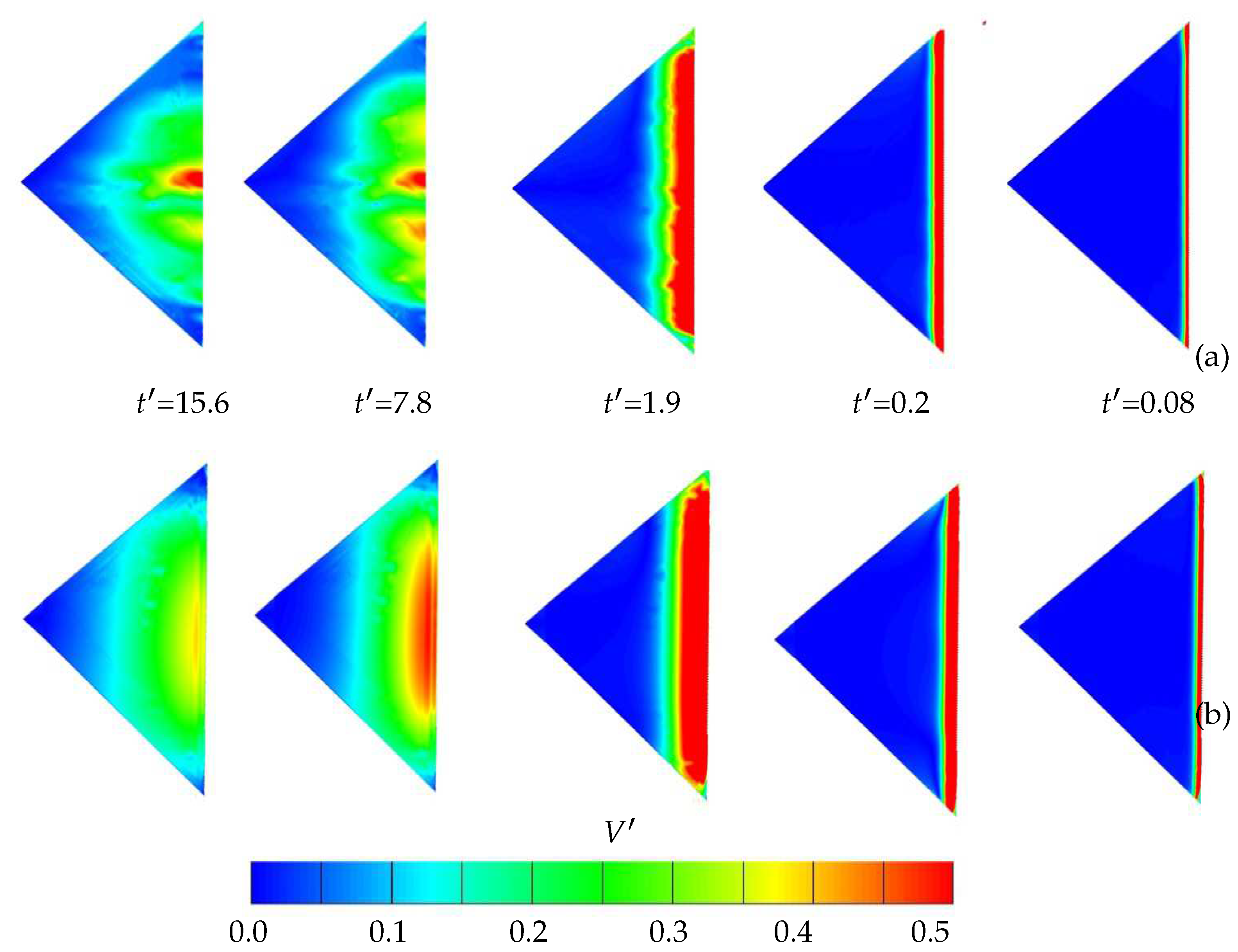
Figure 6 illustrates how the presence of a wall can affect the velocity profile during fractionation. In
Figure 6, the velocity profiles are shown for both interior and exterior films over time. The figure shows how the Marangoni velocities push the amount of surfactant to transport toward the film center as time increases. Therefore, the maximum Marangoni velocities shift toward the center of the film for both interior and exterior films, although they show a different trend in later times. The Marangoni velocity in the interior geometry has the highest value in the direction toward the film center, which can be seen at
in
Figure 6. However, for the exterior film, the velocity profile is widespread and not focused toward the film center due to the presence of the wall.
4.4. Influence of Bo number on the Marangoni film for both interior and exterior film
Different surfactant materials can result in different interfacial shear viscosity and surface mobility. The interfacial shear viscosity can be controlled by the Bo number, which is determined by the transverse radius of curvature of R, surface viscosity, and bulk viscosity. Hence, this study investigates the effect of Bo number as an indicator of interfacial mobility on the Marangoni velocity for both interior and exterior films during foam fractionation.
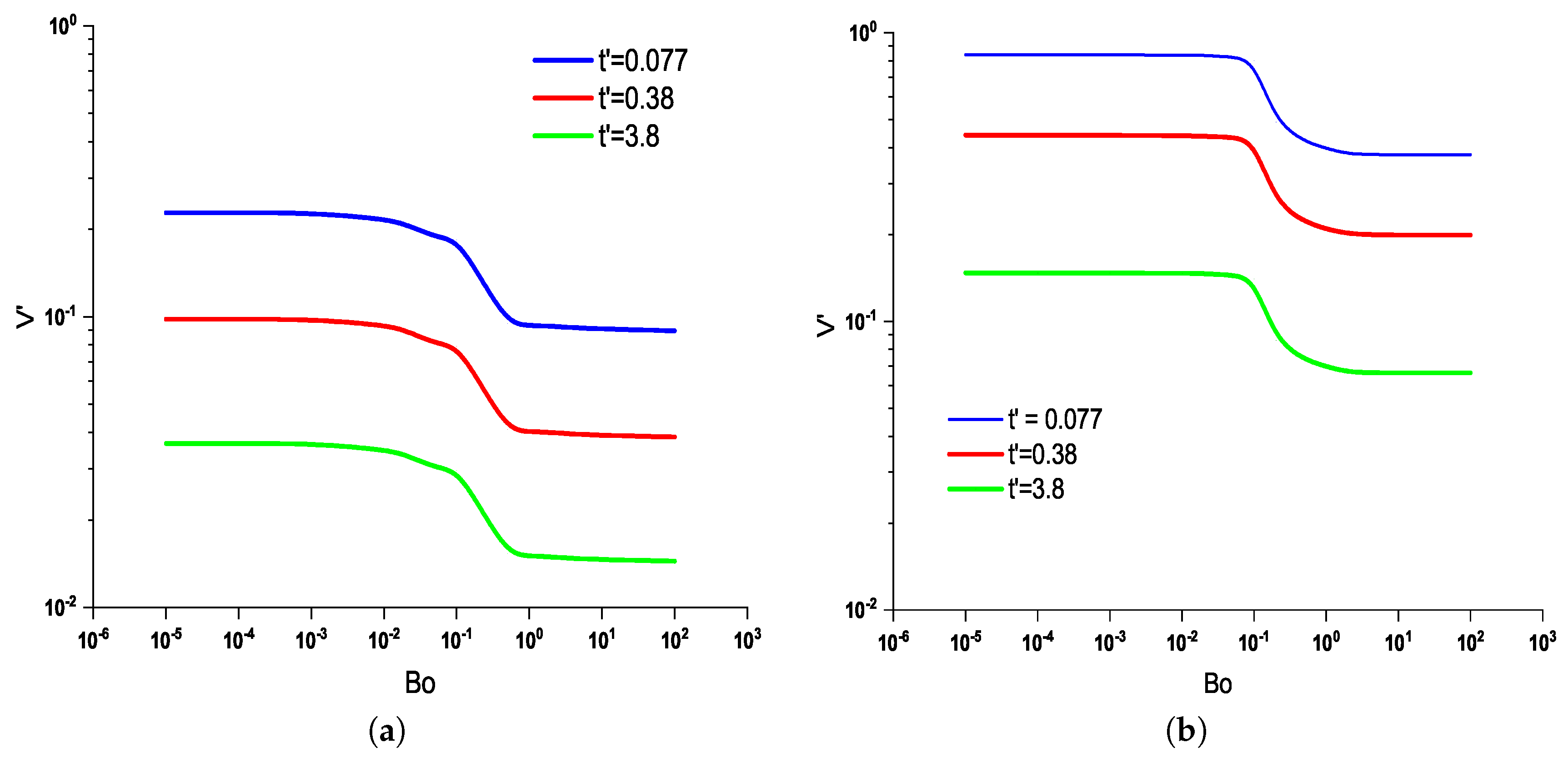
As Bo reduces, the mobility increases and the velocity decreases. This indicates that with the increasing mobility of the air-liquid interface or decreasing Bo number, the Marangoni flow increases.
Figure 7a,b investigate the influence of Bo number with surface mobility from rigid wall to slip wall (
) on Marangoni flow for the interior and exterior films, respectively.
As shown, the maximum Marangoni velocity occurs at
for the higher surface mobility (
) in both the interior and exterior films. However, for the interior film, the maximum variation of Marangoni velocity occurs for
, while for the exterior film, the higher variation of Marangoni velocity is observed for
, as shown in
Figure 7a, respectively.
Furthermore, the study reveals that the Marangoni flow exhibits the same trend with changing the Bo number over time, which is illustrated in both
Figure 7a,b for the selected times
,
, and
.
5. Conclusion
This paper presents a numerical investigation of the Marangoni flow during foam fractionation in a three-dimensional node-film-PB system for both interior and exterior films. Our findings indicate that while the velocity values decrease at the same rate over time in both systems, the Marangoni velocity is higher in the interior film. The presence of a wall and the thinned film thickness in contact with the wall cause the exterior film to behave differently from the interior film.
Furthermore, we studied the effect of the surfactant concentration of the reflux column on Marangoni flow in the interior film. Our results show that the initial value of the reflux column has a significant impact on the Marangoni flow from PB to the center of the film. The maximum Marangoni velocity is directly related to the chosen value of .
The mobility of the interface, which can be controlled by the Bo number, is another important factor that can affect the Marangoni velocity. We investigated the influence of Bo on the Marangoni velocity for both interior and exterior films. Our findings indicate that reducing the Bo number increases the Marangoni velocity, while increasing Bo or causing the interface to act as a rigid wall decreases the velocity. Moreover, the higher variation of the Marangoni velocity occurs for the range.
It should be noted that this study only considers Marangoni flow, and film drainage is not taken into account. Thus, future research could investigate the effect of film thickness and drainage on the behaviour of the flow in the three-dimensional film-node-PB system in both interior and exterior films.
Author Contributions
Conceptualization, R.N. and A.J.; methodology, R.N.; software, R.N. and A.J.; validation, R.N.; formal analysis, R.N.; investigation, R.N.; writing—original draft preparation, R.N.; writing—review and editing, R.N. , A.J. an N.J; visualization, R.N.; supervision, A.J. and N.J; All authors have read and agreed to the published version of the manuscript.
Conflicts of Interest
We declare there is no conflict of interest. We confirm that there is no role of the funders in the design of the study; in the collection, analyses or interpretation of data; in the writing of the manuscript; or in the decision to publish the results.
References
- A, B.; E, R. Adv Colloid Interface Sci 1997, 70, 1 – 124. [CrossRef]
- C, H.; J, E. Adv Colloid Interface Sci 2017, 247, 496 – 513. [CrossRef]
- RF, L.; W, Y.; SH, L.; GJ, H.; CA, M. SPE J. 2008; 15, 928–942.
- M, S.; Y, D.; A, A.; M, T.; PLJ, Z. Ind Eng Chem Res 2013, 52, 6221–6233. [CrossRef]
- J, Y.; V, J.; S, R. Colloids Surf, A 2007, 309, 177 – 181. [CrossRef]
- AV, N. J Colloid Interface Sci 2002, 249, 194 – 199. [CrossRef]
- D, V.; P, G.; P, M. Chem Eng Sci 2013, 102, 405 – 423. [CrossRef]
- Z, W.; G, N. J Colloid Interface Sci 2006, 300, 327 – 337. [CrossRef]
- JB, F.; AM, C. EPL, 1992; 20, 517.
- TG, M. SIAM REV 1998, 40, 441–462. [CrossRef]
- C, S., A Mathematical Analysis of Foam Films; Shaker Verlag GmbH, Germany, 2004; Vol. 1, chapter 1.
- P, G., Colloid and Interface Science; Prentice-Hall Of India Pvt. Limited, 2009; Vol. 1, chapter 2.
- A, B.; A, T.; N, K.; V, S. Adv Colloid Interface Sci 2015, 222, 670 – 677. [CrossRef]
- O, P.; N, L.; F, R. Eur phys j e 2009, 30, 27. [CrossRef]
- E, C.; A, S.J.; I, C.; F, L.; C, M. Soft matter 2013, 9, 7054–7060. [CrossRef]
- PJ, M.; HM, D.; JB, W.; S, B.; AB, R. Chem Eng Sci 2010, 65, 3825 – 3835. [CrossRef]
- Sherman, P. Surface and colloid science, vol. 10. Journal of Colloid and Interface Science 1980, 73, 300. [Google Scholar] [CrossRef]
- P, S.; GJ, J. Chem Eng Process 2007, 46, 1286 – 1291. [CrossRef]
- RA, L.; R, L. AIChE J 1965, 11, 25–29. [CrossRef]
- Anazadehsayed, A.; Rezaee, N.; Naser, J.; Nguyen, A.V. A review of aqueous foam in microscale. Advances in Colloid and Interface Science 2018, 256, 203–229. [Google Scholar] [CrossRef] [PubMed]
- D, V.; P, G.; P, M. Chem Eng Sci 2013, 102, 405 – 423. [CrossRef]
- P, G.; S, U.; MD, G.; D, V.; PJ, M. Chem Eng Sci 2016, 143, 139 – 165. [CrossRef]
- PM, K.; SI, K.; AV, N.; NG, V. Curr Opin Colloid Interface Sci 2008, 13, 163 – 170. [CrossRef]
- HA, S.; SA, K.; S, H.; M, D. J Phys Condens Matter, 2003; 15, S283.
- G, V.; D, W.; AM, K. J Phys Condens Matter, 1996; 8, 3715.
- Kallendorf, C.; Cheviakov, A.; Oberlack, M.; Wang, Y. Conservation laws of surfactant transport equations. Physics of Fluids 2012, 24. [Google Scholar] [CrossRef]
- Stone, H.A. A simple derivation of the time-dependent convective-diffusion equation for surfactant transport along a deforming interface. Physics of Fluids A: Fluid Dynamics 1990, 2, 111–112. [Google Scholar] [CrossRef]
- Slattery, J.; Sagis, L. Interfacial Transport Phenomena. Springer: New York, 2013. [Google Scholar]
- Wong, H.; Rumschitzki, D.; Maldarelli, C. On the surfactant mass balance at a deforming fluid interface. Physics of Fluids 1996, 8, 3203–3204. [Google Scholar] [CrossRef]
- Durand, M.; Stone, H.A. Relaxation Time of the Topological T1 Process in a Two-Dimensional Foam. Phys. Rev. Lett. 2006, 97, 226101. [Google Scholar] [CrossRef] [PubMed]
- Stewart, P.S.; Davis, S.H. Dynamics and stability of metallic foams: Network modeling. Journal of Rheology 2012, 56, 543–574. [Google Scholar] [CrossRef]
- A, A.; J, N. Chem Eng Sci 2017, 166, 11 – 18. [CrossRef]
- RA, L.; R, L. AIChE J 1965, 11, 18–25. [CrossRef]
- Chang, C.; Wang, N.H.; Franses, E. Adsorption dynamics of single and binary surfactants at the air/water interface. Colloids and Surfaces 1992, 62, 321–332. [Google Scholar] [CrossRef]
|
Disclaimer/Publisher’s Note: The statements, opinions and data contained in all publications are solely those of the individual author(s) and contributor(s) and not of MDPI and/or the editor(s). MDPI and/or the editor(s) disclaim responsibility for any injury to people or property resulting from any ideas, methods, instructions or products referred to in the content. |
© 2023 by the authors. Licensee MDPI, Basel, Switzerland. This article is an open access article distributed under the terms and conditions of the Creative Commons Attribution (CC BY) license (http://creativecommons.org/licenses/by/4.0/).
