Submitted:
27 March 2023
Posted:
28 March 2023
You are already at the latest version
Abstract
Keywords:
1. Introduction
2. Mathematical Foundation
2.1. IAG model in indicial formulation
2.2. IAG model in state-space representation
2.3. Adopted constants
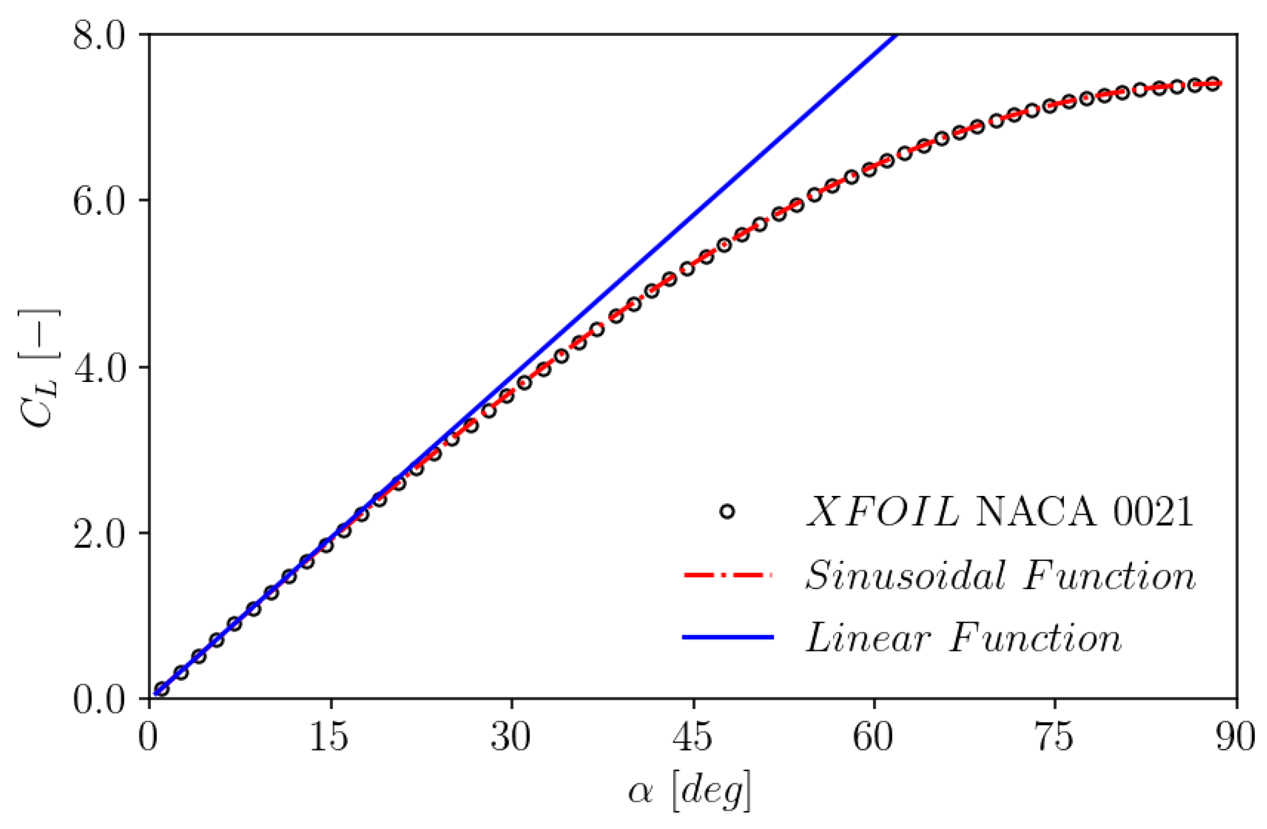
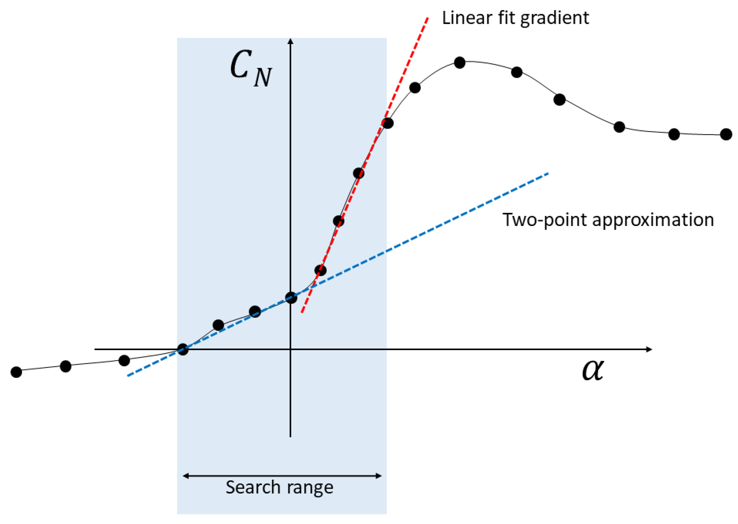
2.4. Automatic determination of the normal force gradient
3. Results and Discussion
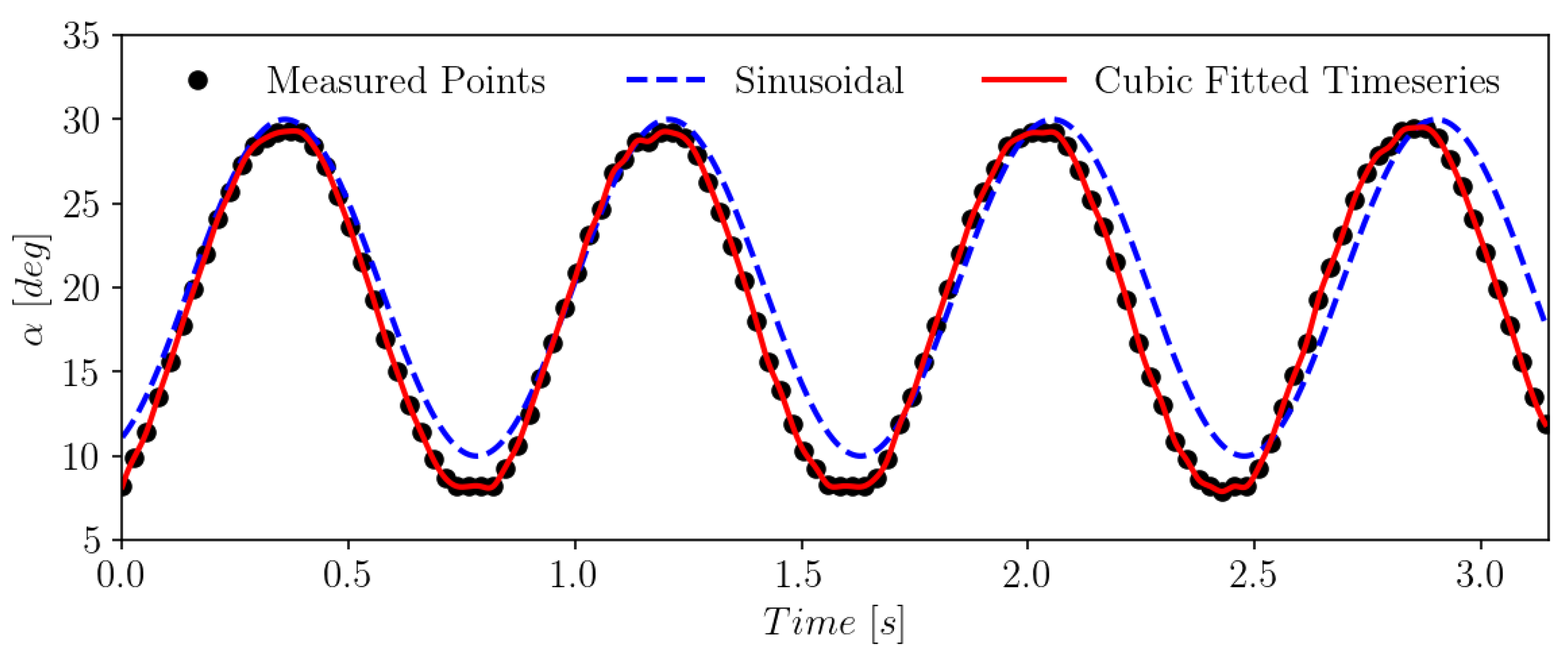
3.1. Test cases and treatment of the input data
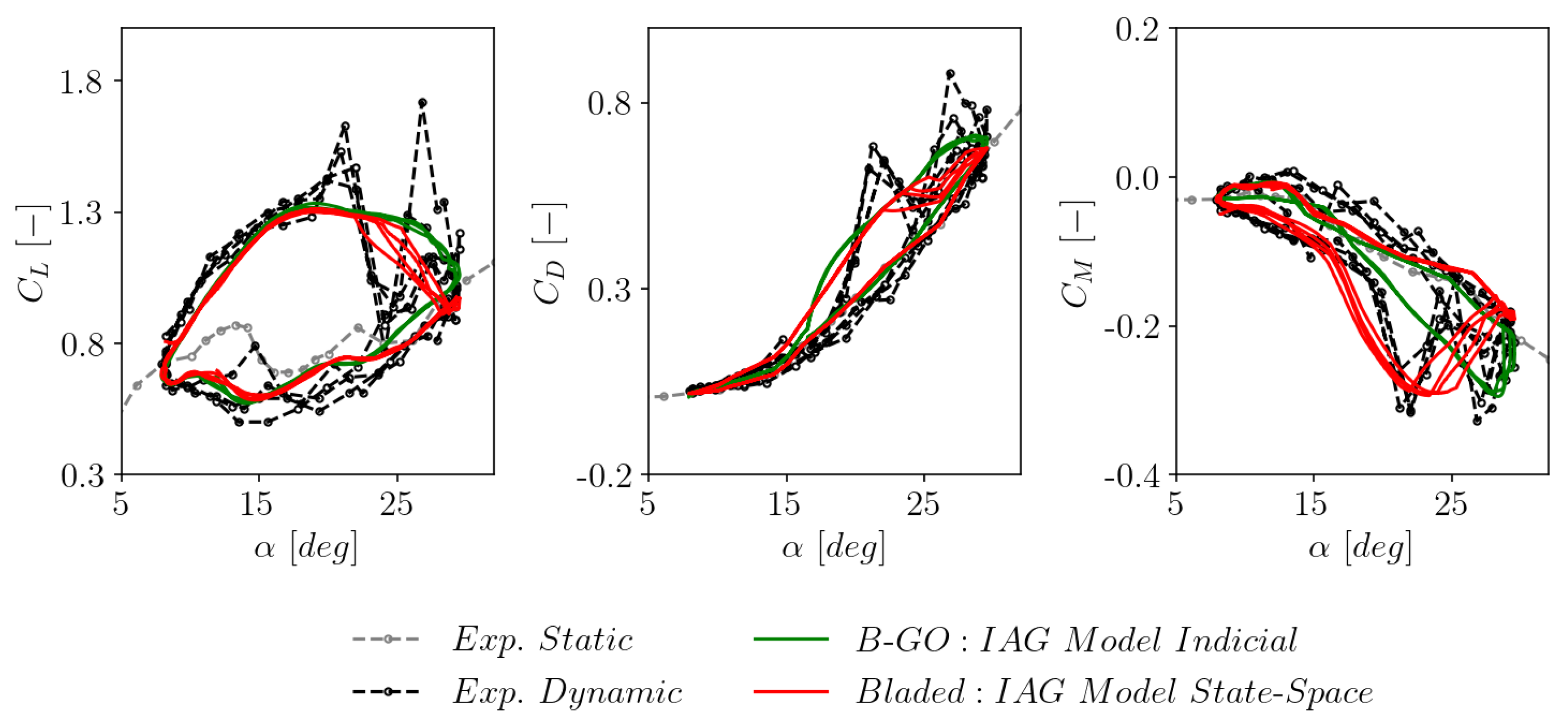
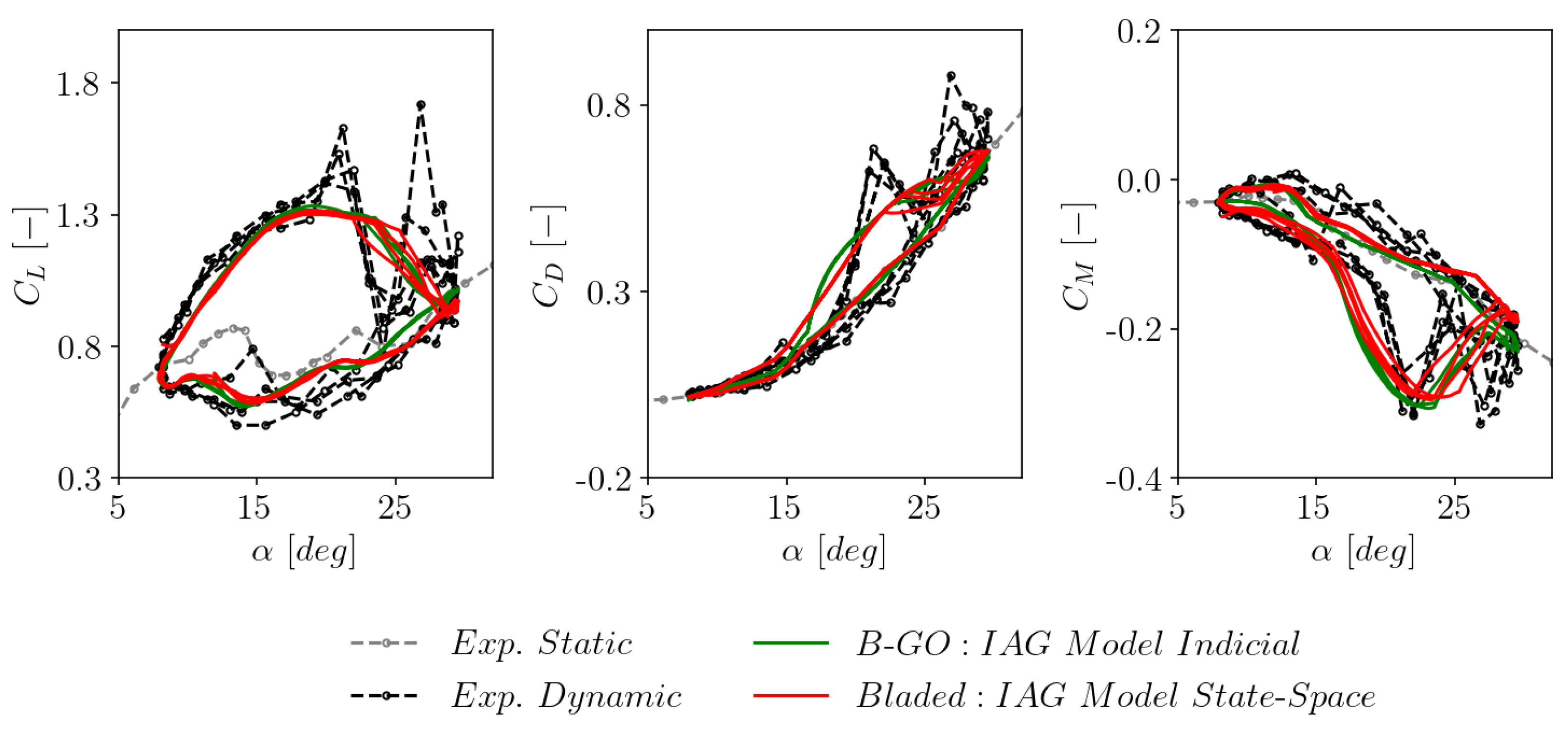
3.2. Consistency with the original indicial formulation
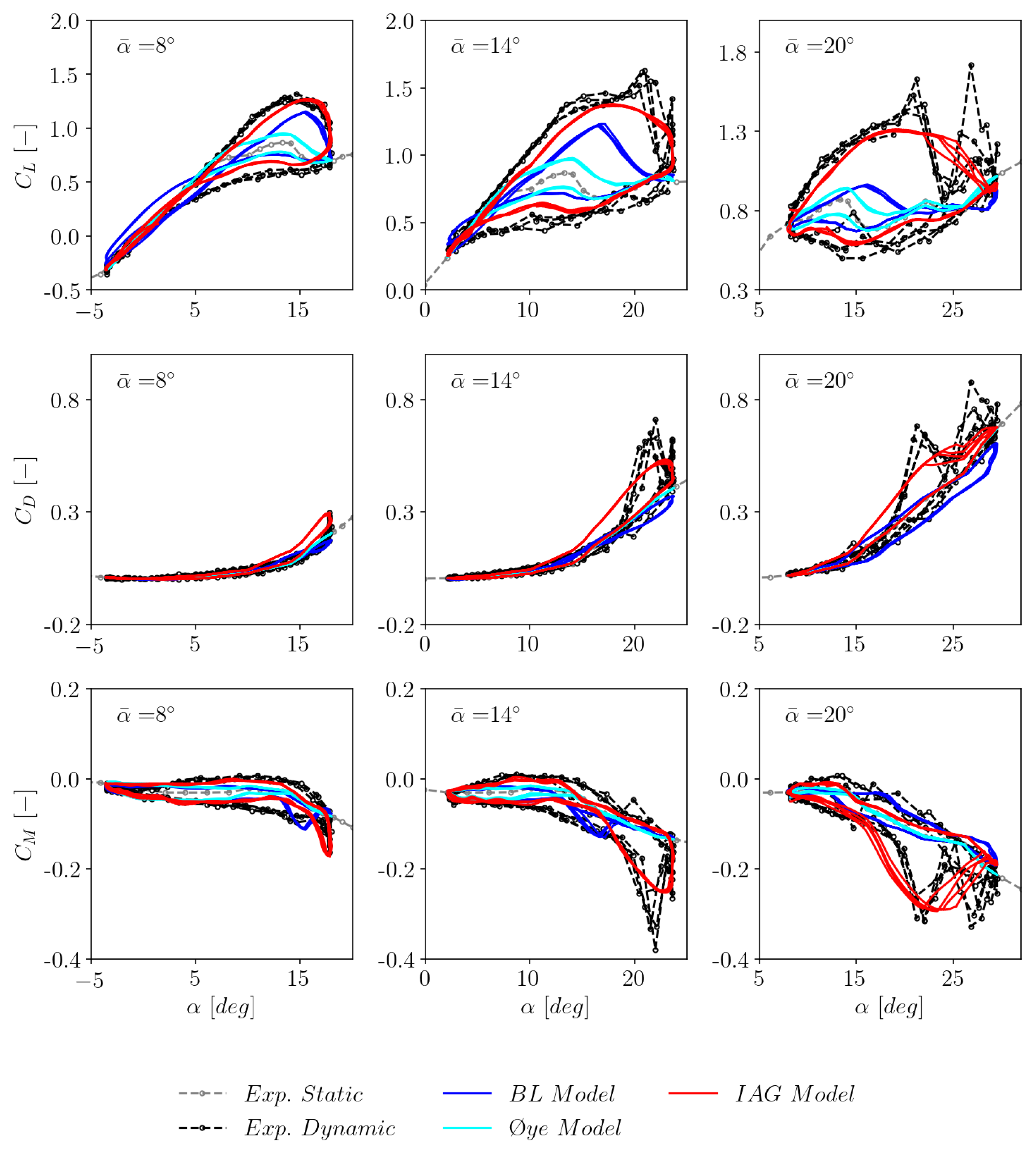
3.3. The effects of mean angle of attack
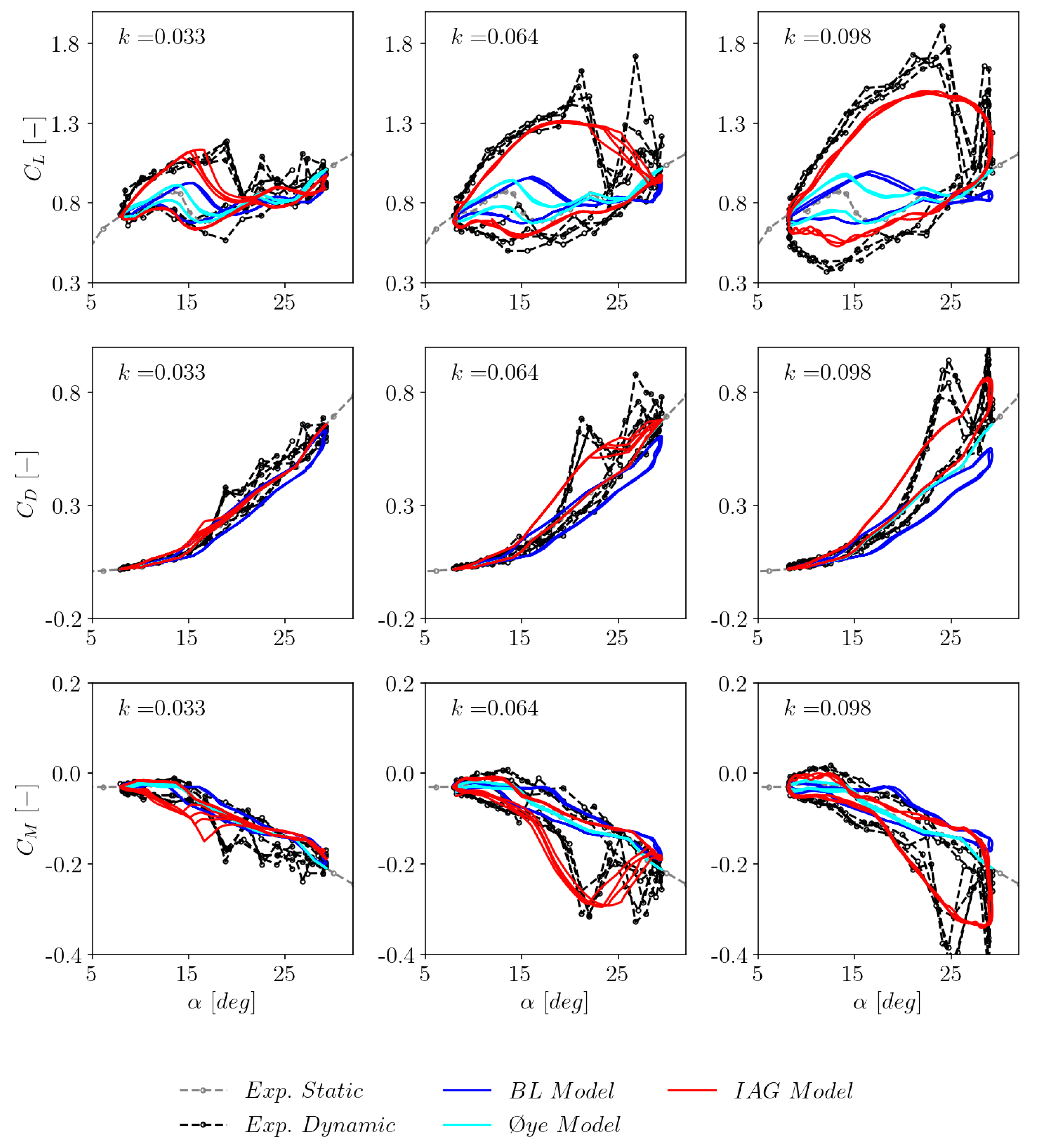
3.4. The effects of reduced frequency
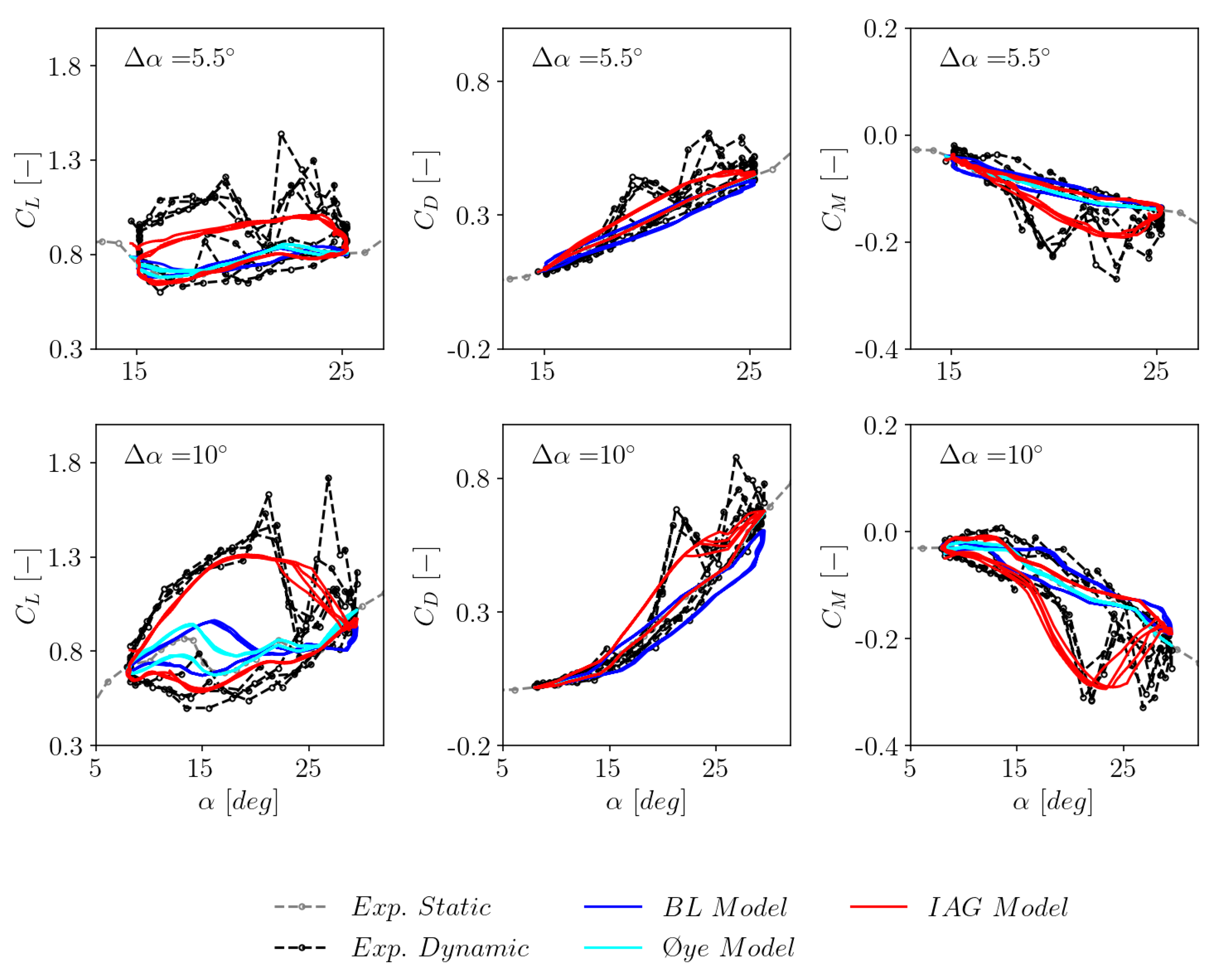
3.5. The effects of excitation amplitude
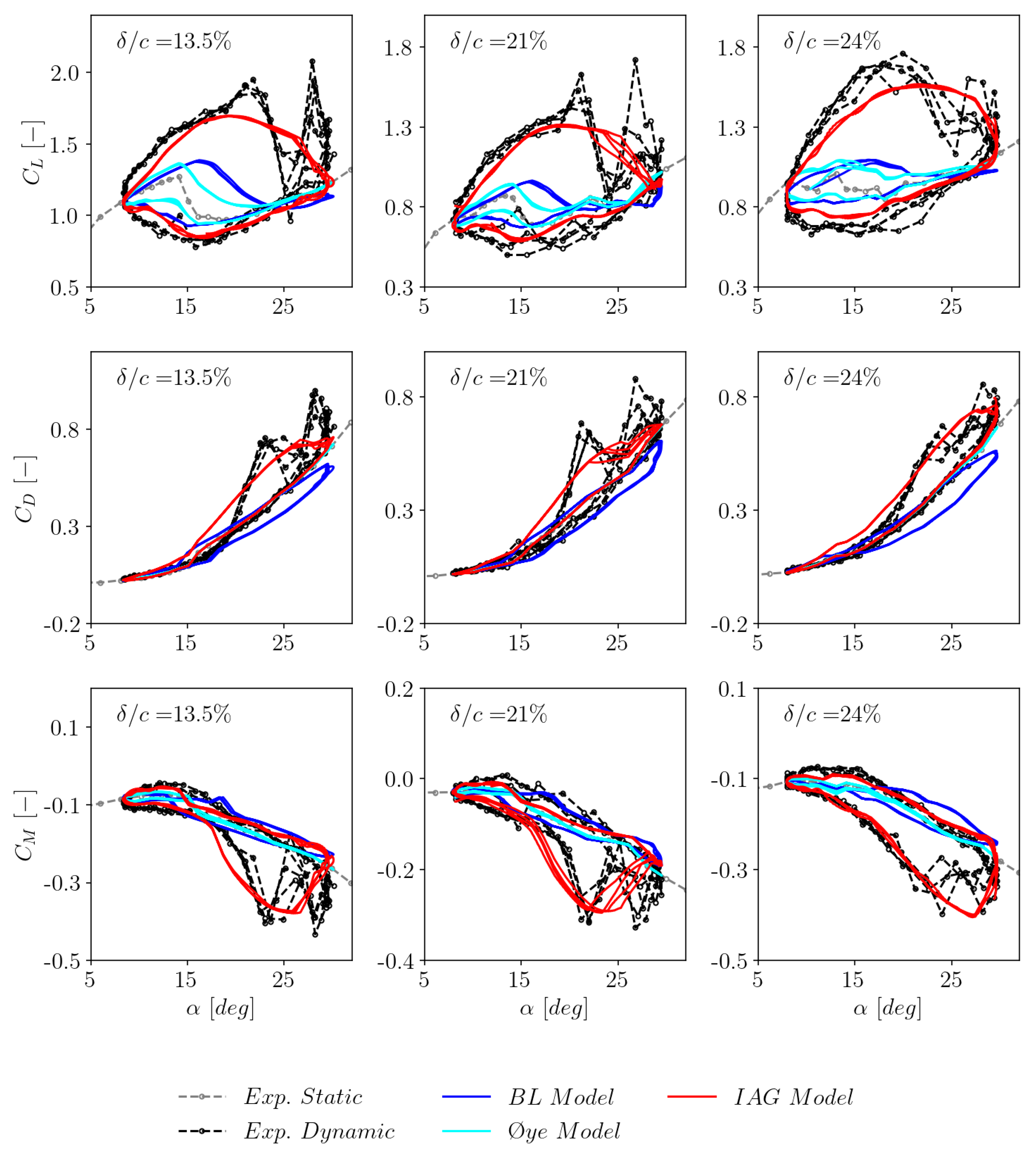
3.6. Sensitivity to airfoil thickness
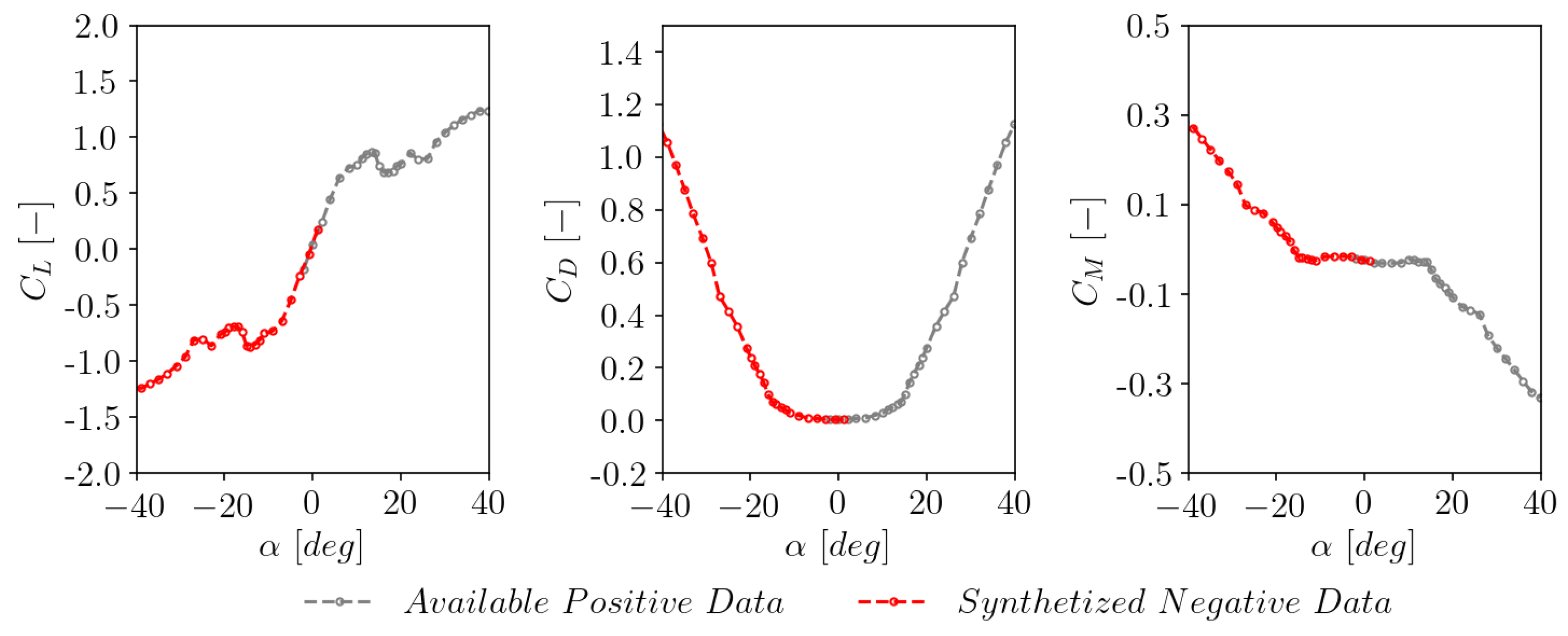
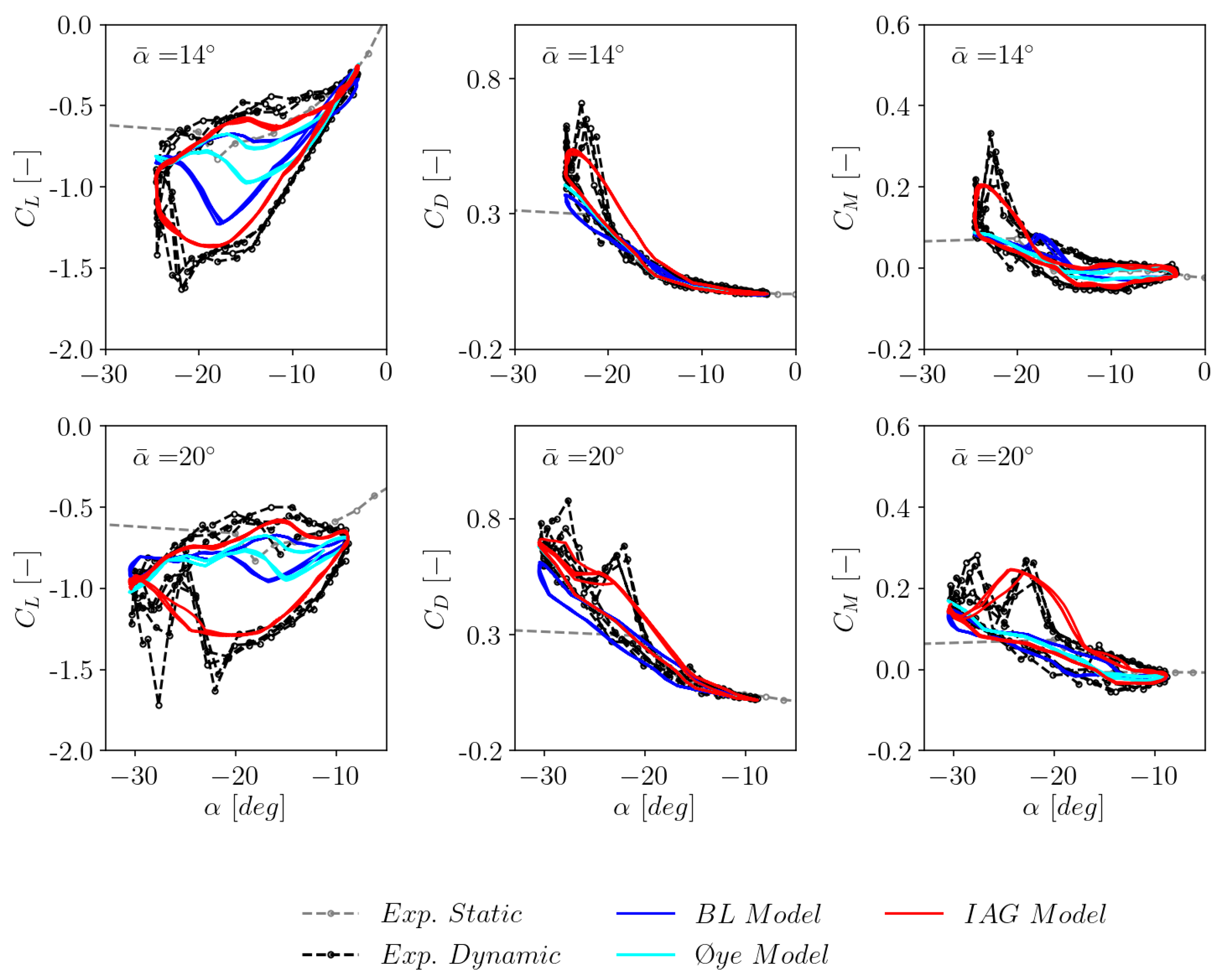
3.7. Model performance for negative stall
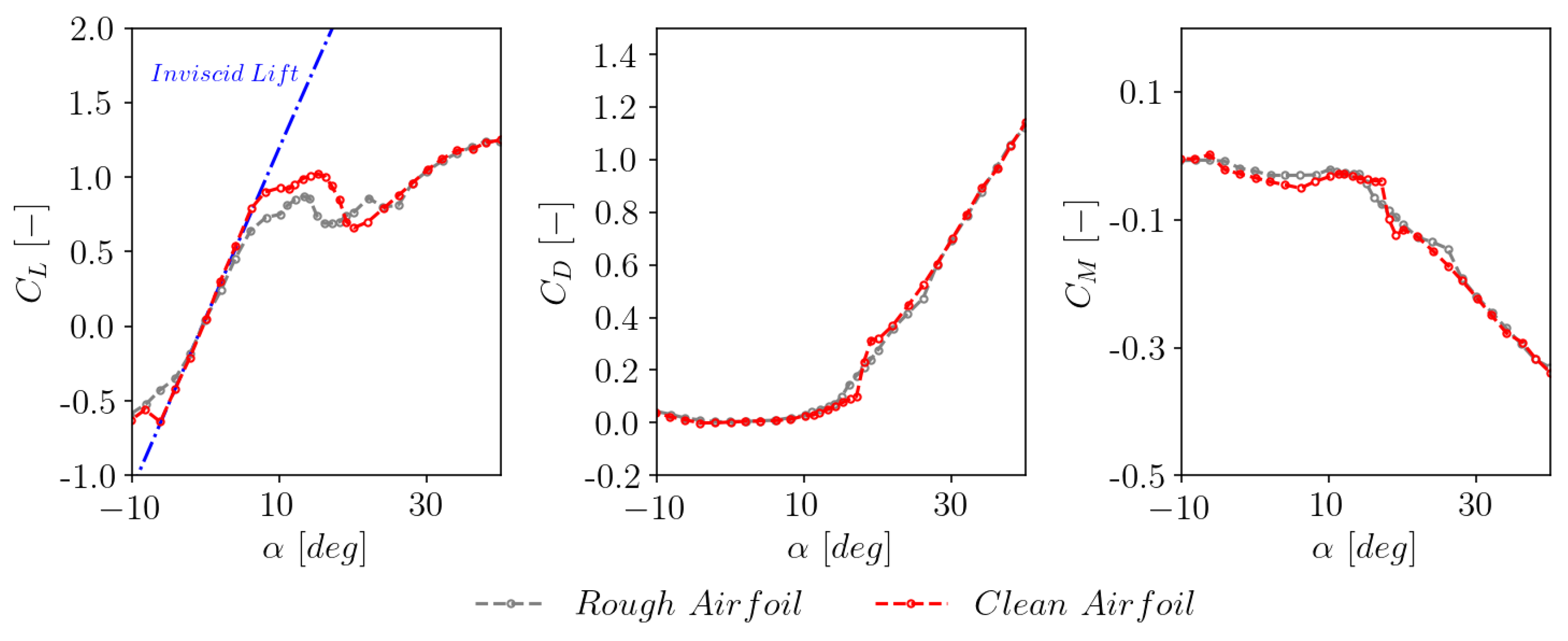
3.8. Sensitivity to airfoil surface roughness
3.9. Sensitivity to Reynolds number
4. Conclusions and Outlook
- The state-space representation of the IAG model has been successfully formulated.
- All the governing equations and assumptions are presented in a consistent manner to allow replication for future studies.
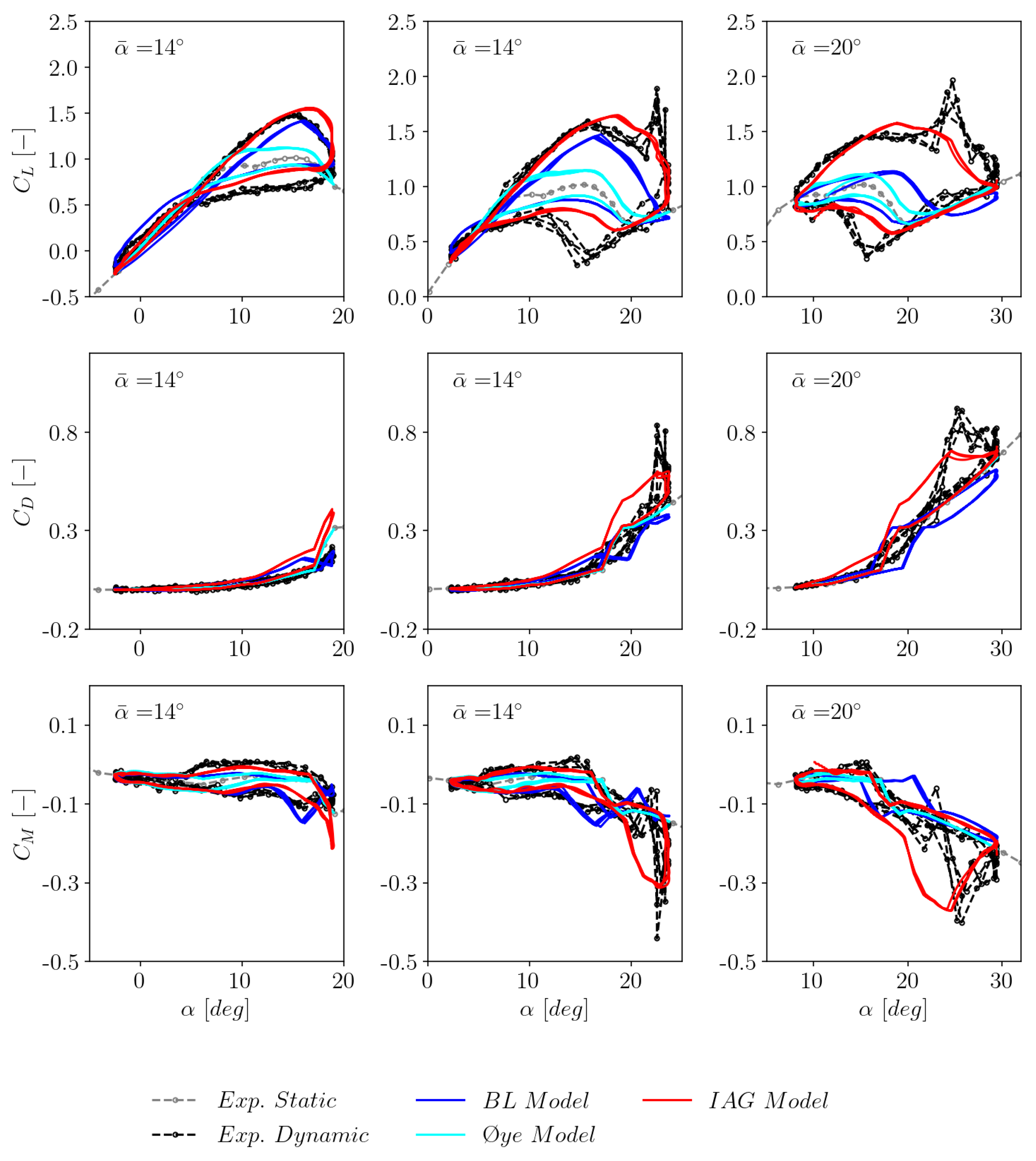
- The newly implemented IAG model clearly shows superior performance compared to the standard incompressible Beddoes-Leishman model and the Øye model in Bladed.
- The IAG model demonstrates a good accuracy against experimental data under various unsteady parameters, including the effects of mean angle of attack, reduced frequency and excitation amplitude.
- The IAG model results are able to be generalized to airfoils having different relative thicknesses.
- The performance of the IAG model is well validated for both clean airfoil and airfoil under the effects of surface roughness.
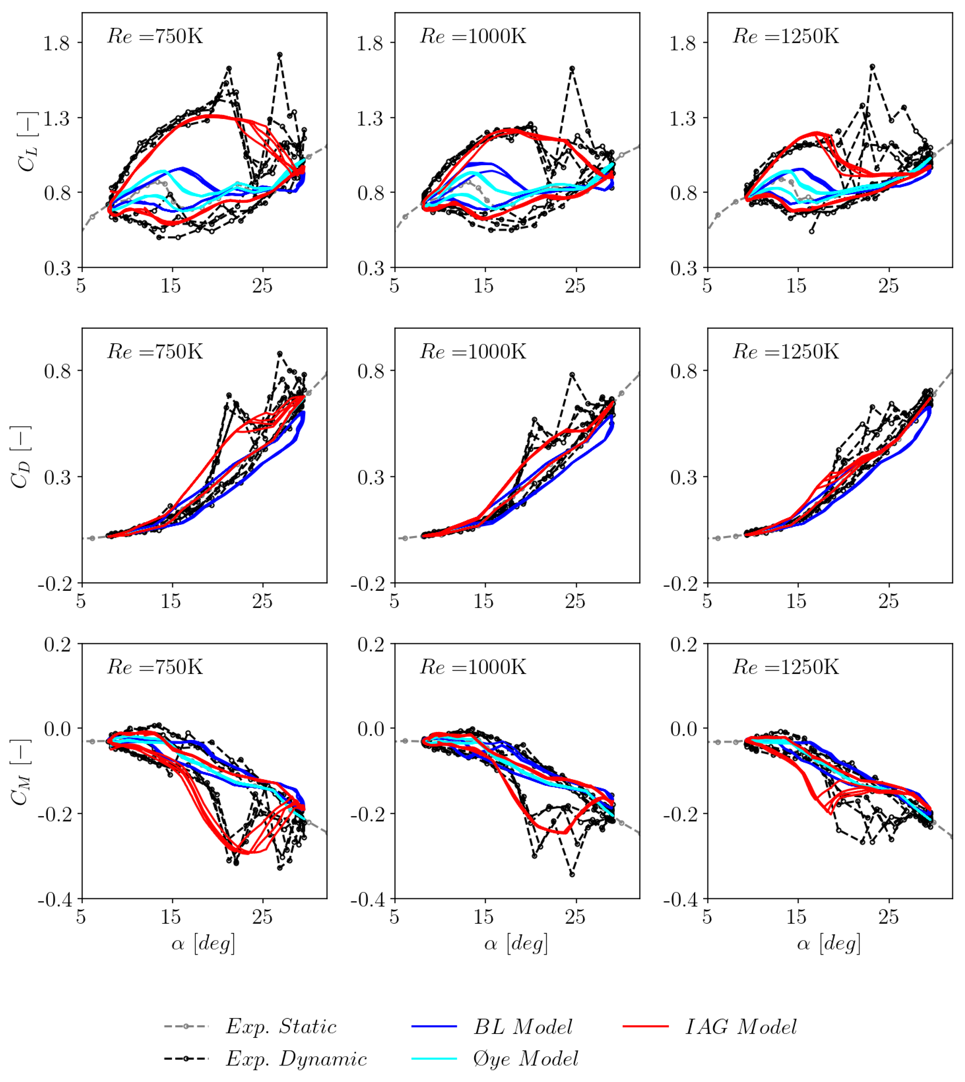
- The IAG model agrees well with the measurement data for three different values of the Reynolds number.
- The incompressible BL model prediction is deemed sufficient for small to moderate angle of attack cases.
Author Contributions
Funding
Institutional Review Board Statement
Informed Consent Statement
Data Availability Statement
Acknowledgments
Conflicts of Interest
References
- Martin, J.; Empey, R.; McCroskey, W.; Caradonna, F. An experimental analysis of dynamic stall on an oscillating airfoil. Journal of the American Helicopter Society 1974, 19, 26–32. [Google Scholar] [CrossRef]
- Carr, L.W.; McAlister, K.W.; McCroskey, W.J. Analysis of the development of dynamic stall based on oscillating airfoil experiments. Technical report, NASA TN D-8382, National Aeronautics and Space Administration, United States, 1977.
- McAlister, K.W.; Carr, L.W.; McCroskey, W.J. Dynamic stall experiments on the NACA 0012 airfoil. Technical report, NASA Technical Paper 1100, National Aeronautics and Space Administration, United States, 1978.
- Ramsay, R.; Hoffman, M.; Gregorek, G. Effects of grit roughness and pitch oscillations on the S801 airfoil. Technical report, National Renewable Energy Lab., Golden, CO (United States), 1996.
- Hoffman, M.; Ramsay, R.; Gregorek, G. Effects of grit roughness and pitch oscillations on the NACA 4415 airfoil. Technical report, National Renewable Energy Lab., Golden, CO (United States), 1996.
- Ramsay, R.; Hoffman, M.; Gregorek, G. Effects of grit roughness and pitch oscillations on the S809 airfoil. Technical report, National Renewable Energy Lab., Golden, CO (United States), 1995.
- Janiszewska, J.; Ramsay, R.; Hoffman, M.; Gregorek, G. Effects of grit roughness and pitch oscillations on the S814 airfoil. Technical report, National Renewable Energy Lab., Golden, CO (United States), 1996.
- Bangga, G.; Hutomo, G.; Wiranegara, R.; Sasongko, H. Numerical study on a single bladed vertical axis wind turbine under dynamic stall. Journal of Mechanical Science and Technology 2017, 31, 261–267. [Google Scholar] [CrossRef]
- Bangga, G. Numerical studies on dynamic stall characteristics of a wind turbine airfoil. Journal of Mechanical Science and Technology 2019, 33, 1257–1262. [Google Scholar] [CrossRef]
- Bangga, G.; Hutani, S.; Heramarwan, H. The Effects of Airfoil Thickness on Dynamic Stall Characteristics of High-Solidity Vertical Axis Wind Turbines. Advanced Theory and Simulations 2021, 4, 2000204. [Google Scholar] [CrossRef]
- Leishman, J.G.; Beddoes, T. A Semi-Empirical model for dynamic stall. Journal of the American Helicopter society 1989, 34, 3–17. [Google Scholar]
- Hansen, M.H.; Gaunaa, M.; Madsen, H.A. A Beddoes-Leishman type dynamic stall model in state-space and indicial formulations. Technical report, Risø-R-1354, Risø National Laboratory, Denmark, 2004.
- Bangga, G.; Lutz, T.; Arnold, M. An improved second-order dynamic stall model for wind turbine airfoils. Wind Energy Science 2020, 5, 1037–1058. [Google Scholar] [CrossRef]
- Larsen, J.W.; Nielsen, S.R.; Krenk, S. Dynamic stall model for wind turbine airfoils. Journal of Fluids and Structures 2007, 23, 959–982. [Google Scholar] [CrossRef]
- Gupta, S.; Leishman, J.G. Dynamic stall modelling of the S809 aerofoil and comparison with experiments. Wind Energy 2006, 9, 521–547. [Google Scholar] [CrossRef]
- Elgammi, M.; Sant, T. A Modified Beddoes–Leishman Model for Unsteady Aerodynamic Blade Load Computations on Wind Turbine Blades. Journal of Solar Energy Engineering 2016, 138, 051009. [Google Scholar] [CrossRef]
- Wang, Q.; Zhao, Q. Modification of Leishman–Beddoes model incorporating with a new trailing-edge vortex model. Proceedings of the Institution of Mechanical Engineers, Part G: Journal of Aerospace Engineering 2015, 229, 1606–1615. [Google Scholar] [CrossRef]
- Sheng, W.; Galbraith, R.M.; Coton, F. A new stall-onset criterion for low speed dynamic-stall. Journal of solar energy engineering 2006, 128, 461–471. [Google Scholar] [CrossRef]
- Galbraith, R. Return from Airfoil Stall During Ramp-Down Pitching Motions. Journal of Aircraft 2007, 44, 1856–1864. [Google Scholar]
- Sheng, W.; Galbraith, R.; Coton, F. A modified dynamic stall model for low Mach numbers. Journal of Solar Energy Engineering 2008, 130. [Google Scholar] [CrossRef]
- Øye, S. Dynamic stall simulated as time lag of separation. In Proceedings of the Proceedings of the 4th IEA Symposium on the Aerodynamics of Wind Turbines. Rome, Italy, 1991.
- Tran, C.; Petot, D. Semi-empirical model for the dynamic stall of airfoils in view of the application to the calculation of responses of a helicopter blade in forward flight. In Proceedings of the 6th European Rotorcraft Forum, 1980.
- Tarzanin, F. Prediction of control loads due to blade stall. Journal of the American Helicopter Society 1972, 17, 33–46. [Google Scholar] [CrossRef]
- Snel, H. Heuristic modelling of dynamic stall characteristic. In Proceedings of the Proceedings of the European Wind Energy Conference, 1997.
- Adema, N.; Kloosterman, M.; Schepers, G. Development of a Second Order Dynamic Stall Model. Wind Energy Science Discussions 2019, 2019, 1–18. [Google Scholar] [CrossRef]
- UK, D.S. Bladed Theory Manual 4.14; DNV Services UK, 2022.
- Beddoes, T. Practical computation of unsteady lift. In Proceedings of the 8th European Rotorcraft Forum, 1982.
- Leishman, J. Validation of approximate indicial aerodynamic functions for two-dimensional subsonic flow. Journal of Aircraft 1988, 25, 914–922. [Google Scholar] [CrossRef]
- Garbaruk, A.; Shur, M.; Strelets, M.; Travin, A. NACA0021 at 60 deg. incidence. Notes on Numerical Fluid Mechanics and Multidisiplinary Design 2009, 103, 127–139. [Google Scholar]
- Bangga, G. Comparison of blade element method and CFD simulations of a 10 MW wind turbine. Fluids 2018, 3, 73. [Google Scholar] [CrossRef]
- Bangga, G.; Lutz, T. Aerodynamic modeling of wind turbine loads exposed to turbulent inflow and validation with experimental data. Energy 2021, 223, 120076. [Google Scholar] [CrossRef]
| Model | ||||||||||||||
| Indicial IAG | 0.3 | 0.7 | 0.7 | 0.53 | 0.75 | 1.7 | 3.0 | 6.0 | 6.0 | 0.2 | 0.1 | 1.5 | 1.5 | 0.76 |
| State-Space IAG | 0.3 | 0.7 | 0.7 | 0.53 | 0.75 | 1.7 | 3.0 | 6.0 | 6.0 | 0.2 | N/A | N/A | N/A | N/A |
| Model | S801 | S809 | S814 | |
| Indicial IAG | 15.1° | 14.1° | 10° | |
| State-Space IAG | Automatic | Automatic | Automatic | Automatic |
Disclaimer/Publisher’s Note: The statements, opinions and data contained in all publications are solely those of the individual author(s) and contributor(s) and not of MDPI and/or the editor(s). MDPI and/or the editor(s) disclaim responsibility for any injury to people or property resulting from any ideas, methods, instructions or products referred to in the content. |
© 2023 by the authors. Licensee MDPI, Basel, Switzerland. This article is an open access article distributed under the terms and conditions of the Creative Commons Attribution (CC BY) license (http://creativecommons.org/licenses/by/4.0/).


