Submitted:
31 March 2023
Posted:
06 April 2023
You are already at the latest version
Abstract
Energy storage systems (ESSs) are the key elements to improve the operation of power systems. On the other hand, these elements challenge the power system planners. The difficulties arise as a result of the ESSs' economic and technological features. The cycle life of ESSs is a critical aspect that influences the choices made during expansion planning processes. In this manuscript, we have focused on a new model for the expansion planning of ESSs considering the impacts of technical properties, such as the cycle life and depth of discharge. For this purpose, the proposed model consists of the hourly operation planning of ESSs in the sample days of year. A new indicator is proposed to determine the daily charging/discharging cycles of ESSs. Numerical results show the ability of the proposed model to determine the optimal technology and capacity of ESSs.
Keywords:
Cycle life
; Depth of discharge
; Energy storage system
; Expansion Planning
1. Introduction
Energy storage systems (ESSs) play
a significant role in distributed power systems and utility power systems [1,2]. But, the high investment cost is one of the
main challenges of ESSs. As a result, expanding ESSs while taking their
technical and economic aspects into account is a primary research area for
power system experts [3].
In recent years, significant
research was conducted on the expansion planning of the ESSs [4,5]. The main difference among these studies is
how to model ESSs expansion planning problem and how to formulate the problem.
In the objective function is considered to minimize the hourly social cost and
maximize the penetration of wind power resources [6].
The minimizing of total system costs is considered in as the objective function
[7]. But, in this manuscript, the possibility
of price arbitrage and profitability resulting from the voltage and frequency
control is applied in the model.
Along with the optimal expansion
planning of ESSs, the wind production capacity was optimized. In the proposed
model, ESS was used to reduce the need to invest in transmission systems to
increase the penetration of wind generation resources [8].
A multi-objective optimization
problem, which minimizes wind energy curtailment and total social cost and
maximizes profit from the price arbitrage, is proposed in the ESS expansion
problem [9].
A new model for expansion planning
of distributed ESSs is presented in [10].
Instead of using a centralized storage system, several distributed storage systems
are used in the proposed method. In the model presented in this manuscript, a
three-level planning method is used to determine the location and capacity of
the ESS. In the first stage, the optimal location of ESS and its power capacity
is separately determined for each day of year. The second stage determines
ESS's power and energy capacity at the sites selected in the previous phase.
The third phase determines how to employ ESS to alleviate transmission line
congestion based on the location and capacity of ESS indicated in the preceding
stages. Kargarian et al. divided the ESS expansion planning problem into two
different time horizons, hourly and inter-hourly [11].
In the inter-hour time horizon, the algorithm determines the optimal energy
capacity of the ESS to provide the adequate ramping capability. At hourly
intervals, the optimal power capacity of ESS is determined to have sufficient
production capacity to supply the load.
A new model for the coordinated
expansion planning of transmission systems and ESSs, taking into account
transmission switching, is proposed in [12].
A three-level model for the
simultaneous optimization of the transmission lines and ESSs are presented [13]. In this model, the optimal location and
capacity of the ESS are determined. The centralized development of the
transmission lines was carried out. The suggested model's high level optimizes
the return on investment for investors. The model's intermediate level
optimizes the major choices associated with ESS expansion planning. The
low-level simulation models market settlement.
In the coordinated investment
planning of transmission lines and ESSs is presented from the perspective of a
central planner. The proposed model aims to achieve the effective and
coordinated development of transmission lines and ESSs to minimize the cost of
investment with significant penetration of renewable energy sources [14].
A bi-level model is presented for
expansion planning of the electrical energy resources considering the ESSs [15]. The ESSs are modeled in the upper level, and
Social welfare is considered in the lower level.
In a two-stage robust
optimization-based model is proposed for the expansion planning of active
distribution systems coupled with urban transportation networks considering
ESSs. The uncertainty of renewable energy, load, and traffic demand in the
proposed model are jointly considered [16].
A new stochastic model is proposed
to study the expansion planning problem of ESSs in micro grids, which contain
renewable resources and responsive loads. The optimization problem is prepared
as two-stage stochastic programming [17].
In a mixed-integer conic
programming model (MICP) and a hybrid solution approach based on classical and
heuristic optimization techniques, namely mat heuristics to handle long-term
distribution systems expansion planning problems is presented for sizing and
allocation of dispatch able/renewable distributed generation (DG) and energy
storage devices [18]. A bi-level formulation
for the generation and transmission coordination problem considering the ESS
expansion planning is presented in [19].
A new stochastic framework to deal
with the expansion planning of large distribution networks in a smart grid
context with high penetration of distributed renewable energy sources and ESSs
considering the seasonal impact is proposed in [20].
In a reliability-constrained
optimal ESS sizing for a micro grid is proposed [21].
The model presented for ESS expansion planning is based on cost minimization in
the islanded operating mode of micro grid and profit maximization when it is
operated in the grid-connected mode [22].
In pollutant emission costs are
considered in the objective function of ESS expansion planning model [23].
Joint optimization of hybrid ESS
and generation capacity with renewable energy resources is carried out in [24]. Optimal sizing and control strategy of the
isolated grid with wind power and ESS considering the compensation costs of the
curtailed wind power and load shedding is presented [25].
The proposed ESS sizing method is based on the discrete Fourier transform [26].
A simultaneous capacity
optimization method for distributed generators (DGs) and ESSs considering the
energy serving and annual losses costs is presented proposes a novel model for
planning ESS expansions based on the dynamic investment strategy [27,28]. Presents a frequency-based strategy for
expanding ESSs in the power system using the Fourier transform [29]. A new model for Optimal ESS expansion planning
and load shedding to improve distribution system reliability is proposed [30].
This manuscript presents a new
model for expansion planning of the ESSs. The proposed model is formulated as a
probabilistic optimization problem from the perspective of system operator. The
main novelty of proposed model compared to above reviewed articles is modeling
the cycling properties of the ESSs in the expansion planning problem. The depth
of discharge effect on the cycle life of the ESSs is formulated. In a number of
articles, only the life cycle cost was examined, and exact modeling of cycle
life in the expansion planning of the ESSs has not been addressed.
Cycle life is defined as the maximum number of
ESS charge and discharge cycles during the ESS life span.
Indeed, the novelties of presented
model are as follows:
- - Proposing a new indicator to determine the daily charging/discharging cycles of the ESSs.
- - Modeling the cycle life in the expansion planning formulation.
- - Considering the depth of discharge of ESSs in the expansion planning model.
This research is organized as
follows. Section 2 introduces the
proposed model for the ESS expansion planning. This section presents the
formulation of the proposed model. The simulation results are described in
section 3. Finally, section 4 provides the concluding remarks.
2. Model Description
2.1. ESS expansion planning
In this study, it is supposed that
ESS expansion planning is carried out from the system planner's point of view.
To model the limitations of charging/discharging cycles of ESSs within ESS expansion
planning problem, the operation problem is solved. The proposed operation
problem deals with the participation of production units and ESSs in the
day-ahead market. In the presented model, in addition to determining the
optimal capacity of the ESSs, the optimal technology of the ESSs will also be
determined.
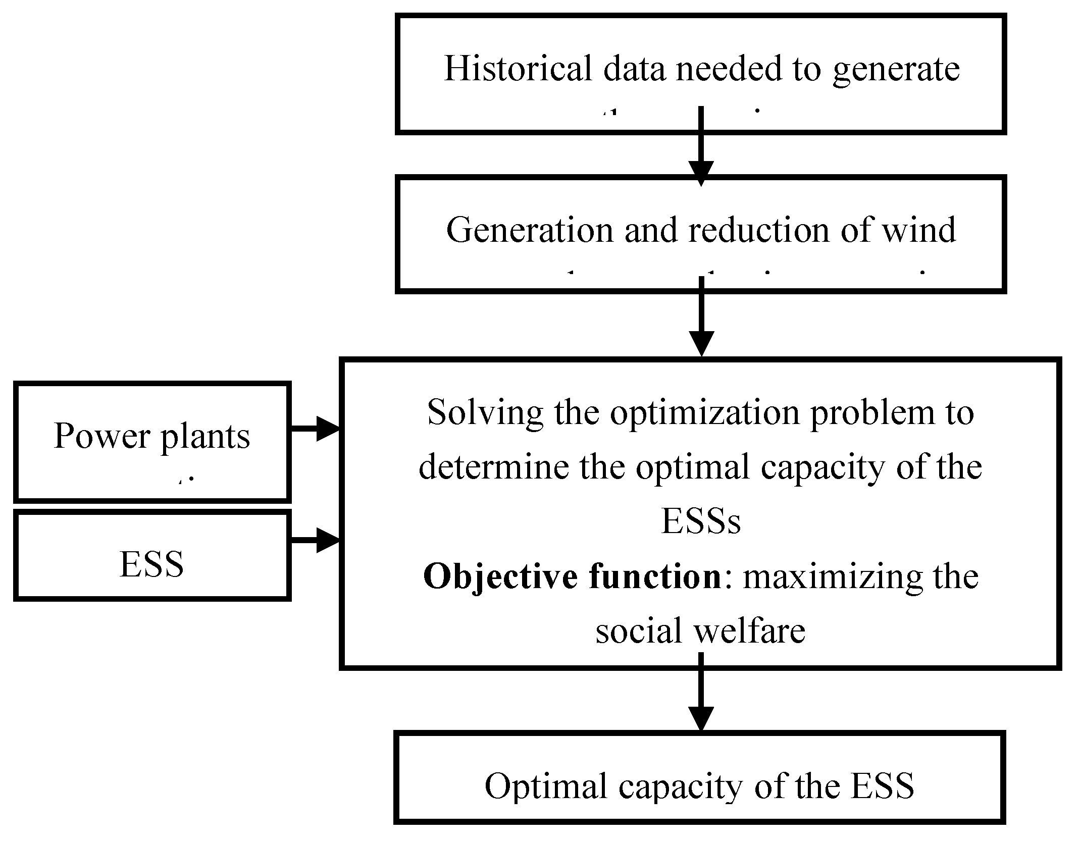
The general structure of the
proposed model is shown in Figure 1. In
this model, the operation planning for the hours of the annual sample days is
carried out inside the expansion planning problem. System operation during this
target year is therefore modeled using representative days, each of which is
given a weight proportional to the probability of occurrence of a similar day.
At first, the historical data of wind power plants are used to generate the
probabilistic scenarios of wind power generation. After generating
probabilistic scenarios, the scenarios are reduced and considered inputs in ESS
expansion planning problem. The technical and economic properties of power
plants and ESSs are the other inputs of the ESS expansion planning problem.
In the following, at first, the
general formulation of problem without considering the limitations of
charging/discharging cycles is presented. Then, the necessary relationships for
modeling the cycle life of the ESSs are presented.
Figure 1.
Block diagram of the proposed model.
Social welfare is defined as the
difference between producers' profits and consumers' costs. In the proposed
model, the price elasticity of the load is neglected. Therefore, minimization
of the total operating costs of the system and investment costs of the ESSs are
considered the objective function of optimization problem. The objective
function of the proposed model is as follows:
The first and second terms refer
to the traditional power plants' yearly operating and maintenance costs,
respectively. The third term is used to predict the yearly running costs of
wind generating installations. The fourth and fifth terms, respectively, define
the yearly leakage cost and maintenance cost of wind power facilities. The
sixth term is the annual cost of investing in ESSs. The annual operating cost
and maintenance cost of ESSs are calculated in the seventh and eighth terms,
respectively. The proposed formulation makes it possible to simultaneously
determine the optimal technology and capacity of the ESSs. In fact, terms six,
seven and eight terms can be calculated for different ESS technologies to
determine the optimal technology. The ninth term determines the rewards paid to
the flexible loads. The annual operating cost of the conventional power plants
is determined using the following equation.
The annual operating cost consists
of the cost of power supply and the cost of turning on and off the power
plants.
The annual operating cost and
spillage cost of the wind power plants are determined using (3) and (4),
respectively.
The investment cost and
operation cost of ESSs are calculated in (5) and (6), respectively.
The constraints of problem are
presented below [31-32]. Minimum and maximum production of
conventional power plants:
Ramping up capability of
conventional power plants:
Ramping down capability of
conventional power plants:
Startup cost of the conventional
power plants:
Shut down cost of conventional
power plants:
Minimum up time of conventional
power plants:
Minimum down time of conventional
power plants:
Dispatched production of wind
power plants:
Spillage of the wind power plants:
Power balance of ESSs:
State of charge of ESSs:
Energy limitation of ESSs:
Power limitation of ESSs:
Power constraint for installation
of ESS technologies:
Energy constraint for installation
of ESS technologies:
Equality of supply and demand in
energy market:
(22)
Constraint of the flexible loads:
10 min spinning reserve constraint
of system:
Reserve constraint of system:
Capability of the conventional
power plants for spinning reserve provision:
Capability of the ESSs for
spinning reserve provision:
2.2. Modeling the cycle life of the ESS:
One of the ESSs' technical
features is their restricted number of charging/discharging cycles.
In fact, in addition to having a
lifetime limit in terms of years, the ESS also has a limit on the number of
charge and discharge cycles. This means that during the operation period of the
ESS, even if the ESS is charged and discharged as much as the cycle life before
the end of the useful life, it must be replaced.
In this manuscript, a new index is
proposed to evaluate the cycle life of the ESS. In the proposed method to
determine this index, the number of charge and discharge cycles is calculated
for different operating scenarios every day. For this purpose, to represent the
constraints of charging/discharging cycles, the cycle life of ESSs is estimated
using the following equation:
According to the above
relationship to determine the cycle life, the total energy charged and
discharged in each scenario is calculated during the day. With a good
approximation, the number of charge and discharge cycles can be determined by
dividing the obtained energy by 2 times the energy storage capacity.
The cycle life of ESS is
restricted using the following equation.
Based on the above relationship,
the number of charge and discharge cycles on the days of operation of the ESS
in each year should not exceed the allowed charge and discharge capacity per
year.
Another important parameter
affecting the performance of the ESSs is the depth of discharge, which has not
usually been considered in the expansion planning studies of the ESSs. But
studies show that the depth of discharge has a significant effect on the number
of allowed cycles of the ESSs. So not taking this into account takes the expansion
planning outputs away from what actually happens in operation. For this
purpose, in this article, the effect of the depth of discharge on the lifetime
of the ESS is modeled, and to model this phenomenon in the planning problem,
constraints have been added to the proposed formulation.
By examining the technical
characteristics of the ESSs, it can be seen that the depth of discharge of the
ESSs is inversely related to the cycle life.
In the proposed model in this
manuscript, to model the effect of depth of discharge on the cycle life, the
curve of the maximum number of cycle life is modeled as the piecewise linear
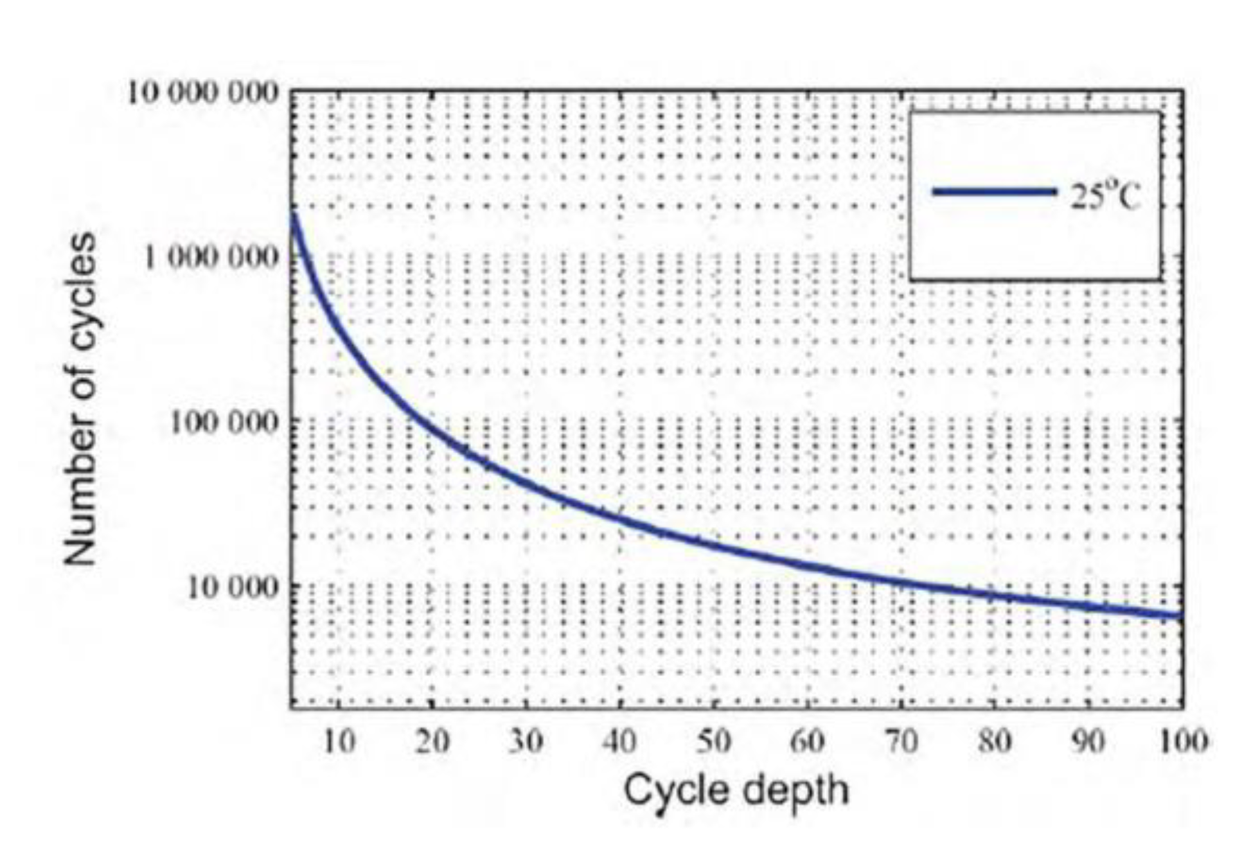
approximation according to Figure 2. The
approximation is formulated as follows.
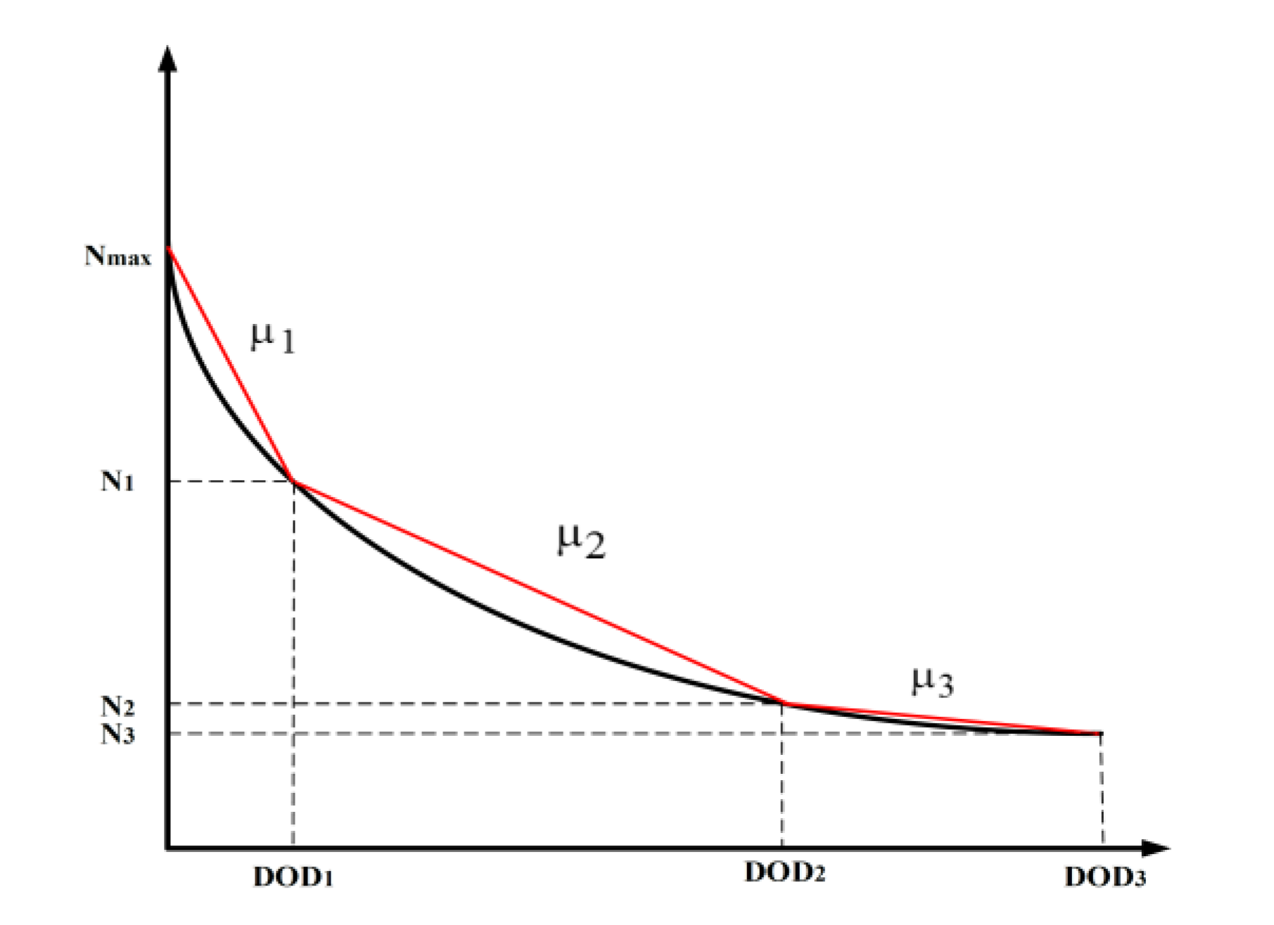
Figure 2.
Piecewise linear approximation of cycle life curve of the ESSs.
Depth of discharge is restricted
as follows.
If depth of discharge is
considered as a variable, then (18) will be nonlinear. To linearize this
relationship, the product of two variables,
, is defined as a new variable
using the following equation:
Thus (18), will be as follows:
And the following constraints are
added to the formulation.
3. Results
To illustrate the capability of
the proposed model, the structure presented in Figure
3, is considered the case study. The system consists of three
conventional power plants with properties displayed in Table 1. A wind power plant introduced in Table 2 is assumed in the case study. Two ESSs
with properties presented in Table 3 are
evaluated for allocating in the system.
In the proposed model, the sample
daily demands of the year are considered the representative of each season.
Demands are divided into two categories: fixed and flexible. The seasonal
sample fixed demands are shown in Figure 4.
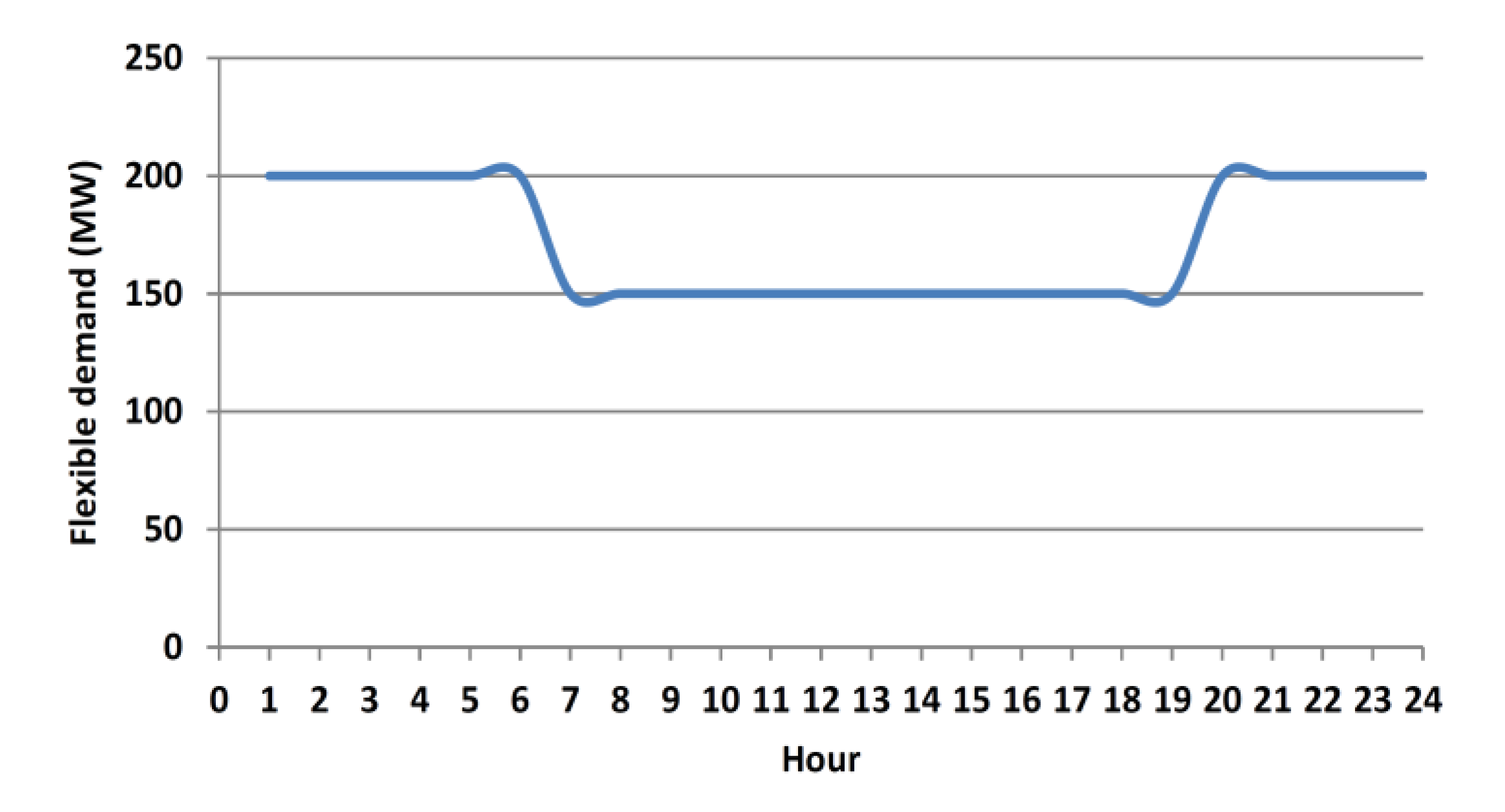
The daily flexible demands are depicted in Figure
5.
In the presented method, the
stochastic nature of wind power plant production is modeled by the scenario
based simulation. For this purpose, the ARIMA model of the wind power plant
production is determined. Then, 10000 scenarios are generated using the Monte
Carlo simulation. The 10000 scenarios are then reduced to 10 scenarios using
the fast forward scenario reduction technique [33].
The MATLAB software is employed to determine the ARIMA model degrees and
coefficients, and scenario generation and reduction. The interruption cost for
flexible demand is considered 100 $/MW, and the threshold of spinning and
non-spinning reserves are defined 100 and 200 MW, respectively.
Figure 3.
Structure of case study.
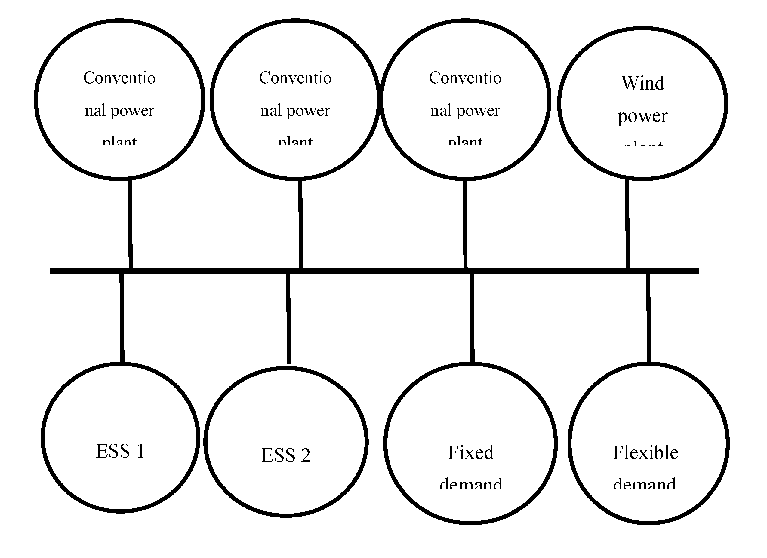

Table 1.
Conventional power plants properties.
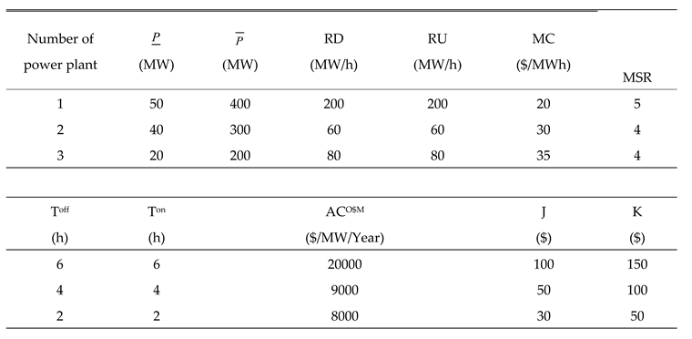
Table 2.
Wind power plant properties.
Table 3.
ESSs properties.
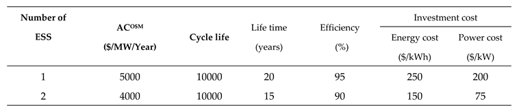
Figure 4.
Daily fixed demand.
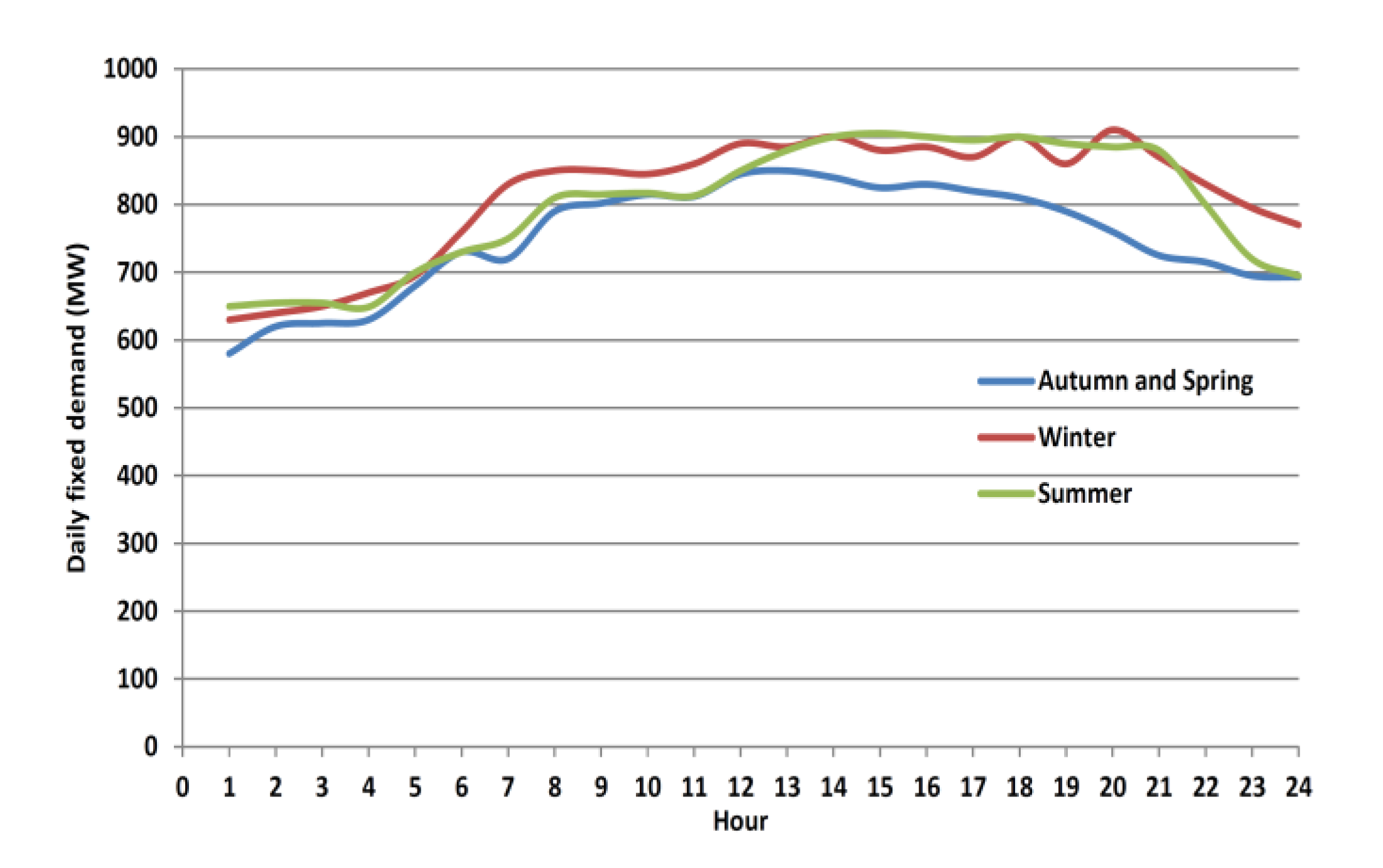
Figure 5.
Daily flexible demand.
The following four simulations
were performed to investigate the impacts of the ESS specifications on the expansion
planning results.
Simulation 1:
- - Depth of discharge is considered fixed and equal to 0.9.
- - The ESSs presented in Table 3 are considered in the studies.
Simulation 2:
- - Depth of discharge is considered fixed and equal to 0.9.
- - The efficiency of the second ESS in Table 3 is considered equal to % 80.
Simulation 3:
- - Depth of discharge is considered fixed and equal to 1.
- - The efficiency of the second ESS in Table 3 is considered equal to % 80.
Simulation 4:
Figure 6.
Cycle life curve.
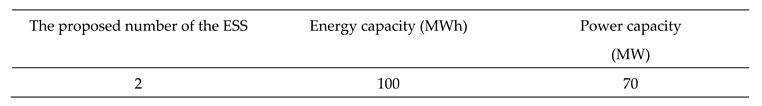
Simulation 1: The results of the
ESSs expansion planning for simulation 1 are presented in Table 4. In this case, only the second ESS is
proposed for development due to the lower cost. The simulation results show
that in this case, the demand interruption and the spillage of wind output will
be zero. The number of charging/discharging cycles according to the equation
defined in Equation (32) will be equal to 1.225. If the ESS is operated in all
days of the year, annual cycles are about 447 cycles. Thus, during the life of
this ESS (15 years), the number of required cycles will be about 6700 cycles.
Therefore, there will be no challenge regarding the limitation of the
charging/discharging cycles. On the other hand, using an ESS with the same
specifications as the second ESS, but with fewer charging/discharging cycles,
will be a good option in terms of the lower possible investment cost.
Table 4.
ESS expansion planning results is simulation 1.
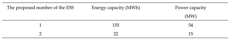
Simulation 2: In this case, the
efficiency of the second ESS is considered to be 80%. The output of the
proposed model is shown in Table 5. As
can be seen, in this case, ESS expansion for both ESSs is recommended. Because
the first ESS is more efficient despite the higher investment cost. The
simulations reveal that in this situation, the first and second ESSs have the
same number of charging/discharging cycles (1.1 and 0.9, respectively). Thus,
for the first and second ESSs, the total number of charging/discharging cycles
needed is 8030 and 4927 cycles, respectively.
Table 5.
ESS expansion planning results is simulation 2.
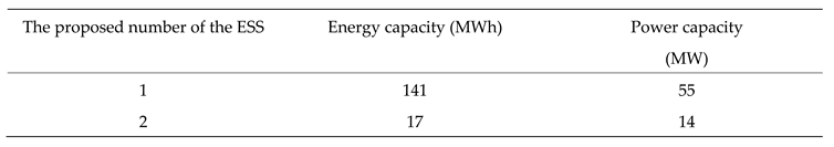
Simulation 3: In this case, all
assumptions are considered similar to the second simulation, but the depth of discharge
is assumed to be 1. It means that the full capacity of the ESSs is used. Table 6 presents the simulation results in this
case. As can be seen in this case, the capacities of ESSs are reduced. In this
case, the numbers of cycles required per day for the first and second ESSs will
be equal to 1.24 and 1.04, respectively. Therefore, the numbers of cycles
required during the life of the first and second ESSs are equal to 9052 and
5694 cycles, respectively.
Table 6.
ESS expansion planning results is simulation 3.
Simulation 4: In this case, the
goal is to determine the optimal depth of discharge of the ESSs based on the
equations of section 2.2. The curve presented in Figure 6, is considered as the discharge
depth/number of cycles curve for ESSs. The simulation results show that in this
case the proposed depth of discharge is equal to 100%. This is because in this
case, even with a discharge depth of 100%, the required number of
charging/discharging cycles will be less than the limit of charging/discharging
cycles. This indicates the correct operation of the proposed model.
If the relation Nmax=
-5000*DOD+10000 is considered for modeling the discharge depth/number of cycles
curve, the proposed depth of discharge will be %62.3. Because with 100%
discharge depth, the maximum charging/discharging cycles will be 5000, which
does not meet the required number of cycles during the ESS life.
By comparing the first and second simulations, it can be concluded that the change in ESS's efficiency has a significant effect on the composition of the developed ESSs. Comparing the second and third simulations shows that with a 10% increase in depth of discharge, the energy capacity of the first and second ESSs decreased by 10 and 22%, respectively. On the other hand, the required power capacity is slightly reduced. The results of the fourth simulation also show that optimal optimization of discharge depth can lead to more optimal decisions for ESSs development.
4. Conclusion
In this research, a model is presented for expansion planning of ESSs considering the cycle life. This model determines the optimal technology and capacity of the ESSs. Simulations were performed for different modes, and ESS expansion planning results are presented. In these studies, the impact of changing the efficiency of ESSs and the depth of discharges was studied. In each case, the number of daily charging/discharging cycles and the minimum number of charging/discharging cycles required during the life of ESSs are determined. Studies were performed for two modes of the constant discharge depth and linear modeling of the discharge depth.
The simulation results show that a reduction in the ESS efficiency reduces the energy capacity of the ESS. Efficiency significantly affects the number of daily charging/discharging cycles. The degree of impact also depends on the specifications of other ESSs. The results show that a 10% increase in the ESS depth of the discharge reduces the ESS energy capacity required by about 20%. Furthermore, the number of daily charging/discharge cycles increases by about 14%, which indicates an increase in ESS participation in energy supply.
Data Availability Statement
All data generated or analyzed during this study are included in this article.
Conflicts of Interest
The authors certify they have NO affiliations with or involvement in any organization or entity with any financial interest.
References
- Wen, S.; Lan, H.; Fu, Q.; Yu, D.C.; Zhang, L. Economic Allocation for Energy Storage System Considering Wind Power Distribution. IEEE Trans. Power Syst. 2014, 30, 644–652. [Google Scholar] [CrossRef]
- Oh, S.; Kong, J.; Yang, Y.; Jung, J.; Lee, C.-H. A multi-use framework of energy storage systems using reinforcement learning for both price-based and incentive-based demand response programs. Int. J. Electr. Power Energy Syst. 2023, 144. [Google Scholar] [CrossRef]
- Hessami, M.A.; Bowly, D. R. Economic Feasibility and Optimization of an Energy Storage System for Portland Wind Farm (Victoria, ustralia). Appl. Energ. 2011, 88, 2755–2763. [Google Scholar] [CrossRef]
- Yi, J.H.; Cherkaoui, R.; Paolone, M.; Shchetinin, D.; Knezovic, K. Expansion planning of active distribution networks achieving their dispatch ability via energy storage systems. Appl. Energ. 2022, 326, 119942. [Google Scholar] [CrossRef]
- Bodong, S.; Wiseong, J.; Chengmeng, L.; Khakichi, A. Economic management and planning based on a probabilistic model in a multi-energy market in the presence of renewable energy sources with a demand-side management program. Energy 2023, 269. [Google Scholar] [CrossRef]
- Ghofrani, M.; Arabali, A.; Etezadi-Amoli, M.; Fadali, M.S. A Framework for Optimal Placement of Energy Storage Units Within a Power System With High Wind Penetration. IEEE Trans. Sustain. Energy 2013, 4, 434–442. [Google Scholar] [CrossRef]
- Zhang, N.; Kang, C.; Kirschen, D.S.; Xia, Q.; Xi, W.; Huang, J.; Zhang, Q. Planning Pumped Storage Capacity for Wind Power Integration. IEEE Trans. Sustain. Energy 2012, 4, 393–401. [Google Scholar] [CrossRef]
- Fallahi, F.; Nick, M.; Riahy, G.H.; Hosseinian, S.H.; Doroudi, A. The value of energy storage in optimal non-firm wind capacity connection to power systems. Renew. Energy 2014, 64, 34–42. [Google Scholar] [CrossRef]
- Hozouri, M.A.; Abbaspour, A.; Fotuhi-Firuzabad, M.; Moeini-Aghtaie, M. On the Use of Pumped Storage for Wind Energy Maximization in Transmission-Constrained Power Systems. IEEE Trans. Power Syst. 2015, 30, 1017–1025. [Google Scholar] [CrossRef]
- Pandzic, H.; Wang, Y.; Qiu, T.; Dvorkin, Y.; Kirschen, D.S. Near-Optimal Method for Siting and Sizing of Distributed Storage in a Transmission Network. IEEE Trans. Power Syst. 2014, 30, 2288–2300. [Google Scholar] [CrossRef]
- Kargarian, A.; Hug, G. Optimal sizing of energy storage systems: a combination of hourly and intra-hour time perspectives. IET Gener. Transm. Distrib. 2016, 10, 594–600. [Google Scholar] [CrossRef]
- Dehghan, S.; Amjady, N. Robust Transmission and Energy Storage Expansion Planning in Wind Farm-Integrated Power Systems Considering Transmission Switching. IEEE Trans. Sustain. Energy 2016, 7, 765–774. [Google Scholar] [CrossRef]
- Dvorkin, Y.; Fernandez-Blanco, R.; Wang, Y.; Xu, B.; Kirschen, D.S.; Pandzic, H.; Watson, J.-P.; Silva-Monroy, C.A. Co-Planning of Investments in Transmission and Merchant Energy Storage. IEEE Trans. Power Syst. 2017, 33, 245–256. [Google Scholar] [CrossRef]
- Zhang, X.; Conejo, A.J. Coordinated Investment in Transmission and Storage Systems Representing Long- and Short-Term Uncertainty. IEEE Trans. Power Syst. 2018, 33, 7143–7151. [Google Scholar] [CrossRef]
- Rafiei, S.; Mohammadi Ivatlo, A.B. Bi-level model for generation expansion planning with contract pricing of renewable energy in the presence of energy storage. IET Renew Power Generat. 2019, 13, 1544–1553. [Google Scholar] [CrossRef]
- Xie, S.; Hu, Z.; Wang, J. Two-stage robust optimization for expansion planning of active distribution systems coupled with urban transportation networks. Appl. Energy 2020, 261. [Google Scholar] [CrossRef]
- BiazarGhadikolaei, M.; Shahabi, M.; Barforoushi, T. Expansion planning of energy storages in microgrid under uncertainties and demand response. Int. Trans. Electr. Energy Syst. 2019, 29. [Google Scholar] [CrossRef]
- Home-Ortiz, J.M.; Pourakbari-Kasmaei, M.; Lehtonen, M.; Mantovani, J.R.S. A Mixed Integer Conic Model for Distribution Expansion Planning: Matheuristic Approach. IEEE Trans. Smart Grid 2020, 11, 3932–3943. [Google Scholar] [CrossRef]
- Gonzalez-RomeroSonja, I.; Wogrin, S.; Gomes, T. Proactive transmission expansion planning with storage considerations. Energ. Strat. Revi. 2019, 24, 154–165. [Google Scholar] [CrossRef]
- Gonzalez-RomeroSonja, I.; Wogrin, S.; Gomes, T. Optimal expansion planning considering storage investment and seasonal effect of demand and renewable generation. Renew. Energ. 2019, 138, 937–954. [Google Scholar]
- Bahramirad, S.; Reder, W.; Khodaei, A. Reliability-constrained optimal sizing of energy storage system in a micro grid. IEEE Trans. Smart. Grid. 2012, 3, 2056–2062. [Google Scholar] [CrossRef]
- Chen, S.X.; Gooi, H.B.; Wang, M.Q. Sizing of energy storage for micro grids. IEEE. Trans. Smart. Grid. 2012, 3, 142–151. [Google Scholar] [CrossRef]
- Chen, C.; Duan, S. Optimal allocation of distributed generation and energy storage system in micro grids. IET. Renew. Power. Generat. 2014, 8, 581–589. [Google Scholar] [CrossRef]
- Yang, P.; Nehorai, A. Joint Optimization of Hybrid Energy Storage and Generation Capacity With Renewable Energy. IEEE Trans. Smart Grid 2014, 5, 1566–1574. [Google Scholar] [CrossRef]
- Luo, Y.; Shi, L.; Tu, G. Optimal sizing and control strategy of isolated grid with wind power and energy storage system. Energy Convers. Manag. 2014, 80, 407–415. [Google Scholar] [CrossRef]
- Xiao, J.; Bai, L. Sizing of energy storage and diesel generators in an isolated micro grid using discrete Fourier transform (DFT). IEEE. Trans. Power. Sys. 2014, 5, 907–916. [Google Scholar]
- Sfikas, E.E.; Katsigiannis, Y.A.; Georgilakis, P.S. Simultaneous capacity optimization of distributed generation and storage in medium voltage micro grids. Inter. J. Electric. Power. Energ. Sys. 2015, 67, 101–113. [Google Scholar] [CrossRef]
- Hajipour, H.; Bozorg, M.; Fotuhi-Firuzabad, M. Stochastic capacity expansion planning of remote micro grids with wind farms and energy storage. IEEE. Trans. Power. Sys. 2015, 6, 491–498. [Google Scholar]
- Liu, Y.; Du, W.; Xiao, L.; Wang, H.; Bu, S.; Cao, J. Sizing a Hybrid Energy Storage System for Maintaining Power Balance of an Isolated System With High Penetration of Wind Generation. IEEE Trans. Power Syst. 2016, 31, 3267–3275. [Google Scholar] [CrossRef]
- Awad, A.S.A.; El-Fouly, T.H.M.; Salama, M.M.A. Optimal ESS Allocation and Load Shedding for Improving Distribution System Reliability. IEEE Trans. Smart Grid 2014, 5, 2339–2349. [Google Scholar] [CrossRef]
- Xiong, P.; Singh, C. Optimal Planning of Storage in Power Systems Integrated With Wind Power Generation. IEEE Trans. Sustain. Energy 2016, 7, 232–240. [Google Scholar] [CrossRef]
- Yang, P.; Nehorai, A. Joint Optimization of Hybrid Energy Storage and Generation Capacity With Renewable Energy. IEEE Trans. Smart Grid 2014, 5, 1566–1574. [Google Scholar] [CrossRef]
- Hessami, M.A.; Bowly, D. Economic feasibility and optimization of an energy storage system for Portland Wind Farm (Victoria, Australia). 2011, Appl. Energ. 88, 2755-2763.
Disclaimer/Publisher’s Note: The statements, opinions and data contained in all publications are solely those of the individual author(s) and contributor(s) and not of MDPI and/or the editor(s). MDPI and/or the editor(s) disclaim responsibility for any injury to people or property resulting from any ideas, methods, instructions or products referred to in the content. |
© 2023 by the authors. Licensee MDPI, Basel, Switzerland. This article is an open access article distributed under the terms and conditions of the Creative Commons Attribution (CC BY) license (http://creativecommons.org/licenses/by/4.0/).
Copyright: This open access article is published under a Creative Commons CC BY 4.0 license, which permit the free download, distribution, and reuse, provided that the author and preprint are cited in any reuse.


